


Bar Code CCD Scan-
ner
Operation Manual

This equipment has been tested and found to
comply with the limits for Class A digital device.
Pursant to Part 15 of the FCC Rules. These limits
are designed to provide reasonable protection
against harmful interference in a residential
installation. This equipment generates, uses, and if
not installed and used in accordance with the
instuctions may cause harmful interference will not
occur in a particular installation. If this equipment
does cause harmful interference to radio or
television reception, which can be determined by
turning the equipment off and on. The user is
encouraged to try correct interference by one or
more of the following measures:
- Reorient or relocate the receiving antenna.
- Increase the separation between the equipment
and receiver.
- Connect the equipment into an outlet on a circuit
different from that to which the receiver is
connected.
- Consult the dealer or an experienced radio/TV
technician for help. This booklet is available
from the U.S. government Printing Office,
Washington, DC 20402, Stock NO.004-00000345-4.
CAUTION:
Any changes of modifications not
expressly approved by the grantee of this
device could void the user’s authority to
operate the equipment.
Operation is subject to the following two conditions:
(1) This devive may not cause harmful interference.
(2) This device must accept any interference received
including interference that may cause undesired
operation.

1
Contents
1. Before You Install ........................................................ 3
2. Installing Keyboard Wedge Interface CCD Scanner .. 5
3. Installing RS232 Interface CCD Scanner.................... 7
4. “Quick Install” Programming................................... 11
5. Custom Programming................................................ 15
6. Troubleshooting.........................................................43
Appendix I: Specifications ............................................. 45
Appendix II: ASCII Code Table..................................... 49

2

3
1
• • • • • • •
Before Y ou Install
This manual describes functions and
usage of the Series CCD scanner,
including both keyboard wedge and
RS232 interface options.
The CCD scanner designed to
accommodate many application
environments and user requirements.
It may be programmed by scanning
special bar code labels included in
this manual, and may be
reconfigured at any time to meet
future needs and changing application requirements. A built-in
memory backup circuit enables the
CCD to retain programmed data
during any power outage.
Step 2: Review packing list
Please ensure that your scanner
shipment is complete.
The keyboard wedge interface CCD
Scanner includes:
• 1 pce CCD scanner with keyboard
wedge cable
• 1 pce Operation Manual
By shutting off your computer, you
will prevent any accidental damage
to the CCD scanner and computer.
Step 1: Turn off your computer

4
The RS232 interface CCD Scanner
includes:
• 1 pce CCD scanner with RS232
cable
• 1 pce Operation Manual
Before You Install
Step 3: Determine installation mode
If you purchased with a keyboard
wedge interface, turn to Chapter 2
for installation instructions. If you
purchased CCD with an RS232
interface, turn to Chapter 3.

5
• • • • • • •
2
This chapter describes the procedure
for installing the CCD scanner using
a keyboard wedge interface.
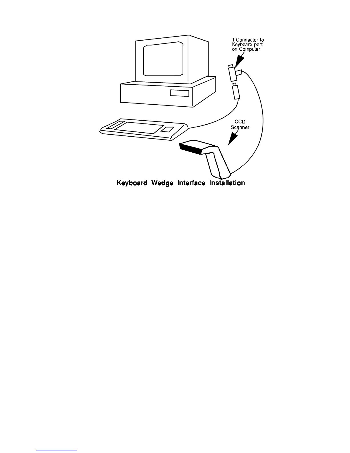
Step 2: Connect to your computer
Connect the keyboard to the female
end of the T-connector of the cable
provided. Plug the male end of the
T-connector into the keyboard port
of your computer.
Review the installation diagram on
the following page.
Step 1: Turn off your computer
If you have not already done so, turn
off your computer to avoid any
accidental damage to the scanner and
your computer.
Installing CCD Scanner
(Keyboard Wedge Interface)
6
Installing Keyboard Wedge Interface CCD Scanner
Step 3: Turn on your computer
Start up your computer. It should
boot up normally. If a keyboard
error appears, there may be an
incompatibility between the computer and the scanner keyboard type.
The scanner will activate with a
“beep” indicating a successful
installation.
You may now test your scanner by
scanning any bar code. The bar code
number will appear on the screen of
your computer.
Step 4: Turn to Chapter 4
You are now ready to program the
keyboard wedge interface CCD
scanner to meet the specific requirements of your application
environment.

7
• • • • • • •
3
This chapter describes the procedure
for installing the CCD scanner using
an RS232 interface.
Step 1: Turn off your computer
If you have not already done so, turn
off your computer to avoid any
accidental damage to the scanner and
computer.
Step 2: Decide on power access
There are 2 models of RS232 CCD
scanner. The first one without DCJACK on the cable is named
XXXXR9D of its model. Its connec-
tion requires +5V DC to be input
from the computer directly. Another
one with DC-JACK on the cable is
named XXXXR9R of its model. This
connection requires +8V~+14V DC
to be input from the external adaptor
to the DC JACK or the PIN-9 of
RS232 port of your computer(see
Appendix I page 45). If you are
using the power provided through
your terminal, please see Step 3, If
you are using an external connection,
go to Step 4.
Step 3: Connect to your terminal
Connect the 9-pin femal connector
(DB9F without DC jack) to the male
equivalent (DB9M) port in your
terminal.
Installing CCD Scanner
(RS232 interface)

8
Installing RS232 Interface CCD Scanner
Step 4: Connect to your computer
Step 5: Turn on your computer
Your computer should boot up
normally. The scanner should
activate with a beep indicating a
successful installation.
Connect the 9-pin female connector
(DB9F with DC jack) to the male
equivalent (DB9M) port on your
computer . Provide power to the DC
jack on the DB9F connector by
using an external adapter (see
Specifications in Appendix I).
Review the installation diagram on
the following page.

9
Installing RS232 Interface CCD Scanner
Step 6: Test your RS232 Interface CCD Scanner
Your scanner may now be tested
using software designed to read bar
code data from the RS232 port. The
following sample program written in
BASIC is sufficient for this purpose:
10 open COM1:“9600,N,8,1,cd,ds,cs” as #1
20 input #1, A$
30 print A$
40 go to 20
With this program running, the
number of any bar code you scan
will appear on your screen. Press
[CTRL + C] to exit from this
software program.
Step 7: Turn to Chapter 4
You are now ready to program the
RS232 Interface CCD scanner to
meet the specific requirements of
your application environment.

10

11
• • • • • • •
4
• Buzzer setting: 2KHz/120msec
• Inter-message delay: None
• Inter-character delay: None
• Header/trailer: None
• Keyboard type: IBM AT
• Keyboard language: U.S. English
• Message suffix: Enter
• Handshake protocol: None
• Message suffix: CR/LF
• Baud rate: 9600
• Data bit: 8
• Stop bit: 1
• Parity: None
• Standard character set
• No start/stop character transmission
• Check digit disabled
• Standard character set
• Start/stop characters (A,B,C,D)
transmitted.
Keyboard
Wedge
RS232
Code 39
Quick Install Programming
This chapter describes a fast procedure for programming the Series
CCD scanner. The Quick Install
option has been pre-set for a common combination of features.
Step 1: Decide on your requirements
Review the following list of pre-set
default values for the CCD scanner
General
Codabar

12
Quick Install Programming
• All UPC and EAN formats enabled
• Addendum disabled
• UPC-A leading characters transmitted
• UPC-A check digits transmitted
• UPC-E leading characters not
transmetted
• UPC-E check digits not transmitted
• EAN-8 and EAN-13 check digits
transmitted
• No forced conversion of UPC-E to
UPC-A
• FNC 2 concatenation disabled
• Check digit calculated but not
transmitted
• Fixed code length of 10 digits
• Start/Stop characters (2 bars)
transmitted
• Check digit disabled
• Fixed code length of 10 digits
• Check digit disabled
• Enabled
• Transmission disabled
• If enabled, pre-set bar code
identifiers are as follows:
UPC-E: E
UPC-A: E
EAN-13: F
EAN-8: FF
Standard 2 of 5: H
Interleaved 2 of 5: I
Codabar: N
Code 39: M
Code 128: K
Code 93: L
UPC and EAN
Code 128
Standard
2 of 5
Interleaved
2 of 5
Code 93
Bar Code
Identifier

13
Quick Install Programming
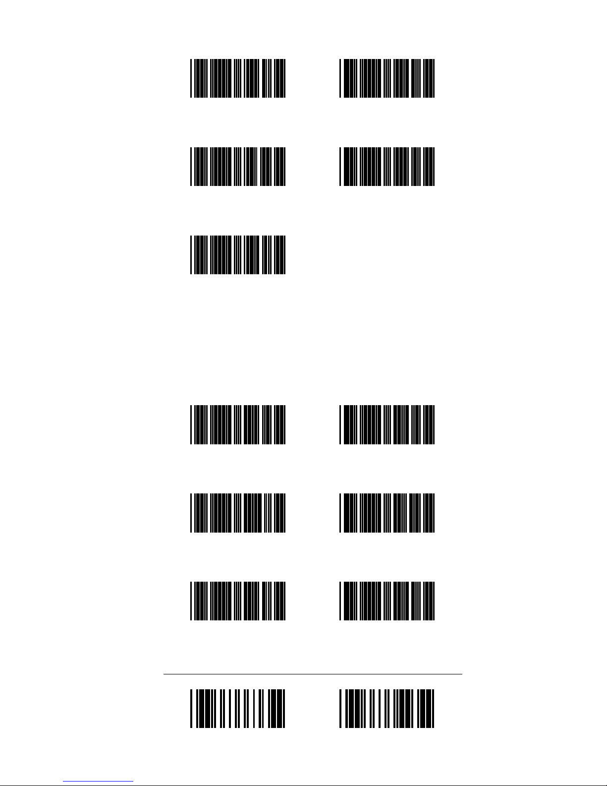
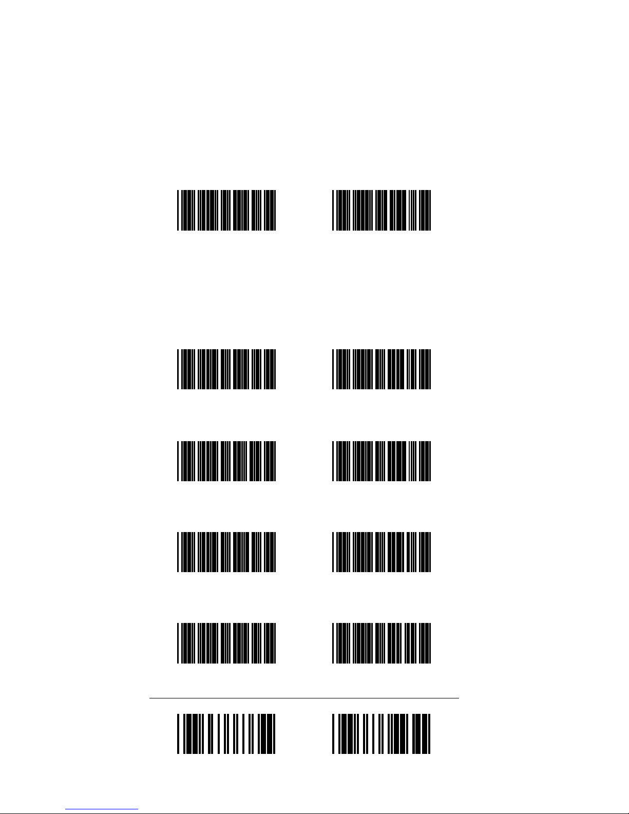
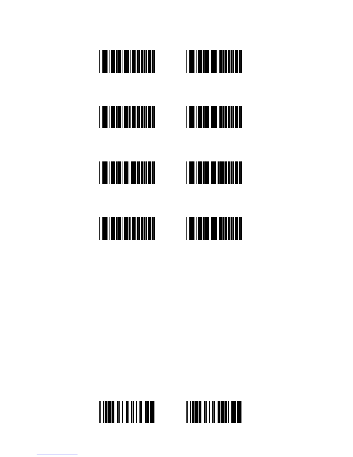
Step 2: Program your scanner
If all or most of your system requirements match the default settings
listed above, scan the three bar codes
on the following page in order.
The reading of this code installs the
default values for ALL parameters.
NOTE:
Program
(enter into programming mode)
If your requirements exactly match
all of the default settings, you have
finished the programming phase and
may now enjoy the use of your bar
code scanning equipment.
End
(save settings and end programming mode)
Reset
(program all features to default values)

14
Quick Install Programming
Step 3: Custom programming
If your system requirements do not
exactly match the default values, turn
to Chapter 5 and follow the procedure for custom programming the
special features which you require.
Likewise, if only a few parameters
need to be changed for a new
application, there is no need to totally
reconfigure all of the parameters.
Program only the special features you
require; those which are left alone
will keep their original value.

15
• • • • • • •
5
This chapter includes many features
which are available for custom
programming the Series CCD
scanner to match the specific requirements of your application
environment. You may individually
select and program the special
features that you desire in the following way:
• Locate the special feature
• Scan Program”
(at the bottom left of each page)
• Scan your specific choice
• Scan End”
(at the bottom right of each page)
The default value for each parameter
is indicated by asterisks and bold
typeface (e.g., * Default *).
Custom Programming
Page
• Buzzer setting ........................... 16
• Trigger switch mode ................. 17
• Inter-message delay .................. 18
• Inter-character delay ................. 18
• Header/trailer ............................ 19
• Keyboard language
and type selection ................20-21
• Message suffix .......................... 22
(continued on following page)
Quick reference directory
General
Parameters
Keyboard
Wedge
Parameters

16
1 KHz @ 200 mSec
General Parameters
Quick reference directory
• Handshaking protocol............... 23
• Baud rate ................................... 24
• Parity ......................................... 25
• Data bit...................................... 25
• Stop bit ...................................... 25
• Message suffix .......................... 26
• Code 39 ................................27-28
• Interleaved 2 of 5 .................29-30
• UPC and EAN......................31-34
• Codabar ................................35-36
• Code 128 ..............................37-38
• Code 93 ..................................... 38
• Bar Code Identifiers.............39-41
RS232
Parameters
Bar Code
Symbologies
Buzzer Setting
1 KHz @ 120 mSec
* 2 KHz @ 120 mSec * 2 KHz @ 200 mSec
Disable
Program End
There are five different buzzer
settings available. Changing the
setting will alter the audio indication
of a successful scan.

17
General Parameters
Trigger Switch Mode
The Trigger Switch Mode
provides four different
trigger setting available.
NORMAL MODE:
The scanner will turn off
after a successful reading,
you must press the trigger
switch again for next
reading.
AUTO SCAN MODE:
This is for hand free
operation, If you program
this mode, the scanner
light up always, but this
mode does not allow the
same bar code to be read
twice.
REPEAT MODE:
This mode is similar to the
Auto Scan Mode, but
allows to double reading
the same bar code.
ALTERNATE MODE:
When scanner is programmed in this mode, the
scanner willl light up when
pressing the scanner
trigger switch once, and
turn off for next pressing.
Program
End
*Normal Mode*
Auto Mode
Repeat Mode
Alternate Mode

18
Inter-Message delay
General Parameters
Program
End
Inter-message delay refers to the time
elapsed between when data is read
and when it is sent to the host
computer. Adjusting the intermessage and inter-character delay
may improve data transmission when
operating in conjunction with a fast
computer or incompatible DOS
version.
* None * 100 msec
500 msec
1 sec
Inter-Character delay
The inter-character delay may be
programmed to match various
computer response times.
10 msec
* None *
20 msec
250 msec
50 msec

19
General Parameters
Header and Trailer
Program
End
Header Trailer
Set
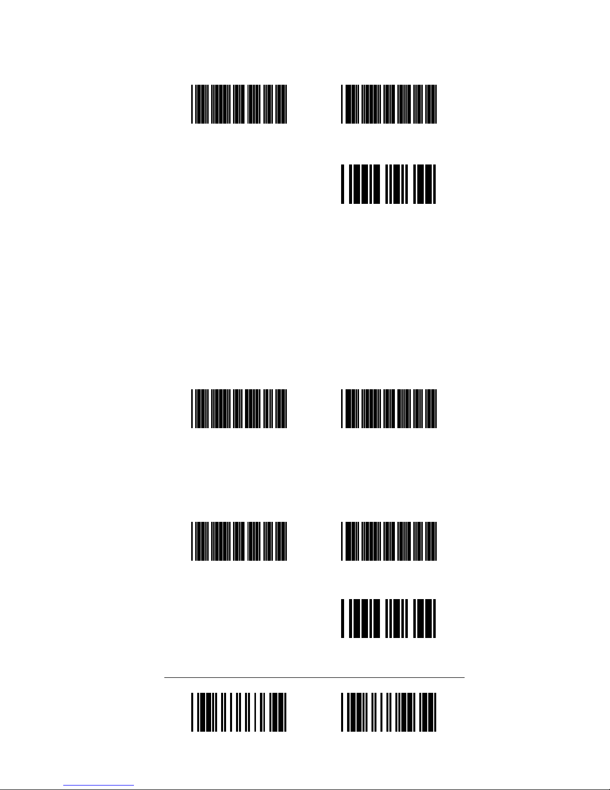
Any desired header or trailer may be
programmed into the CCD scanner.
The header/trailer will be automatically attached to the start/end of the
code transmitted. The maximum
length is ten digits.
The pre-set default value is for no
header nor trailer. If you wish to
program these parameters, you must
first enable reading of the Full
“ASCII” character set under the
Code 39 configuration.
The programming procedure is then
as follows:
• Scan “Program”
• Scan “Header” or “Trailer”
• Scan the desired characters in the ASCII
table (Ref:Appendix II)
• Scan “Set”
• Scan “End”

20
KEYBOARD WEDGE PARAMETERS
Keyboard Wedge Parameters
Program
End
In the keyboard wedge mode of
operation, the scanner must be
configured to match your keyboard
emulation and language. A message
suffix feature appends any message
from the scanner with the programmed character.
IBM 3472/3477
(For Asian Area Only)
IBM 3472/3477
IBM PS2/30
IBM 3196
NEC 286/386
IBM 5550
Keyboard Language and Type Selection

21
Program
End
Keyboard Wedge Parameters
* IBM AT U.S.English * IBM XT U.S.English
IBM AT German IBM XT German
IBM AT French IBM XT French
IBM AT Spanish IBM XT Spanish
IBM AT Itlian IBM XT Itlian
IBM AT Swedish IBM XT Swedish
IBM AT U.K.English IBM XT U.K.English

22
Message Suffix (keyboard wedge mode)
None Enter
Horizontal Tab Field Exit
Field Advance * Return *
Program
End
Keyboard Wedge Parameters

23
RS232 PARAMETERS
Program
End
When using the RS232 mode of
operation, the RS232 parameters
including handshaking, baud rate,
data bit, stop bit, parity and message
suffix must be configured to match
the requirements of your system.
500 mSec
200 mSec100 mSec
300 mSec
ACK/NAK handshaking response time
Handshaking Protocol
* None * RTS/CTS
XON/XOFF
ACK/NAK
RS232 Parameters
24
Program
End
600 1200
2400
4800
* 9600 *
19200
2 sec1 sec
3 Sec
5 Sec
Infinity
Baud Rate
RS232 Parameters

25
Parity
Program
End
Even
Odd
Space
* None *
Data Bit
7
* 8 *
Stop Bit
2
* 1 *
RS232 Parameters
26
Program
End
Message Suffix (RS232 mode)
None
CR
LF
* CR/LF *
ETX
EOT
Horizontal Tab
RS232 Parameters

27
BAR CODE SYMBOLOGIES
Each bar code symbology has its
own specifications. Your scanner is
able to read numerous symbologies.
A variety of programming features
allow you to configure the scanner
to your specific requirements.
Code 39 Symbology
Code 39 is the most popular bar
code symbology for ID, inventory,
and tracking purposes. The code is
alphanumeric and may vary in length
from 3 to 32 digits.
Program
End
* Enable Code 39 * Disable Code 39
The Full ASCII Code 39 permits the
transmission of the 128 characters
contained within the ASCII Table
(see Appendix II)
* Standard *
Character Set
Full ASCII
Character Set
Code 39 Character Set
Bar Code Symbologies

28
Program
End
Code 39 Check Digit
The check digit function provides
additional security. The calculation
and transmission of the check digit
are optional.
* Disabled * Calculated and
Transmitted
Code 39 Start/Stop Character
Calculated but
not Transmitted
This feature enables the transmission
of start and stop characters with the
bar code data message.
* Disable *
Enable
Bar Code Symbologies

29
Program
End
Interleaved 2 of 5 Symbology
Interleaved 2 of 5 is a numeric bar
code which has been widely used in
the shipping and warehouse
industries. The code can be very
compact in that both bars and spaces
encode information.
* Enable *
Interleaved 2 of 5
Disable
Interleaved 2 of 5
The check digit function is recommended when using a variable code
length. The calculation and transmission of the check digit are optional.
* Disable * Calculated and
Transmitted
Calculated but not
Transmitted
Interleaved 2 of 5 Check Digit
Bar Code Symbologies
30
Program
End
Interleaved 2 of 5 code length
Bar Code Symbologies
While Interleaved 2 of 5 is easily
decoded, it is also subject to errors if
parameters such as length are not well
adjusted. The default code length is
fixed at 10 digits. The variable setting
allows the code length to vary from 3
to 32 digits (even number only) :
• Scan “Program”
• Scan “Variable”
• Scan “End”
And if chosen, the use of the check
digit is recommended.
The option of changing from the preset length of 10 is also available. To
do this, you must first enable reading
of the “Full ASCII” character set
under the Code 39 configuration. The
programming procedure is then as
follows:
• Scan “Program”
• Scan “Fixed”
• Scan the desired length from the ASCII
Table
• Scan “Set”
• Scan “End”
The ASCII Code Table is found in
Appendix II.
Set
Fixed
Variable
31
UPC and EAN Symbologies
UPC and EAN bar code symbologies
are used mainly in retail applications.
Both are fixed length numeric bar
codes which use a check digit.
* Enable *
UPC and EAN
Disable
UPC and EAN
UPC and EAN Formats
* All *
EAN-8 or EAN-13
UPC-A and UPC-E
UPC-A and EAN-13
UPC-E
UPC-A
EAN-8 EAN-13
Program
End
Bar Code Symbologies

32
EAN Addendum
Program
End
* Disable * 5 Characters
2 Characters
2 or 5 Characters
UPC/EAN Transformations
UPC-A to EAN-13
* Not Allowed *
UPC-E to UPC-A
* Not Allowed *
UPC-A to EAN-13
Allowed
UPC-E to UPC-A
Allowed
Bar Code Symbologies
33
UPC and EAN Check Digits
Program
End
EAN-13 Check Digit
* Transmitted *
EAN-13 Check Digit
Not Transmitted
EAN-8 Check Digit
* Transmitted *
EAN-8 Check Digit
Not Transmitted
UPC-A Check Digit
* Transmitted *
UPC-A Check Digit
Not Transmitted
UPC-E Check Digit
* Transmitted *
UPC-E Check Digit
Not Transmitted
Bar Code Symbologies

34
Program
End
UPC Leading Characters
UPC-A Leading
Character
Not Transmitted
UPC-A Leading
Character
* Transmitted *
The leading characters can be used to
recognize the type of UPC code
received by the host computer.
Bar Code Symbologies
UPC-E Leading
Character
* Transmitted *
UPC-E Leading
Character
Not Transmitted

35
Program
End
Codabar Symbology
Bar Code Symbologies
Codabar is an numeric bar code used
in libraries and medical settings. It
varies in length from 3 to 32 digits.
Disable
Codabar
* Enable *
Codabar
Codabar Start/Stop Character Transmission
DC1-DC4 a/t, b/n, c/*, d/e
Transmission Disabled
* A, B, C, D *

36
Codabar Length
MAX. LEN
MIN. LEN
Set
Program
End
Bar Code Symbologies

37
Code 128 Symbology
Code 128 has the capability of
encoding all characters of the ASCII
table with a high density of characters
per inch. Owing to the high density, it
is important the bar code printing be
of high quality. Code 128 varies in
length from 3 to 32 digits.
* Enable *
Code 128
Disable
Code 128
* Disable * Enable
Code 128 FNC 2 Concatenation
* Disable *
Calculated and Transmitted
Program
End
Calculated but
not Transmitted
Code 128 Check Digit
Bar Code Symbologies
38
Program
End
MAX. LEN
Code 128 Lengh
MIN. LEN
Set
Code 93 Symbology
Code 93 is a compact alphanumeric
symbology often used on small
electronic components. Its code
length may vary from 3 to 32 digits.
Enable
Code 93
* Disable *
Code 93
Code 93 Length
MIN. LEN
MAX. LEN
Set
Bar Code Symbologies

39
Program
End
Bar Code Identifier
The Bar Code Identifier allows each
bar code symbology to have an
identifier code. This identifier code
is added to the beginning of any data
transmitted by the Series CCD
scanner.
The default value under the “Quick
Install” option disables bar code
identification. However a series of
letters has been pre-assigned to the
bar code symbologies (itemized in
Chapter 4) in case you choose to use
this feature. Simply scan “Program”,
then scan “Enable” and then scan
“End”.
Enable
Code Identifiers
* Disable *
Code Identifiers
Bar Code Symbologies

40
Program
End
Custom Bar Code Identifier
The option of changing from the preset letter assignment is also available.
To do this, you must first enable
reading of the “Full ASCII” character
set under the Code 39 configuration.
The programming procedure is then
as follows:
• Scan “Program”
• Scan “Enable”
• Scan the bar code symbology you wish
identify
• Scan the desired characters in the
ASCII Table (maximum 2 digits)
• Scan “Set”
• Scan “End”
The symbology codes are listed on
the following page. The ASCII Code
Table is found in Appendix II.
Bar Code Symbologies

41
UPC-A
EAN-13
EAN-8
Code 93 Code 39
Codabar
Code 128
Standard 2 of 5
Interleaved 2 of 5
Custom Bar Code Identifier
Program
End
Enable
Code Identifiers
UPC-E
Set
Bar Code Symbologies

42

43
• • • • • • •
6
Troubleshooting
• The type setting of computer is not
supported by the scanner.
• Cable defected.
• Wrong setting with the “Keyboard
Type Emulation” or “Keyboard
Language”. Please refer to the
keyboard wedge parameters setting
procedure on page 20-21.
• Unproper installation. Please turn
off the power of computer, connect
the scanner, then power on the
computer again.
• Buzzer defected.
• Scanner defected.
• The beep tone was disabled.
Please refer to page 16 for buzzer
setting.
• The bar code type is not supported
by the scanner. Please enable it
again.
• The bar code type has been
disabled or with unproper bar code
length setting. Please refer to 2640 for different bar code symbologies setting procedure.
• Wrong setting with the “Keyboard
Type Emulation” or “Keyboard
Language”. Please refer to the
keyboard wedge parameters setting
procedure on page 20-21.
• Protocol setting error.
• Bad bar code label.
• If you are using the keyboard
wedge scanner, maybe this scanner
is not compatible with the timing
of the keyboard interface in your
computer. Please adjust the setting
of “Inter-Character Delay” and/or
“Inter-Message Delay” on page 18.
When the scanner
is connected and
the computer is
turned on, a
“Keyboard error”
message appears.
When the scanner
is connected and
the computer is
turned on, the CCD
scanner does not
beep.
The CCD scanner
does not read the
bar code data.
The bar code data
transmitted to the
computer is
incorrect.
Situation Solution

44
Troubleshooting

45
• • • • • • •
A
Appendix I
Specifications
Light Source: Red LED (660nm)
Photo Sensor: CCD
Scanning Speed: 50 scans /second
Reading distance: 0-25mm
Resolution: 0.125mm
Readable label size: 60mm or 80mm
• Audible “beep” indicating successful reading of bar code data
• The keyboard wedge interface CCD
scanner: keyboard wedge interface
for IBM PC AT/XT, IBM PS/2,
NEC 286/386, IBM 5550, IBM
347x, IBM 3196
• The RS232 interface CCD scanner:
RS232C interface with 9-pin female
connectors
Automatically recognizes:
• UPC, EAN and JAN
• UPC and EAN Addendum
• Code 39 and Full ASCII Code 39
• Standard 2 of 5
• Interleaved 2 of 5
• Codabar
• Code 128
• Code 93
• “Quick Install” option for fast
programming of common parameter group
• Buzzer setting
• Keyboard type and language
• Bar code symbology setting
• Scanning speed
• Message suffix
• Header and trailer
OPTICAL
Status
Indicator
System
Interface
Decoding
Capability
Parameters
Programmable
Through
Scanning

46
• Inter-message delay
• Inter-character delay
• Serial interface handshaking
protocol
• Bar code identifier
• The keyboard wedge interface CCD
scanner: +5V DC
• The RS232 interface CCD sacnner:
internal +5V DC, or external
adapter from 110V/220V, 50/60Hz
AC to +9V ~ +14V DC with
polarity as follows:
• Weight: CCD scanner: 155g
(cable and connector not included)
• Operating temperature: 0
O
C to 50OC
• Storage temperature: -20
O
C to 60OC
• Humidity: 20% to 95% (non-
condensing)
• Ambient Ligh Rejection:
1500 Lux Max. (Flourescence)
800 Lux Max. (Sunlight)
Specifications
(programmable
parameters
continued)
MODEL:
20
XX
R9D
Connector Pin
Assignments
for connect
to terminal
MODEL:
20
XX
R9R
Connector Pin
Assignments
for connect
to terminal
Power
Requirement
Physical
Environmental
9-pin DB Female (DB9F)
Connect
For RS232C
Interface
#2: RX
#3: TX
#5: Ground
#7: RTS
#8: CTS
#9: +5V DC Power
9-pin DB Female (DB9F)
Connect
For RS232C
Interface
#2: TX
#3: RX
#5: Ground
#7: CTS
#8: RTS

47
25-pin DB Female Connect
For RS232C Interface
#2: RX
#3: TX
#4: CTS
#5: RTS
#7: GND
MODEL:
20
XX
R2R
Connector Pin
Assignments
for connect
to terminal

48

49
• • • • • • •
A
Appendix II
ASCII Code Table
NUL
SOH
STX
ETX
EOT
ENQ
ACK
BEL
BS
HT
LF
VT
FF
CR
SO
SI
DLE
DC1

50
ASCII Code Table
DC2 ESC
DC3
FS
GSDC4
EM
CAN
ETB
US
SYN
RS
NAK
SUB
!
“
#
SP

51
ASCII Code Table
2
)
1
(
0
‘
/&
-
%
.
$
5,
+
4
*3

52
6
?
G
>
F
=
E<
D
;
C
:
B9
A
8
@
7
ASCII Code Table

53
P
Y
XO
W
N
V
M
U
L
TK
S
J
RI
Q
H
ASCII Code Table

54
ASCII Code Table
b
k
a
j
i
`
h
_
g
^
f
]
e
\
d
[
cZ

55
ASCII Code Table
}t
|s
{
r
z
q
yp
xo
w
n
v
m
u
l

56
~
DEL
ASCII Code Table

ISSUED: NOV. 97' - V 7
 Loading...