

Janome JR3200 series, JR3300 series, JR3400 series, JR3500 series, JR3600 series Operation Manual

JANOME DESKTOP ROBOT
JR3000 Series
Thank you for purchasing this Janome Robot.
Before using your robot, please read this manual thoroughly
and always make sure you use the robot correctly. In
particular, be sure to thoroughly read “For Your Safety” as it
contains important safety information.
After reading this manual, store in a safe place that can be
easily accessed at any time by the operator.
This manual is written according to IEC 62079.
Original Instructions
Operation Manual
Setup
(For Installation Operators)
Installation operators are persons who have undergone installation training at
Janome or at a representative branch. People responsible for installation work should
complete this training.

Setup
Desktop Robot JR3000
PREFACE
The Janome Desktop Robot JR3000 Series are new, low-cost, high-performance robots. With these
robots we succeeded in reducing the price while maintaining functionality. The combined use of
stepping motors and specialized micro step driving circuits saves both energy and installation space.
This manual covers the JR3200, JR3300, JR3400, JR3500* and JR3600* series (*under
development). There are several manuals pertaining to these robots.
JR3000 Series
For Your Safety
This is important safety information. Make sure you read this before using the
robot.
Setup
Explains how to set up the robot.
■ Make sure you read this manual ■
NOTE: This manual is designed for people who have received safety and
installation training regarding the robot.
Maintenance
Explains maintenance procedures for the robot.
■ Make sure you read this manual ■
NOTE: This manual is designed for people who have received safety and
maintenance training regarding the robot.
Basic Instructions
Provides part names, data configurations, and the basic knowledge
necessary to operate the robot.
Quick Start
Explains the actual operation of the robot by creating and running simple
programs.
Teaching Pendant
Operation
Explains how to operate the robot via the teaching pendant.
Functions I
Explains point teaching.
Functions II
Explains commands, variables, and functions.
Functions III
Explains functions such as All Program Common Settings and PLC programs.
Functions IV
Explains Customizing Functions.
External Control
(I/O / Fieldbus)
Explains I/O and Fieldbus.
Please refer to this manual if you are using Fieldbus.
Communication
Control (COM/LAN)
Explains COM 1 – 3 and LAN communication control.
Camera & Sensor
Functions
Explains the functions of the attachable camera and Z position sensor.
Specifications
Outlines general specifications such as the robot’s operating range, mass etc.
Auxiliary Axis
Functions
Explains the auxiliary axis functions.
PC Operation
Explains how to use the PC software JR C-Points II.
Application
Specifications
Explains the specialized functions of the various application specifications.
Note: The content of this manual may differ from the robot in your possession due to updates to the
product specifications.
The descriptions within this manual are based on standard specifications. The menu item names etc.
may vary depending on the model type.
1
Setup
Desktop Robot JR3000
To make full use of the machine’s functions and capabilities, make sure that
you use the robot according to the correct handling/operation procedures
that are written in the manuals listed on the previous page.
If you turn OFF the power after making changes to robot’s settings or data
without saving, these changes are lost and the robot will revert to its original
settings. Make sure that you save any changes to data and/or settings.
Before using this robot for the first time, make sure you back up robot data
and save the individual configuration information. Individual configuration
information is needed when replacing internal circuit boards.
Always make sure the machine is grounded through the power
cord. Do not use the machine when it is not grounded.
Improper grounding causes electric shocks, fires, malfunction, and
unit breakdown.
Warning
Warning
Make sure that the machine power supply is OFF before
connecting the power cord.
Failure to do so could cause electric shock and/or injury.
Do not handle or operate the robot in ways not covered in the
manuals listed on the previous page. Contact Janome (listed on the
back page of this manual) for repairs.
Failure to do so can cause electric shock and/or injury.
Warning
Note: The operation methods described in this manual are indicated as follows:
Operation via the teaching pendant
Operation via PC (JR C-Points II)
TP
PC
Attention
Attention
Attention
2

Setup
Desktop Robot JR3000
CONTENTS
PREFACE ............................................................................................................................................... 1
CONTENTS............................................................................................................................................. 3
FOR YOUR SAFETY .............................................................................................................................. 5
1. SYSTEM CONFIGURATION ............................................................................................................ 13
2. INSTALLATION ................................................................................................................................. 14
2.1 Common to the JR3200 Series ................................................................................................... 15
2.2 Common to the JR3300 Series ................................................................................................... 16
2.3 Common to the JR3400 Series ................................................................................................... 17
2.4 Teaching Pendant Hanging Ring ................................................................................................ 18
2.5 Cable Connection ........................................................................................................................ 19
2.5.1 JR3200 Series....................................................................................................................... 19
2.5.2 JR3300 Series....................................................................................................................... 21
2.5.3 JR3400 Series....................................................................................................................... 23
2.5.4 Protective Grounding ............................................................................................................ 26
2.5.5 Attaching Devices ................................................................................................................. 27
2.6 Connecting to a PC (Ethernet) .................................................................................................... 28
2.6.1 JR C-Points II Limited Edition Requirements........................................................................ 29
2.6.2 LAN Cable ............................................................................................................................. 30
2.6.3 LAN Port ................................................................................................................................ 31
2.6.4 Communication Settings (IP Address Settings) .................................................................... 31
2.6.5 Robot IP Address Settings .................................................................................................... 32
2.6.6 PC IP Address Settings ........................................................................................................ 32
3. BACKING UP AND RESTORING ROBOT DATA ........................................................................... 33
3.1 Backup Data ................................................................................................................................ 33
3.2 Restore Data ................................................................................................................................ 34
3.3 Backing Up and Restoring Data Via USB Memory ..................................................................... 34
4. SENDING AND RECEIVING C&T DATA ......................................................................................... 35
5. TRANSMITTING ROBOT SYSTEM SOFTWARE ........................................................................... 37
6. CLOCK SETTINGS ........................................................................................................................... 39
7. SETTINGS NEEDED FOR TEACHING ........................................................................................... 40
7.1 3 Axis Specifications: Tool Data .................................................................................................. 40
7.2 4 Axis Specifications: Tool Data .................................................................................................. 41
7.3 Workpiece Mass .......................................................................................................................... 43
8. SETTINGS NEEDED TO MAKE A RUN .......................................................................................... 44
8.1 External Run Mode Settings ........................................................................................................ 44
8.2 Setting Program Numbers ........................................................................................................... 45
3

Setup
Desktop Robot JR3000
8.2.1 Changing Program Numbers ................................................................................................ 45
8.2.2 Program Number Reading Format ....................................................................................... 45
8.2.3 Program Number Switching Method ..................................................................................... 46
8.3 I/O-S Settings (Optional) .............................................................................................................. 47
9. CONVERTING JR2000/JR2000N DATA TO JR3000 DATA ........................................................... 48
4
Setup
Desktop Robot JR3000
FOR YOUR SAFETY
The safety notes outlined below are provided in order to ensure safe and correct usage of the product
in addition to preventing injury to the operator, other people and damage to property as well.
・・・・・ Be sure to follow the safety guidelines detailed here ・・・・・
Symbols are also listed alongside the safety note explanations. Please refer to the list below for an
explanation of these symbols.
Symbols that indicate the level of danger and/or damage.
The level of danger or damage that could occur as a result of ignoring these safety guidelines and
misusing the robot are classified by the following symbols.
This symbol indicates an imminent risk of se
rious injury or
death.
This symbol indicates a risk of serious injury or death.
This symbol indicates the possibility of serious injury or damage
to property.
The following symbols list the nature of the danger and any necessary safety methods to be taken.
Indicates caution must be taken
Take Caution (General Precaution)
Indicates a forbidden action
Never do this (General Precaution)
Do not disassemble, modify or repair.
Do not touch (Contact Prohibition)
Indicates a required action
Be sure to follow instructions (General Requirement)
Be sure to unplug the power supply cord
Make sure the machine is grounded
Warning
Danger
Caution
5
Setup
Desktop Robot JR3000
FOR YOUR SAFETY
If using auxiliary axis functions to operate a motor, such as a servo motor, that
produces feedback and/or a motor with high output etc., or when using auxiliary axes
in the formation of a robot etc., we ask that you perform a risk assessment on your side
and take any necessary safety measures.
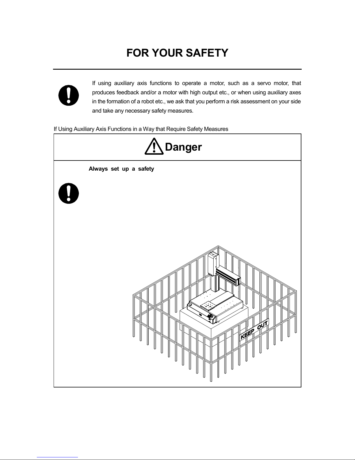
If Using Auxiliary Axis Functions in a Way that Require Safety Measures
Always set up a safety
enclosure or cover the robot with a guard so the
moveable parts cannot be touched.
Anyone within the maximum reach of the robot and the auxiliary axes it is controlling
may be injured. Using the I/O-S connector accessory, set up an
emergency stop
interlock system that cuts off the motor power to the auxiliary axes and is
triggered when the entrance to the safety enclosure is opened. Make sure there is
no other way of entering the restricted area.
Furthermore, put up a “No Entry” or “Do Not Operate
” warning sign in a clearly
visible place.
Example:
Danger
6

Setup
Desktop Robot JR3000
FOR YOUR SAFETY
If Using Auxiliary Axis Functions in a Way that Require Safety Measures
When power to the robot is ON, never enter the safety enclosure or put your
face, hands, or any part of your body inside.
Failure to do can result in injury.
When entering the safety enclosure due to something wrong with the robot or a
peripheral device, or to inspect or lubricate the machine etc.,
with both the power
supply breaker and the robot switched OFF, make sure to lockout and tagout
and confirm there is no electricity flowing to the robot.
Failure to do so can cause electric shock or injury.
When creating a robot system using auxiliary axis functions, if the system can be
categorized as an industrial robot, operators in Japan who engage in teaching,
inspections, adjustments and/or repairs must take lectures as part of the “special
education” for industrial robots as stipulated by Article 59 of the Japan
Industrial Safety and Health Act and the related regulations.
Likewise, when using the robot outside of Japan, make sure to do so according to the
laws and guidelines of the country where it is used.
Before performing a run or operation, always check the following:
• Obstacles: Make sure there are no obstacles or people within the
safety enclosure.
• Installation:
Make sure the robot is installed properly, that there are
no abnormalities with the robot and the surrounding
devices, and that the teaching pendant and tools are in
the appropriate places.
• Emergency Stop Switch: Make sure the I/O-S circuit (interlock) and emergency
stop switch(s) are functioning properly.
It is potentially dangerous to operate the robot without making these checks first.
Warning
Danger
7
Setup
Desktop Robot JR3000
FOR YOUR SAFETY
If Using Auxiliary Axis Functions in a Way that Require Safety Measures
Construct a safety enclosure that is strong enough to
protect the operator
against such dangers as the tool or workpiece splintering, etc.
When working within the safety enclosure, use protective ge
ar such as a helmet,
protective gloves, protective goggles, and safety shoes.
Failure to follow these safety measures can result in injury.
If objects that the robot grasps have a risk of falling or being projected,
take into
account the size, weight, and chemical composition of the objects
for the
required safety precautions.
Failure to do so can result in injury or unit breakdown.
When working within the safety
enclosure, make sure not to come within the
maximum range of the robot.
Failure to do so can cause injury.
When starting a run, first confirm there are no people inside of the safety enclosure
and there are no obstacles that could interfere with the run.
Failure to do so can cause injury or unit breakdown.
Warning
8
Setup
Desktop Robot JR3000
FOR YOUR SAFETY
Do not use where flammable or corrosive gas is present.
Leaked gas accumulating around the unit causes explosions and fire.
Make sure that you securely install the unit in a place that can fully withstand
both the unit’s weight and its usage. Install the robot and switchbox on a workbench
60cm or higher above floor level, and install the robot in the center of the workbench.
In addition,
for units with a cooling fan on the back, allow for 30cm or more
clearance between the back of the unit and the wall.
If installation is inadequate, the unit can drop or
fall over causing injury and unit
breakdown. Also, inadequate installation causes overheating and fire.
Make sure to power the unit within its rated current range.
Failure to do so causes electric shocks, fires, and unit malfunction.
Plug the power cord into the wall outlet firmly.
Failure to do so causes the plug to heat up resulting in fire.
Be sure to use the unit within its indicated voltage range.
Failure to do so causes fires and unit malfunction.
When replacing fuses, or
inspecting or lubricating the unit, unplug the power
cord from the wall outlet, then remove the cord from the main unit and make
sure there is no electrical current. Also, do not touch any of the power inlet pins
within 5 seconds of removing the power cord. Failure to follow these steps causes
electric shocks and injury.
Warning
Danger
9
Setup
Desktop Robot JR3000
FOR YOUR SAFETY
Always make sure the machine is grounded through the power cord.
Do not use the machine when it is not grounded.
Improper grounding causes electric shocks, fires, malfunction, and unit breakdown.
Wipe the power plug with a clean, dry cloth periodically to eliminate dust.
Dust accumulation deteriorates the electrical insulation and causes fires.
Be sure to unplug the power cord from the power outlet when the unit is not in
use for long periods of time.
Dust accumulation causes fires.
Be sure to turn OFF the unit before inserting or removing cords and cables such
as the teaching pendant cable.
Failure to do so causes electric shock, fire, data loss, and unit malfunction
Do not attempt to disassemble or modify the unit.
Disassembly or modification causes electric shocks and unit malfunction.
Do not allow water or oil to come in contact with the unit, control box
or the
power cord.
Contact with water or oil causes electric shock, fire, or unit malfunction.
IP Protection Rating: IP20.
If anything unusual occurs, such as a burning smell or unusual sound, stop
operation and unplug the power cord immediately. Contact the dealer from
whom you purchased the robot or the office listed on the last page of this
manual.
Continuing to use the robot without addressing the problem causes electric shock, fire,
or unit breakdown.
Warning
10
Setup
Desktop Robot JR3000
FOR YOUR SAFETY
Do not drop or jar the unit during transport and/or installation.
This causes injuries or damages the unit.
Before performing any operation, ensure there is no imminent danger to any of
the operators. Failure to do so causes injury.
Use the unit in an environment between 0 and 40°C, with a humidity level of 20 –
90%, and without condensation.
Use outside of these conditions can cause unit malfunction.
Use the unit in an environment where no electrical noise is present.
Failure to do so causes unit malfunction or breakdown.
For models with I/O-S circuits, when installing the unit, take safety measures
such as setting up area sensors and an enclosure.
If there are no safety
measures in place and someone enters the area of operation
when the robot is running, they may be injured.
Keep the emergency stop switch within reach of the operator when running or
operating the robot.
If the robot is operated when the emergency switch is not within reach, it may not be
possible to stop the robot immediately and safely. This is potentially dangerous.
Make sure that you regularly perform a function check of the emergency stop
switch(s). Also, for models with I/O-S circuits, regularly perform an I/O-S circuit
function check.
If the robot is operated without making these checks, it may not be possible to stop the
robot immediately and safely in an emergency. This is potentially dangerous.
Caution
11
Setup
Desktop Robot JR3000
FOR YOUR SAFETY
When attaching tools etc., make sure they are securely fitted before running the
robot.
Failure to do so causes injury or breakdown.
When using the machine for extended periods of time, check and make sure
none of the main unit’s mounting screws are
loose, and perform a routine
inspection every 3 months. Failure to do so causes injury or breakdown.
Be sure to check the connections of the cords and cables to the main unit.
Improper wiring causes unit malfunction or breakdown.
Secure the movable parts of the unit before transportation.
Failure to do so causes injury or breakdown.
When lifting and transporting the robot, do so with 2 or more people.
Failure to do so causes injury or breakdown.
Use the unit in an environment that is not exposed to direct sunlight.
Direct sunlight causes unit malfunction or breakdown.
Individual Configuration Information varies for each individual unit even if they are the
same model.
Do not use backup data with a different robot. The robot cannot
function normally with backup data from a different robot.
Caution
12
Setup
Desktop Robot JR3000
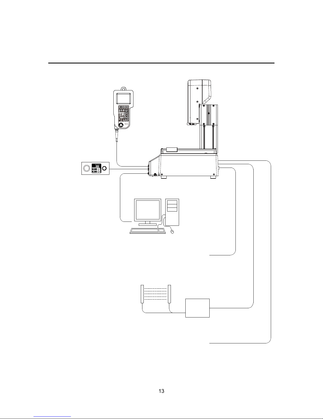
1. SYSTEM CONFIGURATION
PC*1 with a
Windows® 7 / 8 / 8.1
operating system
Tool*
1
Dispenser, Electric Screwdriver, etc.
PLC, etc.
Switchbox
(Switchbox specification
robots only)
RS-232C
Cable*1 *2
Area Sensor, etc. *
1
Teaching
Pendant
(Optional)
Robot
Example: JR3203N-BC
Windows is a registered trademark of Microsoft
*
1
Not included
*
2
An RS-232C port on the back of the robot is optional
13
Setup
Desktop Robot JR3000
2. INSTALLATION
Do not use where flammable or corrosive gas is present.
Leaked gas accumulating around the unit causes explosions and fire.
Make sure that you securely install the unit in a place that can fully withstand
both the unit’s weight and its usage. Install the robot and switchbox on a workbench
60cm or higher above floor level, and install the robot in the center of the workbench. In
addition, for units with a cooling fan on the back, allow for 30
cm or more
clearance between the back of the unit and the wall.
If installation is inadequate, the unit can drop or
fall over causing injury and unit
breakdown. Also, inadequate installation causes overheating and fire.
Do not drop or jar the unit during transport and/or installation.
This causes injuries or damages the unit.
Use the unit in an environment between 0 and 40°C, with a humidity level of 20 –
90%, and without condensation.
Use outside of these conditions can cause unit malfunction.
Use the unit in an environment where no electrical noise is present.
Failure to do so causes unit malfunction or breakdown.
Use the unit in an environment that is not exposed to direct sunlight.
Direct sunlight causes unit malfunction or breakdown.
Caution
Danger
Warning
14
Setup
Desktop Robot JR3000
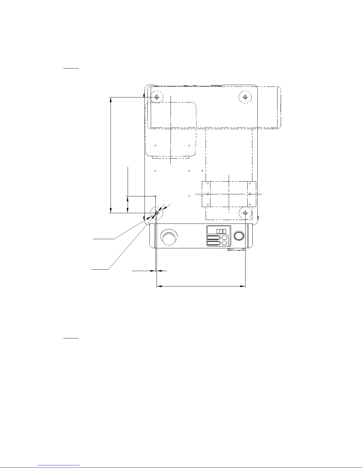
2.1 Common to the JR3200 Series
NOTE
When installing, rotate the rubber feet to adjust the height. Be sure to make them stable.
There are four rubber feet (ϕ30).
The values within the brackets above are for reference only.
NOTE
• The robot may rattle depending on the tool mass. If so, be sure to secure the unit. To s e cu r e t he
unit, remove the rubber feet and use the 4 M8 screw holes used for fastening the rubber feet.
• Have at least 2 people carry the unit when transporting it.
• The unit’s mass is 20kg for 3 axis specifications and 22kg for 4 axis specifications.
(40.1)
275
(3)
210
4-M8
4-φ30
(Rubber Feet)
Example: JR3203N-AC
15
 Loading...