

Janome JP-1004, JP-3004, JP-5004, JPH-104, JPH-204 Operation Manual
...
JANOME ELECTRO PRESS
JP-104 JP-204 JP-504 JP-1004
JP-1504 JP-3004 JP-5004
JPH-104 JPH-204 JPH-504 JPH-1004
JPH-1504 JPH-3004 JPH-5004
JPU-104 JPU-204 JPU-504 JPU-1004
JPU-1504 JPU-3004 JPU-5004 JPU-8004
Operation Manual
<Setup>
“For Qualified Installer ONLY”
Thank you for purchasing the Electro Press.
*Read this manual thoroughly in order to properly use this machine.
Be sure to read “For Your Safety” before you use the machine. It
will protect you from possible dangers during operation.
*After having read this manual, keep it in a handy place so that you
or the operator can refer to it whenever necessary.
FOR YOUR SAFETY
Safety Precautions
The precautions stated in this manual are provided for the customer to make the best use of this
product safely, and to provide preventive measures against injury to the customer or damage to
property.
・・・・・Be sure to follow the instructions・・・・・
Various symbols are used in this manual. Please read the following explanations to understand what
each symbol stands for.
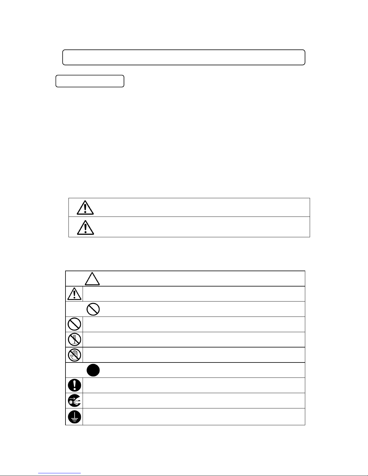
● Symbols indicating the Degree of Damage or Danger
The following symbols indicate the degree of damage or danger which may be incurred if you
neglect the safety notes.
● Symbols indicating the type of Danger and Preventive Measures
The following symbols indicate the type of safety measure that should be taken.
Warnings
Cautions
These “Cautions” indicate the possibility of accidental injury or
damage to property.
These “Warnings” indicate the possibility of death or serious injury.
Indicates prohibition.
Do not touch.
(
contact prohibition)
Never do this. (general prohibition)
Be sure to unplug the power supply from wall outlet.
Do not disassemble, modify or repair.
Be sure to follow instructions.
Be sure to check grounding.
Indicates necessity
Indicates the type of safety measure that should be taken.
Take care.
(
General caution)
Setup Electro Press JP Series 4 i
FOR YOUR SAFETY
A person entering the machine’s operation area may be injured.
Put up a “No Entry” or “No Operating” warning sign in a clearly visible
position near the machine.
Do not sprinkle water or oil on the unit, control box, or its cable.
Contact with water can cause electric shock, fire, or malfunction of the unit.
IP Protection Rating is IP40.
Power the unit only with the rated voltage.
Excessive voltage can cause fire or malfunction of the unit.
Check the mounting screws regularly so that they are always firmly
tightened.
Loose screws may cause injury or damage.
Regularly replace the built-in battery (optional) in the body or control
box. It is preferable to replace it every 3 years.
Failure to do so may cause malfunction or defect.
Keep the emergency stop switch within reach of an operator while
teaching and running the machine.
Failure to do so is dangerous because the machine cannot be stopped
quickly and safely.
Regularly check that the I/O-S circuits and emergency stop switch work
properly.
Failure to do so is dangerous because the machine cannot be stopped
quickly and safely.
Do not leave the unit plugged in (power cord and connectors) when it
is not in use for long periods of time. Dust can cause fire.
Be sure to shut off the power supply before removing the power cord.
Warnings
Setup Electro Press JP Series 4 ii
FOR YOUR SAFETY
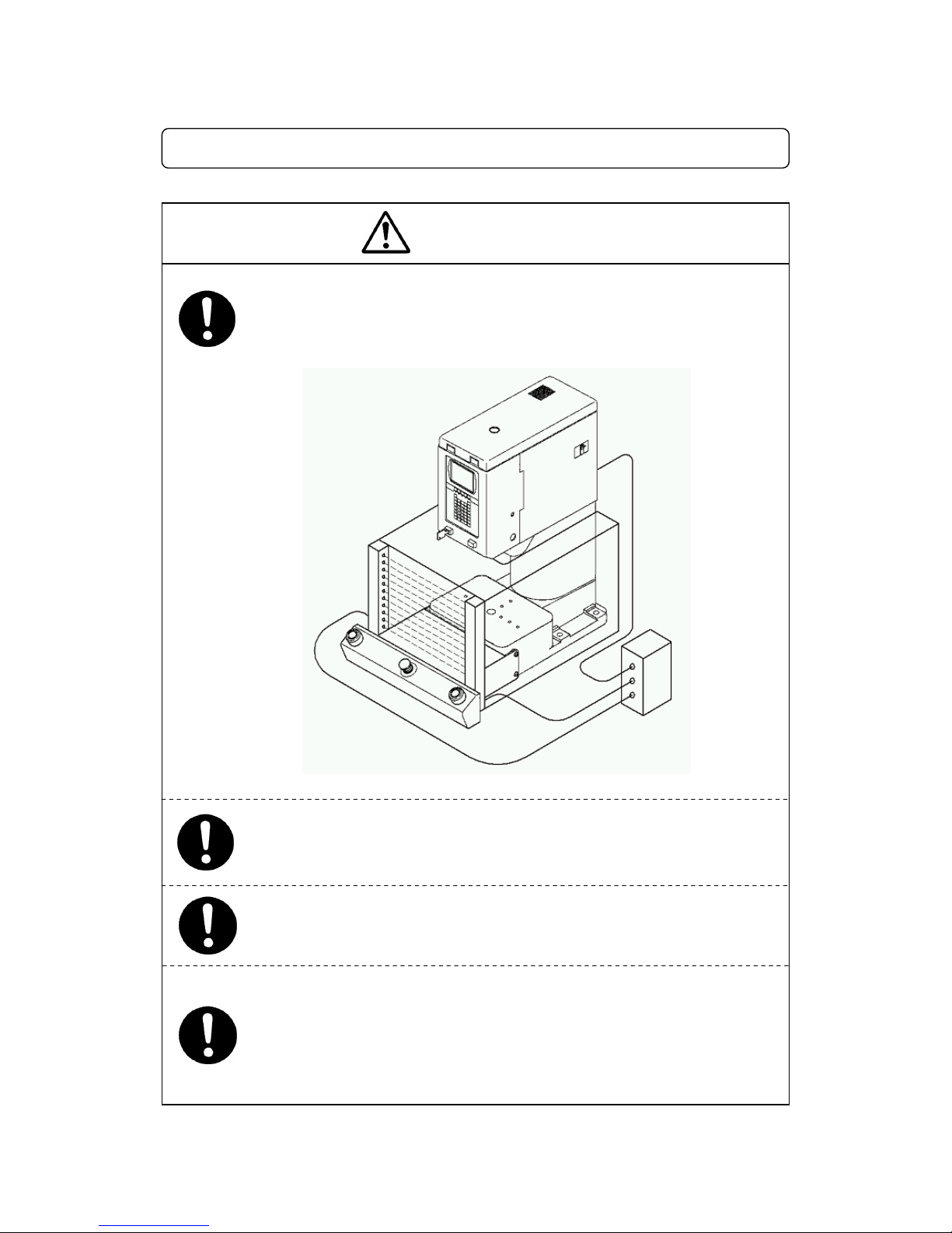
INSTALLATION
Install an interlock as a safeguard that triggers an emergency stop
when it is activated using the I/O-S connector included in the package.
Use protective wear (helmet, protective gloves, protective glasses and
protective footwear) when installing the machine.
Place the machine on a suitable flat surface that can support its weight
and do not cover the cooling fan vent on the top of a stand-alone and head
type.
An insufficient or unstable area can cause the machine to fall, overturn,
breakdown or overheat.
Place the machine in a well-ventilated area for the health and safety of
the operator.
<Example>
Warnings
Setup Electro Press JP Series 4 iii
FOR YOUR SAFETY
Keep the emergency stop switch within reach of an operator while
teaching and running the machine.
Failure to do so may cause danger since the machine cannot be stopped
immediately and safely.
Use the machine in an environment between 0 to 40 degrees
centigrade with a humidity of 20 to 95 percent without condensation.
Use outside tease conditions may result in malfunction.
IP Protection Rating is “IP40.”
Warnings
Turn off the unit before inserting and removing cables.
Failure to do so may result in electric shock, fire, or malfunction of the unit.
IP Protection Rating is “IP40.”
Confirm that the unit is properly grounded.
Power supply earth should be connected complying with Type D grounding.
(under 100 Ω of resistance.)
Insufficient grounding can cause electric shock, fire or malfunction.
Do not attempt to disassemble or modify the machine.
Disassembly or modification may cause electric shock, fire or malfunction.
Do not use the unit near inflammable or corrosive gas.
If leaked gas accumulates around the unit, it can cause fire.
IP Protection Rating is IP40.
Be sure to use within the voltage range indicated on the unit.
Failure to do so may cause electric shock or fire.
Plug the power cord into the wall outlet firmly.
Incomplete insertion into the wall outlet heats the plug and can cause fire.
Check that the plug is not covered with dust.
Be sure to shut off the power supply before connecting the power cord
Setup Electro Press JP Series 4 iv
FOR YOUR SAFETY
The installation mount should be steel. For the stand-alone type, it
should be able to support the machine’s weight. For the head and unit
types, it is able to support the machine’s weight and pressing capacity.
Use the machine in an environment that is not dusty or damp.
Dust and dampness may cause failure or malfunction.
Place the control box on a flat surface more than 80 cm above the floor so
that it is easier to operate it.
Attach an eyebolt and use a crane or other equipment to transport the
machine.
Failure to do so may result in malfunction or defect.
Do not bump or jar the machine while it is being transported or
installed.
This can cause defects.
Use the machine in an environment where it is not exposed to
direct sunlight.
Direct sunlight may cause malfunction or defect.
Be sure to confirm that jigs such as the electric screwdriver unit, etc.
are properly connected.
Failure to do so may result in injury or defect.
Be sure to check the wiring to the main unit.
Improper wiring may cause malfunction or defect.
Be sure to shut off the power supply before plugging the power cord.
Use the machine in an environment where no electric noise is
p
resent.
Warnings
Setup Electro Press JP Series 4 v
FOR YOUR SAFETY
WORKING ENVIRONMENT
Always be aware of the machine’s movement, even in the teaching mode.
Special attention will protect the operator from injury.
During operation, always have the emergency stop switch within the
operator’s reach.
For the operator’s safety, the emergency stop switch is necessary to make a
quick and safe stop in an emergency.
When you lubricate or inspect the unit, unplug the power cord from
the outlet.
Failure to do so may result in electric shock or injury.
Be sure to shut off the power supply before removing the power cord.
Warnings
Setup Electro Press JP Series 4 vi
FOR YOUR SAFETY
DURING OPERATION
During teaching, tests, and actual operation, always have the
Emergency stop switch within the operator’s reach.
For the operator’s safety, the emergency stop switch is necessary to
make a quick and safe stop in an emergency.
If anything unusual (e.g. a burning smell) occurs, stop operation and
unplug the cable immediately. Contact your dealer or the office listed
on the last page of this manual.
Continuous use without repair can cause electric shock, fire, or breakdown
of the unit.
Under no circumstances should you go inside the working area or
place your hands or head inside the working area while the machine is
operating.
When starting the machine, check that no object will interfere with the
machine’s operation.
Warnings
Setup Electro Press JP Series 4 vii
PREFACE
The operation manual for the JANOME Electro Press consists of the following volumes.
“For Your Safety” is also provided so that the customer can make the best use of this product safely.
This section includes preventive measures that can be taken against injury to the customer or damage
to property. Please be sure to read “For Your Safety” before using this product.
Setup
This volume explains how to set up the Electro Press.
* For those who have received training in Electro Press safety and installation.
Maintenance
This volume explains Electro Press maintenance.
* For those who have received training in Electro Press safety and installation.
Teaching and
Operation
This volume lists part names and data structure as well as providing the basic
knowledge necessary to operate the Electro Press.
Operation This volume explains how to operate the Electro Press.
Specifications
This volume provides comprehensive specifications, including mechanical and
electrical requirements.
Note: The product specifications in these volumes may differ from those of the machine you have
received due to a product upgrade.
Please be sure to follow the instructions described in these volumes. Proper use of the robot will
ensure continued functionality and high performance.
These volumes are based on the standard application. Menu items may vary depending on the
model.
Be sure to shut off the power supply before plugging in the power cord.
BE SURE TO MAKE A PROPER GROUNDING WHEN YOU INSTALL THE MACHINE.
Be sure to save data whenever it is added or modified. Otherwise, changes
will not be saved if the power to the robot is cut off.
Setup Electro Press JP Series 4 viii

CONTENTS
FOR YOUR SAFETY ______________________________________________________________ i
PREFACE_____________________________________________________________________ viii
CONTENTS ____________________________________________________________________ ix
1. ENVIRONMENT_______________________________________________________________ 1
Notice regarding Installation of the Electro Press ______________________________________ 2
2. SYSTEM CONFIGURATION _____________________________________________________ 3
2-1 Stand-Alone Type ___________________________________________________________ 3
2-2 Head Type ________________________________________________________________ 4
2-3 Unit Type__________________________________________________________________ 5
3. INSTALLATION _______________________________________________________________ 6
3-1 Lifting ____________________________________________________________________ 6
3-2 Setting____________________________________________________________________ 9
3-2-1 JP-104/JP-204, Stand-Alone Type ___________________________________________ 9
3-2-2 JP-504/JP-1004/JP-1504, Stand-Alone Type__________________________________ 10
3-2-3 JP-3004/JP-5004, Stand-Alone Type _________________________________________11
3-2-4 JPH-104/JPH-204, Head Type_____________________________________________ 12
3-2-5 JPH-504/JPH-1004, Head Type____________________________________________ 13
3-2-6 JPH-3004/JPH-5004, Head Type___________________________________________ 14
3-2-7 JPU-104/JPU-204, Unit Type ______________________________________________ 15
3-2-8 JPU-504/JPU-1004, Unit Type _____________________________________________ 16
3-2-9 JPU-1504, Unit Type ____________________________________________________ 17
3-2-10 JPU-3004/JPU-5004, Unit Type ___________________________________________ 18
3-2-11 JPU-8004, Unit Type ___________________________________________________ 19
3-3 Wiring ___________________________________________________________________ 20
3-3-1 Stand-Alone/Head Type __________________________________________________ 20
3-3-2 Unit Type _____________________________________________________________ 21
3-4 Base Dimensions __________________________________________________________ 25
3-4-1 JP-104/JP-204, Stand-Alone Type __________________________________________ 25
3-4-2 JP-504/JP-1004/JP-1504, Stand-Alone Type__________________________________ 26
3-4-3 JP-3004/JP-5004, Stand-Alone Type ________________________________________ 27
Setup Electro Press JP Series 4 ix

3-5 Ram Mounting Jig__________________________________________________________ 28
3-5-1 JP, JPH, JPU-104/204 ___________________________________________________ 28
3-5-2 JP, JPH, JPU-504/1004/1504______________________________________________ 29
3-5-3 JP, JPH, JPU-3004/5004, JPU-8004 ________________________________________ 30
3-5-4 Switching I/O-SYS and I/O-1 Power Supply___________________________________ 31
3-6 Safeguard Installation _______________________________________________________ 32
4. HOW TO BACK UP UNIQUE NUMBER AND INSTALL SETTING DATA __________________ 35
5. HOW TO INSTALL PRESS SYSTEM SOFTWARE ___________________________________ 36
6. TEACHING DATA BACKUP _____________________________________________________ 38
Setup Electro Press JP Series 4 x

1. ENVIRONMENT
■ Place the machine on a suitable flat surface that can support its weight.
Be sure to leave a space greater than 30cm between the back of the control box equipped with a
cooling fan and the wall. Do not cover the cooling fan vent on the top of a stand-alone or head
type press. An insufficient or unstable area can cause the machine to fall, overturn, breakdown,
or overheat.
■ If you use an installation mount, it should be able to support the machine’s
weight.
The installation mount should be steel. For the stand-alone type, it should be able to support the
machine’s weight. For the head and unit types, it should be able to support the machine’s
weight and pressing capacity.
■ Place the machine in a well-ventilated area for the health and safety of the
operator.
■ Do not use the machine near inflammable or corrosive gas.
If leaked gas accumulates around the machine, it can cause fire or explosion. IP Protection
Rating is “IP40.”
■ Use the machine in an environment between 0 to 40 degrees centigrade
with humidity of 20 to 95 percent without condensation.
Use outside these conditions may result in malfunction.
IP Protection Rating is “IP40.”
■ Avoid using any equipment emitting electric noise nearby.
Electric noise can cause the machine to break down.
■ Use the machine in an environment where it is not exposed to direct sunlight.
Direct sunlight may cause malfunction or defect.
■ Use the machine in an environment that is not dusty or damp.
Setup Electro Press JP Series 4 1

Notice regarding Installation of the Electro Press
When you install the Electro Press,
especially when mounting it on an automatic machine,
please be sure to follow the instructions below.
z Be sure to ground the Electro Press and other equipment securely. Keep grounding
resistance impedance as low as possible.
z
Use the shield for the I/O cable and make the wiring length as short as possible. Ground the
shield of the I/O cable.
z Wire the power supply cord separately from the I/O cable. Never bundle the power supply
cord and the I/O cable together.
z The wiring between the electric power system and the signal system in the distribution panel
should be isolated.
z Do not place or install any equipment emitting electric noise near the Electro Press. Use a
power source that supplies stable power.
Do not plug multiple cables into one electrical
outlet.
z
The load cell at the end of the ram should be periodically checked and, if necessary,
calibrated. When you install the Electro Press, leave enough space to allow load cell
calibration (for example by making the jigs under the ram detachable.)
z
Leave space between the Electro Press and wall or any other obstacle so that you can
remove the cover with a screwdriver when it is necessary to repair the unit. Also, leave
sufficient space at the side for the cooling fan to cool the unit.
z After completing the wiring of the Electro Press, confirm the wiring status using the following
procedure.
1. Select [Diagnosis Mode] from the maintenance mode menu.
2. Select [External I/O Diagnosis.]
IMPORTANT: For your safety, never disassemble or modify the Electro Press.
We are not liable for injury or damage caused by a modified Electro Press.
Switch Box
We suggest that you use our standard switch box (optional for the unit type.) If you use a
different switch box, be sure to use a shield wire in addition to the I/O cable.
If you want the switch box to be detached, state your request on the order sheet. We will equip
the Electro Press with a connector for the switch box at the rear of the unit.
Setup Electro Press JP Series 4 2
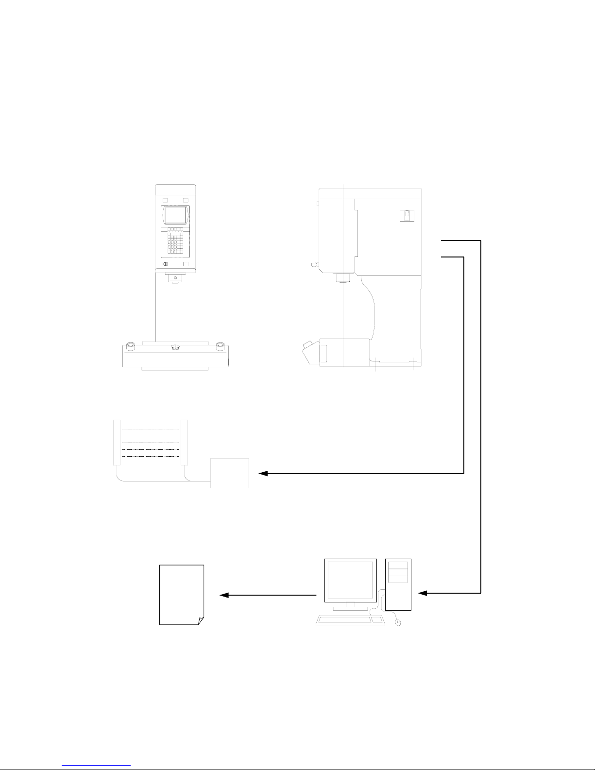
2. SYSTEM CONFIGURATION
2-1 Stand-Alone Type
The illustration shows the JP-504.
RS-232C Cable
(Not included in the package)
Front View
Electro Press
Area Sensor Connecting Cable
(Not included in the package)
Area Sensor
(Not ge) included in the packa
PC
Software for Windows (Optional)
Printer
Setup Electro Press JP Series 4 3
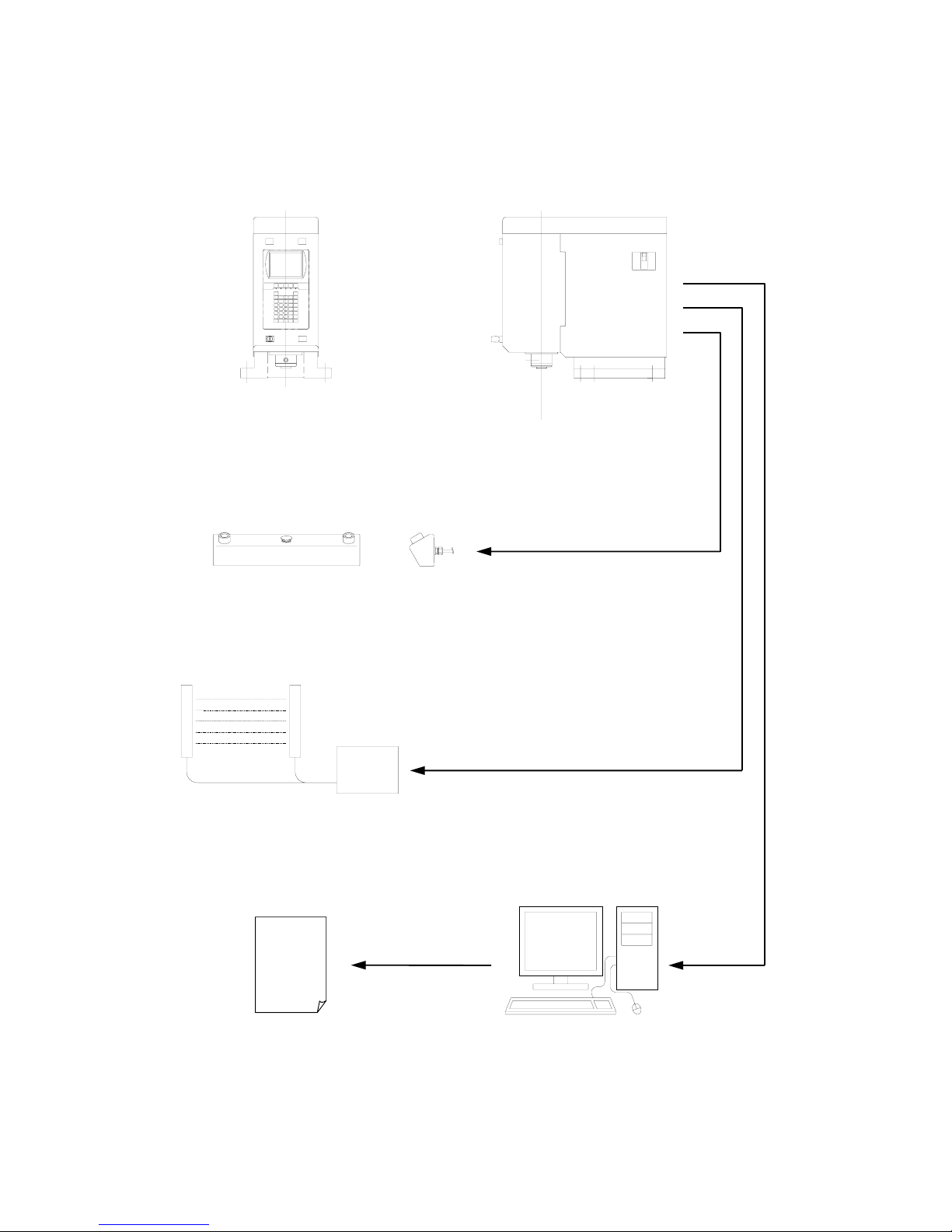
2-2 Head Type
The illustration shows the JPH-504.
RS-232C Cable
(Not included in the package)
Area Sensor Connection Cable
(Not included in the package)
Area Sensor
(Not included in the package)
Front View
Electro Press
Switch Box
3 m Cable
PC
Software for Windows (Optional)
Printer
Setup Electro Press JP Series 4 4
 Loading...