

Installation and Operating Data
FOR YOUR SAFETY - This product must be installed and serviced by authorized personnel, qualified in pool/spa heater installation. Improper installation and/or operation can
create carbon monoxide gas and flue gases which can cause serious injury, property
damage, or death. For indoor installations, as an additional measure of safety, Waterpik
Technologies strongly recommends installation of suitable Carbon Monoxide detectors in
the vicinity of this appliance and in any adjacent occupied spaces. Improper installation
and/or operation will void the warranty.
Installation and
Operation Manual
®
LX
and
®
LT
Low NOx*
Gas-Fired Pool
and Sp a Heater
Model LX/LT-Low NOx*
Natural Gas and LP
*Only models using natural gas are certified
as meeting low NOx emissions requirements.
WARNING
If these instructions are not followed exactly, a fire or explosion may result,
causing property damage, personal injury, or death.
Do not store or use gasoline or other flammable vapors and liquids in the
vicinity of this or any other appliance.
WHAT TO DO IF YOU SMELL GAS
• Do not try to light any appliance.
• Do not touch any electrical switch; do not use any phone in your building.
• Immediately call your gas supplier from a neighbor’s phone. Follow the gas
supplier’s instructions.
• If you cannot reach your gas supplier, call the fire department.
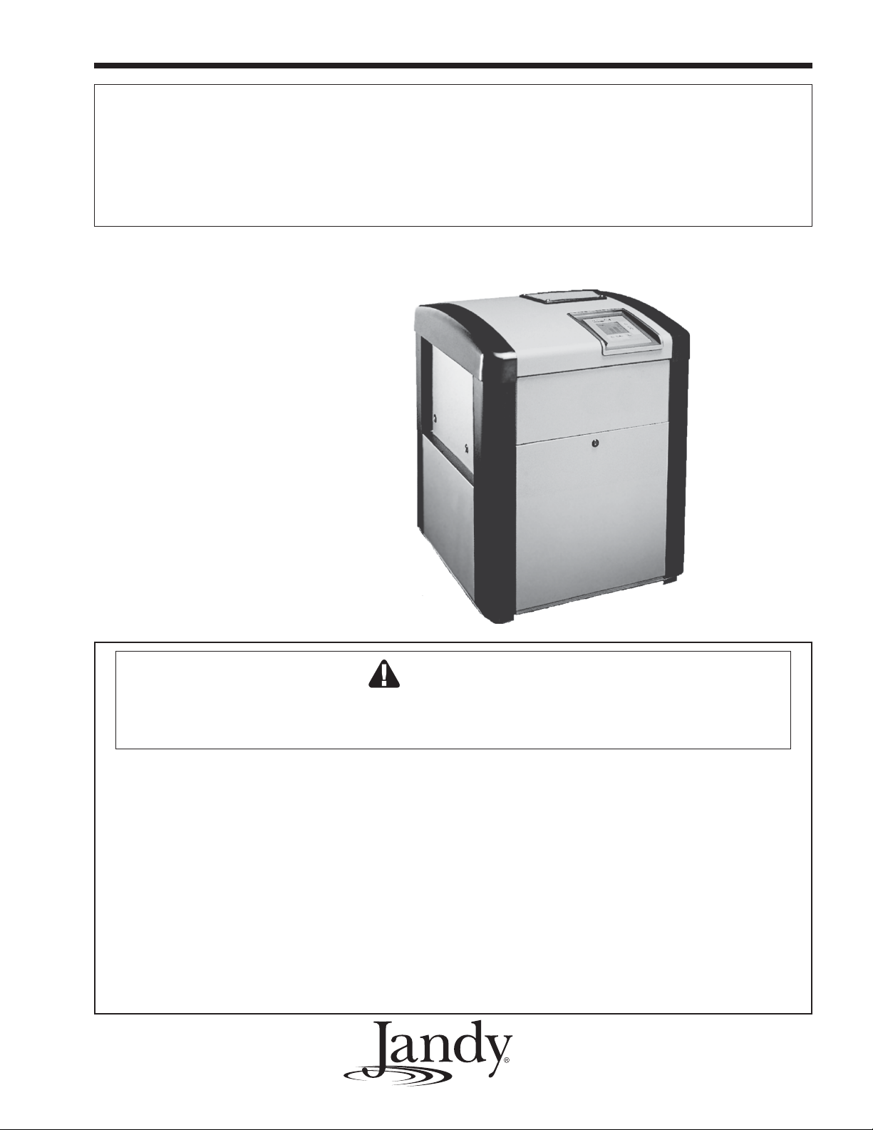
Model
LX250-L
Shown
Installation and service must be performed by a qualified installer, service
agency or the gas supplier.
H0256100E

TABLE OF CONTENTS
SECTION 1. General Information
1.1 Introduction .................................................1
1.2 Consumer Information and Safety................1
1.2.1 Spa/Hot Tub Safety Rules ...........................1
1.2.2 Swimming Pool Energy Safety Tips.............2
1.3 Warranty .....................................................2
1.4 Codes and Standards..................................2
1.5 Technical Assistance..................................3
1.6 Materials Installer Must Provide...................3
1.6.1 Materials for All Applications .......................3
1.6.2 Materials for Special Applications................3
1.7 Specifications..............................................3
1.7.1 General Specifications ................................3
1.7.2 Dimensions .................................................4
SECTION 2. Installation Instructions
2.1 Introduction .................................................5
2.2 Field Assembly ...........................................5
2.3 Location Requirements................................5
2.3.1 Introduction .................................................5
2.3.2 Clearances ..................................................5
2.3.3 Flooring .......................................................6
2.3.4 Outdoor Installation .....................................6
2.3.5 Indoor and Outdoor Shelter Installation ........7
2.3.5.1 Converting the Grill to a Vent Collar.............8
SECTION 3. Venting
3.1 Combustion Air Supply................................8
3.2 Exhaust Venting..........................................9
3.3 Vent Pipe Sizing and General Installation....1 0
3.3.1 Outdoor Installations ...................................10
3.3.2 Indoor and Outdoor Shelter Installations ......10
3.3.3 Inspection and Replacement of Existing
Vent System with New Components ...........11
SECTION 4. Gas Connections
4.1 Gas Supply and Piping................................11
4.2 Manifold Pressure .......................................12
4.3 Special Precautions for Propane Gas..........13
SECTION 5. Water Connections
5.1 Water Piping ...............................................13
5.2 Check Valve Installation ..............................13
5.3 Automatic Flow Control Valve......................13
5.4 Reversible Water Connections.....................14
5.5 Connections at Heater.................................16
5.6 Pressure Relief Valve ..................................17
5.7 Auxiliary Components, Chlorinators, Ozone
Generators, and Sanitizing Chemicals.........1 8
SECTION 6. Electrical
6.1 General Information .....................................18
6.2 Main Power .................................................18
6.2.1 Converting the Heater for a 115V
Power Source .......................................2 0
6.3 Bonding.......................................................20
6.4 Auxiliary Time Clock Wiring ........................21
6.5 Remote Operation .......................................21
SECTION 7. Operating Instructions
7.1 Normal Operation ......................................23
7.2 Start-Up ....................................................23
7.3 Temperature Controls ................................24
7.3.1 Information Displayed ................................24
7.3.2 Turning the Heater On or Off......................25
7.3.3 Setting Pool and Spa Temperatures,
Changing from Fahrenheit to Celsius....2 6
7.4 Lighting and Shutdown Procedures ...........26
7.4.1 Lighting the Heater ....................................26
7.4.2 Shut Down ................................................26
7.5 Adjusting the Water Pressure Switch........28
7.6 Temperature Rise ......................................29
SECTION 8. Maintenance
8.1 Water Chemistry.......................................30
8.2 Seasonal Care ..........................................30
8.2.1 Spring and Fall Operation..........................30
8.2.2 Winterizing................................................30
8.2.3 Spring Start-up..........................................31
8.3 Inspection and Service ..............................31
8.3.1 Owner Inspection ......................................31
8.3.2 Professional Inspection .............................32
SECTION 9. Troubleshooting
9.1 General Heater Troubleshooting Guide ......32
9.2 Service Codes ...........................................33
9.3 Ignition Control LED Service Codes ...........33
SECTION 10. Professional Maintenance
and Service
10.1 General Information ...................................36
10.2 "Premix" Induced Draft
Combustion System ..............................36
10.3 Special Service Issues
Premix Combustion System ..................37
10.3.1 System Operation .....................................37
10.3.2 Field Service and Adjustment....................37
10.4 Heater Components and Their Operation ...38
10.5 Electrical Trouble Shooting........................38
10.5.1 Electrical Power Supply ............................39
10.5.2 Controller ..................................................39
10.5.3 Control Circuit Trouble Shooting ................39
10.5.3.1 Transformer ...............................................40
10.5.3.2 Fuse .........................................................40
10.5.3.3 Water Pressure Switch/External Interlock
or Fireman Switch Circuit.....................40
10.5.3.4 Temperature Limit Switches Circuit ...........40
10.5.3.5 Fusible Link/Manual Reset Limit Switch
Circuit..................................................41
10.5.3.6 Blower Pressure Switch Circuit .................4 1
10.5.3.7 Gas Valve Voltage ....................................42
10.5.3.8 Igniter/Ignition Control Circuit.....................42
SECTION 11. Replacement Parts
11.1 Ordering Information ..................................46
11.2 Parts List ..................................................47
11.3 General Exploded View .............................48
11.4 Detailed Exploded View ............................49
Warranty .....................................Back Cover

LX and LT Low NOx Pool/Spa Heater Page 1
SECTION 1.
General Information
1.1 Introduction
This manual provides installation and operation
instructions for the LX and LT Low NOx pool and
spa heaters. Read these installation and operation
instructions completely before proceeding with the
installation. Consult the Jandy factory, or local
factory representative, with any questions regarding
this equipment.
Certain sections of this manual are specific to
either United States or Canadian installations, and are
labeled as such.
The LX and LT Low NOx heaters get their
electrical power from an external 115VAC or
230VAC source and provide a dual electronic thermostat control system for pool/spa combinations or
preheat convenience.
The LX and LT Low NOx heaters are specifically designed for heating fresh water swimming pools
and spas, and with proper installation and care, they
will provide years of reliable service. Do not use the
heater to maintain pool or spa water temperature
below 70°F. Do not use it as a heating boiler or
general service water heater or to heat salt water.
Consult your dealer for the appropriate Jandy products
for these applications.
In the LX and LT heaters, low NOx operation is
achieved through use of a special “premix” combustion
system. The operation of this type of system is affected by fuel gas properties. As noted in the troubleshooting and maintenance sections of this manual,
adjustments may be necessary if the local gas supply is
of especially high or low heat content.
1.2 Consumer Information and Safety
The LX and LT Low NOx heaters are designed
and manufactured to provide many years of safe and
reliable service when installed, operated and maintained according to the information in this manual and
the installation codes referred to in later sections.
Throughout the manual safety warnings and cautions
are identified by the "
comply with all of the warnings and cautions.
1.2.1 Spa/Hot Tub Safety Rules
The following “Safety Rules for Hot Tubs,”
recommended by the U.S. Consumer Product
Safety Commission, should be observed when
using the spa.
" symbol. Be sure to read and
WARNING
AVERTISSEMENT
Les Règlements suivants pour Cuves
Thermales, tel que recommandés par la
Commission U.S. de Sécurité des Produits
pour les Consommateurs, devraient être
respectés lors de l’utilisation du spa.
WARNING
The U.S. Consumer Product Safety
Commission warns that elevated water
temperature can be hazardous. Consult heater
operation and installation instructions for water
temperature guidelines before setting
temperature.
AVERTISSEMENT
La U.S. Consumer Product Safety Commission
indique que des températures de l'eau élevées
peuvent être dangereuses. Voir la notice
d'installation et de fonctionnement pour le
réglage de la température.
1. Spa or hot tub water temperature should never
exceed 104°F (40°C). One hundred degrees
Fahrenheit (100°F [38°C]) is considered safe for
a healthy adult. Special caution is recommended
for young children.
2. The drinking of alcoholic beverages before or
during spa or hot tub use can cause drowsiness
which could lead to unconsciousness, and
subsequently result in drowning.
3. Pregnant women take note! Soaking in water
above 102°F (38.5°C) can cause fetal damage
during the first three months of pregnancy (which
could result in the birth of a brain-damaged or
deformed child). If pregnant women are going to
use a spa or hot tub, they should make sure the
water temperature is below 100°F (38°C)
maximum.
4. The water temperature should always be
checked with an accurate thermometer before
entering a spa or hot tub. Temperature controls
may vary by as much as 1F° (1C°).
5. Persons with a medical history of heart disease,
diabetes, circulatory or blood pressure problems
should consult their physician before using a hot
tub or spa.
6. Persons taking any medication which induces
drowsiness (e.g., tranquilizers, antihistamines, or
anticoagulants) should not use spas or hot tubs.
7. Prolonged immersion in hot water can induce
hyperthermia.

Page 2
Hyperthermia occurs when the internal body
temperature reaches a level several degrees above the
normal body temperature of 98.6°F (37°C). Symptoms
include dizziness, fainting, drowsiness, lethargy, and an
increase in the internal body temperature. The effects
of hyperthermia include:
• Lack of awareness of impending hazard
• Failure to perceive heat
• Failure to recognize need to leave spa
• Physical inability to leave spa
• Fetal damage in pregnant women
• Unconsciousness resulting in a danger of
drowning
1.2.2 Swimming Pool Energy Saving Tips
Waterpik Technologies offers the following
recommendations to help conserve fuel and minimize
the cost of operating your pool heater without
sacrificing comfort.
1. The American Red Cross recommends a maxi-
mum water temperature of 78°F (25°C). Use an
accurate pool thermometer. A difference of 4F°
(2°C) , between 78°F and 82°F (26°C and 28°C),
will use as much as 40% more gas.
2. Carefully monitor the water temperature of your
pool in the summertime. You can reduce heater
usage due to warmer air temperatures.
3. Find the proper setting on the pool heater
temperature control and use the locking ring to
discourage further adjustments. (LT only).
4. Set the pump time clock to start the pump no
earlier than 6:00 AM during the pool heating
season. This is the time when nightly heat loss
balances.
5. If the pool is only going to be used on weekends,
reduce the heater temperature control setting by
8 or 10 degrees during the week. Reset it to the
78°F (25°C) level a day or so before you plan to
use the pool.
6. During the winter or when on vacation for longer
than a week, shut down the heater by following
the shutdown instructions found on the inside of
the heater.
7. Where possible, shelter the pool from prevailing
winds with well-trimmed hedges or other land-
scaping, cabanas, or fencing.
8. Always use a pool cover when practical. Besides
providing a valuable safety feature, a pool cover
will reduce heat loss, conserve chemicals, and
reduce the load on filter systems.
1.3 Warranty
The LX and LT Low NOx heaters are sold with
a limited factory warranty. Details are specified on the
back cover of this manual.
Make all warranty claims to an authorized Jandy
representative or directly to the factory. Claims must
include the heater serial number and model (this
information can be found on the rating plate), installation date, and name of the installer. Shipping costs are
not included in the warranty coverage.
The warranty does NOT cover damage caused
by improper assembly, installation, operation or field
modification. Also, damage to the heat exchanger by
corrosive water is NOT covered by the warranty. See
Section 8.1 for maintaining proper pool water chemistry.
NOTE: Keep this manual in a safe place for
future reference when inspecting or servicing
the heater.
1.4 Codes and Standards
The LX and LT Low-NOx pool and spa heaters
are design certified by CSA (Canadian Standards
Association) as complying with the latest edition of the
"Standard for Gas Fired Pool Heaters", ANSI Z21.56
in the USA and CAN-4.7 in Canada.
All Jandy heaters must be installed in accordance
with the local building and installation codes as per the
utility or authorities having jurisdiction. All local codes
take precedence over national codes.
In the absence of local codes, refer to the latest
edition of the following national codes for installation:
1. In the United States, "The National Fuel and Gas
Code", NFPA 54/ANSI Z223.1. Specifically,
refer to Part 7, "Venting of Equipment".
2. In Canada, "Natural Gas and Propane Installation
Code", CAN/CSA-B149.1.
The LX and LT Low NOx pool and spa heaters
exceed the requirements of energy conservation
regulations such as those in California, Hawaii, New
York, Oregon and other states which require that a
pool heater have intermittent ignition. In addition, the
natural gas models of this heater comply with both the
California South Coast Air Quality Management
District's (SCAQMD) rule 1146.2 and the Title 30,
Texas Administrative Code, Chapter 117, Section
117.465 for Nitrogen Oxide (NOx) emissions.

LX and LT Low NOx Pool/Spa Heater Page 3
Any changes to the heater, gas controls, gas
orifices, wiring, draft diverter, or improper installation
may void the warranty. If change is required to any of
the above, consult the factory.
1.5 Technical Assistance
Consult Waterpik Technologies or your local
Jandy distributor with any questions or problems
involving the specifications, installation, and operation
of your Jandy equipment. An experienced technical
support staff is ready to assist you in assuring the
proper performance and application of Jandy products.
For technical support call the Technical Service
Department at (707) 776-8200 extension 260.
1.6 Materials Installer Must Provide
1.6.1 Materials for All Applications
The following items are needed and are to be
supplied by the installer for
heater installations:
1. The correct size gas pipe to supply gas from the
meter to the heater (see Section 4.1 ).
2. A manually operated gas valve to be installed in
the gas line outside of the heater jacket.
3. A suitable gas union joint to connect the heater to
the gas line outside of the heater.
4. Plumbing items needed to provide a sediment
trap (drip leg) in the gas line between the manual
gas valve and the heater (see Section 4.1).
5. A 115V AC or 230V AC power supply. A
junction box is not needed at the heater, connec-
tions are made inside of the heater jacket.
1.6.2 Materials for Special Applications
In addition to the items listed above, the following items are needed for special applications.
1. A factory authorized vent collar and any vent
pipe needed for indoor installations in the USA
and outdoor shelter installations in Canada (see
Section 3.3.2). Vent collars are available from
any Jandy distributor.
all LX/LT Low NOx
1.7 Specifications
1.7.1 General Specifications
1. Installation Location:
Certified for use:
In the USA:
Natural Gas: Indoor and Outdoor
LP: Indoor and Outdoor
In Canada:
Natural Gas : Outdoor and Outdoor
Shelter
LP: Outdoor and Outdoor
Shelter
2. Minimum Clearance From Combustible Material:
See Table 2 in Section 2.3.2
3. *Gas Pipe/Heater Gas Valve Connection:
Natural Gas: 3/4" NPT
LP: 3/4" NPT
*
For diameter of gas line from meter to heater see
Table 5 in Section 4.1.
4. Supply Gas Type:
Certified for use with:
Natural gas and LP
5. Inlet Gas Supply Pressure:
Minimum Maximum
Natural Gas: 5.0 "WC 10.5 "WC
LP: 10.0 "WC 14.0 "WC
6. Water Pipe/Heater Connection:
*2" Unthreaded PVC or CPVC
*Other size pipes may be used. See Section
5.5 for details
7. Water Flow Rate:
Maximum: 125 gpm (475 lpm)
Minimum: 30 gpm (110 lpm)
8. Working Water Pressure:
Maximum: 75 psi
9. Exhaust Vent Connection Size:
Model:
250 7" Diameter
400 9" Diameter
2. Primer and cement suitable for cementing CPVC
pipe to PVC pipe and an appropriate coupling for
connecting the factory supplied CPVC pipe
nipples to PVC pool plumbing.
3. A non combustible platform for installation on
combustible surfaces (see Section 2.3.3). Non
combustible bases are available from your Jandy
distributor.
10. Electrical Supply:
Either 115 Volts AC or 230 Volts AC.
11. Modification of Heater for High Altitude:
LX and LT Low-NOx are normally shipped
from the factory in the low altitude (sea level)
operational configuration. When requested, the
heaters can be configured and shipped for higher
altitudes. For field conversions to change altitude
configurations, manifold kits for mid altitudes and

Page 4
high altitudes are available from your Jandy pool
products dealer or by contacting the Customer
Service Department at 707.776.8200 extension
245. See Section 11, "Parts List", of this manual
for the correct kit number for the manifold
assembly needed for your altitude. Table 1
defines the altitude designations as described by
the "Standard for Gas Fired Pool Heaters", ANSI
Z21.56 in the United States and "Gas-Fired
Appliances For Use At High Altitudes", CAN1-
2.17 in Canada.
1.7.2 Dimensions
See Figure 1 for a diagram showing the heater's
exterior dimensions and dimensions to critical connections on the heater.
Table 1. Altitude Designations For The LX/LT Heaters
NATURAL GAS
ALTITUDE UNITED CANADA
DESIGNATION STATES
LOW ALTITUDE 0-3000 FT 0-2000 FT
(0-610 m)
MID ALTITUDE 3001-6000 FT 2001-4500 FT
(611-1370 m)
HIGH ALTITUDE 6001-10,000 FT NOT
APPLICABLE
LP
LOW ALTITUDE 0-5000 FT 0-4500 FT
(0-1370 m)
HIGH ALTITUDE 5001-10,000 FT NOT
APPLICABLE
Heater Width
Model* Dim "A" Heater Depth Heater Height Vent Diameter Firing Rate
in (cm) in (cm) in (cm) in (cm) BTU/HR (kcal)
250-L 28 1/4 (72) 27 1/8 (69) 30 7/8 (78) 7 (18) 250,000 63
400-L 34 1/4 (87) 27 1/8 (69) 30 7/8 (78) 9 (23) 400,000 101
* Values shown are for both LX and LT models.
Figure 1. General Configuration

LX and LT Low NOx Pool/Spa Heater Page 5
SECTION 2.
Installation Instructions
2.1 Introduction
WARNING
Improper installation or maintenance can cause
nausea or asphyxiation from carbon monoxide
in flue gases which could result in severe injury,
or death. For indoor installations, as an
additional measure of safety, Waterpik
Technologies strongly recommends installation
of suitable Carbon Monoxide detectors in the
vicinity of this appliance and in any adjacent
occupied spaces.
AVERTISSEMENT
Une installation ou un entretien inadéquat peut
causer la nausée ou l’asphyxie en raison du
monoxyde de carbone présent dans les gaz de
combustion et même entraîner des blessures
graves ou la mort. Pour les installations
intérieures, comme mesure de sécurité
additionnelle, Waterpik Techonologies
recommande fortement l’installation de
détecteurs de monoxyde de carbone près de
cet appareil ainsi que dans les espaces
adjacents occupés.
Install the LX and LT Low NOx heaters and
vent collars in accordance with the procedures in this
manual, local codes and ordinances, and in accordance
with the latest edition of the appropriate national code
(see Section 1.4 "Codes and Standards").
All gas-fired products require correct installation
to assure safe operation. The requirements for pool
heaters include the following:
1. Field assembly (if required)
2. Appropriate site location (clearances) and
flooring
3. Sufficient combustion and ventilation air
4. Properly sized gas meter and piping
5. Proper electrical wiring (if required)
6. Adequate water flow
This manual provides the information needed to
meet these requirements. Review all application and
installation procedures completely before continuing
the installation.
Check the rating plate on the heater or the Parts
List (Section 11.2) of this manual for the correct Jandy
vent collar part number. For specific installation
information see Section 2.3.5 "Indoor and Outdoor
Shelter Installations".
Water connections are provided on the right side
of the heater but can be changed to the left side by
reversal of the heat exchanger. It is best to handle
these preparations before the heater is installed in its
final location. See Section 5.4 "Reversible Water
Connections" of this manual for instructions.
2.3 Location Requirements
2.3.1 Introduction
CAUTION
When pool equipment is located below the pool
surface, a leak from any component can cause
large scale water loss or flooding. Waterpik
Technologies cannot be responsible for such
water loss or flooding or resulting damage.
ATTENTION
Lorsque l’équipement d’une piscine est situé
sous la surface de l’eau, une fuite provenant de
n’importe quel élément peut causer une perte
d’eau importante ou une inondation. Waterpik
Technologies n’est pas responsable des pertes
d’eau, des inondations ou des avaries causées
par une installation ou un entretien inadéquat.
The LX and LT Low NOx heaters may be
installed indoors or outdoors as outlined in later sections. Location of the heater below or above the pool
water level affects operation of its water pressure
switch. See sections on water piping and heater startup for more information about this.
Avoid placing the heater in locations where it can
cause damage by water or condensate leakage. If this
is not possible, provide a suitable drain pan to catch
and divert any leakage. The pan must not restrict the
air flow around the heater.
All criteria given in the following sections reflect
minimum clearances as stated in the national standards. However, each installation must also be evaluated, taking into account the prevailing local conditions
such as wind speed and direction, proximity and height
of walls that may block ventilation, and proximity to
public access areas.
2.2 Field Assembly
The LX and LT Low NOx heaters can be
installed in a variety of ways, some of them requiring
preparation or assembly in the field. The heater is
shipped from the factory with an exhaust vent configured for an outdoor installation. The LX and LT Low
NOx heaters are also design certified for "Indoor"
installations in the United States and "Outdoor Shelter"
installations in Canada when equipped with a vent
collar and the appropriately sized exhaust vent.
2.3.2 Clearances
The heater must be placed to provide clearances
on all sides for maintenance and inspection. There
must also be minimum distances maintained from
combustible surfaces (see Table 2).
At least 18" (457mm) access must be available in
front of the heater for burner removal and access to
the igniter.
If the heater is to be installed in a garage, or

Page 6
Table 2. Minimum Heater Clearances From Combustible Surfaces
Table 2. Dégagements Minimaux à Assurer Entre les Parois de L'appareil et les Constructions Combustibles
SIDE OF INDOOR (OUTDOOR SHELTER) OUTDOOR INSTALLATION
HEATER INSTALLATION
INCHES CENTIMETERS INCHES CENTIMETERS
BLANK 4 10.2 4 10.2
REAR 4 10.2 4 10.2
PIPING 12 30.5 12 30.5
TOP 39 99.0 OPEN UNROOFED AREA
FRONT 18* 45.7 18* 45.7
similar structure, all burners and burner ignition
devices must have a minimum 18" (457mm) clearance
above the floor.
This heater must be installed at least 5 feet
(1.52m) from the inside wall of a pool unless the
heater is separated from the pool by a solid fence, wall
or other permanent solid barrier.
Ce chauffe-piscine doit être installé á au moins 5
pieds (1.52m) de la paroi interne de la piscine à moins
d'être isolé de la piscine par une clôture, un mur ou
autre barrière permanente.
Note: Clearances listed in T able 2 are
manufacturer's tested values. These are
given as minimum values. Where local
and national codes apply, and values are
different than those listed in Table 2,
use the greater value to ensure safe
operation.
* In Canada - 24 in (61cm)
2.3.3 Flooring
The heater must be installed on a level surface
of noncombustible construction or on fire-resistant
slabs or arches. Noncombustible flooring is defined as
flooring material and surface finish not capable of
being ignited and burning and with no combustible
materials against the underside. Acceptable materials
are those consisting entirely of a combination of steel,
iron, brick, tile, concrete, slate, glass or plaster. Do not
install the heater directly on a combustible wood or
carpet floor without placing a noncombustible platform
between the floor and the heater.
The heater can be installed on a combustible
floor if a noncombustible base assembly, available
from Jandy, is used. See the heater rating plate or the
Parts List (Section 11) of this manual for the appropriate base part number. Heaters must never be
installed directly on carpeting.
As an alternative to the Jandy noncombustible
base plate, in the United States, the National Fuel Gas
Code (NFPA 54 / ANSI Z223.1), and in Canada, the
Natural Gas and Propane Installation Code (CAN/
CSA-B149.1), allow a heater to be placed on a
combustible surface when there is a platform under
the heater made of hollow masonry no less than 4
inches (102 millimeters [mm]) thick, covered with
sheet metal at least 24 gauge thick and extending
beyond the full width and depth of the heater by at
least 6 inches (153 mm) in all directions. The masonry
Notes:
1. Blocks must provide a solid base and be braced so they
cannot slip out of place.
2. Air openings in blocks must be arranged to provide
unrestricted opening through entire width or length of
base.
3. Sheet metal must be at least 24 ga. and extend 6"
beyond the heater jacket on all sides.
Figure 2. Non-Combustible Platform
must be laid with ends unsealed, and joints matched to
provide free circulation of air from side to side through
the masonry (see Figure 2). If the heater is installed in
a carpeted alcove, the entire floor of the alcove must
be covered by a noncombustible panel.
2.3.4 Outdoor Installation
The LX or LT Low NOx heaters can be installed
in the outdoor configuration as received from the
factory.
Locate the heater in an open, unroofed area. Do
not install the heater under a deck. Do not locate the
heater below or adjacent to any doors, glass openings,
louvers, grills, etc., which connect in any way with an
inhabited area of a building, even though the access
might be through another structure (e.g., a garage or

LX and LT Low NOx Pool/Spa Heater Page 7
utility room). In the United States there must be a
minimum of four (4) feet (1.22 m) horizontally and
four (4) feet (1.22 m) vertically between the heater
exhaust point and any door, glass opening, or gravity
inlet to a building. In Canada, the heater must be
installed so that the exhaust point of the heater is at
least ten (10) feet (3.0 m) from any building opening
(see Figure 3).
WARNING
United States
Do not install the heater with the top of the vent
assembly within 4 feet (1.22 m) horizontally and
4 feet (1.22 m) vertically of any opening into a
building.
Canada
Do not install the heater with the top of the vent
assembly within 10 feet (3.05 m) of any
opening into a building.
AVERTISSEMENT
Lorsque vous installez l’appareil de chauffage,
assurez-vous que l’ouverture d’aération se
trouve à un minimum de 10 pieds (3,05 m) de
toute ouverture d’un bâtiment.
The top surface of the heater must be at least
three(3) feet above any forced air inlet, or intake ducts
located within ten(10) feet horizontally.
If the heater is installed under an overhang, there
must be a minimum clearance of 5 feet (1.5 m) above
the top of the heater and the structure should not
overhang the heater more than 12 inches (0.30m). The
area under the overhang must be open on three sides.
This prevents combustion gases from being diverted into
living areas through doors, windows, or gravity inlets.
Ne pas installer ce chauffe-piscine sous une
saillie mesurant moins de 3 pi de hauteur. La partie
sous la saillie doit être ouverte sur 3 côtés.
If the heater is installed close to a structure,
protect it from rain water runoff with rain gutters on
the roof or other measures. Do not locate the heater
near irrigation sprinkler systems that could spray
water on it. Water from sprinklers may cause damage
to controls and electronic components.
Avoid locations where wind deflection off
nearby structures might cause downdraft conditions.
Where downdraft conditions exist, locate the heater at
least 3 feet (0.91 m) from vertical surfaces (e.g.,
nearby buildings and walls).
In Florida it is required that the heater be securely fastened to the equipment pad. Use a size
1/4" x 1-1/2" long stainless steel Tapcon® type concrete screws and washers at each of the four tabs
located at the base of the heater. Mounting the
appliance in this manner meets the applicable requirements of the Florida Building Code.
Mounting screws are not provided with this
heater. After placing the heater on the equipment pad,
drill a hole in the concrete at each of the four tabs on
the feet of the heater. (The correct size drill bit is
usually provided with the concrete screws when
purchased). Place a screw in each of the holes and
fasten the heater to the equipment pad (see Figure 4).
Do not over torque the screws.
Figure 3. Outdoor Heater Installation
Figure 4. Anchor Heater To Equipment Pad
2.3.5 Indoor and Outdoor Shelter
Installations
An outdoor shelter (Canada only) is an unoccupied enclosure which does not communicate directly
with occupied areas. All indoor installations and
outdoor shelter installations require the addition of a
factory approved vent collar. The vent collar must be
installed without modification and in accordance with
the instructions provided by the manufacturer.

Page 8
Une remise extérieure (au Canada seulement)
est un endroit inoccupé qui ne communique pas
directement avec les endroits occupés. Toutes les
installations intérieures et remises extérieures exigent
l’addition d’une cheminée approuvée par le
manufacturier. La cheminée doit être installée sans
aucune modification et selon les exigences fournies
par le manufacturier.
These codes, standards and Waterpik Technologies require that the heater be properly vented as
outlined in this manual. Proper ventilation of exhaust
and combustion air are essential for the safe and
efficient operation of the heater (See Section 3).
OUTDOOR
VENT GRILL
2.3.5.1 Converting the Grill to a Vent
Collar
If the LX or LT Low NOx is to be installed
either indoors or in an outdoor shelter, its exhaust
discharge grill must be converted to a collar for vent
pipe connection. The necessary vent collar, gasket and
screws can be ordered as parts kit R0331403 for
model 250 or R0331405 for model 400 (see parts list in
Section 11 of this manual). The conversion can be
done quite simply as follows:
1. Remove the vent exhaust grill by removing the
four screws which retain it. The grill and the
screws may be discarded (See Figure 5).
2. Replace the grill with the vent collar. Place the
vent collar and gasket over the hole and fasten it
in place with the 4 screws provided. Be sure that
all components are properly aligned
(See Figure 6).
Figure 5. Removal of Outdoor Exhaust Grill
INDOOR
VENT
COLLAR
GASKET
Figure 6. Vent Collar Assembly for Indoor and Outdoor
Shelter Installation
Figure 7. Vent Pipe Installation
3. Install the vent pipe on the indoor vent collar. The
collar will accommodate vent piping of nominal 7"
or 9" diameter (see Table 4), depending upon the
model of your heater (See Figure 7). See vent
installation section for important information on
selecting proper pipe size.
SECTION 3.
Venting
3.1 Combustion Air Supply
The heater location must provide sufficient air
supply for proper combustion and ventilation of the
surrounding area as outlined in the latest edition of
ANSI standard Z223.1 or in Canada, CAN/CSAB149.1, and any local codes that may be applicable.
In general, these requirements specify that the
room in which a heater is installed should be provided
with two permanent air supply openings; one within 12
inches (305mm) of the ceiling, the other within 12
inches (305mm) of the floor. All indoor installations
must have openings to outside air for combustion,
ventilation, and dilution of flue gases from inside the
building (see Figure 7 and Table 3). Waterpik Technologies does not recommend indoor installations that
do not provide combustion air from outside the building.
All outdoor shelter installations (Canada only)
must have uninterrupted openings to outside air for
combustion and ventilation. The installation must be in
accordance with the latest edition of CAN/CSA B149.
Waterpik Technologies does not recommend outdoor
shelter installations that depend on internal air for
combustion. Combustion air should be ducted to the
heater from outside the structure.

LX and LT Low NOx Pool/Spa Heater Page 9
Notes:
1. Use approved
roof jack.
3)
Figure 8. Indoor Installation Venting (USA), or Outdoor Shelter (Canada)
Table 3. Air Openings to Outside
Required Net Free Open Area*
for Combustion Air Openings
Direct from outside Duct from outside
Model in
250-L 63 (406) 126 (813)
400-L 100 (645) 200 (1290)
*Area indicated is for one of two openings; one at floor level
and one at the ceiling, so the total net free area would be double
the figures indicated. For special conditions, refer to NFPA54
ANSI Z223.1. In Canada refer to the National Standard CAN/
CSA-B149.1 which differs from this table.
Note: If using screens and/or metal louvers, compensate by adding
50% additional area to each opening
If using wood louvers each opening must be at least four times
the area indicated in the table above.
2
(cm2)in2(cm2)
Outside Air Supply: When combustion air is
supplied directly through an outside wall, each opening
should have a minimum free area of one square inch
per 4,000 BTU/h (1.2kW) input of the total input rating
of all appliances in the enclosed area. If air is provided
through horizontal ducts, each opening and duct must
provide one square inch of flow area for each 2000
BTU/h (0.6 kW). These requirements are summarized
in Table 3. Note that the areas specified are net free
areas and should be increased when the openings are
covered by screens, louvers, grills or other protective
covers (see Figure 8 and Table 3 notes).
Note: In Canada, follow Canadian Standard,
CAN/CSA-B149.1 or local codes.
Exhaust Fans or Vents: Any equipment which
exhausts air from the room where the heater is
installed can deplete the combustion air supply or
reverse the natural draft action of the venting system.
This could cause flue products to accumulate in the
room. Additional air must be supplied to compensate
for such exhaust.
The information in Table 3 is not applicable in
installations where exhaust fans or blowers of any type
are used. Such installations must be designed by
qualified engineers.
The heater must be completely isolated and
protected from any source of corrosive chemical
fumes such as those emitted by trichlorethylene,
perchloroethylene, chlorine, etc.
WARNING
Do not store any chemicals, cleaners, or other
corrosive material near combustion air
openings or in the room. Avoid locating
appliance vents in the vicinity of combustion air
openings. Failure to prevent corrosive materials
from mixing with combustion air can result in
reduced heater life and unsafe heater
operation.
AVERTISSEMENT
Ne pas entreposer ni utiliser d'essence ni
d'autres vapeurs ou liquides inflammables à
proximité de cet appareil ou de tout autre
appareil.
3.2 Exhaust Venting
When converted to indoor and outdoor shelter
venting configuration, the LX and LT Low NOx
heaters have a vent collar fitting. The diameter of the
vent collar and, thus, the minimum diameter of the vent
pipe to be used is determined by the model of heater
installed. The only correct procedure for vent pipe
sizing is to do so in accordance with Table 4 and
the applicable installation code as stated in the
following "Danger" warning.

Page 10
Table 4. Vent Pipe Sizing Table
LX/LT Vent Pipe Diameter
Low NOx
Model inch cm
250-L 7.0 17.8
400-L 9.0 22.9
WARNING
Vent pipe diameter must be as required by the
National fuel Gas Code Z223.1 or the Canadian
Installation Codes for Gas Appliances CAN/
CSA-B149.1. Undersize pipe can result in
inadequate venting and oversize pipe can result
in vent condensation. In either case the result
can be release of combustion products to the
indoors. This can cause serious injury or death
by carbon monoxide poisoning or asphyxiation.
AVERTISSEMENT
Le diamètre des tuyaux de ventilation doit
répondre aux exigences du National Fuel Gas
Code Z223.1 ou du code canadien des
installations des appareils à gaz CAN/CSA
B149.1. Des tuyaux trop petits risquent
d’entraîner une ventilation inadéquate et des
tuyaux trop gros risquent de provoquer une
condensation dans les tuyaux. Dans un cas
comme dans l’autre, des produits de
combustion risquent de s’échapper dans le
bâtiment et causer des blessures graves ou
l’asphyxie par le monoxyde de carbone.
3.3 Vent Pipe Sizing and General
Installation
As part of their certification, the LX and LT Low
NOx heaters have been determined to be a Category 1
Fan-Assisted appliance. They are intended for standard vertical venting per tables provided in most local
codes for Category 1 Fan-Assisted appliances. If the
local code does not include such tables, refer to the
National Fuel Gas Code NFPA 54 / ANSI Z223.1 or
the Canadian Installation Codes for Gas Appliances
CAN/CSA-B149.1. Note that the tables for fanassisted appliances include both maximum and minimum vent loading figures. The primary purpose of the
maximum ratings are to assure that the vent operates
with negative pressure throughout its length. The
minimum ratings are to assure that vent gases don’t
cool too much and thereby assure that condensation
doesn’t occur.
3.3.1 Outdoor Installations
For outdoor installations, exhaust venting consid-
erations will determine the placement of the heater
(See Section 2.3.4). If the heater cannot be placed so
as to meet the requirements stated in Section 2.3.4, a
vent collar may be added to the heater to move the
exhaust vent opening to a position that complies with
the requirements. In all cases, vent collars must be of
the same diameter as the exhaust outlet of the heater.
Approved vent collars may be obtained through your
Jandy distributor.
3.3.2 Indoor and Outdoor Shelter
Installations
All indoor installations and outdoor shelter
installations require the addition of a factory approved
vent collar. The vent collar must be installed without
modification.
All vent installations must be made in accordance with all local, state or provincial codes and with:
1. Chapter 7, " Venting of Equipment" of the
national Fuel Gas Code, ANSI 223.1 latest
edition, or the applicable provisions of the local
building codes.
2 In Canada, CAN/CSA B149.1.
Avoid terminating heater vents near air conditioning or air supply fans. The fans can pick up
exhaust flue products from the heater and return them
inside the building, creating a possible health hazard.
Do not locate the vent terminal where flue
products could strike against building materials and
cause degradation.
Vent opening should be well away from trees or
other obstructions that would prevent free air flow to
and from vent terminal. Do not terminate the vent
under decks, stairways, or car ports.
Be sure to support all venting so that connections
will not separate and so that the weight of the vent
pipe does not rest on the heater vent collar. All
connections should be made with rustproof sheet
metal screws. Do not weld or fasten the vent pipe to
the heater vent collar. The vent collar and heater top
must be easily removable for normal heater service
and inspection.
The vent collar outlet is to be connected to an
unobstructed vent pipe of the same diameter, terminating outside the building. The vent must terminate at
least two (2) feet (0.6 m) above the highest point of
the roof or other object that is within ten (10) feet (3.0
m) of the vent termination. The vent pipe must have a
listed vent cap which allows a full equivalent opening
for flue products (see Figure 7).
Type “B” double wall or equivalent vent pipe is
recommended. However, single wall metal vent pipe
may be used as specified in the latest edition of the
National Fuel Gas Code ANSI Z 223.1 or in Canada
CAN/CSA-B149.1.
IMPORTANT NOTE: Do not use sheet metal
screws at the snap lock joints of Type B gas
vents.
When venting multiple appliances through one
common duct, each appliance must have it's own vent
temperature limit switch. All vent limit switches must
be wired in series so as to prevent any appliance from
firing in the event of a blocked vent. Refer to ANSI
Z223.1 or, in Canada, to CAN/CSA B149.1 for more
information on multiple venting.

LX and LT Low NOx Pool/Spa Heater Page 11
3.3.3 Inspection and Replacement of
Existing Vent System with New
Components
If the LX/LT is being installed to replace an
existing pool heater, it is recommended that a new
appropriate venting system be installed with the new
heater. However, if an existing venting system must be
used, be sure to carefully inspect the venting system to
ensure that it is in good condition and continues to be
appropriate for the LX/LT heater. Replace any parts
that are not in good and serviceable condition with new
parts before completing the pool heater installation.
SECTION 4.
Gas Connections
4.1 Gas Supply and Piping
Review the following general instructions before
continuing the installation.
WARNING
The LX and LT Low-NOx pool and spa heaters
are designed for use with either natural gas or
LP gas. Check the rating plate on the inner
panel to be sure that the heater is designed to
use the type of gas being supplied. DO NOT
ATTEMPT TO CONVERT THIS HEATER
FOR USE WITH ANY OTHER TYPE OF
FUEL.
AVERTISSEMENT
Les appareils de chauffage à faibles émissions
NOx LX et LT pour piscines et cuves thermales
sont conçus pour être utilisés avec du gaz
naturel ou du gaz de pétrole liquéfié (GPL).
Vérifiez l’information inscrite sur la plaque
signalétique du panneau intérieur pour vous
assurer que l’appareil est conçu pour le type de
gaz fourni. NE PAS ESSAYER DE
CONVERTIR CET APPAREIL À UN AUTRE
TYPE DE GAZ.
1. Gas piping installation must be in accordance
with the latest edition of ANSI Z223.1 and all
local codes. In Canada, the installation must be in
accordance with CAN/CSA B149.1 and all local
codes that apply.
correct part number of the manifold kit needed.
When changing the altitude range of the heater,
be sure to fill out the altitude conversion label,
included in the kit. Apply the label on the inner
panel of the heater, next to the original rating
plate.
CAUTION
Permanent damage to the gas valve will occur
if the following procedures are not followed.
ATTENTION
Vous endommagerez la soupape de gaz si
vous ne respectez pas les procédures
suivantes.
3. Use the figures in Table 5 to size the gas inlet
piping from the gas meter to the heater. Check
all local codes for compliance before installing
the heater.
Table 5. Supply Gas Pipe Size Requirements*
Distance from Gas Meter
0-50 feet 50-100 feet 100-200 feet
Heater (0-15 m) (15-30 m) (30-60 m)
Size in. (mm) in. (mm) in. (mm)
250 1 (25) 1-1/4 (32) 1-1/4 (32)
400 1-1/4 (32) 1-1/2 (38) 1-1/2 (38)
Notes:
*
1. These numbers are for natural gas (0.65 Sp. Gr.) and are
based on 1/2 inch (3.45 kPa) water column pressure
drop. Check supply pressure with a manometer, and
local code requirements for variations. For LP gas,
reduce pipe diameter by one size, but maintain a
minimum 3/4 " diameter.
2. Check supply pressure and local code requirements
before proceeding with work.
3. Pipe fittings must be considered when determining gas
pipe sizing.
4. Install a sediment trap (drip leg) ahead of the gas
controls (see Figure 9). Fit the trap with a
threaded cap which can be removed for cleaning.
APPROVED
2. Check the gas supply to be sure that it is the
same as the gas indicated on the heater's rating
plate. LX and LT Low NOx heaters, as shipped
from the factory, are certified to operate within
the altitude range indicated on the rating plate. If
a field conversion to a different altitude range
should be necessary, manifold kits are available
for changing the altitude range of the heater. See
Table 1 on page 4 of this manual to determine the
correct altitude designation for your heater.
Refer to Section 11 "Parts List" to order the
Figure 9. Proper Design for a Sediment Trap/Drip Leg

Page 12
5. Install a manual gas shutoff valve for service and
safety. Do not use a restrictive gas cock. DO
NOT USE FLEXIBLE GAS PIPING, it will
restrict the gas flow to the heater.
6. Disconnect the heater and its individual shutoff
valve from the gas supply system during pressure
testing of the system at pressures higher than 1/2
pounds per square inch (psi) (3.45 kilopascals
[kPa]). If the test pressure is equal to or less
than 1/2 psi (3.45 kPa), close the manual shutoff
valve on the heater during the piping pressure
test.
7. If the gas supply pressure is less than required,
check for undersized pipe between the meter and
the heater, a restrictive fitting, or an undersized
gas meter. Gas supply pressures to the heater
are listed in Table 6.
Table 6. Gas Supply Pressure Requirements
Supply Pressure Minimum Maximum
Natural Gas 5.0 Inches WC 10.5 Inches WC
(1.2 kPa) (2.6 kPa)
LP Gas 11.0 Inches WC 14.0 Inches WC
(2.5 kPa) (3.5 kPa)
Manifold Pressure Nominal
Natural Gas 3.0 Inches WC (1.0 kPa)
LP Gas 9.0 Inches WC (2.2 kPa)
NOTE: The maximum inlet gas pressure must
not exceed the specified value. The minimum
value listed is for the purpose of input
adjustment. Refer to Table 6.
8. To connect the gas supply line to the heater's gas
valve, make sure the steel elbow (supplied with
the manifold) is screwed into the inlet side of the
gas valve. The heater is designed so that the gas
supply line may enter through either side of the
heater. Hand tighten the elbow until the desired
orientation is achieved.
CAUTION
Do not overtighten the elbow. Over tightening
will crack the gas valve. Do not use teflon tape
to wrap the elbow threads.
ATTENTION
Ne serrez pas trop le coude. Vous risqueriez
de fissurer la soupape de gaz. N’entourez pas
le filetage des coudes de ruban à joints.
9. Before operating the heater, test the complete
gas supply system and all connections for leaks
using a soap solution. Do not use an open flame.
CAUTION
Some leak test solutions (including soap and
water) may cause corrosion or stress cracking.
Rinse the piping with water after testing.
ATTENTION
Certaines solutions d’essai d’étanchéité (y
compris l’eau et le savon) peuvent causer de la
corrosion ou de la fissuration. Rincez les
tuyaux à l’eau après l’essai d’étanchéité.
4.2 Manifold Pressure
Confirm that gas supply pressure is correct. If
the gas supply pressure is less than required, check for
undersized pipe between the meter and the heater, a
restrictive fitting, or an undersized gas meter. Gas
supply pressures to the heater, when it is operating,
are listed in Table 6.
CAUTION
Manifold gas pressure for the LX and LT Low
NOx natural gas heaters should be set at 3"
WC. Propane heaters should be set to 9" WC.
ATTENTION
La pression du collecteur de pression pour les
systèmes de chauffage au gaz naturel devrait
être de 3'’ WC. Pour les sytèmes de chauffage
au gaz propane devrait être de 9'’ WC.
The manifold pressure may be checked by
connecting a manometer to the pressure port on the
outlet side of the valve. The pressure will be zero
when the heater is not running. When the heater is
operating the manifold gas pressure should be 3.0" WC
for natural gas heaters and 9.0" WC for LP gas
heaters. To adjust the manifold gas pressure, first
remove the slotted cap next to the inlet pressure port
on the inlet side of the gas valve. Under the slotted
cap is a slotted plastic screw which increases the
manifold pressure when turned clockwise and decreases the manifold pressure when turned counterclockwise. After measurements, and adjustments if
necessary, have been made, make sure to replace the
1/8" NPT gas valve plugs on the inlet and manifold
pressure ports, and the cap on the manifold pressure
adjustment screw. It is extremely important to replace
these parts before leaving the installation. Failure to
do so can result in damage to property or injury or
death. With the heater firing, the pressure must be
within the range shown in Table 6. Also check the
pressure with the heater off.

LX and LT Low NOx Pool/Spa Heater Page 13
Figure 10. Typical Piping Installation
4.3 Special Precautions for LP Gas
LP Gas is heavier than air and can therefore
more readily collect or “pool” in enclosed areas if
provision for proper ventilation is not made. Installation
of pool heaters in enclosed areas such as pits is not
recommended. However, if such an installation is
required be sure to pay special attention to proper
ventilation for LP gas. Locate heaters a safe distance
from LP gas cylinders and filling equipment. Consult
the National Fuel Gas Code (NFPA 54 / ANSI
Z223.1, latest edition), the Natural Gas Installation
Code in Canada (CAN/CSA B149.1, latest edition),
and any other local codes and fire protection authorities about specific installation restrictions in your area.
SECTION 5.
Water Connections
5.1 Water Piping
Figure 10 illustrates typical piping for pool
equipment in pool/spa combination pools. With its
electronic control, the LX and LT Low NOx heaters
are particularly suited for this type of pool installation.
The heater must be protected from backsiphoning of water, which can result in dry starts. If
there is any chance of back-siphoning, provide a check
valve between the pool and the filter pump inlet.
Arrangement of pool system components other
than as illustrated in these diagrams can affect the
operation of the heater’s water pressure switch.
Location of the heater above or below the pool water
surface can also affect operation of the switch. In
general, the pressure switch can be adjusted to
accommodate this effect if the heater water connections are no more than six feet below the pool water
surface and no more than 15 feet above it. See
instructions for pressure switch adjustment (Section
7.5) for more information about this.
Note that when pool equipment is located below
the pool surface a leak can result in large scale water
loss or flooding. Waterpik Technologies cannot be
responsible for such water loss or flooding or the
damage caused by either occurrence.
5.2 Check Valve Installation
Install a check valve in the plumbing between
the pool inlet and the heater if there is any chance of
back-siphoning.
Do not install any valve in the piping between the
heater outlet and the pool, unless it is being used as a
diverter valve. For special installations such as water
connections below the water level of the pool, or for
other questions contact the Technical Service department at (707) 776-8200 ext. 260.
5.3 Automatic Flow Control Valve
The inlet/outlet header of the LX and LT Low
NOx heater comes equipped with an automatic flow
control valve. The automatic flow control valve
maintains the proper flow through the heater at rates
up to approximately 125 Gallons Per Minute (GPM)
(475 liters per minute [LPM]). If the filter system
flow rate is higher than approximately 125 GPM (475
LPM), install a manual bypass valve (see Figure 9),
then perform a temperature rise test (see Section 7.6)
and adjust the flow using the bypass valve until the
proper temperature rise is obtained.
Page 14
5.4 Reversible Water Connections
The LX and LT Low NOx heaters are shipped
with water connections on the right side, but they can
be modified in the field to provide left-side water
connections. This procedure involves removing the
heat exchanger headers and reinstalling them on
opposite ends of the tube assembly. Some of the
heater wiring and control components must be relocated, so this procedure must be done only by a trained
service technician.
Heat exchanger reversals are generally done
before the installation of power and water to the
heater. If you need to reverse the heat exchanger on a
previously installed heater be sure that all electrical
power, the gas supply and water supply have been
turned off before starting the procedure. These
instructions have been written to include the steps
needed when reversing the water connections on an
existing installation. If you are reversing the headers
on a new installation, some steps will be ignored.
Water connection reversal is illustrated in Figures 11
and 12 . Proceed as follows:
1. For an existing installation, drain the heater by
removing the drain plug on the inlet/outlet header
and the two drain plugs on the return header.
2. Remove the heater front panel (door).
3. Remove the two hex head screws that hold the
raceway cover in place. They are located on the
bottom flange of the raceway cover. Slide the
raceway cover down to expose the raceway.
4. Remove the control panel assembly from the top
panel (see figure 13 for panel identification). Lift
the control panel cover. Remove the two philips
head screws located at the front edge of the
bezel. Lift the front of the bezel up until the entire
assembly comes away from the top. Without
removing any wires, slip the control assembly
through the hole so that when the top is removed,
the control assembly will stay with the heater.
GRILL
TOP
PANEL
CONTROL
PANEL
Figure 11. Water Connections as Shipped
I/O HEADER SIDE
REAR
PANEL
RETURN
HEADER SIDE
COVER PLATE
UPPER
LEFT SIDE
PANEL
LEFT
SIDE COVER
PANEL
Figure 13. LX/LT Panel Identification
COVER PLATE
UPPER
RIGHT SIDE
PANEL
RACEWAY
COVER
FRONT
PANEL
(DOOR)
5. Remove the four philips head screws that fasten
the vent grill to the top. Remove the vent grill.
6. Remove the top. Remove the two hex head
screws at the upper corners of the raceway.
Now lift up on the front of the top and push it
toward the rear of the heater. The top will slide
off the heater.
Figure 12. Water Connections Reversed
7. Remove the water pressure switch's copper
siphon loop tube from the header by first loosening the brass nut at the pressure fitting. Then
carefully pull the tube out of the fitting. There
should be about two inches of tubing inside the
header. Be careful not to create any kinks in the
tubing when handling it.

LX and LT Low NOx Pool/Spa Heater Page 15
8. Clip the wire tie that bundles the wire harnesses
leading from the control panel. Disconnect the
two black temperature sensor wires from the
back of the control panel. Coil the wires and
place them on top of the flue collector.
9. Disconnect the high limit switch black wires from
the wire harness leading to the control panel.
There are quick disconnects at the end of the
wires.
10. Remove the flat inlet/outlet header side cover
plate located under the inlet/outlet header. There
are four philips head screws, one in each corner,
holding it in place.
11. Slide the upper right side panel up and out of the
corner posts and place it aside.
12. For an existing installation, disconnect the gas
supply pipe from the gas valve and remove it
from the heater.
13. Remove the left side cover panel, held to the
lower panel with two philips head screws at the
corners.
14. Remove the flat return header side cover plate to
expose the return header by removing the four
philips head screws, one in each corner.
22. Place the return header over the gasket on the
right side of the tube assembly and align the holes
in the header with the holes in the header bar.
23. Insert the nine (9) bolts with washers through the
header and into the header bar. Hand tighten
the bolts.
24. Use a torque wrench to tighten the bolts on each
header to eleven (11) foot-pounds. The bolts
must be tightened in the sequence indicated in
Figure 14.
25. After completing the entire sequence as indicated
in step 24, repeat the tightening sequence torquing the bolts to eighteen (18) foot-pounds.
CAUTION
Failure to tighten the header as indicated in
steps 24 and 25 may cause the header to leak
or become permanently damaged from
warping.
ATTENTION
Si le tuyau collecteur n’est pas serré
conformément aux directives des étapes 24 et
25, il risque d’avoir des fuites ou de
s’endommager de façon permanente.
15. Slide the upper left side panel up and out of the
corner posts and place it aside.
16 For an existing installation, remove the coupling
nuts from the header and disconnect the water
supply from the heater.
17. Remove the nine (9) bolts and washers from the
inlet/outlet header and remove the header from
the tube assembly.
18. Remove the nine (9) bolts and washers from the
return header and remove the header from the
tube assembly.
19. For an existing installation, inspect the header
gaskets and clean the header's mating surface of
any corrosion or debris. Do not use any metal
tools on the header surface. Scratches may
compromise the seal integrity.
20. Place the inlet/outlet header over the gasket on
the left side of the tube assembly and align the
holes in the header with the holes in the header
bar.
26. Carefully bend the water pressure switch's
copper siphon loop tube so that it reaches the
inlet/outlet header now on the left side of the
heater. Do not straighten out the coil directly
behind the raceway and do not “kink” the
tubing. Straightening the coil or kinking the tubing
may result in poor heater operation. Insert the
end of the tube into the fitting on the header.
Tighten the nut onto the fitting one half turn past
hand tight.
21. Insert the nine (9) bolts with washers through the
header and into the header bar. Hand tighten
the bolts.
Figure 14. Header bolt tightening sequence

Page 16
27. Route the wires that attach to the high limit
switches along the copper siphon loop, back to
the right side of the heater. Reconnect the wires
to the wire harness.
28. Route the wires that attach to the temperature
sensor along the copper siphon loop, back to the
right side of the heater. Reconnect the wires to
the tabs on the back of the control panel
(marked as J4-1 and J4-2).
29. Use plastic wire ties to refasten the temperature
sensor and high limit switch wires to the copper
siphon loop. Bundle the wires near the control
panel and fasten them with a wire tie.
NOTE: Be sure that none of the wires are in
contact with a sharp edge or a hot surface.
30. Slide the upper right side panel back into the
corner posts on the right side of the heater. Push
it down until the tabs on the panel lock into the
top of the corner posts.
31. Install the flat return header side cover plate
(removed from the left side of the heater) on the
right side to cover the return header by replacing
the four philips head screws, one in each corner.
NOTE: Be sure that the white fiber gasket is
positioned on the top flange of the exhaust vent.
38. Replace the top. While positioning the top, pull
the control panel through the hole and place it on
top of the panel. Be sure that the flange at the
back of the top panel slides under the flange on
the rear panel to hold the top securely. Fasten the
top to the heater by replacing the two hex head
screws at the upper corners of the raceway.
39. Position the vent grill over the exhaust vent.
Replace the four philips head screws that fasten
the vent grill to the top.
40. Reinstall the control panel assembly into the top
panel. Slide the back of the bezel into place, then
lower the front, aligning the holes in the bezel
with the holes in clips on the tabs on the top
panel. Replace the two philips head screws
located at the front edge of the bezel.
41. Slide the raceway cover up to the top of the
heater. Be careful not to pinch any wires.
Replace the two screws on the bottom flange to
hold the cover in place.
42. Replace the front panel (door).
32. Slide the upper left side panel back into the
corner posts on the left side of the heater. Push it
down until the tabs on the panel lock into the top
of the corner posts.
33. Remove the button plug from the inlet/outlet side
cover plate.
34. Reinstall the inlet/outlet header side cover plate
located under the inlet/outlet header. It is held
with four philips head screws, one in each
corner.
NOTE: Only the small tab of the top groove will
fit behind the upper panel.
35. Remove the button plug type washer from the
left side cover panel. This panel will not be used
in reassembling the heater after a heat exchanger
reversal. However, the button plug washer will
be needed. Do not replace the cover panel over
the vent switch outlet. Doing so may cause the
heater to malfunction.
36. The gas line may enter the heater from either the
left side or the right side. Replace the button plug
washer in the hole through which the gas line will
enter the heater.
5.5 Connections at Heater
The LX and LT Low NOx heaters have a
standard two (2) inch water header and coupling
design. With this feature, only nominal two inch PVC
or CPVC may be connected to the heater. However,
by installing the appropriate pipe adapters and two
short pieces of two inch plastic pipe (supplied by the
installer), any size existing pipe may be fitted to the
heater.
To connect a section of 2” PVC or CPVC pipe
to the heater, first slip a coupling nut onto the pipe.
Then prepare the end of the pipe with the proper
PVC/CPVC primer and glue. Follow the
manufacturer’s instructions provided with the primer
and glue for preparation procedures and curing times.
Apply the slip-fit side of the coupling to the end of the
pipe. Allow the glue to cure completely. Set the o-ring
into the groove on the face of the coupling. Slide the
coupling nut up to the coupling and tighten it to the
threaded connection on the header (see Figure 15).
PVC OR CPVC PIPE
O-RING
37. Use the button plug to cover the hole on the
opposite side of the heater.
COUPLING
Figure 15. Piping to Heater
COUPLING
NUT

LX and LT Low NOx Pool/Spa Heater Page 17
5.6 Pressure Relief Valve
A pressure relief valve (PRV) is recommended
in all installations, and is mandatory in any installation
in which the water flow can be shut off between the
heater outlet and the pool/spa.
A pressure relief valve is not supplied with the
LX and LT Low NOx heaters. However, it is recommended that a pressure relief valve be installed and
may even be required by local codes. Be sure to check
any applicable installation codes in your area to
determine whether a pressure relief valve is required.
The pressure rating of the valve should be at or
below the lowest working pressure of any component
in the system. Any pressure relief valve installed must
comply with provisions of the standard described in
ANSI Z21.22 for the United Sates of CSA 4.4 in
Canada.
Follow these steps to install a pressure relief valve.
1. To protect the threads while drilling, screw the
brass adapter (included with the Jandy PRV kit)
into the blind threaded hole on the top of the inlet/
outlet header.
START WITH A 1/4" BIT
THEN OPEN HOLE WITH
A 3/8" BIT THEN OPEN
HOLE WITH A 1/2" BIT
Figure 16. Drill Hole for Pressure Relief Valve
TEMPORARILY
INSTALL BRASS
ADAPTER TO
PROTECT PLASTIC
THREADS
2. Using the countersink in the center of the blind
hole as a guide, drill a 1/4 inch hole through the
plastic (see Figure 16).
3. Open the hole by reaming it with a 3/8 inch drill
bit.
4. Open the hole again by reaming it with a 1/2 inch
drill bit.
CAUTION
Initially drilling a 1/2" hole without reaming may
cause the bit to "grab" on the plastic. This may
cause personal injury or damage the plastic
header.
ATTENTION
Si vous commencez à percer le trou de ½’’
sans alésage préalable, la mèche risque de «
mordre » dans le plastique. Vous risquez de
vous blesser ou d’endommager le tuyau
collecteur de plastique.
5. Remove the brass adapter and clean the cuttings
out of the hole.
6. Install the rubber washer at the bottom of the
hole (see Figure 17).
PRESSURE RELIEF
VALVE HAND
TIGHTEN ONLY
BRASS ADAPTER
RUBBER WASHER
Figure 17. Pressure Relief Valve Installation
9. Remove the adapter from the hole.
10. Coat the threads of the pressure relief valve
(PRV) with an appropriate metal to metal thread
sealant.
7. Thread the adapter into the hole and tighten so
that it seals against the rubber washer.
8. With a permanent marker, place a mark on the
adapter so that the mark faces the same direction
as the water connections on the header.
11. Install the adapter on the PRV and tighten using
two wrenches. Use the mark made earlier on the
adapter to orient the PRV to the desired direction
in relation to the water connections on the
header.

Page 18
12. Wrap the threads of the adapter with a suitable
teflon thread tape.
13. Reinstall the adapter, with the PRV, into the
plastic threaded hole and tighten it until the mark
on the adapter is once again facing the same
direction as the water connections on the header.
CAUTION
Do not use any pipe compound or pipe dope on
the threads of the adapter or any part that
comes in contact with the plastic headers.
These compounds may damage the header
over a period of time.
ATTENTION
N’utilisez ni pâte à joint ni pâte lubrifiante sur le
filetage du raccord intermédiaire ou sur toute
pièce qui entre en contact avec le tuyau
collecteur. Ces produits risquent
d’endommager le tuyau après un certain
temps.
DO NOT TIGHTEN WITH A WRENCH.
Overtightening may crack the header. Route the
discharge piping so that discharge from the pipe does
not endanger anyone near the heater. Refer to your
local installation codes for more detailed information.
The valve setting should be at or below the maximum
working pressure of any component in the filter
system. The maximum working pressure of the LX
and LT Low NOx heater is 75 psig.
5.7 Auxiliary Components, Chlorinators,
Ozone Generators, and Sanitizing
Chemicals
The LX and LT Low NOx heaters are manufac-
tured with materials that are not compatible with high
concentrations of ozone, chlorine, bromine, or other
sanitizing chemicals. Heater damage caused by
excessive chemicals or improper ozonization is not
covered by the Waterpik Technologies warranty. Be
sure to adhere to the following:
• When ozone is injected upstream of the heater,
install an offgas mixing chamber, or an ozone
bypass system between the heater and the ozone
injector to prevent ozone and air from entering
the heater.
• When chemical feeders are used, plumb the
feeder downstream of the heater and install an
in-line check valve between the heater and the
feeder (a minimum of 18" is required between
the heater and the check valve).
• Wire any electrical chemical feeder so that it
cannot operate unless the filter pump is running.
If the feeder has an independent clock control,
synchronize it with the filter clock.
• Never deposit chemicals directly in the pool
skimmer.
SECTION 6.
Electrical
WARNING
ELECTRICAL SHOCK HAZARD. This heater
contains wiring that carries high voltage.
Contact with these wires may result in severe
injury or death.
AVERTISSEMENT
POSSIBILITÉ DE CHOCS ÉLECTRIQUES. Ce
système de chauffage contient du filage de
haut voltage. Un contact avec ces fils peut
résulter en des blessures sérieuses ou la mort.
CAUTION
Label all wires prior to disconnection when
servicing controls. Wiring errors can cause
improper and dangerous operation.
Verify proper operation after servicing.
ATTENTION
Au moment de l'entretien des commandes,
étiquetez tous les fils avant de les débrancher.
Des erreurs de câblage peuvent entraîner un
fonctionnement inadéquat et dangereux.
6.1 General Information
Wiring connections must be made exactly as
shown in the wiring diagram found on the inside of the
heater door (see Figure 18). The heater must include a
definite means of grounding. There is a bonding lug on
the right side of the heater, where a bond wire must be
attached.
6.2 Main Power
Electrical wiring must be in accordance with the
latest edition of the National Electric Code (NEC),
ANSI/National Fire Protection Association (NFPA)
70, unless local code requirements indicate otherwise.
The heater comes factory-wired intended for
use with 230 Volt, 60 Hz AC field electrical
supply. To use 115 Volt, 60 Hz AC requires
changing the position of the voltage selector
board on the power distribution board. This must
be done by a certified electrician only, as with all
wiring. Be sure that the power source to the heater is
turned off or disconnected before servicing.

LX and LT Low NOx Pool/Spa Heater Page 19
Figure 18. LX and LT Low NOx Connections/Schematic Wiring Diagram

Page 20
CAUTION
Do not provide power to the heater from the
high voltage side of a time clock or pump relay.
Doing so may cause damage to the heater or
surrounding plumbing.
ATTENTION
N’installez pas l’alimentation électrique de
l’appareil du côté haute tension d’un relais
d’horodateur ou de pompe. Vous risquez
d’endommager l’appareil de chauffage ou la
tuyauterie qui l’entoure.
CONNECT
WIRES INSIDE
HEATER
CONDUIT
ELBOW
WIRES AS
SHIPPED
POWER
DISTRIBUTION
BOARD
Figure 20. Location Of Power Distribution Board
POWER
DISTRIBUTION
BOARD
WIRE TIE
VOLTAGE
SELECTOR
BOARD
Figure 19. Field Wiring Connections
To wire the LX and LT Low NOx heater to a
115V or 230V /60 Hertz (Hz) electrical source:
1. Remove the door of the heater.
2. Remove the screws that hold the raceway cover
and allow the cover to slide down.
3. Connect the wires from the power source to the
leads on the right side of the heater in the space
behind the raceway. You may need to remove
the control to gain access to the leads (See Fig.
19).
NOTE: No external junction box is required.
6.2.1 Converting the Heater for a 115V
Power Source
To convert the LX and LT Low NOx heaters to
115 Volt, 60 Hz AC requires reversal of the voltage
selector board on the power distribution board. The
following procedure should be performed before the
heater is connected to a power source:
Figure 21. Power Distribution Board With Voltage
Selector Board Installed for 230 VAC
1. Identify the power distribution board on the
heater. It is located to the left of the fan intake
on the raceway (see Figure 20).
2. Cut the plastic wire tie that is holding the voltage
selector board in place and discard the wire tie.
Unplug the voltage selector board from the
receptacle (see Figure 21).
3. Rotate the voltage selector board 180° and
reinsert it into the receptacle so that the hole in
the board is not visible. Be sure that the board is
securely seated in the receptacle.
Note: The voltage selector board is keyed so
that it will fit in only one direction for either
selected voltage (either side of the board).
6.3 Bonding
CAUTION
This heater must be connected to a bonding
grid with a solid copper wire not smaller in
diameter than 8 awg.
ATTENTION
L’appareil de chauffage doit être connecté à
une grille de mise à la terre par un fil de cuivre
d’un diamètre de calibre minimal 8.

LX and LT Low NOx Pool/Spa Heater Page 21
The National Electrical Code and most other
codes require that all metallic components of a pool
structure, including reinforcing steel, metal fittings and
above ground equipment be bonded together with a
solid copper conductor not smaller than a number 8
wire. The heater, along with pumps and other such
equipment must be connected to this bonding grid. A
special labeled bonding lug is provided on the right side
of the heater to accommodate this requirement.
6.4 Auxiliary Time Clock Wiring
Electrical wiring must be in accordance with the
latest edition of the National Eclectic Code (NEC),
ANSI/National Fire Protection Association (NFPA)
70, unless local code requirements indicate otherwise.
If you install a time clock to control the filter
pump operation, it is recommended that the time clock
have its own low voltage (Fireman’s) switch to turn
off the heater before turning off the pump . The switch
should shut off the heater about 15 minutes before the
filter pump shuts off. This will allow for a more
efficient operation by removing any residual heat
contained in the heat exchanger back to the pool.
To install a time clock auxiliary switch into the
heater circuit, follow these instructions (see Figure 22):
1. Remove heater door.
2. Remove the two screws securing the raceway
cover. They are located on the bottom flange of
the cover at the corners.
LEFT SIDE OF
RACEWAY
REMOVE JUMPER
WIRE
Figure 22. Remove Jumper from Terminal Block
Figure 23. Typical Time Clock Wiring
TERMINAL BLOCK
3. Slide the raceway cover down to expose the
raceway.
4. Remove the factory installed jumper wire and tag
from the terminal strip (see Figure 22).
5. Connect the low voltage wires from the time
clock auxiliary switch to the two terminals. Use
American Wire Gage (AWG) No. 14 gauge
stranded copper wire with a temperature rating
of 221°F (105°C) or greater (see Figure 23).
If your time clock simply interrupts the high
voltage power supply or has a high voltage output, do
not connect the power supply of the heater to the
output side of the clock. Doing so will prevent the
blower from purging the residual heat from the heater
when the heater turns off. This situation will damage
the heater. The blower must be allowed to run for 45
seconds after the heater shuts off.
6.5 Remote Operation
The LX Low NOx pool/spa heater controls can
be wired for remote operation. All Jandy AquaLink
RS Control Systems will permit the heater to be
operated by remote control. If you are setting up a
new pool or spa system, call your local Jandy distributor or the Customer Service Department for information on the correct RS Control System to meet your
needs.
To maintain full functionality of an existing RS
Control System when connecting to an LX Low NOx
heater, first determine the revision level the programmed chip in the RS Control System's Power
Center Board. To check the revision level of the chip,
press and hold the reset button on the side of the
indoor control panel for 10 seconds then release it. A
number will appear on the display for approximately 5
seconds. This first number can be ignored. After the
first number disappears, a second number will appear
in the display window. It will consist of 4 digits followed by a revision level ("#### REV _"). If the
revision level displayed here is at "I" or higher it will
accommodate an LX Low NOx heater without any
modification. If the chip is at a revision "H" or lower
the chip will have to be replaced with a newer version,
or to install the control without modification see
information later in this section. An alternate method
for determining the revision level of the programmed
chip in your RS control, is described in steps 1-4
below. An updated chip can be obtained through Jandy
by ordering the PPD Kit. Instructions for changing the
chip are in the kit.
Do not connect more than two wires to any of
the terminals in the RS Control System when connecting peripheral devices. If connecting the LX Low NOx
heater to the RS Control System creates this situation,
then a Multiplexing PCB kit must be used. Call your
distributor or Waterpik Technologies to order the kit.

Page 22
POWER
CENTER
NOTE: If you need to install more than two
wires in each terminal, order a Jandy Multiplex
PCB Kit, which includes the Multiplex Board
(Jandy part # 6584). Never put more than two
wires into each of the pins of the terminal bar.
7. On the heater's electronic control board, verify
that the water temperature sensor is connected
(J4-1 & J4-2), and that jumper is in place on W0.
RS CONTROL
22 GAUGE,
4 CONDUCTOR
LX CONTROL
Figure 24. Wiring an LX Low-NOx to a Jandy RS
Remote
To connect the LX Low NOx to your RS control
system, follow the steps listed below (See Fig. 24).
1. Turn off the power to both the heater and the RS
control.
2 Open the RS Power Center enclosure and
remove the front dead panel.
NOTE: Only a revision "I", or higher, program
chip in the RS system will support the LX Low
NOx heater interface.
3. Remove the two screws holding the bezel in
place. Turn the bezel over to view the circuit
board on the back.
4. Locate the programmed chip on the Power
Center Board (the larger square chip in the lower
right corner of the circuit board). In the center of
the chip is the revision letter. If the revision letter
is "I" or higher go to step 5. If the revision level is
"H" or lower, replace the chip. Directions for
removal and installation of the chip are provided
in the new PPD Kit .
NOTE: If ordering a new programmed chip, be
sure to order the part number printed on the
chip currently in your RS control.
5. Use 22 gauge 4-conductor wire (Jandy part #
4278) to run between the heater and the RS
control, and match the wire color order.
6. The wires coming from the LX Low NOx heater
can be “doubled up” on the red terminal bar with
the four wires coming from the indoor controller.
8. Check all wiring, then apply power to both the
heater and the RS control system. Operation can
be verified in either Service or Auto mode. See
your RS Control System manual for instructions
about operation.
When the LX Low NOx heater is first powered,
the display on the control will show "RS ONLINE". If
there is an RS control connected to the heater, it will
sense the RS unit and remain online. If an RS system
is not connected to the LX Low NOx heater via the
four conductor line, the message "RS ONLINE" will
disappear after 15 seconds. When the display shows
"RS ONLINE" all functionality of the control on the
heater is disabled. The heater functions can be controlled only at the RS unit. However, sensor data is
displayed at both the heater and the RS unit.
To temporarily use the heater controls, use the
selector button to turn the heater from either "Pool" or
"Spa" to "Off". The "RS ONLINE" indicator will
disappear from the heater display. All functionality has
now been returned to the control on the heater. In this
mode the RS unit is no longer controlling the heater.
To return the functionality to the RS unit, use a thin
object, such as a paper clip or tooth pick, to depress
the button marked "RS SERVICE".
An interrupt (on/off) type remote can be con-
nected by removing the jumper wire on the terminal
block located in the control compartment (see Figure
21) and connecting the two wires from the remote to
the two terminals on the terminal block. This type of
remote control will turn the heater on or off, but will
not perform any other function.
This type of connection may be used to connect
a Jandy AquaLink RS Control System utilizing any
revision level programmed control chip. The control
will automatically turn the heater on and off and will
display the pool water temperature, but all other
functionality and display information will be inactive.
When using this type of connection, remember to set
the LX heater's control to either "Pool" or "Spa" and
set the corresponding thermostat control to maximum.
Consult with our Service Department for ques-
tions about installing remote controls manufactured by
companies other than Jandy.

LX and LT Low NOx Pool/Spa Heater Page 23
SECTION 7.
Operating Instructions
7.1 Normal Operation
The LX and LT-Low-NOx heaters are capable
of automatic operation based on a call for heat at
preset temperatures and an operator selection between
pool or spa settings. Additionally, the heater may be
controlled by a remote unit to anticipate bather load,
changes in temperature settings, or a variety of other
demands that might be encountered. The heater has an
internal safety system which allows operation in a
variety of conditions and prevents operation when
certain adverse conditions are encountered. The
heater is capable of diagnosing problems within the
safety controls scheme, enabling faster service and
less down time in the event of a failure.
When the heater is powered, water is flowing
through the heater, and the temperature of the water
entering the heater is below the temperature control
setting, an operating cycle is initiated by the automatic
control. The combustion blower is started and operates
at high (normal) speed. If the blower pressure switch
senses adequate airflow, the ignition sequence starts.
First, a fifteen second pre-purge takes place. Next,
the blower speed is reduced and the igniter is energized. After forty seconds of igniter heat-up time the
gas valve is opened (approximately one minute after
the call for heat). If flame is sensed at the burner
within seven seconds, operation continues and the
blower resumes high (normal) speed. Operation will
continue until the temperature of the water entering
the heater reaches the temperature control setting.
If ignition is unsuccessful, or if the flame fails
during normal operation, the ignition control shuts off
the gas valve. It imposes a post purge, initiates additional ignition cycles, and shuts down the system if
ignition is not achieved in three cycles.
To reset the model LX Low NOx for another
three cycles, press and release the mode button until
the indicator on the LCD screen aligns with "OFF".
Now press and release the button again until the
indicator on the LCD screen aligns with the desired
setting, either "POOL" or "SPA".
To reset the model LT Low NOx, press and
release the mode button until the indicator lights for the
"SPA" and "POOL" settings are off. Then press and
release it again until the indicator light for the desired
setting is back on.
7.2 Start-Up
WARNING
For your safety, when starting the heater, keep
your head and face well away from the burner
area to prevent any risk of personal injury.
AVERTISSEMENT
Pour votre sécurité personnelle lorsque vous
mettez l’appareil en marche, tenez votre tête et
votre visage loin du brûleur pour éviter tout
risque de blessure.
WARNING
Vent pipes, and heater tops get hot! These
surfaces can cause serious burns. Do not
touch these surfaces while the heater is in
operation.
AVERTISSEMENT
Les tuyaux d’aération et le dessus de l’appareil
deviennent chauds! Ils peuvent causer de
graves brûlures. Ne touchez pas à ces
surfaces lorsque l’appareil est en marche.
CAUTION
Do not use this heater if any part has been
under water. Immediately call a qualified
service technician to inspect the heater and
replace any part of the control system and any
gas control which has been under water.
ATTENTION
N'utilisez pas cet appareil s'il a été plongé dans
l'eau, même partiellement. Faites inspecter
l'appareil par un technicien qualifié et
remplacez toute partie du système de contrôle
et toute commande qui ont été plongés dans
l'eau.
CAUTION
Should overheating occur or the gas supply fail
to shut off, turn off the manual gas control valve
to the heater.
ATTENTION
En cas de surchauffe ou si l'alimentation en
gaz ne s'arrête pas, fermez manuellement le
robinet d'arrêt de l'admission de gaz.
CAUTION
Do not attempt repairs on the gas controls or
appliance. Tampering is dangerous and voids
all warranties.
ATTENTION
Ne tentez pas d’effectuer des réparations au
système de régulation du débit du gaz ou à
l’appareil. Toute modification non autorisée est
dangereuse et entraîne l’annulation de toutes
les garanties.

Page 24
CAUTION
Keep all objects off the top of the heater.
Blocking air flow could damage the heater, and
may void the warranty.
ATTENTION
Ne posez aucun objet sur le dessus de
l’appareil. Il pourrait empêcher la circulation de
l’air, ce qui risquerait d’endommager l’appareil
et d’annuler la garantie.
Be sure that there is water in the pool and that
the surface level is above the skimmer or other inlet of
the pool's filter system.
Confirm that pool water is flowing normally
through the pool system and equipment. With any new
pool or spa installation, operate the filter pump with the
heater off long enough to completely clean the water.
This will remove any installation residue from the
water. Clean the filter at the end of this operation
before starting the heater. Start the heater in accordance with the Operating Instructions section of this
manual, with particular attention to the lighting and
shutdown instructions and temperature control operation.
The heater may not start on the first try. Air in
the gas line or other start-up situations may cause it to
cycle. It will lock out if ignition is not achieved in
three attempts (see Section 9.2, "Service Codes"). To
provide three additional attempts, use the mode button
and follow instructions in section 7.1 to reset the
controller.
When the heater starts, immediately feel the
outlet header of the heater to confirm that there is
adequate water flow. The header should not be hot.
Normally, water temperature will rise only a few
degrees as it passes through the heater, and a "hot"
header or pipe indicates low water flow.
When the heater is fired for the first time, the
combustion chamber refractory binder material
is driven out by the heat of the flame. White
smoke and/or sharp odors may be emitted
from the vent during this period. Do not inhale
combustion product fumes at any time, and
especially when these fumes are being emitted.
This "burn-in" period will last only a few
minutes.
AVERTISSEMENT
Lorsque l’appareil est mis en marche pour la
première fois, le matériau liant réfractaire de la
chambre de combustion est expulsé par la
chaleur de la flamme. De la fumée blanche et
de fortes odeurs peuvent se dégager du tuyau
d’aération à ce moment-là. N’inhalez les
fumées de combustion à aucun moment,
surtout au moment où elles sont émises. Cette
période de combustion ne durera que quelques
minutes.
WARNING
When raising the temperature of a cold pool,
program the time clock to turn the pump off 23 hours
after the start time (e.g., If the start time is 2:00 PM,
then set the stop time at 1:00 PM.). This lets the filter
system and heater operate continuously until the water
reaches the temperature setting on the temperature
control. When that happens, the heater will automatically shut off, but the filter pump will keep running.
7.3 Temperature Controls
The LX and LT Low NOx heaters have temperature controls that can be set to heat the pool and
spa with independent temperature settings. The
controls display information to indicate that the heater
needs service, and diagnostic information for the
service person (see Figure 25). The LX utilizes a liquid
crystal display (LCD) screen to display the information while the LT uses indicator lights. The LX Temperature Control also displays pool/spa water temperature and allows for precise temperature settings of the
heater.
The controls allow the heater to directly interface
with all Jandy remote control units. The LX offers full
remote control capabilities while the LT controls offer
limited remote control.
Important: The temperature controls cannot be
calibrated in the field. If the control is faulty, shut
down the heater by following the procedures in
Section 7.4 and have a qualified service technician
replace the control. DO NOT use the thermostat
switch to completely shut down the heater.
7.3.1 Information Displayed
The Model LX displays information on a Liquid
Crystal Display (LCD) screen. The temperature
control displays the water temperature of the pool or
spa as well as the desired temperature (thermostat
setting) in either Fahrenheit or Celsius. When there is
water flowing through the heater (the filter pump is
on), the water temperature is displayed in the rightmost of two bar graphs in the center of the screen.
This bar graph is labeled as ‘Water Temp’. The
selected thermostatic setting (either Pool or Spa) is
displayed as a bar graph directly to the left of the
water temperature bar graph. This bar graph is labeled
as ‘Thermostat Setting’. Note that when neither
thermostat is selected (the heater is in off mode) only
the water temperature is displayed.
If there is no water flowing through the heater
(the filter pump is off), then only the thermostat setting
for the mode selected, pool, or spa, will be displayed.
The Model LT heater does not display water
temperatures or thermostatic settings.
When the heater is unable to operate due to a
problem, the temperature control will identify which
limit is not satisfied. The Model LX displays this
information on the left side of the LCD under the LX
logo. When the gas heater is firing, the LCD displays

LX and LT Low NOx Pool/Spa Heater Page 25
‘Heating’ under the LX logo toward the center of the
upper portion of the screen.
The Model LT displays this information by
lighting a set of indicator lights located on the front of
the control panel.
LAARSLAARS
LAARS
*
SERVICE
Low Pressure
Hi Lim Sw
Ext Sw 1
Air Flo Sw
AGS
Ext Sw 2
Temp
Sensor
Pool Spa
SELECT
THERMOSTAT SETTINGS
a) The LX Control Panel Display
b) The LT Control Panel Display
Heating
188
Thermostat
Setting
POOL
°F
°F
188
°C
°C
RS Online
Water
Temp
*SERVICE DIAGNOSTICS-SEE INSIDE FRONT DOOR
OFF
SPA
F° C°
F°/C°
POOL/OFF/SPA
BACKLIGHT
RS SERVICE
ON LINE FOR
OPERATION
WITH
TM
AquaLink RS
CONTROLLER
On the upper right-hand portion of the LCD
screen on the Model LX is a selector arrow. Directly
to the left of the selector arrow are three positions.
They are ‘POOL’, ‘OFF’, and ‘SPA’. This part of the
display indicates the mode of operation in which the
heater is set.
The mode of operation of the Model LT is
shown by two indicator lights labeled "SPA" and
"POOL"
Underneath the mode selector on the Model LX
display screen is a Backlight indicator. To turn the
backlight on, press the middle button to the right of
the screen, labeled "Backlight".
Below the Backlight indicator is an RS service
indicator, which displays "RS Online" when the heater
is connected to an RS unit.
Directly below the RS Service indicator on the
bottom right hand portion of the LCD screen is the
Fahrenheit/Celsius temperature unit indicator.
The Model LT does not offer these features.
7.3.2 Turning the Heater On or Off
When power is supplied to the Model LX
heater, the control goes into a diagnostic mode for
approximately 15 seconds before the heater can be
turned to the Pool or Spa mode. During this time the
display will show "RS Online". If there is an RS control
connected to the heater, it will sense the RS unit and
remain online. If the control is not connected to an RS
unit the "RS Online" indication on the display will
disappear after the initial 15 seconds. When the display
shows "RS Online" all functionality of the control at
the heater is disabled. The heater functions can be
controlled only at the RS unit. However, sensor data is
displayed at both the heater and the RS unit. (See
Section 6.5 "Remote Operation").
When power is first supplied to the Model LT
heater, it also runs through a circuit board diagnosis to
make sure that the control is working correctly.
Indicator lights will flash during the 10 second diagnostic sequence.
After the initial diagnostic sequence on the
Model LX, the heater can be turned to Pool or Spa
mode by pressing and releasing the top (mode) button
to the right of the LCD screen so that the selector
arrow is aligned with either the Pool or Spa setting as
seen on the LCD screen.
To turn the Model LT heater on, press and
release the button located between the "POOL" and
"SPA" indicator lights. Repeat pressing the button to
achieve the desired mode of operation shown by the
indicator lights. When neither light is on, the heater is
"OFF"
It is now necessary to set the thermostat to the
desired pool or spa setting.
Figure 25. Temperature Control Panel

Page 26
7.3.3 Setting Pool and Spa
Temperatures, Changing from
Fahrenheit to Celsius
The Model LX heater displays temperature in
Fahrenheit units when powered-up. To switch to
Celsius, first turn the heater to the "Off" mode, then
press the ‘F°/C°’ button. Once the desired temperature units are selected, the thermostat can be set. The
left-most button below the LCD screen, labelled
"Select", will select either the Pool or the Spa thermostat when depressed. Either "Pool" or "Spa" will be
displayed in the bottom left corner of the LCD screen.
The ‘up’ and ‘down’ buttons will increase or decrease
the thermostat setting.
The Model LT heater control is less quantitative
and less automatic. The pool or spa water temperature
will need to be monitored manually when the control is
adjusted. Temperature adjustments are made by
turning the knob associated with the mode labeled
below it. Turning the knob clockwise will increase the
temperature setting. Turning it counterclockwise will
decrease the setting. Once the desired setting is
achieved, set the temperature lock by loosening the
screw located at the bottom of the knob and rotating
the dial stop counterclockwise until it contacts the
knob. Tighten the screw to lock the stop in place.
When the thermostat setting exceeds the temperature of the pool or spa, the heater will fire. The
heater will fire continuously until the pool or spa water
is heated to the selected thermostat temperature. The
control will not allow the heater to fire again for five
minutes even if there is a call for heat, unless the
thermostat setting is increased. In this case, the heater
will fire within two minutes. This is to prevent shortcycling, and thereby increase the life of the heater.
When the Model LX heater is firing, "Heating"
will be displayed underneath the LX logo. Note that in
both the "POOL" and "SPA" thermostat settings, the
temperature cannot be raised above 104°F (40°C).
Note that if power is momentarily lost, the
thermostat settings will remain the same.
Also note that the heater should not be used to
maintain water temperatures at or below 70°F (21°C).
This will damage the heater.
7.4 Lighting and Shutdown Procedures
WARNING
Do not attempt to light the heater with the door
off. Doing so may cause severe bodily injury.
AVERTISSEMENT
Ne tentez pas d’allumer l’appareil sans que la
porte soit en place. Vous pourriez être victime
de blessures corporelles graves.
Before starting your heater, be sure that all of the
functions and limits of the LX and LT controllers have
been set according to the previous section of this
manual (Section 7.3). Once the controls are set to
your preferences, follow the instructions outlined
below. Read and follow all safety instructions first. A
more detailed set of lighting and shutdown instructions
are listed on the label located on the inside of the
heater door and in Figure 26.
7.4.1 Lighting the Heater
Lighting instructions are as follows:
1. Turn off all electrical power to the heater at the
main junction box.
2. Remove the heater door and turn the heater gas
valve to off.
3. Wait 5 minutes before trying to start the heater.
4. Turn the gas valve control knob counterclock-
wise to ON (see Figure 27.)
5. Replace the heater door.
6. Turn on electrical power to the heater.
7. Turn on the filter pump.
8. Set the heater controls to the "SPA" position
(mode). If the temperature of the water exceeds
the thermostat setting it is necessary to increase
the thermostat setting to exceed the water
temperature. Adjust the thermostat setting
(desired temperature) to be greater than the
water temperature. The igniter lights the burner
when the thermostat calls for heat.
9. Set the time clock, if one is installed.
7.4.2 Shutdown
Complete shutdown instructions are as follows:
1. Set both temperature controls to their lowest
setting.
2. Press and release the mode button until the
indicators show that the heater is off.
3. Turn off all electrical power to the heater at the
junction box.
4. Open the heater door and turn the gas valve knob
clockwise to off.
5. Shut off the external gas supply valve to the
heater.

LX and LT Low NOx Pool/Spa Heater Page 27
FOR YOUR SAFETY READ BEFORE OPERATING
WARNING: If you do not follow these instructions exactly, a fire or explosion
may result, causing property damage, personal injury or loss of life.
A. This appliance does not have a pilot light.
It is equipped with an ignition device
which automatically lights the heater. Do
NOT try to light the burners by hand.
B. BEFORE OPERATING, smell all around the
appliance area for gas. Be sure to smell
next to the floor because some gas is
heavier than air and will settle on the floor.
WHAT TO DO IF YOU SMELL GAS
• Do not try to light any appliance
• Do not touch any electric switch; do not
use any phone in your building.
• Immediately call your gas supplier from
a neighbor's phone. Follow the gas
supplier's instructions.
OPERATING INSTRUCTIONS
1. STOP! Read the safety information above on
this label.
2. Set the thermostat to lowest setting and turn
appliance switch to "OFF".
3. T urn off all electric power to the appliance.
4. This appliance is equipped with an ignition
device which automatically lights the heater.
Do not try to light the burners by hand.
5. Remove the heater door.
6. T urn gas control knob clockwise to
"OFF".
7. Wait five (5) minutes to clear out any gas.
Then smell for gas, including near the floor.
If you smell gas, STOP! Follow "B" in the
safety information above on this label. If you
don't smell gas, go to next step.
8. Turn gas control knob counterclockwise
to "ON".
9. Replace control access panel.
• If you cannot reach your gas supplier, call
the fire department.
C. Use only your hand to push in or turn the
gas control knob. Never use tools. If the
knob will not push in or turn by hand,
don't try to repair it, call a qualified
service technician. Force or attempted
repair may result in a fire or explosion.
D. Do not use this appliance if any part has
been under water. Immediately call a
qualified service technician to inspect
the appliance and to replace any part of
the control system and any gas control
which has been under water.
10. Turn on all electric power to appliance.
1 1. Set thermostat to desired setting and switch
appliance from "OFF" to either "POOL" or
"SP A".
12. If the appliance will not operate, check that
the filter pump is on, the filter is clean and
water is flowing to the pool. Otherwise,
follow the instructions "T o Turn Off Gas T o
Appliance" and call your service technician
or gas supplier.
TO TURN OFF GAS TO APPLIANCE
1. Set the thermostat to lowest setting and
switch appliance to "OFF".
2. Turn off all electric power to the appliance
if service is to be performed.
Figure 26. Lighting and Shutdown Instructions
3. Turn gas control knob clockwise to
"OFF".
4. Replace control access panel.

Page 28
Figure 27. Gas Valve
To adjust the pressure switch, proceed as
follows (see Figure 28).
1. Set the heater control to the "OFF" position.
2. Start the filter pump and confirm by means of a
voltmeter that the pressure switch closes (if the
switch fails to close, replace it with a switch that
has a lower minimum setting).
3. Set the heater control to either 'Pool' or 'Spa'.
Heater should start.
4. Pry out the top rubber dirt plug on the pressure
switch.
5. Use a 7/32 inch Allen wrench to turn the
adjustment screw very slowly clockwise until
the heater goes off.
7.5 Adjusting the Water Pressure Switch
CAUTION
The water pressure switch should be adjusted
to turn the heater off when the pump is off.
Setting the switch to close at too low of a flow
can damage the appliance. Adjust the switch to
turn the heater off, not on.
ATTENTION
Le manocontact de pression d’eau doit être
réglé de façon à ce que l’appareil cesse de
fonctionner si la pompe s’arrête. Si le
manocontact est réglé pour se fermer lorsque
le débit d’eau est trop faible, l’appareil risque de
s’endommager. Réglez le manocontact pour
qu’il arrête l’appareil, et non pour qu’il le mette
en marche.
The pressure switch is preset at the factory for
activation at 2 psi (14 kPa). Adjust the pressure switch
only if any part of the filter system piping is 3 feet
(0.91 m) or more above the top of the heater jacket.
Do not adjust the pressure switch if the heater is
installed more than 15 feet (4.57 m) below or 6 feet
(1.83 m) above the pool surface. Consult your local
Jandy representative for recommendations.
On some installations, the piping from the heater
to the pool is very short. The back pressure could be
too low to trigger the pressure switch. If this happens,
it may be necessary to install a directional fitting or
elbows where the return line enters the pool. This will
increase back pressure enough for the heater to
operate properly.
Make sure the pool filter is clean before making
any pressure switch adjustment. A dirty filter will
restrict the water flow and the pressure switch cannot
be adjusted properly.
6. Slowly turn the pressure switch adjustment
screw counterclockwise one-quarter turn. The
heater should come back on.
7. Check the adjustment by turning the filter pump
OFF. The heater fan will continue to run but the
burners should shut off immediately. If they do
not, restart the filter pump and repeat Steps 6
and 7. Check the adjustment again.
8. Return the pool temperature control to the
desired temperature.
It may be necessary to repeat these steps to get
a proper setting. The switch must be set so that the
heater will not fire unless the pump is running. If a
proper setting cannot be reached, contact the factory
service department.
Figure 28. Adjustment of Pressure Switch

LX and LT Low NOx Pool/Spa Heater Page 29
7.6 Temperature Rise
The LX and LT Low NOx pool and spa heaters
have an internal bypass which accommodates a wide
range of water flow. The bypass is easily adjustable to
change the temperature rise for optimum performance
and length of heater life. The bypass assures constant
heat exchanger flow even though flow through the filter
system will vary depending on how dirty the filter is.
For most installations, an external bypass valve is
not needed in the heater water piping. This is due to the
large size of the heater's internal bypass valve. If the
pump flow rate is known to significantly exceed 125
gpm (7.9 l/s), an external bypass may be needed to
assure proper heater operation.
Water flow should be confirmed upon start-up of
the heater and in most servicing situations. If the flow is
not normal, corrections must be made to the pool
system. Flow is evaluated by determining the water
temperature rise through the heat exchanger.
Before checking the temperature rise, make sure
that the pool filter is clean and that gas supply and
manifold pressures are correct. If necessary, clean all
components of the filter system. Temperature rise is
measured in the outlet of the far-right tubes when
facing the inlet/outlet water heater. To measure the
temperature rise, turn off the filter pump and remove
the plastic plug to the right of, and just below the level
of the outlet water pipe. This is mounted flush with the
heater jacket (See Figure 29). With the plug removed,
install the special thread adapter and "Pete’s" plug
fitting and insert a pocket thermometer. A temperature
rise measurement kit is available through your Jandy
distributor. See Section 11 of this manual for the
correct kit number.
The internal bypass can be adjusted by means of a
screw on the right-hand side of the header. To adjust
the temperature rise to within the ranges specified in
Table 7, proceed as follows:
1. If the piping system has an external bypass valve,
close it.
2. Set the heater's control panel to the "Off" position.
3. Start the filter pump.
THERMOMETER WITH
PETE'S PLUG
Figure 29. Temperature Rise Measurement
6. Locate the bypass adjustment screw on the righthand side of the header (see Figure 29). Loosen
the nut so that the screw can be adjusted. A
slight water leak past the nut may be expected.
Turn the screw counterclockwise to decrease the
temperature rise, and clockwise to increase the
temperature rise as needed to achieve the ranges
in Table 7. After the adjustment, tighten the nut
so that no leaks occur.
7. If the temperature rise is too low and cannot be
raised by means of the adjustment screw, the
flow is in excess of 125 GPM (7.9 l/s). An
external bypass will need to be installed, or if one
already exists, open the external bypass valve
gradually until the temperature range in Table 7 is
achieved.
8. If it was necessary to adjust the external bypass
as outlined in step 7, scribe a line on the bypass
shaft and case to mark the correct adjustment
position. Wire or remove the valve handle to
prevent tampering.
Table 7. Water Temperature Rise and Flow Rates
(Measured at Input/Output Header)
Model Temp Rise, Temp Rise, Flow
Minimum Maximum Minimum System
°F (C) °F (C) GPM (l/s)
BYPASS
ADJUSTMENT
SCREW
4. After three minutes, note and record the thermometer reading. This is the pool water temperature.
5. Start the heater by setting the control panel to
either "Pool" or "Spa". Allow the heater to operate
for five minutes or more. Note and record the
thermometer reading. Subtract pool water temperature from this reading. This difference is the
temperature rise. Refer to Table 7. If your
measured temperature rise is within the range
designated for your heater, skip steps 6 through 8.
250-L 24 (13) 28 (16) 30 (1.9)
400-L 36 (20) 40 (22) 30 (1.9)
In a system without external bypass, it may be
necessary to make changes. If temperature rise is too
low, a manual bypass must be installed. If temperature
rise is too high, there is inadequate flow, possibly
requiring a change to the piping system or a larger
pump. Before proceeding with either remedy, verify
proper heater operation. Low gas input results in low
temperature rise and vice-versa. A problem with the
heater internal bypass assembly also affects measured
temperature rise.

Page 30
SECTION 8.
Maintenance
8.1 Water Chemistry
The mineral content of swimming pool water
increases daily due to natural evaporation and the
addition of sanitizing chemicals. If the mineral concentration in the pool gets too high, the excess minerals
will deposit on the walls of the pool, in the filter
system, and in the heater tubes.
The proper chemical balance in spa water is
more critical than in a swimming pool heater operation.
Due to the spa's size, high water temperature and
heavy usage, chemical values in a spa can vary
greatly. This chemical imbalance can result in unsanitary water conditions, and affect the life of the heater.
Proper chemical balances are necessary for
sanitary bathing conditions as well as ensuring your
heater's long life. Kits are available from your local
pool supply dealer for making the various test for
mineral content. One of these kits will detect copper in
the system. This is usually a warning that corrosion is
taking place, possibly due to a low pH value combined
with other chemistry problems. The condition can be
corrected by changing the spa water and closely
monitoring the pH factor and chemical properties of
the water. Be sure to keep your chemical levels
within the values indicated in Table 8. Waterpik
Technologies does not warrant heat exchangers
damaged by corrosive chemical levels or excess
dissolved solids in pool or spa water.
For spas, it is also necessary to perform water
changes in addition to chemical treatment. It is recommended to change the spa water every 60 days for
light usage and every 30 days if usage is heavy.
Table 8. Chemical Concentration Levels*
8.2 Seasonal Care
CAUTION
Do not operate this heater outdoors at
temperatures below 20 degrees Fahrenheit (°F)
(-7 degrees Celsius [°C]).
ATTENTION
Ne faites pas fonctionner cet appareil à
l’extérieur à des températures inférieures à 20
degrés Fahrenheit (
o
C]).
[
8.2.1 Spring and Fall Operation
During periods when the pool is only going to be
used occasionally, set the pool and spa control temperatures to 70°F (21°C) on the LX or the lowest
setting possible on the LT. See Section 7.3.3. This
prevents the pool water from becoming chilled, and
minimizes the time required to raise the pool water
back up to the desired temperature.
If the heater is not going to be used for a long
period of time, shut it down completely. Follow the
instructions found on the inside of the heater, or Figure
26 on page 27 of this manual.
8.2.2 Winterizing
In areas where freezing temperatures occur in
winter and the pool or spa will not be used, have your
service technician perform the following steps:
1. Turn off the main gas supply to the heater, using
the gas cock outside the heater jacket.
2. Remove heater door.
3. Shut down the heater following the shutdown
instructions found on the inside of the heater or
Figure 26 on page 27 of this manual.
o
F) (-7 degrés Celsius
Test Recommended Level
Free Chlorine or 1.0 to 3.0 ppm (3.0 to 5.0 spa)
Bromine 2.0 to 4.0 ppm (3.0 to 5.0 spa)
pH 7.4 to 7.6
Total Alkalinity (TA) 80 to 120 ppm
Calcium Hardness (CH) 200 to 400 ppm
Cyanuric Acid 30 to 50 ppm
Total Dissolved Solids (TDS) Less than 2000 ppm
Copper 0 ppm
* Concentration levels taken from "Basic Pool and Spa
Technology" published by NSPI (National Spa and Pool Institute).
4. Remove the drain plugs from both the inlet/outlet
header and the return header (see Figure 30 and
Sections 11.3 and 11.4, Exploded Views), and
completely drain the heater before the first frost.
5. After all water has drained from the heater,
check for mineral buildup in the openings.
6. Use compressed air to blow out any standing
water remaining in the heat exchanger.
7. Inspect the gaskets on the drain plugs and
reinstall plugs, but do not tighten.
8. Disconnect the pressure switch from the siphon
loop (copper tubing) (see Figure 31).
9. Cover the vent grill so that snow will not accu-
mulate in the combustion blower, where it may
freeze.

LX and LT Low NOx Pool/Spa Heater Page 31
8.3 Inspection and Service
The LX and LT Low NOx heaters are designed
and constructed to provide long performance life when
installed and operated properly under normal conditions. Periodic inspections, especially at spring startup, are important to keep your heater running safely
and efficiently through the years. Improper maintenance can result in conditions where nausea or
asphyxiation from carbon monoxide or flue gases could
cause severe injury, property damage or death.
DRAIN PLUG
O-RING
Figure 30. Draining the Heater
Figure 31. Winterizing the Pressure Switch
8.2.3 Spring Start-up
To restart the heater in the Spring, have a
qualified professional technician reassemble the heater
as follows:
WARNING
Improper installation or maintenance can cause
nausea or asphyxiation from carbon monoxide
in flue gases which could result in severe injury,
or death.
AVERTISSEMENT
Une installation ou un entretien inadéquat peut
causer la nausée ou l’asphyxie en raison du
monoxyde de carbone présent dans les gaz de
combustion et même entraîner des blessures
graves ou la mort.
8.3.1 Owner Inspection
Waterpik Technologies recommends that you
inspect the heater on a continual basis and especially
after abnormal weather conditions. The following basic
guidelines are suggested for your inspection:
1. Keep the top and surrounding area of the heater
clear of all debris.
2. Keep the area around and beneath the heater
clean and free of all combustible materials such
as paper, leaves, etc.
1. Fill the siphon loop with approximately 5cc of
SAE 50, non-detergent oil. Attach the copper
tubing to the pressure switch (see Figure 31).
2. Tighten the drain plug.
3. Uncover the vent grill.
4. Make sure that power is supplied to the pump.
Turn on the filter pump and circulate water
through the heater for 5 minutes. Check for leaks
while circulating.
5. Turn on the main gas supply to the heater at the
gas cock outside the heater jacket.
6. Turn on the heater following the lighting instructions found on the inside of the heater, or Figure
26 on page 27 of this manual.
3. Do not store or use gasoline or other flammable
vapors, liquids or chemicals in the vicinity of this
or any other appliance.
Ne pas entreposer ni utiliser d'essence ni d'autres
vapeurs ou liquides inflammables à proximité de
cet appareil ou de tout autre appareil.
4. Do not use this heater if any part has been under
water. Immediately call a qualified service
technician to inspect the heater and replace any
part of the control system and any gas control
which has been under water.
N'utilisez pas cet appareil s'il a été plongé dans
l'eau, même partiellement. Faites inspecter
l'appareil par un technicien qualifié et remplacez
toute partie du système de contrôle et toute
commande qui ont été plongés dans l'eau.

Page 32
5. If the heater is equipped with a pressure relief
valve, check for corrosion in and around the
valve. Twice a year, with the filter pump on, lift
the release lever on the top of the valve to make
sure that water runs freely through it. If corrosion is found, replace the pressure relief valve.
When replacing the valve, be sure that the pump
is off. Install the valve so that the discharge is
directed away from any area that may be
damaged by water.
6. Be sure all combustion air and ventilation openings are not blocked. Check for spider webs and
other debris inside the heater, in the vents on all
sides of the heater jacket and in the exhaust
outlet– especially after a long period of nonuse.
8.3.2 Professional Inspection
Inspections performed at least once a year by a
qualified technician are required to maintain your
heater's safe and efficient operation. The following
basic safety checks must be performed.
1. Check for loose or broken wires and terminal
connections.
2. Make sure that the pressure switch operates
properly by shutting the filter pump off and on a
few times. The burner should go off immediately
after the pump stops. An ignition sequence
should start shortly after the pump is turned back
on.
3. Inspect the electrical controls, specifically the
following:
a. High limit controls.
b. Water pressure switch.
c. Exhaust temperature limit switch.
d. Automatic gas valve.
e. Fusible link.
f. Temperature control.
g. Control circuit fuse.
h. Ignition control.
i. Air pressure switch.
4. Inspect the venting system for blockage, leakage,
and corrosion.
ATTENTION
Pour votre sécurité personnelle, lorsque vous
mettez l’appareil en marche, tenez votre tête et
votre visage loin du brûleur pour éviter tout
risque de blessure.
8. If the heater is equipped with a pressure relief
valve, clean any accumulated corrosion and
make sure that water runs freely.
9. Inspect the outside of the combustion chamber
and burner for corrosion and indication of
improper operation.
10. Perform a temperature rise test in accordance
with Section 7.6.
11. Regularly inspect electrical controls for deterioration. Repair and replace as necessary.
12. Make a visual check of the main burner flame.
The flame can be seen in a view port on the front
panel of the combustion chamber. When the
blower is on low speed, the flame should be light
blue in color and short (see Figure 32). When
the blower is at full (high) speed, the flame will
spread out over the burners in a "flying" mode
and will remain light blue in color (see Figure 33).
If flame appearance is otherwise, adjustment is
necessary as described in the following section.
NOTE: After installation and first start-up,
check the heat exchanger for black carbon soot
buildup after the following periods of operation:
24 hours, 7 days, 30 days, 90 days and once
every 6 months thereafter.
NOTE: Keep this manual in a safe place for
future reference by you and your professional
technician when inspecting and servicing the
heater.
SECTION 9.
Troubleshooting
5. Inspect the combustion blower for damage.
6. Check for spider webs or other obstructions in
the main burner orifices – especially at Spring
start-up. Clean with wire brush if necessary.
7. Conduct a normal operating cycle and observe
that the sequence proceeds as intended.
CAUTION
For your safety, when starting the heater, keep
your head and face away from the burner area
opening to prevent any risk of personal injury.
9.1 General Heater Troubleshooting
Table 10 lists some of the more common problems, causes and solutions encountered when running
the heater. Most problems occur when the heater is
being started for the first time after installation or at
Spring start-up. Careful installation and maintenance
will help ensure years of trouble free use from your
LX or LT Low NOx heater.
Be aware that premix combustion systems of the
type found in the LX and LT heaters have special
characteristics that affect operation and troubleshooting. See Sections 10.2 and 10.3 for important information about the system.

LX and LT Low NOx Pool/Spa Heater Page 33
In addition to the service codes shown in the
VIEW PORT
previous section, the ignition controller in both the LX
and LT Low NOx model heaters has an LED light that
flashes to indicate various different faults. Table 9 lists
the LED codes and the corresponding fault description:
Table 9. Ignition Control LED Fault Codes
LED Code Fault Description
The LED light is on Ignition Control Fault. Refer to
continuously. qualified service personnel.
LED single flash. Air flow fault.
BURNER
FLAME
Figure 32. Flame view at low blower speed
VIEW PORT
BURNER
FLAME
Figure 33. Flame view at high speed
9.2 Service Codes
The LX and LT Low NOx controllers monitor
several functions of the heater. In the event of a
malfunction, the LX controller will display a service
code on the left side of the LCD screen under the LX
logo (see Figure 34). The model LT displays this
information by lighting a set of indicator lights located
on the front of the control panel (see Figure 35). Table
11 lists the LX and LT Low NOx Heater Service
Codes along with potential causes and remedies.
LED double flash. Flame exists when there is NO call
for heat. Refer to qualified service
personnel.
LED triple flash. Ignition lockout (heater has cycled
three (3) times and locked out after
the third try).
LAARSLAARS
LAARS
*
SERVICE
Low Pressure
Hi Lim Sw
Ext Sw 1
Air Flo Sw
AGS
Ext Sw 2
Temp
Sensor
Pool Spa
SELECT
THERMOSTAT SETTINGS
Figure 34. LX Control Panel
Heating
°F
188
188
°C
Water
Thermostat
Temp
Setting
*SERVICE DIAGNOSTICS-SEE INSIDE FRONT DOOR
°F
°C
RS Online
POOL
F° C°
POOL/OFF/SPA
OFF
SPA
BACKLIGHT
RS SERVICE
ON LINE FOR
OPERATION
WITH
TM
AquaLink RS
CONTROLLER
F°/C°
Note: When the service codes marked with an
asterisk (*) are displayed, the controls are still
operable and the heater will operate normally
when the displayed condition is remedied. Fault
codes without an asterisk (*) will shut down the
heater and control panel, and a flashing
"Service" icon will be displayed.
9.3 Ignition Control LED Service Codes
Figure 35. LT Control Panel

Page 34
Table 10.
LX/LT TROUBLESHOOTING GUIDE
# Symptom Cause Remedy
1. Pump not A. No power A. Check circuit breakers and power source.
operating B. Pump defective B. Replace.
C. Incorrectly wired C. Recheck wiring.
D. Time clock settings not D. Check time clock setting.
synchronized with actual time
2. Flashback A. Wrong gas A. Make sure gas supply matches gas indicated
on start-up on rating plate.
B. Burner damage B. Replace burner.
3. Lazy flame A. Wrong gas A. Make sure gas supply matches gas indicated
with yellow tip on rating plate.
4. Flame lifts and A. Lean fuel/air mixture— A. Correct supply pressure to assure 3.0" W.C. (Nat.)
goes out (Low Low supply pressure or 9.0" WC (LP) manifold pressure when firing.
flame current). B. Lean fuel/air mixture— B. Increase draft openings by sliding damper
Too much negative combustion beneath burners (see Section 10.3).
chamber pressure (draft)
C. Lean fuel/air mixture— C. Increase draft openings by sliding damper
Low gas heat content beneath burners (see Section 10.3).
5. Short "non-flying" A. Rich fuel/air mixture— A. Correct manifold pressure to 3.0" WC (Natural)
flame (High Hi manifold pressure or 9.0" WC (LP)
flame current) B. Rich fuel/air mixture— B1. Locate and correct combustion system sealing
Too little negative combustion deficiencies (see Section 10.3).
chamber pressure (draft) B2. Decrease draft openings by sliding damper
beneath burners (see Section 10.3).
C. Rich fuel/air mixture— C. Decrease draft openings by sliding damper
High gas heat content beneath burners (see Section 10.3).
6. Not enough heat A. Inadequate gas supply A. Gas meter too small. Gas line from meter to
heater too small.
B. Low manifold gas pressure B. Gas pressure on heater manifold, should be
adjusted to 3.0" W.C. for natural gas, 9.0" WC
for LP gas.
C. Heater size inadequate C. Replace with heater of higher input.
D. Temperature rise set D. Adjust temperature rise according to Section 7.6
incorrectly of this manual.
7. Heater pounding A. Water flow through heater A. Check temperature rise according to Section 7.6
or knocking. too low of this manual. If temperature rise is too high,
check pipe size, pump capacity. Look for obstruction
or closed valve in system.
8. Heater A. Low water temperature A. Flue product moisture will condense at the start-up
condensing until the heater water temperature reaches the
normal operating conditions.
B. Heater plumbed backwards B. Correct Plumbing.
9. Igniter lights but A. Gas valve not at “on” position A. Turn knob to “on” position.
main burners will B. Air in gas line B. Cycle ignition sequence until air is out of the gas
not come on line.
C. Gas valve failed C. Replace gas valve.
D. No power to gas valve D. Check controls for proper operation.
E. Low gas pressure E. Check supply pressure and manifold
pressure.

LX and LT Low NOx Pool/Spa Heater Page 35
R
p
Table 11.
D
LOW PRESS *
(pressure switch)
HI LIM SW
(hi-limit switch)
EXT SW 1
(extra switch 1)
AIR FLO SW
(air flow switch)
AGS
(automatic gas
shut-down)
EXT SW 2
(extra switch 2)
TEMP
SENSOR*
(temperature
sensor)
ISPLAY CODE
LX/LT H
EATER SERVICE DIAGNOSTIC GUIDE
C
1. Pump is not running.
2. Low pump pressure. 2. Clean filter or clear blockage/check position of valves in
3. Device connected at
“Fireman Switch” terminal
block is open.
4. Pressure switch fault.
5. Failed fuse 5. Check heater wiring for shorts, replace fuse.
1. Water temperature in
heater exceeds the internal
limit.
2. Limit switch fault. 2. Identify and correct loo se co nnections or replace
1. Exhaust temp. limit switch
tripped. (manual reset)
2. Exhaust temp. limit switch
fault.
3. Fusible link fault 3. Iden tify and correct loo se connections or replace fusible link.
1. Broken, split, pinched or
disconnected fan/switch
tubing.
2. Fan not operating. 2. Correct fault or replace fan.
3. Fan running slow or
premature fan failure.
4. Air flow restricted at
intake or discharge.
1. Oscillating pump pressure.
2. Low gas supply pressure. 2. Identify and repair incorrect supply pipe size or pipe line
3. No flame at burners. 3. Identify and correct loose wiring connections, or
AUSE
1. This is a normal display when the pump is OFF. No S ervice
Required.
lumbing system.
3. This is a normal display when a device connected to the
“Fireman Switch” operates to open the safety circuit on the
heater.
4. Adjust or replace pressure switch.
Refer to qualified service personnel.
1. Perform Temperature rise test. Identify and correct cause of
overheating. Refer to qualified service personnel.
switches. Refer to qualified service personnel.
1. Verify proper fan operation. Check for restriction or blockage
of flue. Reset switch after problem is corrected.
2. Identify and correct loose connections or replace switch.
Refer to qualified service personnel.
Refer to qualified service personnel.
1. Check tubing and repl ace if necessary.
Refer to qualified service personnel.
3. Verify proper wiring for 115VAC or 230VAC. Refer to
qualified service personnel.
4. Check for proper clearances around heater and for adequate
room ventilation if enclosed. Inspect for blockage or restriction
at discharge or flue. Refer to qualified service personnel.
1. Clean filter or identify and repair cause of pump
oscillation.
blockage.
Refer to qualified service personnel.
problems with igniter, flame sensor , gas valve, or ignition
control.
Refer to qualified service personnel.
EMEDY
Not used in this model.
1. Faulty wiring or
connection
2 Failed Sensor
1. Inspect Sensor wiring. Ensure sensor is plugged into back of
control panel.
2. Replace Temperature Sensor.
Refer to qualified service personnel
* NOTE: When these messages are displayed , the Controls are still oper able and the heat er will operate normally when the displayed
condition is remedied. Faults shown above without an asterisk (*) will shut down the Heater and Control Panel and a flashing
“SERVICE” is displayed.

Page 36
SECTION 10.
Professional Maintenance and
Service
WARNING
SERVICING SAFETY
Some of the servicing procedures for the LX
and LT Low NOx heaters are hazardous
because they involve fuel gas, electricity,
moving parts and procedures which require
testing or temporary bypass of safety controls.
For this reason, the heater must be serviced
only by a qualified professional service
technician.
IMPROPER SERVICE HAZARD
The LX and LT Low NOx heaters incorporate
unique design features. Incorrect service of
this heater can result in personal injury or
damage to property. To avoid such hazards,
the heater must be serviced only by a qualified
professional service technician.
AVERTISSEMENT
PRÉCAUTIONS LORS DES RÉPARATIONS
ET DE L’ENTRETIEN
Certaines procédures d’entretien et de
réparation des appareils de chauffage à faibles
émissions NOx LX et LT présentent des
dangers, car elles mettent en jeu des gaz
combustibles, des composants électriques,
des pièces mobiles et des procédures qui
nécessitent des mises à l’essai ou la dérivation
temporaire des commandes de sécurité. Pour
cette raison, l’appareil de chauffage doit être
entretenu et réparé uniquement par un
technicien professionnel qualifié.
10.1 General Information
A qualified professional technician must service
the LX and LT Low NOx pool heaters using Jandy's
service procedures. Before calling for service, however, the owner should check for obvious problems.
The other components in the pool system, including
pump, filters and strainers, water valves, gas supply,
electrical power and time clocks, have an affect on
heater operation.
Confirm that the heater control is set to either
'POOL' or 'SPA' and that the corresponding temperature limit is set high enough to make the heater
operate. Make sure the pump is operating, that the
filter and all baskets are clean, that there are no mispositioned water valves, that the gas or electric power
supplies are not shut off and that time clocks are
properly adjusted. Also be sure that there is no
blockage of the exhaust vent grill or rear louvers,
which supply combustion air to the burners.
10.2 "Premix" Induced-Draft Combustion
System
The LX and LT Low NOx pool and spa heaters
have an induced-draft combustion system incorporating special burners and a combustion blower. The
burners are of special design in which most of the
combustion air passes through the burners, resulting in
a "premix" process. When burning natural gas this
process produces very low NOx emission. This system
is illustrated in Figure 36.
DANGERS D’UN ENTRETIEN INADÉQUAT
Les appareils de chauffage à faibles émissions
NOx comportent des caractéristiques
techniques uniques. Une réparation ou un
entretien inadéquat peut entraîner des
blessures corporelles ou des dommages à la
propriété. Pour cette raison, l’appareil de
chauffage doit être entretenu et réparé
uniquement par un technicien professionnel
qualifié.
Figure 36. Induced Draft Combustion System

LX and LT Low NOx Pool/Spa Heater Page 37
The system operates with a balanced combination of natural and induced draft. Air and gas are
pulled into the burner venturis where they are mixed
and conveyed to the combustion chamber. The
combustion process produces heat and creates a
negative pressure or "draft" condition. A small
amount of secondary air is pulled into the chamber
through holes and openings provided for that purpose.
Hot combustion products pass through a highly
efficient heat exchanger, where water absorbs most of
the heat. Cooler products continue on and are pulled
into the combustion blower, which exhausts them and
stabilizes system flow. Exhaust is directly to the
outdoor air through a grill, or for indoor heaters,
through vent piping.
10.3 Special Service Issues - Premix
Combustion System
10.3.1 System Operation
Premix combustion systems are less tolerant of
fuel and air imbalance than lesser technologies. Fuel
gas properties, incorrect supply or manifold pressure or
draft problems affect their operation and reliability. If
fuel gas heat content is low, combustion is "lean" and
tends to be unstable. Flames may lift off the burner,
causing outage. If heat content is high, "rich" combustion results, with low, hot flames that can overheat the
burners. Likewise, low gas supply or manifold pressure
results in lean, unstable combustion and high manifold
pressure results in a rich process and hot burners.
"Draft", the negative pressure in the combustion
chamber pulls air through the burners and the "draft"
holes beneath the burners. Air is also pulled in through
various cracks or openings at the edges of the combustion chamber and burner assembly. It is important
to control draft by assuring that fit and sealing remain
in "factory" condition. Service operations involving
burner, heat exchanger or flue collector removal must
be conducted with this in mind.
10.3.2 Field Service and Adjustment
As with all gas-fired appliances, the first order of
business is to verify correct gas type, supply pressure
and manifold pressure, as specified on the heater
rating plate and in other sections of this manual. If the
fuel supply differs greatly from "average", it may be
necessary to replace gas orifices. Contact the Jandy
Technical Service Group at (707) 776-8200 for
assistance in that situation.
The most effective and convenient procedure for
evaluation of system operation is measurement of the
"flame signal". It can be measured at the pin connections on the ignition control next to the red LED lamp.
A two-pin wire harness, available from Jandy Technical support, and a microammeter with a zero to 10
microamp scale are ideal for reading the flame cur-
rent. If flame current is less than 0.7 µamps the
ignition control shuts down the system. Normally the
signal is five to seven µamps. Figure 37 illustrates
flame signal measurement.
NOTE: This illustration is only a representation of the measurement.
When the measurement is taken, the ignition control must be completely
connected to the heater and the heater must be running.
Figure 37. Measuring the Flame Current
To accommodate construction or field factors
affecting draft, a slide damper is provided beneath the
burner inlets. Figure 38 illustrates this damper in its
factory-adjusted position for natural gas, which is half
open. Propane units are shipped with the damper in the
fully open position. If gas type and pressures are
correct, the damper can be used to adjust the system.
"Lean" flame-lifting conditions can be corrected by
opening the damper. This makes combustion chamber
pressure less negative. Likewise, "rich" hot flames can
be corrected by further closing the damper.
NOTE: Natural gas burner tray shown with slide damper in factory
installed position.
Figure 38. Slide Damper Draft Adjustment

Page 38
Before making a damper adjustment, run the
heater for ten or fifteen minutes to assure steady
operation and measure the flame signal. Adjust the
damper to provide a signal of five to seven µamps. A
higher signal indicates a "low" flame that produces
excessive NOx and may cause burner failure. A lower
signal indicates a less stable flame that may lift and go
out when the unit is cold.
10.4 Heater Components and Their
Operation
1. Gas Valve / Regulator - The gas valve controls
gas flow into the manifold. It provides flow only
when the temperature control requires heat and
only if all safety controls enable operation. It is
also a positive pressure regulator. It regulates the
gas pressure in the manifold to specifications
addressed earlier in this manual. This is neces-
sary for proper operation of the burner system.
2. Temperature Control - Both the LX and LT
Low NOx heater models are equipped with an
electronic control which senses water tempera-
ture by means of a thermistor and controls heater
operation to bring the water to the temperature
selected. It has an option for two separate
thermostat settings which are typically used to
set pool and spa temperatures.
3. Ignition Control - The ignition control provides
energy for ignition of the air/gas mixture, moni-
tors the flame and controls the gas valve. When
the temperature control requires heat, the ignition
control provides a pre-purge of the combustion
chamber. Once the pre-purge is complete the
ignition control lowers the blower speed and then
applies electrical power to a "hot surface" igniter.
When the igniter is hot enough, the ignition
control opens the gas valve. It has sophisticated
means to sense ignition and flame condition so
that unburned gas will not escape. Once the
ignition control has sensed flame, it de-energizes
the igniter and returns the blower to full speed.
After the burner is shut off, the ignition control
continues blower operation to provide a post-
purge period.
6. Water Pressure Switch - This control senses
whether or not water is available to the heater by
measuring back pressure inside of the heat
exchanger. If the pool water pump fails or the
water filter is blocked, the pressure switch
prevents operation of the burner.
7. Fusible Link - This is a single-use switch which
detects abnormal temperature in the component
compartment of the heater. It is a fusible link
which is held to the combustion chamber just
above the burner tray by a sheet metal bracket.
Excessive temperature in the component compartment, possibly due to a burner flash-back will
cause the link to fail. This opens the safety
circuit which shuts off the gas valve and shuts
the heater down.
8. Air Pressure Switch - This switch verifies that
air is flowing through the combustion system by
sensing pressure. It shuts off the heater if air
flow is inadequate.
9. Flame Sensor - The flame sensor is the elec-
trode through which the ignition control detects
"rectification" of current passed through the
flame. Inadequate rectification indicates an
unsatisfactory flame condition. The rectification
signal can be measured by attaching the leads of
a DC ammeter to the two pins on the connector
of the ignition control labeled "FC". A wire
harness, available from Jandy, makes it easier to
attach the voltmeter leads. The flame current
should not be less than 1.5 micro-amps. If the
flame signal is less than 1.5 micro-amps, you can
adjust the throttle strip on the burner tray to allow
more air into the combustion chamber. This can
increase the flame signal.
10. Exhaust Temperature Limit Switch - A
manually resetable limit switch prevents exhaust
temperatures in excess of 240°F (116°C). If it
senses excessive temperature the switch opens
and burner operation is interrupted. Once the
cause of the excessive exhaust temperature has
been corrected, the switch may be reset and
used again.
4. Igniter - The hot surface igniter is a crystalline
element which becomes very hot when electrical
power is applied to it. The hot surface igniter
directly ignites the air/gas mixture in the combus-
tion chamber.
5. Limit Switches - Two limit switches prevent
excessive water temperature - one within the
heat exchanger and one for water leaving the
heater. If either senses excessive temperature,
burner operation is interrupted.
10.5 Electrical Troubleshooting
This section describes procedures for checking
the electrical power and control components of the
heater one at a time and in the order they appear in the
control circuit. It is important to follow the sequence of
this trouble shooting guide because the safety circuit is
connected in series.

LX and LT Low NOx Pool/Spa Heater Page 39
These procedures require a Volt-Ohm
meter with a minimum 0-250VAC voltage range,
and 1-1000 Ohm resistance range. Figure 39
shows the power and control circuits and where
to take measurements. Location numbers in
circles have been added, and will be referenced
in the following sections.
Where test points are shown at circuit board
connectors, the probe of the meter can be carefully
pushed into the connector along side of the wire at the
connection to be measured.
The electrical power supply can be checked with
the heater not set to fire. All other procedures need to
be checked with power correctly supplied to the
heater, all external devices set so that the heater is
allowed to fire and the heater's thermostat set so that
there is a call for heat.
As stated at the beginning of the manual, some of
these procedures are hazardous. Only a qualified
service technician should service the heater.
10.5.1 Electrical Power Supply
The electrical components of the LX and LT
Low NOx pool heaters are designed to operate with
supply voltage ranging from 98V to 126V at 60 Hz if
connected to a nominal 115 volt power supply, or 196V
to 253V at 60 Hz if connected to a nominal 230 volt
power supply. Measure supply voltage at the power
supply leads where they enter the heater (identified as
points A, B and C on the wiring diagram in Figure 39.).
Use the voltages in Table 12 to verify that the correct
voltage is supplied to the heater.
If no voltage is present, correct this external
power supply problem to the heater. Circuit breakers,
time clock settings or similar devices may be the
problem. Voltage outside of the above ranges may be
due to poor wiring, poor connections, other loads such
as air conditioning compressors or to an electric utility
company problem. Arrange for correction of the
voltage as appropriate.
When you are sure that the voltage supplied to
the heater is correct, check the voltage being supplied
to the transformer by the power supply circuit board.
This can be done by measuring the voltage between
the wires of the four-pin connector on the power
supply circuit board. These points are designated as
test points D, E, F, and G on Figure 39. The voltages
measured between any two of these four points will be
determined by the voltage supplied to the transformer
(see Table 13 for expected voltages).
If the voltages measured do not fall within the
limits shown in Table 13, then there is a problem with
the power supply circuit board and the board must be
replaced.
Table 13. Voltage Supplied To Transformer
MEASURE EXPECTED EXPECTED
BETWEEN VOLTAGE WITH VOLTAGE WITH
THESE 230V SUPPLY 115V SUPPLY
POINTS
D and E 0 98 - 126 Volts
D and F 98 - 126 Volts 98 - 126 Volts
D and G 98 - 126 Volts 0
E and F 98 - 126 Volts 0
E and G 98 - 126 Volts 98 - 126 Volts
F and G 196 - 253 Volts 98 - 126 Volts
1. Point D is the location at which the white wire with the black
trace enters the 4 pin connector.
2. Point E is the location at which the white wire with the red trace
enters the 4 pin connector.
3. Point F is the location at which the red wire enters the 4 pin
connector.
4. Point G is the location at which the black wire enters the 4 pin
connector.
10.5.2 Controller
The controller must be operational in order to
check the control circuits of the heater.
Table 12. Supply Voltage Measurements
MEASURE EXPECTED EXPECTED
BETWEEN VOLTAGE WITH VOLTAGE WITH
THESE 230V SUPPLY 115V SUPPLY
POINTS
A and B 98 - 126 Volts 0
A and C 98 - 126 Volts 98 - 126 Volts
B and C 196 - 253 Volts 98 - 126 Volts
1. Point A is the ground connection on the heater.
2. Point B is the location at which the red power lead enters the
power circuit board.
3. Point C is the location at which the black power lead enters the
power circuit board.
10.5.3 Control Circuit Troubleshooting
The heater controls are arranged in several 24V
60Hz circuits with some operating and safety controls
arranged in series circuits.
Troubleshooting is done by probing for voltage
between the common and various points in the circuit
to determine which component is preventing operation.
Check points are indicated on Figure 39. The black
lead of the meter should be attached to the common
tap on the secondary side of the transformer and may
be left there throughout most of the procedure.
The recommended procedure steps through each
circuit in a sequential way, and each section assumes
that components from all previous sections have been
tested and are operational. However, verifying voltage
at any of the numbered points in that circuit confirms
that all prior components of the circuit are operational.

Page 40
10.5.3.1 Transformer
Attach the black lead of the voltmeter to the
terminal on the secondary side of transformer with a
yellow wire attached to it (common). This is test point
1 on Figure 39. Touch the free lead of the voltmeter to
the terminal on the secondary side of transformer with
a red wire attached to it (24V tap), test point 2. The
voltmeter should read between 20-28 Volts. Leave the
black lead of the meter on the common tap (test point
1), and move the free lead of the voltmeter to the
terminal on the secondary side of transformer with a
white wire with yellow tracer attached to it (12V tap),
test point 3. The meter should read 10-14 Volts. If the
voltage at either of the test points does not fall within
the limits mentioned above replace the transformer.
10.5.3.2 Fuse
Leave the black voltmeter lead in place at test
point 1. Touch the free lead of the voltmeter to test
point 4, which is on the back of the controller where
the red wire from the transformer enters the end of
the connector. You will need to push the voltmeter
lead into the back of the connector along side of the
wire pin. The meter should read 20-28 Volts. If there
is no voltage, the fuse has failed. Inspect the rest of
the wiring, especially the safety circuit, to be sure that
there is no “short” such as contact of a terminal with
the heater chassis or another terminal which may have
caused the fuse to fail. Correct any such condition and
replace the fuse. Use only a 2 amp, 1 1/4" long x 1/4"
diameter, quick acting, glass tube type fuse. A 4 amp
fuse is used when an EZ Switch Kit is installed.
and the water pressure switch is good. If there is no
voltage at test point 7, look for a loose connection or
replace the ten-pin wire harness. If there is voltage at
test point 7 then move the lead from test point 7 to the
contact on the other side of the water pressure switch
(test point 8). No voltage here means that the pressure
switch contacts are open. This is almost always due to
a water flow deficiency, the most common one being a
blocked water filter or defective pump. However,
sometimes it is due to blockage of the copper siphon
loop tube or mis-adjustment of the switch. Investigate
thoroughly, referring to Section 7.5 on “Adjustment of
Pressure Switch”. If there is no problem with the pool
system or pressure switch adjustment, replace the
pressure switch.
If test point 8 shows 20-28 Volts, check the
voltage going to the external device. Move the lead of
the meter to the lower right terminal screw on the
fireman switch terminal block (test point 9). No
voltage means that there is a bad connection in the
wire between the water pressure switch and the
terminal block. If 20-28 Volts is shown here, it ensures
that the correct voltage is being supplied to the external switch. Now move the lead to the upper right
terminal screw on the terminal block (test point 10).
No voltage here means that the external device is not
working properly. The time clock switch or other
external interlock may be mis-adjusted, mis-connected
or defective. Correct this external problem. If there is
20-28 Volts at test point 10 then there is a bad connection between the terminal block and the controller.
Replace the ten-pin connector wire harness.
10.5.3.3 Water Pressure Switch/External
Interlocks or Fireman Switch
Circuit
Start by checking the voltage at the two legs of
this circuit at the back of the controller, (see test points
5 and 6 in Figure 39). Leaving the black lead of the
meter on test point 1, check the voltage at test point 5,
where the black wire from the pressure switch enters
the ten-pin connector on the back of the controller. If
there is not 20-28 Volts at this point, either the controller or the ten-pin wire harness is faulty and must be
replaced. If 20-28 Volts is detected at test point 5,
then move the red lead of the meter to test point 6
where the white wire from the fireman switch terminal
block enters the ten-pin connector. If 20-28 Volts is
detected at this point, the devices in this circuit are
closed and the circuit is working properly.
If there is no voltage, either the pressure switch
contacts or the contacts of the external switch (fireman switch) are open. To determine which device is
causing the fault, move the red lead of the meter to the
contact on the water pressure switch where the black
wire is connected, (test point 7). Voltage to this point
means that the wire harness between the controller
10.5.3.4 Temperature Limit Switches
Circuit.
Since the limit switches are not easily accessible,
you can check the voltage between test point 1 and the
two legs of the circuit at the controller (see test points
11 and 12 in Figure 39).
Leaving the black lead of the meter on test point
1, check the voltage at test point 11, where the white
wire from the 150° limit switch enters the ten-pin
connector on the back of the controller. If there is not
20-28 Volts at this point, either the controller or the
ten-pin wire harness is faulty and must be replaced. If
20-28 Volts is detected at this point, then move the red
lead of the meter to test point 12 where the white wire
from the 135° limit enters the ten-pin connector. If 2028 Volts is detected at this point, the devices in this
circuit are closed and the circuit is working properly.
If there is no voltage, one of the limit switches is
open. This is normally due to excessive water temperature, which should be thoroughly investigated
before replacement of limit switches. Excessive water
temperature may be caused by low water flow. Water
flow deficiency may be due to obvious problems such
as a defective pump or blocked water filter. Alternatively, excessive water temperature may be due to

LX and LT Low NOx Pool/Spa Heater Page 41
over-firing, or to a problem with the water piping or
the heater's internal bypass control. Over-firing might
be a result of an incorrect gas orifice or supply of
propane gas to a heater intended for natural gas.
If there are no such fundamental problems,
identify which of the switches is open. Limit switch
access is through the limit switch covers on the side of
the heater to which water pipes are connected.
Remove the limit switch covers from the header and
gently remove the switches from the wells.
Note that the limit switches have different trip
points, and it is important that replacements are
correct. The 150°F switch has a red dot on the top of
the brass fitting, and must be installed in the lower
(horizontal) well in the header. The 135°F switch has
no dot and must be installed in the upper (vertical) well
in the header.
Leave one meter lead in place at test point 1.
Move the other meter lead to the terminal connection
on the 150° switch (test point 13) that is connected
back to the controller. The voltmeter should read 20-28
Volts. No voltage here means that the ten-pin wire
harness is bad and should be replaced. If voltage is
detected at this point move the lead to the other
terminal of the switch (test point 14). If the voltmeter
does not show voltage then the 150° limit is bad and
should be replaced. If the meter reads 20-28 Volts,
move the lead to the terminal of the 135° limit that is
connected to the wire that jumps between the two limit
switches (test point 15). No voltage here means that
the wire assembly is bad and needs to be replaced. 2028 Volts shows that the wire between the two limits is
making a good connection. Now move the lead to the
other connection terminal on the 135° limit (test point
16). No voltage at this point indicates that the limit
switch has failed and needs to be replaced. Voltage
here would show that the limit is good and that the tenpin wire harness may have a bad connection. Replace
the wire harness if necessary.
10.5.3.5 Fusible Link / Exhaust
Temperature Limit Switch Circuit
Since the exhaust temperature limit switch is not
easily accessible, you can check the voltage between
test point 1 and the two legs of the circuit at the back
of the controller (see test points 17 and 18 in Figure
39).
Leaving the black lead of the meter on test point
1, check the voltage at test point 17, where the white
wire from the fusible link enters the ten-pin connector
on the back of the controller. If there is not 20-28
Volts at this point, either the controller or the ten-pin
wire harness is faulty and must be replaced. If 20-28
Volts is detected at this point, then move the red lead
of the meter to test point 18 where the white wire
from the manual reset high limit switch enters the tenpin connector. If 20-28 Volts is detected at this point,
the devices in this circuit are closed and the circuit is
working properly.
If there is no voltage, either the fusible link or the
contacts of the manual reset switch are open. To
determine which device is causing the fault, check the
fusible link first.
Leave one lead of the meter at test point 1.
Move the other lead of the meter to the contact on the
fusible link where the wire is connected back to the
controller, (test point 19). Voltage to this point means
that the wire harness between the controller and the
water fusible link is good. If there is no voltage at test
point 19, look for a loose connection or replace the
ten-pin wire harness. If there is voltage at test point 19
then move the lead to the contact on the other side of
the fusible link (test point 20). No voltage here means
that the fusible link is open. This indicates higher than
normal temperatures in the component compartment
(vestibule). Normal component compartment temperature is well below 300
o
F. The fusible link is designed to
fail at temperatures above 305°F. Excessive temperatures are almost always due to flashback conditions
caused by a damaged burner, manifold pressure being
set too high or incorrect gas supply type. Check to be
sure that the type of gas being supplied to the heater
matches the designation on the rating plate. Thoroughly inspect the burners and orifices for damage.
Finally, check and adjust the manifold pressure if
necessary. Replace the fusible link. If test point 20
shows 20-28 Volts, then the top of the heater must be
removed to gain access to the manual reset exhaust
limit switch.
To check the manual reset switch leave one lead
of the meter at test point 1 and place the other lead on
the contact of the manual reset switch (test point 21)
that is connected to the wire leading to the fusible link.
If test point 21 does not show 20-28 Volts, then the
wire assembly between the fusible link and the manual
reset switch must be replaced. If 20-28 Volts is
detected, then move the lead to the other contact of
the manual reset switch (test point 22). Voltage here
means that the ten-pin connector wire harness is faulty
and must be replaced. If no voltage is detected, the
switch contacts have opened due to excessive exhaust
temperatures. This condition is usually caused by a
blocked exhaust vent. Be sure that the vent is clear of
all debris, then push the red button on the switch to
reset the circuit. If there is still no voltage detected,
the manual reset switch must be replaced.
10.5.3.6 Blower Pressure Switch Circuit
The blower must be operating during the test
procedure for the blower pressure switch. Start by
checking the voltage between test point 1 and the two
legs of this circuit at the back of the controller, (see
test points 23 and 24 in Figure 39).
Leaving the black lead of the meter on test point
1, check the voltage at test point 23, where the purple
wire from the blower pressure switch enters the tenpin connector on the back of the controller. If there is

Page 42
not 20-28 Volts at this point, either the controller or the
ten-pin wire harness is faulty and must be replaced. If
20-28 Volts is detected at this point, then move the red
lead of the meter to test point 24 where the black wire
with a yellow trace from the blower pressure switch
enters the ten-pin connector. If 20-28 Volts is detected
at this point, the device in this circuit is closed and the
circuit is working properly.
If there is no voltage, the pressure switch
contacts are open. Leave one lead of the meter at test
point 1. Move the other lead of the meter to the
contact on the blower pressure switch (test point 25)
where the purple wire is connected. Voltage to this
point means that the wire harness between the controller and the blower pressure switch is good. If there is
no voltage at test point 25, look for a loose connection
or replace the ten-pin wire harness. If there is voltage
at test point 25 then move the lead to the contact on
the other side of the blower pressure switch (test point
26). No voltage here means that the pressure switch
contacts are open. This is usually due to a blower
speed problem or a problem with the air pressure tube
connection between the blower housing and the
switch.
Be sure that the blower is on and that it is
working properly. Check that the gray flexible tube
between the blower pressure switch and the blower
housing is connected at both ends and has no holes or
splits. Replace the tube if necessary. If there is no
problem with the blower or the tube, replace the
pressure switch.
If test point 26 shows 20-28 Volts, then there is a
bad connection between the blower pressure switch
and the controller. Replace the ten-pin connector wire
harness.
10.5.3.7 Gas Valve Voltage
The gas valve will operate only when there is a
call for heat and all safety circuits have been satisfied.
If the gas valve does not operate under these conditions, check the voltage going to the gas valve. Place
one voltmeter lead in the four-pin connector on the
back of the controller where the yellow wire is connected (test point 27). Touch the free lead of the
meter to the gas valve terminal where the brown wire
is attached at the gas valve (test point 28). This test
point will have voltage present only during a trial for
ignition or during normal operation. The meter should
read 20-28 Volts. If there is no voltage, then there is a
bad connection between the gas valve and the controller. Replace the four-pin connector wire harness.
Listen closely to the gas valve when it is first
energized (24V first appears at test point 28 during the
trial for ignition). There should an audible "click" when
the valve opens.
If there is voltage at test point 28, but the gas
valve does not open, replace the valve.
10.5.3.8 Igniter/Ignition Control Circuit
WARNING
The igniter, power supply circuit board and
some terminals of the ignition control utilize
115V or 230V power and require appropriate
servicing precautions. Note that wires and
terminals of these components may be “hot”
even when the component is not operating.
AVERTISSEMENT
Le dispositif d’allumage, le circuit d’alimentation
électrique et certaines bornes de la commande
d’allumage utilisent une tension de 120 V ou de
220 V et exigent des précautions appropriées
lors du service d’entretien et de réparation.
Notez que les fils et les bornes de ces
composants peuvent être chauds même si le
composant ne fonctionne pas.
With the igniter leads connected to the power
supply board there will be voltage of 98-126 VAC
between the quick disconnects at the ends of the
igniter wires, test point H and test point I, if the heater
is connected to a 115V supply. If the heater is connected to a 230V supply then the voltage reading
between these two points will be 98-126 VAC if read
with an RMS meter, or 50-65 VAC if read with a non
RMS meter. This voltage will be applied only when
there is an attempt to ignite the burner or when the
ignition control’s flame sensing system has determined
that it is OK to allow burner operation. Even if voltage
has been confirmed at the end of the safety circuit, the
“trial for ignition” sequence is imposed by the ignition
control. This sequence consists of a 15 second period
of pre-purge, a 40 second period for heat-up of the
igniter and a 7 second trial for ignition. During this last
47 seconds there is voltage between test point H and
test point I. If satisfactory ignition is not achieved, the
igniter is turned off and the system waits for a 15
second inter-purge period. The system may go through
this cycle as many as three times, but thereafter it is
“locked out” by the ignition control. Additional attempts will be made only if the call for heat is interrupted by turning off electrical power or setting the
control to “Off” and then back to "Pool" or "Spa".
To trouble shoot the ignition control's igniter
circuit, connect the voltmeter leads at test points H
and I, and set the control to call for heat. Observe that
the normal ignition sequence takes place. After the 15
second pre-purge, note the voltage between test points
H and I. Then look for the glow of the igniter through
the view port on the front of the combustion chamber.
If the correct voltage is detected between points H
and I during the trial for ignition but the igniter does not
glow, check the connections to the igniter.

LX and LT Low NOx Pool/Spa Heater Page 43
Check the igniter with the ohmmeter. Disconnect
the igniter wires at the quick disconnects. Place one
lead of the meter on each wire of the igniter. The
resistance should read between 40 and 75 Ohms at
ambient air temperature. If the meter reads outside of
this range or shows an open or short circuit, replace
the igniter.
If voltage does not appear between points H and
I during the trial for ignition, there may be a bad
connection or a short on the power distribution board
or the ignition control. Check all connections on the
power distribution board and the ignition control for
loose or corroded connections before continuing with
this checkout procedure.
If your heater is connected to a 230 VAC
supply, perform the following procedure. If your
heater is connected to a 115 VAC supply, skip to
the paragraph indicated with bold type. Place the
black lead of the meter in contact with the pin on the
power distribution board that is labeled "ACH" (test
point C). Place the red lead of the meter in contact
with the pin on the power distribution board that is
labeled "L1" where the black wire is connected (test
point J). The meter should read 196-253 VAC. If the
meter shows voltage outside of this range, the power
distribution circuit board has a loose connection or has
shorted. Check the connections or replace the board.
If the meter shows voltage within the range above,
then move the red lead to the "L1" connection on the
ignition control (test point K). Incorrect voltage here
means that the wire between the power distribution
board and the "L1" connection on the ignition control is
faulty. Check the connections or replace the power
distribution board. Voltage at test point K shows that
voltage is getting to the ignition control. Now move the
red meter lead to the "IGN 240" connection on the
ignition control (test point L). No voltage at this
location during the trial for ignition means that the
ignition control has failed and needs replacement. If
the ignition control is working properly, it will have
stepped the voltage down to 98-126 Volts RMS (50-65
Volts non RMS) for use by the igniter. If the correct
voltage is shown, then place the red lead of the meter
in contact with the pin on the power distribution board
that is labeled "I/240" where the white wire with the
black trace is connected (test point M). No voltage
means that the wire between the power distribution
board and the "IGN 240" connection on the ignition
control is faulty. Check the connections or replace the
power distribution board. If the correct voltage is
detected, place the black lead of the meter in contact
with the pin on the power distribution board that is
labeled "ACN" where the red wire is connected (test
point B). Place the red lead of the meter in contact
with the pin on the power distribution board that is
labeled "L2" where the red wire is connected (test
point N). No voltage at this point means that the power
distribution circuit board has shorted and needs to be
replaced. If the voltage is correct, move the red lead
to the connection at the igniter wire quick disconnect
(test point H). No voltage means that the wire between the power distribution board and the igniter test
point H is faulty. Check the connections or replace the
power distribution board. Place the red lead of the
meter in contact with the pin on the power distribution
board that is labeled "IGN" where the red wire is
connected (test point P). The meter should show 196253 Volts when the control is not energizing the igniter
or 169-219 Volts RMS (147-192 non RMS) when the
control is energizing the igniter. If the voltage measured is not within the range specified for the above
conditions, then the power distribution board is shorted
or open. Replace this component. If the correct
voltage is measured at this point, move the red meter
lead to the igniter wire quick disconnect (test point I).
If the correct voltage as measured at test point P does
not show here, the wire between the power distribution
board and the igniter test point I is faulty. Check the
connections or replace the power distribution board.
If your heater is connected to a 115 VAC
supply, perform the following procedure. Place
the black lead of the meter in contact with the pin on
the power distribution board that is labeled "ACH"
(test point C). Place the red lead of the meter in
contact with the pin on the power distribution board
that is labeled "L1" where the black wire is connected
(test point J). The meter should read 98-126 VAC. If
the meter shows voltage outside of this range, the
power distribution circuit board has a loose connection
or has shorted. Check the connections or replace the
board. If the meter shows voltage within the range
above, then move the red lead to the "L1" connection
on the ignition control (test point K). Incorrect voltage
here means that the wire between the power distribution board and the "L1" connection on the ignition
control is faulty. Check the connections or replace the
power distribution board. 98-126 Volts at test point K
shows that voltage is getting to the ignition control.
Now move the red meter lead to the "IGN 120"
connection on the ignition control (test point Q). No
voltage at this location during the trial for ignition
means that the ignition control has failed and needs
replacement. If the ignition control is working properly,
it will pass the voltage, 98-126 Volts, for use by the
igniter. If the correct voltage is shown, then place the
red lead of the meter in contact with the pin on the
power distribution board that is labeled "I/120" where
the white wire with the yellow trace is connected (test
point R). No voltage means that the wire between the
power distribution board and the "IGN 120" connection
on the ignition control is faulty. Check the connections
or replace the power distribution board. If the voltage
is 98-126 VAC, place the black lead of the meter in
contact with the pin on the power distribution board
that is labeled "ACN" where the red wire is connected
(test point B). Place the red lead of the meter in

Page 44
Figure 39 . Test Point Identification Diagram

LX and LT Low NOx Pool/Spa Heater Page 45

Page 46
contact with the pin on the power distribution board
that is labeled "L2" where the red wire is connected
(test point N). No voltage at this point means that the
power distribution circuit board has shorted and needs
to be replaced. If the voltage is correct, move the red
lead to the connection at the igniter wire quick disconnect (test point H). No voltage means that the wire
between the power distribution board and the igniter
test point H is faulty. Check the connections or replace
the power distribution board. Place the red lead of the
meter in contact with the pin on the power distribution
board that is labeled "IGN" where the red wire is
connected (test point P). The meter should show 98126 Volts when the control is not energizing the
igniter or zero volts when the control is energizing the
igniter. If it does not, then the power distribution circuit
board is shorted or open. Replace this component. If
the correct voltage is measured at this point, move the
red meter lead to the igniter wire quick disconnect
(test point I). No voltage here during the trial for
ignition means that the wire between the power
distribution board and the igniter test point I is faulty.
Check the connections or replace the power distribution board.
SECTION 11.
Replacement Parts
11.1 Ordering Information
To order or purchase parts for the LX and LT
Low NOx pool and spa heater, contact your nearest
Jandy dealer or distributor. See the Jandy web site at
www.jandy.com for the nearest service center. If they
cannot supply you with what you need, contact
Customer Service at Waterpik Technologies, P.O. Box
6000, Petaluma, California, 94954, Telephone (707)
776-8200 extension 245.
NOTE: To supply the correct part it is important
that you state the model number, serial number
and type of gas when applicable. This
information is on the rating plate inside the
heater.
AquaLink® and Jandy® are trademarks of Jandy Industries, Inc. LT® and LX® are trademarks of Waterpik
Technologies, Inc. All other brand names, products names or trademarks belong to their respective holders.

LX and LT Low NOx Pool/Spa Heater Page 47
11.2 Parts List
Key Model Order
No. Description No. Part No:
Water Components
1 Complete Heat Exchanger (Copper) 250,400 R0326303,05
2 Tube Assy.(Cu), w/Hdwr & Gskts 250,400 R0326603,05
3 Heat Exchanger Baffles
(Set of ten including end baffles) 250,400 R0334403,05
4 Front Header, w/Hdwr & Gskts All R0326900
5 By-Pass Assy, w/Hdwr & Gskts All R0327100
6 Gasket, Bypass Assy All R0336700
7 Spring, Bypass All R0327200
8 Coupling Nut Kit, w/Gasket,
9 Gasket, Coupling, (Set of two) All R0327400
10 Rear Header, w/Hdwr & Gskts All R0327000
11 Gasket, Header (front or rear) All R0327500
12 Header Drain Plug w/Gasket(Set of 3)All R0335900
13* Heat Exch. Hardware Kit & Gaskets All R0327600
14 Burner Tray Assembly (Nat. Low Alt.) 250,400 R0386203,05
14 Burner Tray Assembly (Nat. Mid Alt.) 250,400 R0394703,05
14 Burner Tray Assembly (Nat. Hi Alt.) 250,400 R0394803,05
14 Burner Tray Assembly (LP Low Alt.) 250,400 R0394503,05
14 Burner Tray Assembly (LP Hi Alt.) 250,400 R0394603,05
15 Burners (Ea.) All R0386400
16** Manifold, Gas, Nat. (Low Altitude) 250,400 R0395003,05
16** Manifold, Gas, Nat. (Mid Altitude) 250,400 R0394303,05
16** Manifold, Gas, Nat. (High Altitude) 250,400 R0394403,05
16** Manifold, Gas, LP (Low Altitude) 250,400 R0394103,05
16** Manifold, Gas, LP (High Altitude) 250,400 R0394203,05
17 Gas Valve Nat w/ Street Elbow All R0386600
17 Gas Valve LP w/ Street Elbow All R0336900
18 Flue Collector 250,400 R0386703,05
19 Blower Assy. All R0329800
20 Gasket w/Blower Mntg Hdwr All R0329900
21 Flue Vent Assy. All R0331500
22 Indoor Vent Collar 250,400 R0331403,05
23 Outdoor Grill All R0328500
24* Vent Hardware Kit All R0331600
25 Transformer All R0061100
26* Fuse Assy, In-line All R0337100
27 Blower Pressure Switch All R0302000
28 Temperature Sensor w/Sleeve & Gskt All R0011800
29 Gasket, Temperature Sensor All E0116400
30 Plastic Sleeve, Temperature Sensor All 10444900
31 Retainer Bracket, Temp. Sensor All 10447300
32 Screw, Retainer Bracket All F0009100
33 Ignition Control All R0386800
34 Pressure Switch Assy All R0334500
35 Pressure Switch, 2 psi All R0013200
36 Siphon Loop All R0334600
(Set of two) All R0327300
Gas Components
Exhaust System
Electrical
Key Model Order
No. Description No. Part No:
Electrical (Continued)
37 High Limits Set All R0023200
38 High Limit 135°F All R0022700
39 High Limits 150°F All R0023000
40 Harness, High Limit Switch All R0334700
41 Retainer Plates, High Limit (Set of 2) All R0336500
42 Hot Surface Ignitor Al l R0386900
43 Exhaust Temp. Limit Switch All R0329400
44* Wire Harness Set Complete All R0397600
45* Wire Harness, Power Transformer All R0330900
46* Wire Harness, Ignition Control All R0331000
47* Wire Harness, Gas Valve All R0331100
48* Wire Harness, Safety Loop All R0331200
49 Power Distribution Circuit Board All R0397500
50 Terminal Block for Fireman’s Switch Al l R0097800
51 Temperature Control W/ Bezel,
Gasket & Cover -LX Only All R0329600
51* Temperature Control W/ Bezel,
Gasket & Cover -LT Only All R0350500
52 Cover, Temperature Control All R0330600
53 Gasket, Temp Control/Top All R0387600
54 Flame Sense Rod All R0387000
55 Fusible Link All R0012200
56 Bracket, Fusible Link All R0337200
Jacket Assy.
57 Door w/ Latch 250,400 R0387103,05
58 Door Latch Assembly w/ Handle All R0334900
59 Cover Panel, Raceway 250,400 R0335103,05
60 Panel, Side, Lower (fits left or right) Al l R0330100
61 Panel, Right Side, Upper All R0330200
62 Cover Panel, Exhaust Switch All R0336600
63 Panel, Left Side, Upper All R0335200
64 Cover Plate, I/O Header Side All R0335300
65 Cover Plate, Return Header Side All R0335400
66 Cover Panel, Left Side All R0335500
67 Rear Panel 250,400 R0330303,05
68 Corner Posts All R0330400
69 Top Assy. 250,400 R0330503,05
70 Combustion Chamber Assy. 250,400 R0387203,05
71 Base Panel 250,400 R0335608,10
Optional
72* Non Comb. Base 250,400 R0330803,05
73* Touch-up Paint All R0335800
74* Temperature Rise Measurement Kit All R0336000
75 Pressure Relief Valve All R0336100
76* High Temp Silicone Sealant All R0382800
NOTES:
1. When ordering a kit for a model 250 specify as R#####-03,
When ordering a kit for a model 400 specify as R#####-05,
2. All hardware sets contain all pieces necessary for assembly,
including gaskets. Not shown.
3. Gaskets and hardware are included in all kits that involve the
removal of a gasket as part of the procedure to replace a part.
* PARTS NOT SHOWN ON KEY VIEW
** MANIFOLD KIT INCLUDES INSTALLED ORIFICES BUT DOES NOT
INCLUDE GAS VALVE

Page 48
11.3 General Exploded View
22
21
18
1
(SEE NEXT
PAGE FOR
DETAILS)
20
23
19
69
43
75
52
51
53
5
(SEE NEXT
PAGE FOR
DETAILS)
9
8
36
35
34
(SEE NEXT
PAGE FOR
DETAILS)
66
65
63
67
60
54
56
68
(SEE NEXT
PAGE FOR
70
DETAILS)
55
71
14
(SEE NEXT
PAGE FOR
DETAILS)
28,37
60
62
64
61
59
58
57

LX and LT Low NOx Pool/Spa Heater Page 49
11.4 Detailed Exploded View
33
49
27
5
6
42
32
50
31
35
28
25
17
29
30
7
15
16
75
4
39
10
12
11
41
38
41
3
11
2
40

LIMITED WARRANTY
Thank you for purchasing Jandy® pool and spa products. Waterpik Technologies (manufacturer of Jandy products) warrants all parts to be free from manufacturing defects in materials and workmanship for a period of one
year from the date of retail purchase, with the following exceptions:
• AquaLink® RS unit s installed with Jandy Surge Protection Kits will be covered for two years.
• NeverLube® valves are warranted for the life of pool and/or spa on which they were originally installed.
This warranty is limited to the first retail purchaser, is not transferable, and does not apply to product s that have
been moved from their original installation sites. The liability of Waterpik Technologies shall not exceed the repair
or replacement of defective parts and does not include any costs for labor to remove and reinstall the defective
part, transportation to or from the factory , and any other materials required to make the repair . This warranty does
not cover failures or malfunctions resulting from the following:
1. Failure to properly install, operate or maintain the product(s) in accordance with our published Installation,
Operation and Maintenance Manuals provided with the product(s).
2. The workmanship of any installer of the product(s).
3. Not maintaining a proper chemical balance in your pool and/or spa [pH level between 7.2 and 7.8, Total
Alkalinity (T A) between 80 to 120 ppm, Total Dissolved Solids (TDS) less than 2000].
4. Abuse, alteration, accident, fire, flood, lightning, rodent s, insects, negligence or acts of God.
5. Scaling, freezing, or other conditions causing inadequate water circulation.
6. Operating the product(s) at water flow rates outside the published minimum and maximum specifications.
7. Use of non-factory authorized parts or accessories in conjunction with the product(s).
8. Chemical contamination of combustion air or improper use of sanitizing chemicals, such as introducing
sanitizing chemicals upstream of the heater and cleaner hose or through the skimmer .
9. Overheating, incorrect wire runs; improper electrical supply; collateral damage caused by failure of O-Rings,
DE grids, or cartridge elements; or damage caused by running the pump with insufficient quantities of water .
LIMIT A TION OF LIABILITY:
This is the only warranty given by Waterpik Technologies. No one is authorized to make any other warranties on
Waterpik T echnologies’ behalf. THIS WARRANTY IS IN LIEU OF ALL OTHER W ARRANTIES, EXPRESSED OR
IMPLIED, INCLUDING BUT NOT LIMITED TO ANY IMPLIED W ARRANTIES OF FITNESS FOR A PARTICULAR PURPOSE AND MERCHANT ABILITY. W A TERPIK TECHNOLOGIES EXPRESSL Y DISCLAIMS AND EXCLUDES ANY LIABILITY FOR CONSEQUENTIAL, INCIDENT AL, INDIRECT OR PUNITIVE DAMAGES FOR
BREACH OF ANY EXPRESSED OR IMPLIED WARRANTY . This warranty gives you specific legal right s. You
may also have other rights which vary by state or province.
WARRANTY CLAIMS:
For prompt warranty consideration, contact your dealer and provide the following information: proof of purchase,
model number, serial number and date of installation. The installer will contact the factory for instructions regarding the claim and to determine the location of the nearest designated service center. If the dealer is not available,
you can locate a service center in your area by visiting www.jandy .com or by calling our technical support dep artment at (707) 776-8200 extension 260. All returned part s must have a Returned Material Authorization number to
be evaluated under the terms of this warranty .
H0256100E
A W aterpik T echnologies Company
6000 Condor Drive, Moorpark, CA, USA 93021 • 707.776.8200 FAX707.763.7785
Litho in U.S.A. © Waterpik T echnologies Inc. 0506
 Loading...