


Installation and Operation Data
FOR YOUR SAFETY - This product must be installed and serviced by authorized personnel, qualified in pool/spa heater installation. Improper installation and/or operation can
create carbon monoxide gas and flue gases which can cause serious injury, property
damage, or death. For indoor installations, as an additional measure of safety, Jandy Pool
Products, Inc. strongly recommends installation of suitable Carbon Monoxide detectors in
the vicinity of this appliance and in any adjacent occupied spaces. Improper installation
and/or operation will void the warranty.
Installation and
Operation Manual
Lite2 Pool and Spa
Heater
Model LJ
Natural Gas or LP Gas
NOTE: LP Gas For
Outdoor Use Only
This product is manufactured under the
following listed United States patents:
3,446,566 - 4,461,274 - 4,421,270 5,117,233 - 5,163,508 Other patents pending
WARNING: If these instructions are not followed exactly, a fire or explosion may
result, causing property damage, personal injury, or death.
Do not store or use gasoline or other flammable vapors and liquids in the vicinity
of this or any other appliance.
WHAT TO DO IF YOU SMELL GAS
• Do not try to light any appliance.
• Do not touch any electrical switch; do not use any phone in your building.
• Immediately call your gas supplier from a nearby phone. Follow the gas
supplier’s instructions.
• If you cannot reach your gas supplier, call the fire department.
Installation and service must be performed by a qualified installer, service agency,
or the gas supplier.
To the Installer: After installation, these instructions must be given to the homeowner or left on or
near the heater.
To the User: This booklet contains important information that will help you in operating and
H0248900E
maintaining this heater. Please retain it for future reference.

TABLE OF CONTENTS
SECTION 1. General Information
1.1 Introduction ...........................................1
1.2 Consumer Information and Safety........ 1
1.2.1 Spa/Hot Tub Safety Rules .................... 1
1.2.2 Swimming Pool Energy Safety Tips ..... 2
1.3 Warranty...............................................2
1.4 Codes and Standards ..........................2
1.5 Technical Assistance ........................... 2
1.6 Materials Installer Must Provide ............ 3
1.6.1 Materials for All Applications ................. 3
1.6.2 Materials for Special Applications ......... 3
1.7 Specifications.......................................3
1.7.1 General Specifications ......................... 3
1.7.2 Dimensions .......................................... 4
SECTION 2. Installation Instructions
2.1 Introduction ...........................................4
2.2 Field Assembly .....................................4
2.3 Location Requirements ........................ 5
2.3.1 Introduction ...........................................5
2.3.2 Clearances...........................................6
2.3.3 Flooring................................................. 6
2.3.4 Outdoor Installation............................... 7
2.3.5 Indoor and Outdoor Shelter
Installation............................................. 8
SECTION 3. Venting
3.1 Combustion Air Supply.........................8
3.2 Vent Pipe Sizing and General
Installation............................................. 9
3.2.1 Outdoor Installations............................. 9
3.2.2 Indoor and Outdoor Shelter
Installations........................................... 9
SECTION 4. Gas Connections
4.1 Gas Supply and Piping ......................... 10
4.2 Manifold Pressure.................................12
4.3 Special Precautions for
Propane Gas ........................................12
SECTION 5. Water Connections
5.1 Water Piping.........................................12
5.2 Check Valve Installation........................ 13
5.3 Automatic Flow Control Valve...............13
5.4 Reversible Water Connections ............13
5.5 Connections at Heater..........................16
5.6 Pressure Relief Valve...........................16
5.7 Auxiliary Components, Chlorinators,
Ozone Generators, and
Sanitizing Chemicals............................ 16
SECTION 6. Electrical
6.1 General Information .............................. 17
6.2 Main Power...........................................17
Wiring Diagram ....................................18
6.3 Bonding ................................................ 19
6.4 Pump Power Connection ..................... 20
SECTION 7. Operating Instructions
7.1 Start-Up ..............................................20
7.2 Setting the LJ Controller
Functions and Limits ..........................21
7.2.1 Setting the Real Time Clock...............22
7.2.2 Setting the Temperature Scale........... 22
7.2.3 Setting Pool and Spa Temperatures ..22
7.2.4 Setting the Freeze Temperature ........ 23
7.2.5 Setting the Internal Pump Time Clock.24
7.3 Lighting and Shutdown Procedures....24
7.4 Heater/Controller Operation................24
7.4.1 Normal Operation ............................... 26
7.4.2 Pump Operation ................................. 26
7.4.2.1 Pump Operation in "External Time
Clock" Mode ....................................... 26
7.4.2.2 Pump Operation in "Internal Time
Clock" Mode ....................................... 27
7.4.3 Locking/Unlocking the Keypad............ 27
7.5 Remote Control Operation .................27
7.5.1 Remote Control Connected At Fireman
Switch Terminal Block........................ 27
7.5.2 Remote Control Connected At The
Heater's Control Panel ....................... 28
7.6 Water Pressure Switch Adjustment ... 28
7.7 Temperature Rise ..............................29
7.8 Adjusting the Manual Bypass Valve .... 30

T ABLE OF CONTENTS (cont'd)
SECTION 8. Maintenance
8.1 Water Chemistry ................................ 31
8.2 Seasonal Care....................................31
8.2.1 Spring and Fall Operation...................31
8.2.2 Winterizing ......................................... 31
8.2.3 Spring Start-up ...................................32
8.3 Inspection and Service ....................... 32
8.3.1 Owner Inspection ............................... 33
8.3.2 Professional Inspection ......................33
SECTION 9. Troubleshooting
9.1 General Heater Troubleshooting......... 34
9.2 LJ Controller Service Codes...............34
9.2.1 Explanation of Error Codes ................34
9.2.2 Resetting the LJ Controller
Service Codes.................................... 35
SECTION 10.Professional Maintenance
and Service
10.1 General Information ............................38
10.2 Natural-Draft Combustion System .....38
10.3 Heater Components and
Their Operation...................................39
10.4 Electrical Troubleshooting .................. 41
10.4.1 Electrical Power Supply......................41
10.4.2 Controller............................................41
10.4.3 Control Circuit Troubleshooting .......... 41
10.4.3.1 Transformer .......................................41
10.4.3.2 Fuse ................................................... 42
10.4.3.3 Fireman Switch and
External Interlocks .............................. 42
10.4.3.4 Fusible Link ........................................42
10.4.3.5 Limit Switches....................................42
10.4.3.6 Water Pressure Switch......................42
10.4.3.7 Gas Valve Voltage ..............................43
10.4.3.8 Igniter/Ignition Control ......................... 43
SECTION 11. Replacement Parts
11.1 Ordering Information........................... 44
11.2 Parts List ............................................44
11.3 General Exploded View.......................46
11.4 Detailed Exploded View ...................... 47
Warranty............................. Back Cover

Model LJ Pool and Spa Heater
Page 1
SECTION 1.
General Information
1.1 Introduction
This manual provides installation and operation
instructions for the Lite2 Model LJ pool and spa
heaters. Read these installation and operation instructions completely before proceeding with the installation. Consult the Jandy factory, or local factory
representative, with any questions regarding this
equipment.
Certain sections of this manual are specific to
either United States or Canadian installations, and are
labeled as such.
The Lite2 LJ heater gets electrical power from
an external 115VAC or 230VAC source and provides
a dual electronic thermostat control system for pool/
spa combinations or preheat convenience.
The Lite2 LJ heater is specifically designed for
heating fresh water swimming pools and spas. Do not
use it as a general service water heater. There is a
specially designed model of Lite2 for heating salt
water pools. Consult your dealer for the appropriate
Jandy products for these applications.
1.2 Consumer Information and Safety
The Lite2 pool/spa heater is designed and
manufactured to provide many years of safe and
reliable service when installed, operated and maintained according to the information in this manual and
the installation codes referred to in later sections.
Throughout the manual, safety warnings and cautions
are identified by the "
comply with all of the warnings and cautions.
1.2.1 Spa/Hot Tub Safety Rules
The following “Safety Rules for Hot Tubs,”
recommended by the U.S. Consumer Product
Safety Commission, should be observed when
using the spa.
AVERTISSEMENT
Les Règlements suivants pour Cuves
Thermales, tel que recommandés par la
Commission U.S. de Sécurité des Produits
pour les Consommateurs, devraient être
respectés lors de l’utilisation du spa.
" symbol. Be sure to read and
WARNING
WARNING
The U.S. Consumer Product Safety
Commission warns that elevated water
temperature can be hazardous. Consult heater
operation and installation instructions for water
temperature guidelines before setting
temperature.
AVERTISSEMENT
La U.S. Consumer Product Safety Commission
indique que des températures de l'eau élevées
peuvent être dangereuses. Voir la notice
d'installation et de fonctionnement pour le
réglage de la température.
1. Spa or hot tub water temperature should never
exceed 104°F (40°C). One hundred degrees
Fahrenheit (100°F [38°C]) is considered safe for
a healthy adult. Special caution is recommended
for young children.
2. The drinking of alcoholic beverages before or
during spa or hot tub use can cause drowsiness
which could lead to unconsciousness, and
subsequently result in drowning.
3. Pregnant women take note! Soaking in water
above 102°F (38.5°C) can cause fetal damage
during the first three months of pregnancy (which
could result in the birth of a brain-damaged or
deformed child). If pregnant women are going to
use a spa or hot tub, they should make sure the
water temperature is below 100°F (38°C)
maximum.
4. The water temperature should always be
checked with an accurate thermometer before
entering a spa or hot tub. Temperature controls
may vary by as much as 1F° (1C°).
5. Persons with a medical history of heart disease,
diabetes, circulatory or blood pressure problems
should consult their physician before using a hot
tub or spa.
6. Persons taking any medication which induces
drowsiness (e.g., tranquilizers, antihistamines, or
anticoagulants) should not use spas or hot tubs.
7. Prolonged immersion in hot water can induce
hyperthermia.
Hyperthermia occurs when the internal body
temperature reaches a level several degrees above the
normal body temperature of 98.6°F (37°C). Symptoms
include dizziness, fainting, drowsiness, lethargy, and an
increase in the internal body temperature. The effects
of hyperthermia include:

Page 2
• Lack of awareness of impending hazard
• Failure to perceive heat
• Failure to recognize need to leave spa
• Physical inability to leave spa
• Fetal damage in pregnant women
• Unconsciousness resulting in a danger of
drowning
1.2.2 Swimming Pool Energy Saving Tips
Jandy Pool Products, Inc. offers the following
recommendations to help conserve fuel and minimize
the cost of operating your pool heater without sacrificing comfort.
1. The American Red Cross recommends a maximum water temperature of 78°F (25°C). Use an
accurate pool thermometer. A difference of 4F°
(2C°) , between 78°F and 82°F (26°C and 28°C),
will use as much as 40% more gas.
2. Carefully monitor the water temperature of your
pool in the summertime. You can reduce heater
usage due to warmer air temperatures.
3. Find the proper setting on the pool heater temperature control and use the Keypad Lock
function to discourage further adjustments.
4. Set the pump time clock to start the pump no
earlier than 6:00 AM during the pool heating
season. This is the time when nightly heat loss
balances.
5. If the pool is only going to be used on weekends,
reduce the heater temperature control setting by
8 or 10 degrees during the week. Reset it to the
78°F (25°C) level a day or so before you plan to
use the pool.
1.3 Warranty
The Lite2 heater is sold with a limited factory
warranty. Details are specified on the back cover of
this manual.
Make all warranty claims to an authorized Jandy
representative or directly to the factory. Claims must
include the heater serial number and model (this
information can be found on the rating plate), installation date, and name of the installer. Shipping costs are
not included in the warranty coverage.
The warranty does not cover damage caused by
improper assembly, installation, operation or field
modification. Also, damage to the heat exchanger by
corrosive water is NOT covered by the warranty. See
Section 8.1 for maintaining proper pool water chemistry.
NOTE: Keep this manual in a safe place for
future reference when inspecting or servicing
the heater.
1.4 Codes and Standards
The Lite2 pool and spa heater is design certified
by CSA (Canadian Standards Association) as complying with the latest edition of the "Standard for Gas
Fired Pool Heaters", ANSI Z21.56 in the USA and
CSA-4.7 in Canada.
All Jandy heaters must be installed in accordance
with the local building and installation codes as per the
utility or authorities having jurisdiction. All local codes
take precedence over national codes.
In the absence of local codes, refer to the latest
edition of the following national codes for installation:
1. In the United States, "The National Fuel and Gas
Code", ANSI Z223.1. Pay special attention to the
Chapter covering, "Venting of Equipment".
2. In Canada, "Natural Gas and Propane Installation
Code", CAN/CSA-B149.1.
6. During the winter or when on vacation for longer
than a week, shut down the heater by following
the shutdown instructions found on the inside of
the heater.
7. Where possible, shelter the pool from prevailing
winds with well-trimmed hedges or other landscaping, cabanas, or fencing.
8. Always use a pool cover when practical. Besides
providing a valuable safety feature, a pool cover
will reduce heat loss, conserve chemicals, and
reduce the load on filter systems.
Any changes to the heater, gas controls, gas
orifices, wiring, draft hood, vent cap, or improper
installation may void the warranty. If change is
required to any of the above, consult the factory.
1.5 Technical Assistance
Consult Jandy Pool Products, Inc. or your local
Jandy distributor with any questions or problems
involving the specifications, installation, and operation
of your Jandy equipment. An experienced technical
support staff is ready to assist you in assuring the
proper performance and application of Jandy products.
For technical support call the Jandy Products Technical Service Department at (707) 776-8200 extension
260.

Model LJ Pool and Spa Heater
Page 3
1.6 Materials Installer Must Provide
1.6.1 Materials for All Applications
The following items are needed and are to be
supplied by the installer for
tions:
1. The correct size gas pipe to supply gas from the
meter to the heater (see Section 4.1 for correct
gas pipe size).
2. A manually operated gas valve to be installed in
the gas line outside of the heater jacket.
3. A suitable gas union joint to connect the heater to
the gas line outside of the heater.
4. Plumbing items needed to provide a sediment
trap (drip leg) in the gas line between the manual
gas valve and the union to the heater (see
Section 4.1).
5. A 115V AC or 230V AC power supply. A
junction box is not needed at the heater, connec-
tions are made inside of the heater jacket.
1.6.2 Materials for Special Applications
In addition to the items listed above, the following
items are needed for special applications.
1. A factory authorized draft hood and any vent
pipe needed for indoor installations in the USA
and outdoor shelter installations in Canada (see
Section 3.2.2). Draft hoods are available from
any Jandy distributor.
2. Primer and cement suitable for cementing CPVC
pipe to PVC pipe and an appropriate coupling for
connecting the factory supplied CPVC pipe
nipples to PVC pool plumbing.
3. A noncombustible platform for installation on
combustible surfaces (see Section 2.3.3). Non-
combustible bases are available from your Jandy
distributor.
4. A factory approved vent cap for all outdoor
installations where wind conditions may cause
downdrafting. Approved vent caps are available
from your Jandy distributor. See Section 11.2,
"Parts List", of this manual for the correct part
number.
all Lite2 heater installa-
1.7 Specifications
1.7.1 General Specifications
1. Installation Location.
Certified for use:
In the USA:
Natural Gas: Indoor and Outdoor
Propane Gas: Outdoor Only
In Canada:
Natural Gas: Outdoor and Outdoor
Shelter
Propane Gas: Outdoor Only
2. Minimum Clearance From Combustible Material:
See Table 2 in Section 2.3.2
3. *Gas Pipe/Heater Gas Valve Connection.
Natural and LP: 3/4" NPT
*
For diameter of gas line from meter to heater see
Table 4 in Section 4.1.
4. Supply Gas Type.
Certified for use with:
Natural Gas and Liquefied Petroleum Gas (LP
Gas or Propane Gas).
5. Inlet Gas Supply Pressure.
Minimum Maximum
Natural Gas: 5.5 "WC 10.0 "WC
LP Gas: 10.0 "WC 14.0 "WC
6. Water Pipe/Heater Connection†.
Threaded Unthreaded
Iron Pipe 2" NPT 1 1/2"*
Copper Pipe 1 1/2"* or 2"
Plastic 2" NPT** 2"
† Connections shown here are common sizes. Other sizes
* Unthreaded 1 1/2" pipe may be used with special
** Threaded 2" CPVC nipples are supplied with the
7. Flow Rate:
Maximum: 125 gpm (475 lpm)
Minimum: 30 gpm (110 lpm)
8. Maximum Working Water Pressure: 75 psi
9. Exhaust Vent Connection Size: See Figure 1 in
Section 1.7.2
may be connected (see Section 5.5 for details).
seals not included with this heater.
heater for connecting 2" PVC pipe.
5. Electrical relay (Jandy part number R0658100) if
pump is to be run by the heater's internal time
clock.
10. Electrical Supply: Either 115 volts AC or 230
volts AC.

Page 4
11. Modification of Heater for High Altitude:
The Jandy Lite 2 model LJ heater is normally
shipped from the factory in the low altitude (sea
level) operational configuration. When requested,
the heaters can be configured and shipped for
higher altitudes. For field conversions to change
altitude configurations, manifold kits for mid
altitudes and high altitudes are available from
your Jandy pool products dealer or by contacting
the Customer Service Department at (707) 7768200 extension 245. See Section 11, “Parts List”,
of this manual for the correct kit number for the
manifold assembly needed for your altitude.
Table 1 defines the altitude designations as
described by the “Standard for Gas Fired Pool
Heaters”, ANSI Z21.56 in the United States and
"Gas Fired Appliances For Use At High Altitudes", CAN 1-2.17 in Canada.
Table 1. Altitude Designations for the LJ Pool Heater
NATURAL GA S
ALTITUDE
DESIGNATION
LOW ALTITUDE 0-3000 FT 0-2000 FT
MID ALTITUDE
(H)
HIGH ALTITUD E
(J)
UNIT ED
STATES
3001-6000 FT 2001-4500 FT
6001-10,000 FT NOT
CANADA
(0-610 m)
(611-1370 m)
APPLICABLE
AVERTISSEMENT
Une installation ou un entretien inadéquat peut
causer la nausée ou l’asphyxie en raison du
monoxyde de carbone présent dans les gaz de
combustion et même entraîner des blessures
graves ou la mort. Pour les installations
intérieures, comme mesure de sécurité
additionnelle, Jandy Pool Products, Inc.
recommande fortement l’installation de
détecteurs de monoxyde de carbone près de
cet appareil ainsi que dans les espaces
adjacents occupés.
2.1 Introduction
Install the Lite2 heaters, vent caps and draft
hoods in accordance with the procedures in this
manual, local codes and ordinances, and in accordance with the latest edition of the appropriate national code (see Section 1.4 "Codes and Standards").
All gas-fired products require correct installation
to assure safe operation. The requirements for pool
heaters include the following:
1. Field assembly (if required)
2. Appropriate site location (clearances) and
flooring
3. Sufficient combustion and ventilation air
4. Properly sized gas meter and piping
5. Proper electrical wiring (if required)
6. Adequate water flow
LP
LOW ALTITUDE 0-5000 FT 0-4500 FT
(0-1370 m)
HIGH ALTITUD E
(H)
5001-10,000 FT NOT
APPLICABLE
1.7.2 Dimensions
See Figure 1 for a diagram showing the heater's
exterior dimensions and dimensions to critical connections on the heater.
SECTION 2.
Installation Instructions
WARNING
Improper installation or maintenance can cause
nausea or asphyxiation from carbon monoxide
in flue gases which could result in severe injury,
or death. For indoor installations, as an
additional measure of safety, Jandy Pool
Products, Inc. strongly recommends installation
of suitable Carbon Monoxide detectors in the
vicinity of this appliance and in any adjacent
occupied spaces.
This manual provides the information needed to
meet these requirements. Review all application and
installation procedures completely before continuing
the installation.
2.2 Field Assembly
The Lite2 heater is shipped from the factory
with the top assembly in the low-profile configuration
for outdoor installation. The Lite2 heater is design
certified for indoor installation when equipped with a
draft hood, which must be installed without modification.
The Lite2 heater is also certified for installation
in an outdoor shelter in Canada when equipped with a
draft hood. An outdoor shelter is an enclosure not
normally occupied which does not communicate
directly with occupied areas.
Check the rating plate on the heater or the Parts
List (Section 11) of this manual for the correct Jandy
draft hood or vent cap part number. See instructions
supplied with the draft hood or vent cap for installation
and attachment. When the draft hood is used, locate
the heater so as to be in the same atmospheric
pressure zone as the combustion air inlet to the heater.

Model LJ Pool and Spa Heater
Page 5
2.3 Location Requirements
2.3.1 Introduction
Caution
When pool equipment is located below the pool
surface, a leak from any component can cause
large scale water loss or flooding. Jandy Pool
Products, Inc. cannot be responsible for such
water loss or flooding or resulting damage.
ATTENTION
Lorsque l’équipement d’une piscine est situé
sous la surface de l’eau, une fuite provenant de
n’importe quel élément peut causer une perte
d’eau importante ou une inondation. Jandy Pool
Products, Inc. n’est pas responsable des
pertes d’eau, des inondations ou des avaries
causées par une installation ou un entretien
inadéquat.
Model Firing Rate / Hr.*
Heater U.S. Indoor or
Width
Dim "W"
in (cm) in (cm) in (cm) in (cm) BTU (kcal)
LJ125 15 (38) 5 (13) 17 3/8 (44) 16 1/4 (41) 125 (32)
LJ175 18 (46) 6 (15) 18 (46) 24 1/8 (61) 175 (44)
LJ250 22 1/2 (57) 7 (18) 18 1/4 (47) 25 1/4 (64) 250 (63)
LJ325 26 3/4 (68) 8 (20) 18 7/8 (48) 26 1/2 (67) 325 (82)
LJ400 31 3/4 (81) 9 (23) 21 1/2 (55) 27 1/2 (70) 400 (101)
* Ratings shown are for both natural and propane gas.
Figure 1. General Configuration
Venting Dimensions
Vent U.S. Outdoor
Diameter Dim "H"
CAN Outdoor (1,000's)
Shelter Dim "H"

Page 6
Avoid placing the heater in locations where it can
cause damage by water or condensate leakage. If this
is not possible, provide a suitable drain pan to catch
and divert any leakage. The pan must not restrict the
air flow around the heater.
All criteria given in the following sections reflect
minimum clearances as stated in the national standards. However, each installation must also be evaluated, taking into account the prevailing local conditions
such as wind speed and direction, proximity and height
of walls that may block ventilation or cause
downdrafts, and proximity to public access areas.
2.3.2 Clearances
The heater must be placed to provide clearances
on all sides for maintenance and inspection. There
must also be minimum distances maintained from
combustible surfaces (see Table 2).
At least 20" (500mm) access must be available in
front of the heater for burner removal.
If the heater is to be installed in a garage, or
similar structure, all burners and burner ignition
devices must have a minimum 18" (457mm) clearance
above the floor.
This heater must be installed at least 5 feet (1.3
meters) from the inside wall of the pool or spa unless
the heater is separated from the pool or spa by a 5 foot
high solid fence, wall or other permanent barrier.
carpet floor without placing a noncombustible platform
between the floor and the heater.
The heater can be installed on a combustible
floor if a noncombustible base assembly, available
from Jandy, is used. See the heater rating plate or the
Parts List (Section 11) of this manual for the appropriate base part number. Heaters must never be
installed directly on carpeting.
As an alternative to the Jandy noncombustible
base plate, in the United States, the National Fuel Gas
Code allows a heater to be placed on a combustible
surface when there is a platform under the heater
made of hollow masonry no less than 4 inches (102
millimeters [mm]) thick, covered with sheet metal at
least 24 gauge thick and extending beyond the full
width and depth of the heater by at least 6 inches (153
mm) in all directions. The masonry must be laid with
ends unsealed, and joints matched to provide free
circulation of air from side to side through the masonry
(see Figure 2). If the heater is installed in a carpeted
alcove, the entire floor of the alcove must be covered
by a noncombustible panel.
Ce chauffe-piscine doit être installé á au moins 5
pieds (1.52m) de la paroi interne de la piscine à moins
d'être isolé de la piscine par une clôture, un mur ou
autre barrière permanente.
2.3.3 Flooring
The heater must be installed on a level surface
of noncombustible construction or on fire-resistant
slabs or arches. Noncombustible flooring is defined as
flooring material and surface finish not capable of
being ignited and burning and with no combustible
materials against the underside. Acceptable materials
are those consisting entirely of a combination of steel,
iron, brick, tile, concrete, slate, glass or plaster. Do not
install the heater directly on a combustible wood or
Table 2. Minimum Heater Clearances From Combustible Surfaces
SIDE OF
HEATER
BLANK* 6 15 6 15
REAR615615
PIPING 12 30 12 30
TOP 44 110 OPEN UNROOFED AREA
FRONT ALCOVE** ALCOVE** ALCOVE** ALCOVE**
INDOOR (OUTD OOR SHE LTE R)
INSTALLATION
INCHES C EN TIMETERS INCHES CEN TIMETERS
Notes:
1. Blocks must provide solid base and be braced so they
cannot slip out of place.
2. Air openings in blocks must be arranged to provide
unrestricted opening through entire width or length of
base.
Figure 2. Noncombustible Platform
Note: Clearances listed in T able 2
OUTDOOR INSTALLATION
are manufacturer's tested values.
These are given as minimum
values. Where local and national
codes apply, and values are
different than those listed in
T able 2, use the greater value to
ensure safe operation.
*Refers to side opposite piping
** A closet with no door
(In US-18 in (46 cm) clearance,
In Canada-24 in (61 cm) clearance)

Model LJ Pool and Spa Heater
2.3.4 Outdoor Installation
Lite2 heaters can be installed in the low-profile
configuration as received from the factory, or with an
optional factory approved vent cap for high wind
applications.
Locate the heater in an open, unroofed area.
Do not install the heater under a deck.
Do not locate the heater below or adjacent to any
doors, glass openings, louvers, grills, etc., which
connect in any way with an inhabited area of a
building, even though the access might be through
another structure (e.g., a garage or utility room). In the
United States there must be a minimum of four (4)
feet (1.22 m) horizontally or four (4) feet (1.22 m)
vertically between the heater exhaust point and any
door, glass opening, or gravity inlet to a building. In
Canada, the heater must be installed so that the
exhaust point of the heater is at least ten (10) feet (3.0
m) from any building opening (see Figure 3).
WARNING
United States
Do not install the heater with the top of the vent
assembly within 4 feet (1.22 m) horizontally and
4 feet (1.22 m) vertically of any opening into a
building.
Canada
Do not install the heater with the top of the vent
assembly within 10 feet (3.05 m) of any
opening into a building.
AVERTISSEMENT
Lorsque vous installez l’appareil de chauffage,
assurez-vous que l’ouverture d’aération se
trouve à un minimum de 10 pieds (3,05 m) de
toute ouverture d’un bâtiment.
The top surface of the heater must be at least
three (3) feet above any forced air inlet, or intake
ducts located within ten (10) feet horizontally.
If the heater is installed under an overhang, there
must be a minimum clearance of 5 feet (1.5 m) above
the top of the heater and the structure should not
overhang the heater more than 12 inches (0.30m). The
area under the overhang must be open on three sides.
This prevents combustion gases from being diverted
into living areas through doors, windows, or gravity
inlets.
Page 7
Figure 3. Outdoor Heater Installation
on it. Water from sprinklers may cause damage to
controls and electronic components.
Avoid locations where wind deflection off nearby
structures might cause downdraft conditions. Where
downdraft conditions exist, locate the heater at least 3
feet (0.91 m) from vertical surfaces (e.g., nearby
buildings and walls). The addition of a vent cap may be
necessary.
In Florida it is required that the heater be securely fastened to the equipment pad. Use a size 1/4"
x 1-1/2" long stainless steel Tapcon
®
type concrete
screw and washer at each of the four tabs located at
the base of the heater. Mounting the applicance in this
manner meets the applicable requirements of the
Florida Building Code.
Mounting screws are not provided with this
heater. After placing the heater on the equipment pad,
drill a hole in the concrete at each of the four tabs on
the feet of the heater. (The correct size drill bit is
usually provided with the concrete screws when
purchased.) Place a screw and washer in each of the
holes and fasten the heater to the equipment pad (see
Figure 4). Do not over torque the screws.
Ne pas installer ce chauffe-piscine sous une
saillie mesurant moins de 3 pi de hauteur. La partie
sous la saillie doit être ouverte sur 3 côtés.
If the heater is installed close to a structure,
protect it from rain water runoff with rain gutters on
the roof or other measures. Do not locate the heater
near irrigation sprinkler systems that could spray water
Figure 4. Anchor Heater to Equipment Pad.

Page 8
2.3.5 Indoor and Outdoor Shelter
Installations
An outdoor shelter (Canada only) is an unoccupied enclosure which does not communicate directly
with occupied areas. All indoor installations and
outdoor shelter installations require the addition of a
factory approved draft hood. The draft hood must be
installed without modification and in accordance with
the instructions provided by the manufacturer.
Une remise extérieure (au Canada seulement)
est un endroit inoccupé qui ne communique pas
directement avec les endroits occupés. Toutes les
installations intérieures et remises extérieures exigent
l’addition d’une coupe-tirage intérieur approuvée par
le manufacturier. La coupe-tirage intérieur doit être
installée sans aucune modification et selon les
exigences fournies par le manufacturier.
The applicable installation codes, standards and
Jandy Pool Products, Inc. require that the heater be
properly vented as outlined in this manual. Proper
ventilation of exhaust and combustion air are essential
for the safe and efficient operation of the heater (See
Section 3).
SECTION 3.
Venting
3.1 Combustion Air Supply
The heater location must provide sufficient air
supply for proper combustion and ventilation of the
surrounding area as outlined in the latest edition of
ANSI standard Z223.1 or in Canada, CAN/CSAB149.1, and any local codes that may be applicable.
In general, these requirements specify that the
room in which a heater is installed should be provided
with two permanent air supply openings; one within 12
in. (305mm) of the ceiling, the other within 12 in.
(305mm) of the floor. All indoor installations must have
openings to outside air for combustion, ventilation, and
dilution of flue gases from inside the building (see
Figure 5 and Table 3). Jandy Pool Products, Inc. does
Table 3. Air Openings to Outside
Required Net Free Open Area*
for Combustion Air Openings
Direct from outside Duct from outside
Model in
125 32 (206) 64 (413)
175 44 (284) 88 (568)
250 63 (406) 126 (813)
325 82 (429) 164 (1058)
400 100 (645) 200 (1290)
*Area indicated is for one of two openings; one at floor level
and one at the ceiling, so the total net free area would be double
the figures indicated. For special conditions, refer to NFPA54
ANSI Z223.1. In Canada refer to the National Standard CAN/
CSA-B149.1 which differs from this table.
Note: If using screens and/or metal louvers, compensate by adding
50% additional area to each opening.
If using wood louvers each opening must be at least four times
the area indicated in the table above.
2
(cm2)in2(cm2)
Notes:
1. An Underwriters' Laboratories listed vent cap is required to prevent downdraft and allow the heater to function properly
and safely.
2. Use approved roof jack.
Figure 5. Indoor Installation Venting (USA), or Outdoor Shelter (Canada)

Model LJ Pool and Spa Heater
Page 9
not recommend indoor installations that do not provide
combustion air from outside the building.
All outdoor shelter installations (Canada only)
must have uninterrupted openings to outside air for
combustion and ventilation. The installation must be in
accordance with the latest edition of CAN/CSA
B149.1. Jandy Pool Products, Inc. does not recommend outdoor shelter installations that depend on
internal air for combustion. Combustion air should be
ducted to the heater from outside the structure.
Outside Air Supply: When combustion air is
supplied directly through an outside wall, each opening
should have a minimum free area of one square inch
per 4,000 BTU/h (1.2kW) input of the total input rating
of all appliances in the enclosed area. If air is provided
through horizontal ducts, each opening and duct must
provide one square inch of flow area for each 2000
BTU/h (0.6 kW). These requirements are summarized
in Table 3. Note that the areas specified are net free
areas and should be increased when the openings are
covered by screens, louvers, grills or other protective
covers (see Figure 5 and Table 3 notes).
NOTE: In Canada, follow Canadian Standard,
CAN/CSA-B149.1 or local codes.
corrosives se mélanger à l’air de combustion
risque de réduire le cycle de vie de l’appareil de
chauffage et de compromettre son
fonctionnement.
3.2 Vent Pipe Sizing and General
Installation
3.2.1 Outdoor Installations
For outdoor installations, exhaust venting consid-
erations will determine the placement of the heater
(See Section 2.3.4). If the heater cannot be placed so
as to meet the requirements stated in Section 2.3.4, a
vent pipe and cap may be added to the heater to move
the exhaust vent opening to a position that complies
with the requirements. When the heater is installed in
areas of high wind or when unavoidably installed near
a vertical obstruction where downdrafting may occur,
it may be desirable to add a vent cap directly to the top
of the heater. In all cases, vent pipes and caps must be
of the same diameter as the exhaust outlet of the
heater. Approved vent caps may be obtained through
your Jandy distributor.
Exhaust Fans or Vents: Any equipment which
exhausts air from the room where the heater is
installed can deplete the combustion air supply or
reverse the natural draft action of the venting system.
This could cause flue products to accumulate in the
room. Additional air must be supplied to compensate
for such exhaust.
The information in Table 3 is not applicable in
installations where exhaust fans or blowers of any type
are used. Such installations must be designed by
qualified engineers.
The heater must be completely isolated and
protected from any source of corrosive chemical
fumes such as those emitted by trichlorethylene,
perchloroethylene, chlorine, etc.
WARNING
Do not store any chemicals, cleaners, or other
corrosive material near combustion air
openings or in the room. Avoid locating dryer
vents in the vicinity of combustion air openings.
Failure to prevent corrosive materials from
mixing with combustion air can result in
reduced heater life and unsafe heater
operation.
AVERTISSEMENT
N’entreposer aucun produit chimique, produit
nettoyant ou produit corrosif à proximité des
bouches d’air de combustion ou dans la pièce.
Éviter de placer des tuyaux de ventilation pour
sécheuse à proximité des bouches d’air de
combustion. Le fait de laisser des matières
3.2.2 Indoor and Outdoor Shelter
Installations
WARNING
Vent pipe diameter must be as required by the
National Fuel Gas Code Z223.1 or the
Canadian Installation Codes for Gas Appliances
CAN/CSA-B149.1. Undersize pipe can result in
inadequate venting and oversize pipe can result
in vent condensation. In either case the result
can be release of combustion products to the
indoors. This can cause serious injury or death
by carbon monoxide poisoning or asphyxiation.
AVERTISSEMENT
Le diamètre des tuyaux de ventilation doit
répondre aux exigences du National Fuel Gas
Code Z223.1 ou du Code Canadien des
Installations des Appareils à Gaz CAN/CSAB149.1. Des tuyaux trop petits risquent
d’entraîner une ventilation inadéquate et des
tuyaux trop gros risquent de provoquer une
condensation dans les tuyaux. Dans un cas
comme dans l’autre, des produits de
combustion risquent de s’échapper dans le
bâtiment et causer des blessures graves ou
l’asphyxie par le monoxyde de carbone.
All indoor installations and outdoor shelter
installations require the addition of a factory approved

Page 10
draft hood. The draft hood must be installed without
modification.
All vent installations must be made in accordance
with all local, state or provincial codes and with:
1. Chapter covering, " Venting of Equipment" of
the National Fuel Gas Code, ANSI 223.1 latest
edition, or the applicable provisions of the local
building codes.
2. In Canada, CAN/CSA-B149.1.
Avoid long horizontal runs of the vent pipe, and
90° elbows, reductions and restrictions. Horizontal runs
should have at least a 1/4 inch rise per foot (20mm
per meter) in the direction of flow.
Avoid terminating heater vents near air condition-
ing or air supply fans. The fans can pick up exhaust
flue products from the heater and return them inside
the building, creating a possible health hazard.
Do not locate the vent terminal where flue
products could strike against building materials and
cause degradation.
Vent opening should be well away from trees or
other obstructions that would prevent free air flow to
and from vent terminal. Do not terminate the vent
under decks, stairways, or car ports.
Be sure to support all venting so that connections
will not separate and so that the weight of the vent
pipe does not rest on the heater draft hood. All connections should be made with rustproof sheet metal
screws. Do not weld or fasten the vent pipe to the
heater draft hood. The draft hood and heater top must
be easily removable for normal heater service and
inspection.
The draft hood outlet is to be connected to an
unobstructed vent pipe of the same diameter, terminating outside the building. The vent must terminate at
least two (2) feet (0.6 m) above the highest point of
the roof or other object that is within ten (10) feet (3.0
m) of the vent termination. The vent pipe must have a
listed vent cap which allows a full equivalent opening
for flue products (see Figure 5). The top of the vent
cap must be at least five feet in vertical height above
the draft hood outlet.
Type “B” double wall or equivalent vent pipe is
recommended. However, single wall metal vent pipe
may be used as specified in the latest edition of the
National Fuel Gas Code ANSI Z223.1 or in Canada
CAN/CSA-B149.1
as to prevent all appliances from firing in the event
that any vent opening becomes blocked. Refer to
ANSI Z223.1 in the United states or CAN/CSAB149.1 for more information on multiple venting.
3.2.3 Inspection and Replacement of
Existing Vent Systems with New
Components
If the Lite2 is being installed to replace an
existing pool heater, it is recommended that a new
appropriate venting system be installed with the new
heater. However, if an existing venting system must
be used, be sure to carefully inspect the venting
system to ensure that it is in good condition and
continues to be appropriate for the Lite2 heater.
Replace any parts that are not in good and serviceable
condition with new parts before completing the pool
heater installation.
SECTION 4.
Gas Connections
4.1 Gas Supply and Piping
Review the following general instructions before
continuing the installation.
WARNING
The Jandy Lite2 model LJ pool and spa heaters
are designed for use with either natural gas or
LP gas. Check the rating plate on the inner
panel to be sure that the heater is designed to
use the type of gas being supplied. DO NOT
ATTEMPT TO CONVERT THIS HEATER
FOR USE WITH ANY OTHER TYPE OF
FUEL.
AVERTISSEMENT
Les appareils de chauffage Jandy Lite2 modèle
LJ pour piscines et cuves thermales sont
conçus pour être utilisés avec du gaz naturel
ou du gaz de pétrole liquéfié (GPL). Vérifiez
l’information inscrite sur la plaque signalétique
du panneau intérieur pour vous assurer que
l’appareil est conçu pour le type de gaz fourni.
NE PAS ESSAYER DE CONVERTIR CET
APPAREIL À UN AUTRE TYPE DE GAZ.
IMPORTANT NOTE: Do not use sheet metal
screws at the snap lock joints of Type B gas
vents.
When venting multiple appliances through one
common duct, each appliance must have it’s own
exhaust vent temperature limit switch. All vent
temperature limit switches must be wired in series so
1. Gas piping installation must be in accordance
with the latest edition of ANSI Z223.1 and all
local codes. In Canada, the installation must be in
accordance with CAN/CSA-B149.1 and all local
codes that apply.
2. Check the gas supply to be sure that it is the
same as the gas indicated on the heater’s rating

Model LJ Pool and Spa Heater
Page 11
Table 4. Natural Gas Pipe Size Requirements
Distance from Gas Meter
0-50 feet 50-100 feet 100-200 feet
Heater (0-15 m) (15-30 m) (30-60 m)
Size in. (mm) in. (mm) in. (mm)
125 3/4 (19) 1 (25) 1 (25)
175 1 (25) 1 (25) 1-1/4 (32)
250 1 (25) 1-1/4 (32) 1-1/4 (32)
325 1-1/4 (32) 1-1/4 (32) 1-1/2 (38)
400 1-1/4 (32) 1-1/2 (38) 1-1/2 (38)
Notes:
1. These numbers are for natural gas (0.65 Sp. Gr.) and are
based on 1/2 inch (13mm) water column pressure drop.
Check supply pressure with a manometer, and local code
requirements for variations. For liquefied petroleum gas,
reduce pipe diameter one size, but maintain a 3/4 inch
(19mm) minimum diameter.
2. Check supply pressure and local code requirements
before proceeding with work.
3. Pipe fittings must be considered when determining gas
pipe sizing.
plate. Jandy Lite2 LJ heaters, as shipped from
the factory, are certified to operate within the
altitude range indicated on the rating plate. If a
field conversion to a different altitude range
should be necessary, manifold kits are available
for changing the altitude range of the heater. See
Table 1 in section 1.7.1 of this manual to determine the correct altitude designation for your
heater. Refer to Section 11 “Parts List” to order
the correct part number of the manifold kit
needed. When changing the altitude range of the
heater, be sure to fill out the altitude conversion
label, included in the kit. Apply the label on the
inner panel of the heater, next to the original
rating plate.
CAUTION
Permanent damage to the gas valve will occur
if the following procedures are not followed.
Table 5. Gas Supply Pressure Requirements
Supply Pressure Minimum Maximum
Natural Gas 5.5 Inches WC 10.0 Inches WC
(1.4 kPa) (2.5 kPa)
LP Gas 10.0 Inches WC 14.0 Inches WC
(2.5 kPa) (3.5 kPa)
Manifold Pressure Nominal
Natural Gas 4.0 Inches WC (1.0 kPa)
LP Gas 9.0 Inches WC (2.2 kPa)
ATTENTION
Vous endommagerez la soupape de gaz si
vous ne respectez pas les procédures
suivantes.
3. Use the figures in Table 4 to size the gas inlet
piping from the gas meter to the heater. Check
all local codes for compliance before installing
the heater.
4. Install a sediment trap (drip leg) ahead of the gas
controls (see Figure 6). Fit the trap with a
threaded cap which can be removed for cleaning.
5. Install a manual gas shutoff valve for service and
safety. Do not use a restrictive gas cock. DO
NOT USE FLEXIBLE GAS PIPING, it will
restrict the gas flow to the heater.
6. Disconnect the heater and its individual shutoff
valve from the gas supply system during pressure
testing of the system at pressures higher than 1/2
pounds per square inch (psi) (3.45 kilopascals
[kPa]). If the test pressure is equal to or less
than 1/2 psi (3.45 kPa), close the manual shutoff
valve on the heater during the piping pressure
test.
7. If the gas supply pressure is less than required,
check for undersized pipe between the meter and
the heater, a restrictive fitting, or an undersized
gas meter. Gas supply pressures to the heater
are listed in Table 5.
Figure 6. The proper design for a sediment trap / drip leg
NOTE: The maximum inlet gas pressure must
not exceed the specified value. The minimum
value listed is for the purpose of input
adjustment. Refer to Table 5.
8. Before operating the heater, test the complete
gas supply system and all connections for leaks
using a soap solution. Do not use an open flame.

Page 12
CAUTION
Some leak test solutions (including soap and
water) may cause corrosion or stress cracking.
Rinse the piping with water after testing.
ATTENTION
Certaines solutions d’essai d’étanchéité (y
compris l’eau et le savon) peuvent causer de la
corrosion ou de la fissuration. Rincez les
tuyaux à l’eau après l’essai d’étanchéité.
4.2 Manifold Pressure
Confirm that gas supply pressure is correct. If
the gas supply pressure is less than required, check for
undersized pipe between the meter and the heater, a
restrictive fitting, or an undersized gas meter. Gas
supply pressures to the heater, when it is operating,
are listed in Table 5.
CAUTION
Manifold gas pressure for the Lite2 LJ natural
gas heaters should be set at 4" WC. Propane
heaters should be set to 9" WC.
ATTENTION
La pression du collecteur de pression pour les
systèmes de chauffage au gaz naturel devrait
être de 4'’ WC. Pour les sytèmes de chauffage
au gaz propane devrait être de 9'’ WC.
The manifold pressure may be checked by
connecting a manometer to the pressure port on the
outlet side of the valve. You will need to remove the
1/8" NPT protective plug from the port and install the
appropriate 1/8" NPT fitting to connect your manometer. The pressure will be zero when the heater is not
running. When the heater is operating the manifold gas
pressure should be 4.0" WC for natural gas heaters
and 9.0" WC for LP gas heaters.
To adjust the manifold gas pressure, first remove
the slotted cap on the top of the gas valve to the right
of the control knob. Under the slotted cap is a slotted
plastic screw which increases the manifold pressure
when turned clockwise and decreases the manifold
pressure when turned counterclockwise.
After measurements, and adjustments if necessary, have been made, make sure to replace the 1/8"
NPT plug on the manifold pressure ports, and the cap
on the manifold pressure adjustment screw. It is
extremely important to replace these parts before
leaving the installation. Failure to do so can result in
damage to property or injury or death.
With the heater firing, the pressure must be
within the range shown in Table 5. Also check the
pressure with the heater off.
4.3 Special Precautions for Propane Gas
LP Gas is heavier than air and can therefore
more readily collect or “pool” in enclosed areas if
provision for proper ventilation is not made. Installation
of pool heaters in enclosed areas such as pits is not
recommended. However, if such an installation is
required be sure to pay special attention to proper
ventilation for LP gas. Locate heaters a safe distance
Note: When using metal pipe as heat sink, join metal and PVC/CPVC, using metal male and PVC/CPVC female connection.
Figure 7. Typical installation

Model LJ Pool and Spa Heater
Page 13
from LP gas cylinders and filling equipment. Consult
the National Fuel Gas Code (NFPA 54 / ANSI
Z223.1, latest edition), the Natural Gas Installation
Code in Canada (CAN/CSA-B149.1, latest edition),
and any other local codes and fire protection authorities about specific installation restrictions in your area.
SECTION 5.
Water Connections
5.1 Water Piping
Figure 7 illustrates typical piping for pool equip-
ment in pool/spa combination pools.
For normal installations, do not install a shutoff
valve or any kind of variable restriction in the water
piping between the heater outlet and the pool/spa. In
special installations where a shut-off valve, diverter
valve or other variable restriction is required in the
plumbing between the heater outlet and the pool, Jandy
Pool Products, Inc. recommends the installation of a
pressure relief valve on the heater (see Section 5.6).
Arrangement of pool system components other
than as illustrated in these diagrams can affect the
operation of the heater’s water pressure switch.
Location of the heater above or below the pool water
surface can also affect operation of the switch. In
general, the pressure switch can be adjusted to
accommodate this effect if the heater water connections are no more than six feet below the pool water
surface and no more than 15 feet above it. See
instructions for pressure switch adjustment (Section
7.6) in the heater start-up section of this manual for
more information about this.
Note that when pool equipment is located below
the pool surface a leak can result in large scale water
loss or flooding. Jandy Pool Products, Inc. cannot be
responsible for such water loss or flooding or the
damage caused by either occurrence.
For special installations such as water connections below the water level of the pool, or for other
questions contact the Jandy Technical Service department at (707) 776-8200 ext 260.
5.3 Automatic Flow Control Valve
The inlet/outlet header of the Lite2 comes
equipped with an automatic flow control valve. The
automatic flow control valve maintains the proper flow
through the heater at rates up to approximately 125
Gallons Per Minute (GPM) (475 liters per minute
[LPM]). If the filter system flow rate is higher than
approximately 125 GPM (475 LPM), install a manual
bypass valve (see Figure 7), then perform a temperature rise test (see Section 7.7) and adjust the flow
using the bypass valve until the proper temperature
rise is obtained.
5.4 Reversible Water Connections
Jandy Pool Products, Inc. ships the Lite2 heater
with the water connections on the right side. The Lite2
heater can be installed with the water connections on
either side. It could be necessary, or helpful, to switch
5.2 Check Valve Installation
The heater must be protected from backsiphoning of water, which can result in dry starts. If
there is any chance of back-siphoning, provide a check
valve between the pool and the filter pump inlet.
When an automatic chemical feeder is installed
in the plumbing, it must be installed downstream of the
heater (see Section 5.7). A check valve must be
installed between the heater and the chemical feeder
to prevent back-siphoning of chemically saturated
water into the heater where it will damage the components.
Figure 8. Heat exchanger reversal

Page 14
Figure 9. Flue collector hold-down brackets
the connections to the left side to improve access for
installation and service. Perform this modification
before installing the heater using the following procedures:
1. Remove heater door.
2. Remove all 8 hex-head screws fastening the top
and lift the top assembly straight up (see Figure
8).
3. Remove rain shield assembly and set it aside.
4. Remove screws that fasten the gap closures to
the jacket and put them aside. Remove gap
closures.
5. Remove the screws securing the two flue
collector hold down clamps and remove the
clamps (see Figure 9). Remove flue collector.
6. Remove the three rubber jacket/plug grommets
and drain plugs (see Figure 8). One is located
under the water connections on the right side.
The other two are on the left side of the heater.
Figure 11. Vestibule covers
7. Tag and disconnect the white wire on the
pressure switch (PS) and the white wire from the
fusible link.
8. Remove plastic tie wraps and pull the white
wires out of the front compartment through the
vestibule cover and coil them on the heat
exchanger.
9. Unscrew the brass compression fitting securing
the pressure switch to the inlet/outlet header.
Remove tube from header and gently bend it out
of the way.
10. Loosen the screw securing the temperature sensing
bulb retainer bracket. Slide the retainer bracket off
the bulb flange and remove the bulb from the
header (see Figure 10). Pull pressure switch tube
through the hole in the vestibule cover and into the
vestibule (controls compartment), then pull the
thermostat bulb assembly through same hole (see
Figure 11).
11. When removing the heat exchanger from the
Figure 10. Temperature sensing bulb
Figure 12. Heat exchanger and end baffles

Model LJ Pool and Spa Heater
Page 15
heater (sizes 125,175 and 250 only), the end
baffles of the heat exchanger must be removed.
There are two baffles covering part of the front
and rear tubes of the heat exchanger. Each
baffle is held in place by two screws which
mount to the top of the combustion chamber wall.
Remove the screws and the baffles before
attempting to lift the heat exchanger out of the
heater (see Figure 12).
CAUTION
The heat exchanger is heavy. It may be
necessary to have help lifting the heat
exchanger out and replacing it.
ATTENTION
L’échangeur de chaleur est lourd.Il peut être
nécessaire d’avoir besoin d’aide pour enlever et
remplacer l’échangeur de chaleur.
12. Lift the heat exchanger assembly out of the
heater. Reinstall heat exchanger 180 degrees
(inlet/outlet header left) from it's original position.
20. Reinstall the drain plugs and tighten securely.
Replace jacket/plug grommets.
21. Install the flue collector assembly. Be sure the
front and rear panels of the flue collector are
installed into the grooves on the front and rear
combustion chamber heat shield panels. Be sure
the sheet metal panels are not pinching any
wires.
22. Attach the flue collector hold down clamps to the
clips located under the two center header bolts.
23. Replace the gap closures and tighten the screws
securely. Be sure to replace the insulation,
completely covering the temperature sensor.
Insulation must be a minimum of 1" thick.
24. Double-check to make sure the wiring is not
pinched against sharp edges, or resting on the
flue collector assembly.
25. Reinstall rain shield assembly.
26. Replace the top assembly. Make sure the tabs
13. After replacing the heat exchanger into the
heater, the end baffles must be replaced. Each
one is held in place by two screws which mount
to the top of the combustion chamber wall.
Reinstall the baffles on the front and rear of the
heat exchanger before continuing with the
"Reversible Water Connections" procedure.
14. Remove pressure switch retainer (plastic cable
clamp) from the inner panel (allow pressure
switch to float).
15. Reroute pressure switch tube and thermostat
bulb assembly through hole in left side of vestibule cover in reverse order. Relocate the pressure switch tube and temperature sensor through
the open side of the vestibule.
16. Reinstall the temperature sensing bulb in the
header, and fasten it with the retainer bracket
and screw.
17. Reinstall the compression fitting at the end of the
pressure switch tube into inlet/outlet header and
tighten the fitting.
18. Route the white wiring from the high limit
switches beside the heat exchanger and down to
the original location following the pressure switch
tubing. Secure white wires to the pressure switch
tube with plastic wire ties.
19. Connect the white wire labeled PS to the pressure switch and the other white wire to its
original location on the fusible link.
Figure 13. Piping installation

Page 16
Figure 14. Plastic piping connections
are outside the heater jacket. Fasten the top
assembly with the hex-head screws.
27. Install plastic tie wraps on wiring in the vestibule
(controls compartment).
28. Install heater door.
Figure 15. Thermometer and pressure relief valve
heater. However, it may be required by local codes.
The pressure rating of the valve should be at or below
the lowest working pressure of any component in the
filter system. Any pressure relief valve installed must
comply with provisions of the Standard described in
ANSI Z21.22 for the United States, or CAN1-4.4 in
Canada.
To install a pressure relief valve, do the following:
1. Remove the 3/4 inch (19 mm) brass plug located
on the top of the inlet/outlet header (see Figure
14).
5.5 Connections at Heater
The heater has 2" NPT universal header couplings. You can connect threaded 2" NPT iron pipe or
unthreaded 2" copper pipe using the seals included
with this heater (see Figure 13). Unthreaded 1 1/2"
iron or copper pipe may be used with special seals
available from your Jandy distributor. However, by
installing the appropriate pipe adapters, other sizes
may also be used.
Plastic piping (PVC Schedule 40) can be connected to the heater if local codes allow it, by using the
CPVC nipples included with your heater.
To install plastic piping (see Figure 14):
1. Remove CPVC nipples from plastic bag.
2. Screw CPVC nipples into metal flange until tight,
using Teflon® tape on plastic threads.
3. Prepare the end of the pipe with the proper
adapter, PVC/CPVC primer and glue. Follow the
manufacturer’s instructions provided with the
primer and glue for preparation procedures and
curing times.
5.6 Pressure Relief Valve
A pressure relief valve (PRV) is recommended
in all installations and is mandatory in any installation in
which the water flow can be shut off between the
heater outlet and the pool/spa.
A pressure relief valve is not supplied with the
2. Install the pressure relief valve in the threaded
hole from which the plug was removed.
3. Be sure that the exhaust port of the PRV is
plumbed so that any hot water is directed safely
away from any public areas and away from any
area occupied during servicing.
5.7 Auxiliary Components, Chlorinators,
Ozone Generators, and Sanitizing
Chemicals
The Lite2 heater is manufactured with materials
that are not compatible with high concentrations of
ozone, chlorine, bromine, or other sanitizing chemicals.
Heater damage caused by excessive chemicals or
improper ozonization is not covered by the Jandy Pool
Products, Inc. warranty. Be sure to adhere to the
following:
• When ozone is injected upstream of the heater,
install an offgas mixing chamber, or an ozone
bypass system between the heater and the ozone
injector to prevent ozone and air from entering
the heater.
• When chemical feeders are used, plumb the
feeder downstream of the heater and install an
in-line check valve between the heater and the
feeder (a minimum of 18" is required between
the heater and the check valve).

Model LJ Pool and Spa Heater
Page 17
• Never deposit chemicals directly in the pool
skimmer.
SECTION 6.
Electrical
WARNING
ELECTRICAL SHOCK HAZARD. This heater
contains wiring that carries high voltage.
Contact with these wires may result in severe
injury or death.
AVERTISSEMENT
POSSIBILITÉ DE CHOCS ÉLECTRIQUES. Ce
système de chauffage contient du filage de
haut voltage. Un contact avec ces fils peut
résulter en des blessures sérieuses ou la mort.
CAUTION
Label all wires prior to disconnection when
servicing controls. Wiring errors can cause
improper and dangerous operation.
Verify proper operation after servicing.
ATTENTION
Au moment de l'entretien des commandes,
étiquetez tous les fils avant de les débrancher.
Des erreurs de câblage peuvent entraîner un
fonctionnement inadéquat et dangereux.
6.1 General Information
Wiring connections must be made exactly as
shown in the wiring diagram found on the inside of the
heater (see Figure 16A) . The heater must include a
definite means of grounding. There is a bonding lug on
the right side of the heater, where a bond wire must be
attached.
The LJ heater controller has a built-in time clock
to run the pump, so an external time clock is not
needed. To utilize the internal time clock, instead of an
external time clock, the power for the pump must be
wired through the heater. A separate relay must be
added to correctly wire the power to the pump. The
relay may be purchased from your local Jandy distributor. Jandy Pool Products, Inc. recommends the use of
Jandy part number R0658100 because it is supplied
with the wire harness that is needed to connect the
relay to the power circuit board.
6.2 Main Power
Electrical wiring must be in accordance with the
latest edition of the National Electric Code (NEC),
ANSI/National Fire Protection Association (NFPA)
70, unless local code requirements indicate otherwise.
The heater comes factory-wired intended for
use with 230 Volt, 60 Hz AC field electrical
supply. To use 115 Volt, 60 Hz AC requires a
different wiring configuration for the pump. This
must be done by a certified electrician only, as with all
wiring. To wire the heater and pump for 115V, 60 Hz
AC, follow the alternate 115V wiring method depicted
in Figure 16. The ends of the power conversion plug
are color coded. The blue end of the plug is intended
for use with a 230 VAC power supply and the white
end of the plug is intended to be used with a 115 VAC
power supply. The power conversion plug on the
power circuit board (see Figure 16) must be removed
from the board, the orange tape must be removed from
the white end of the plug, and then the white end
inserted into the receptacle on the power circuit board.
This will convert all power in the heater to 115 VAC.
To wire the Lite2 model LJ heater to a 115 V or
230 V / 60 Hertz (Hz) electrical source:
1. Be sure that the power supply to the heater is
off.
2. Remove the door of the heater.
3. Remove the screws that hold the cover to the
power connection box located in the upper right
corner of the heater. Remove the cover.
4. Check the power conversion plug to be sure that
the correct side is plugged into the power circuit
board to match the voltage supplied to the heater.
Each side of the plug is labeled accordingly.
NOTE: The blue side of the power conversion
plug is used for 230V and the white side is used
for 115 V.
5. The heater is shipped with test wires connected
to the “Power In” terminals on the power circuit
board. They are black and red and emerge from
the heater through a hole on the right side.
Before connecting the power source, remove
these wires and discard them.
NOTE: As an alternate method for connecting
the power you may do the following:
When connecting 230 VAC, match the wire
colors from the power supply to the wire colors
of the test wires. Connect the wires using wire
nuts. When connecting 115 VAC, connect the
black wire of the power supply to the black test
wire on the side of the heater and connect the
white wire of the power supply to the red test
wire. Use wire nuts to secure the connections.
6. Run the wires from the power source through the
hole on the right side of the heater. Connect the
wires to the "Power In" terminals on the power
circuit board. The connection will be made inside
the heater and enclosed in the power connection

Page 18
LITE2 MODEL LJ WIRING CONNECTION
Figure 16. Wiring Connection Diagram and Schematic Diagram

Model LJ Pool and Spa Heater
GROUND
SCREWS
Page 19
WIRES
FROM
POWER
SOURCE
BLACK
RED
GREEN
Figure 17. Field Wiring Connections (230V Shown)
box (see Figure 17). Be sure to follow the wiring
diagram (see Figure 16) to configure the power
for the correct input voltage.
7. Attach the ground wire to one of the green
ground screws located on the back panel of the
power connection box.
8. Replace the cover of the power connection box
and replace the screws to hold it in place.
9. Connect a bonding wire (8 ga copper) to the
bonding lug on the right side of the heater.
NOTE: No external junction box is required.
Conduit may be connected directly to the jacket
of the heater. Low voltage wires (24V) that stay
inside the heater must exit the connection box
through the upper hole provided on the left side
of the box. High voltage wires (115/230V) that
stay inside the heater must exit the connection
box through the lower hole provided on the left
side of the box.
GREEN
RED
BLACK
WIRES
TO
PUMP
6.3 Bonding
CAUTION
This heater must be connected to a bonding
grid with a solid copper wire not smaller in
diameter than 8 ga.
ATTENTION
L’appareil de chauffage doit être connecté à
une grille de mise à la terre par un fil de cuivre
d’un diamètre de calibre minimal 8.
The National Electrical Code and most other
codes require that all metallic components of a pool
structure, including reinforcing steel, metal fittings and
above ground equipment be bonded together with a
solid copper conductor not smaller than a number 8
wire. The heater, along with pumps and other such
equipment must be connected to this bonding grid. A
special labeled bonding lug is provided on the right side
of the heater to accommodate this requirement.

Page 20
6.4 Pump Power Connection
Electrical wiring must be in accordance with the
latest edition of the National Electric Code (NEC),
ANSI/National Fire Protection Association (NFPA)
70, unless local code requirements indicate otherwise.
To connect the pump to the LJ controller internal
time clock, perform the following steps.
1. Turn off all power to the heater at the circuit
breaker panel.
2. Remove the door of the heater.
3. Remove the screws that hold the cover to the
power connection box located in the upper right
corner of the heater. Remove the cover.
4. Install the relay (Jandy part number R0658100) in
the mounting holes provided in the power con-
nection box (See Figure 17). The relay must be
installed so that it is protected by the power
connection box cover when it is replaced.
5. Install the wire harness (assembled to the relay,
Jandy part number R0658100). Check that the
black wire connects to terminal "0" of the relay
and the red wire connects to terminal "1". Plug
the other end of the harness into the power
circuit board at the connection labeled "Pump
Relay".
6. Remove the button plug from the hole on the
right side of the heater located just below the
entry hole for the power.
7. Feed the pump wires through the jacket and
connect them to the "Power In" terminals (on the
power circuit board) and the relay terminals as
indicated on the wiring diagram on page 18.
Remember to use the alternate wiring scheme
(see Figure 16) when connecting power to a 115
volt source.
the surface level is above the skimmer or other inlet of
the pool's filter system.
With any new pool or spa installation, operate the
filter pump with the heater off long enough to completely clean the water. This will remove any installation residue from the water. Clean the filter at the end
of this operation before starting the heater. When
raising the temperature of a cold pool, program the
time clock to turn the pump off 23 hours and 58
minutes after the start time ( e.g., If start time is 2:00
PM then set stop time at 1:58 PM.) This lets the filter
system and heater operate continuously until the water
reaches the temperature setting on the temperature
control. When that happens, the heater will automatically shut off, but the filter pump will keep running.
IMPORTANT: The temperature controls
cannot be calibrated in the field. If the control is faulty,
shut down the heater by following the procedures in
Section 7.3 and have a qualified service technician
replace the control. DO NOT use the thermostat
switch to completely shut down the heater.
CAUTION
Do not use this heater if any part has been
under water. Immediately call a qualified
service technician to inspect the heater and
replace any part of the control system and any
gas control which has been under water.
ATTENTION
N'utilisez pas cet appareil s'il a été plongé dans
l'eau, même partiellement. Faites inspecter
l'appareil par un technicien qualifié et
remplacez toute partie du système de contrôle
et toute commande qui ont été plongés dans
l'eau.
8. Attach the ground wire to one of the green
ground screws located on the back panel of the
power connection box.
9. Replace the cover of the power connection box
and replace the screws to hold it in place. Be
sure that the power wires and pump wires are
completely enclosed by the cover. Be sure that
the wires are not pinched by the cover.
SECTION 7.
Operating Instructions
7.1 Start-Up
Be sure that there is water in the pool and that
CAUTION
Should overheating occur or the gas supply fail
to shut off, turn off the manual gas control valve
to the heater.
ATTENTION
En cas de surchauffe ou si l'alimentation en
gaz ne s'arrête pas, fermez manuellement le
robinet d'arrêt de l'admission de gaz.
CAUTION
Do not attempt repairs on the gas controls or
appliance. Tampering is dangerous and voids
all warranties.

Model LJ Pool and Spa Heater
Page 21
ATTENTION
Ne tentez pas d’effectuer des réparations au
système de régulation du débit du gaz ou à
l’appareil. Toute modification non autorisée est
dangereuse et entraîne l’annulation de toutes
les garanties.
CAUTION
Keep all objects off the top of the heater.
Blocking air flow could damage the heater, and
may void the warranty.
ATTENTION
Ne posez aucun objet sur le dessus de
l’appareil. Il pourrait empêcher la circulation de
l’air, ce qui risquerait d’endommager l’appareil
et d’annuler la garantie.
WARNING
Vent pipes, draft hoods, and heater tops get
hot! These surfaces can cause serious burns.
Do not touch these surfaces while the heater is
in operation. Adding a vent cap reduces the
temperature on the top.
AVERTISSEMENT
Les tuyaux d’aération et le dessus de l’appareil
deviennent chauds! Ils peuvent causer de
graves brûlures. Ne touchez pas à ces
surfaces lorsque l’appareil est en marche.
WARNING
For your safety, when starting the heater, keep
your head and face well away from the lower
firebox opening to prevent any risk of personal
injury.
the need for an external clock to control the pump. It
even provides information in the form of service codes
used to diagnose a problem in the event of a malfunction. The pressure sensitive push-button keypad and
large LCD display make the controller easy to program and use.
When the LJ controller is powered for the first
time, it recognizes that the installation is new and uses
all the internal default values for control. On initial
start-up and any time the power to the heater has been
interrupted and then reestablished, the firmware
revision will flash for one second on the display screen
where the time is normally displayed. After one
second, the display will show the time if the controller
is in the "Internal Time Clock" mode or three dashes
(– – –) if in the "External Time Clock" mode (see
Section 7.4, "Heater/Control Operation").
The following sections explain how to set your
heater control to your preferences. After programing
the controller for the first time, all settings and modes
will remain in memory until changed. Even if the
power to the heater is interrupted, the settings will not
have to be reprogrammed. If the pump and heater
were ON when the power went off, they will be ON
when power is restored to the heater.
If the controller is in the "Internal Time Clock"
mode, the only indication that power to the heater has
been interrupted and the 'real time' clock needs to be
updated is that the clock will be flashing on the display.
When power is restored, the clock will remember the
time when the power went off and resume from that
point on. Therefore, the clock will have to be reset.
Refer to Figure 18 to identify the location of keys and
display items mentioned in the following sections.
NOTE: All of the functions and limits of the LJ
controller can be reset to the original
manufacturer's default values by pressing and
holding the ENTER key for 7 seconds.
HOLD FOR 7 SECONDS
TO RESET TO ORIGINAL
MANUFACTURER'S
DEFAULT VALUES
AVERTISSEMENT
Pour votre sécurité personnelle lorsque vous
mettez l’appareil en marche, tenez votre tête et
votre visage loin du brûleur pour éviter tout
risque de blessure.
7.2 Setting the LJ Controller Functions
and Limits
The LJ controller is a microprocessor based
controller designed to control various functions of your
pool and spa water circulation system. It provides a
visual display of the status of the heater and pump
functions. It has a built-in time clock that eliminates
Figure 18. LJ Controller and Display

Page 22
7.2.1 Setting the Real Time Clock
The 'REAL TIME CLOCK' displays the current
time when the heater is set to the "Internal Time
Clock" mode (see Section 7.4, "Heater/Control Operation"). In the event of a power interruption, the controller remembers the last value of each setting, including
the 'REAL TIME CLOCK'. Any start-ups after a
power interruption will cause the display to flash the
time that the power went off. It is important to reset
the 'REAL TIME CLOCK' anytime the power to the
heater has been interrupted so that the 'PUMP TIME
CLOCK' operates the pump at the desired times. To
set the 'REAL TIME CLOCK' perform the following
steps:
1. Press the MODE key repeatedly until the words
'CLOCK SET' appear at the top of the display
screen.
CLOCK SET
2. Press the ENTER key. The hour indicator in the
lower right corner of the display will start to
flash.
PM
1:00
3. Press the UP or DOWN key to adjust the hour.
The PM indicator shows for PM time. There is
no indicator for AM time.
6:00
7.2.2 Setting the Temperature Scale
The LJ controller can display all temperature
readings in either degrees Fahrenheit or degrees
Centigrade. Once the temperature scale is entered, it
may take up to 30 seconds to update the inlet water
temperature. To set the display to the desired 'TEMPERATURE SCALE' perform the following steps:
1. Press the MODE key repeatedly until the icon
'°F/°C' appears at the top of the display screen.
°F / °C
2. Press the ENTER key. The temperature scale
indicator in the lower left corner of the display
will start to flash.
°F
3. Press the UP or DOWN key to toggle between
°F and °C.
°C
4. When the temperature scale is set to your
preference, press the ENTER key. The tempera-
ture scale indicator will stop flashing and the
word 'NORMAL' will appear in the upper left
corner of the display screen to indicate that the
desired temperature scale has been set and the
heater is now in normal operating mode.
4. When the hour is set correctly, press the ENTER
key. The minutes indicator will start to flash.
5. Press the UP or DOWN key to adjust the
minutes.
6. When the minutes are set correctly, press the
ENTER key. The minutes indicator will stop
flashing and the word 'NORMAL' will appear in
the upper left corner of the display screen to
indicate that the time has been set and the heater
is now in normal operating mode.
6:00
6:45
NORMAL
NORMAL
7.2.3 Setting Pool and Spa Temperatures
The LJ controller has dual temperature modes,
which allows two different temperature settings,
selected by the SELECT key on the bottom of the
control panel. One mode can be set for normal use and
the other for standby; or one can be set for pool and
the other for a spa. This feature makes it easy to
switch between heating the pool and heating the spa
by eliminating the need to change the thermostat
setting to the desired temperature each time the switch
is made.
NOTE: The temperature set range for both the
'POOL' and 'SPA' settings is 70°F (21°C) to
104°F (40°C). If an attempt is made to set a
temperature outside of this range, the words
'INVALID COMMAND' will appear on the left
side of the display.

Model LJ Pool and Spa Heater
Page 23
To set the 'POOL WATER TEMPERATURE'
perform the following steps:
1. Press the MODE key repeatedly until the words
'POOL SET' appear at the top of the display
screen.
POOL SET
2. Press the ENTER key. The temperature indicator in the lower left corner of the display will start
to flash.
80°F
3. Press the UP or DOWN key to adjust the
desired temperature.
87°F
4. When the temperature is set to your preference,
press the ENTER key. The temperature indicator
will stop flashing and the word 'NORMAL' will
appear in the upper left corner of the display
screen to indicate that the desired pool temperature has been set and the heater is now in normal
operating mode.
NORMAL
To set the 'SPA WATER TEMPERATURE'
perform the following steps:
4. When the temperature is set to your preference,
press the ENTER key. The temperature indicator
will stop flashing and the word 'NORMAL' will
appear in the upper left corner of the display
screen to indicate that the desired spa temperature has been set and the heater is now in normal
operating mode.
NORMAL
7.2.4 Setting the Freeze Temperature
The pump must be controlled by the heater's
internal time clock for the freeze protection to operate
(pump wired to an optional internal relay). The LJ
controller will protect your pool and spa equipment
from damage due to freezing for short periods of time.
Once the 'FREEZE TEMPERATURE' is set and the
heater is in the 'OFF' mode, the pump will automatically start when the water temperature drops to the
'FREEZE TEMPERATURE'. The pump will shut off
when the water has warmed to 2° above the 'FREEZE
TEMPERATURE'.
NOTE: The temperature set range for the
'FREEZE TEMPERATURE' is 34°F (1°C) to
42°F (5°C). If an attempt is made to set a
temperature outside of this range, the words
'INVALID COMMAND' will appear on the left
side of the display.
To set the heater to the desired 'FREEZE
TEMPERATURE' perform the following steps:
1. Press the MODE key repeatedly until the words
'FREEZE SET' appear at the top of the display
screen.
FREEZE SET
1. Press the MODE key repeatedly until the words
'SPA SET' appear at the top of the display
screen.
2. Press the ENTER key. The temperature indicator in the lower left corner of the display will start
to flash.
3. Press the UP or DOWN key to adjust the
desired temperature.
SPA SET
102°F
104°F
2. Press the ENTER key. The temperature indicator in the lower left corner of the display will start
to flash.
38°F
3. Press the UP or DOWN key to adjust the
desired temperature.
40°F
4. When the temperature is set to your preference,
press the ENTER key. The temperature indicator
will stop flashing and the word 'NORMAL' will
appear in the upper left corner of the display
screen to indicate that the desired freeze temperature has been set and the heater is now in
normal operating mode.
NORMAL

Page 24
7.2.5 Setting the Internal Pump Time
Clock
The LJ controller has a built-in 'PUMP TIME
CLOCK'. An optional electrical relay must be installed to use this function of the heater. The time
clock may be set to cycle the pump once in each 24
hour period. To set the 'ON' and 'OFF' times for the
'PUMP TIME CLOCK' perform the following steps:
1. Press the MODE key repeatedly until the icon
'PROGRAM' appears at the top of the display
screen.
PROGRAM
2. To program the start time of the pump, press the
ENTER key. The hour indicator in the lower right
corner of the display will start to flash and the
word 'ON' will appear over the hour indicator.
ON
8:00
3. Press the UP or DOWN key to adjust the hour.
The PM indicator shows for PM time. There is
no indicator for AM time.
ON
9:00
4. When the hour is set correctly, press the ENTER
key. The minutes indicator will start to flash.
ON
9:00
5. Press the UP or DOWN key to adjust the
minutes.
ON
9:32
6. When the minutes are set correctly, press the
ENTER key to program the stop time for the
pump. The hour indicator in the lower right
corner of the display will start to flash and the
word 'OFF' will appear over the minutes indica-
tor.
OFF
8:00
7. Press the UP or DOWN key to adjust the hour.
The PM indicator shows for PM time. There is
no indicator for AM time.
OFF
4:00
8. When the hour is set correctly, press the ENTER
key. The minutes indicator will start to flash.
OFF
4:00
9. Press the UP or DOWN key to adjust the
minutes.
OFF
4:20
10. When the minutes are set correctly, press the
ENTER key. The minutes indicator will stop
flashing and the word 'NORMAL' will appear in
the upper left corner of the display screen to
indicate that the pump time clock has been set
and the heater is now in normal operating mode.
NORMAL
7.3 Lighting and Shutdown Procedures
Before starting your heater, be sure that all of the
functions and limits of the LJ controller have been set
according to the previous section of this manual
(Section 7.2, "Setting the LJ Controller Functions and
Limits"). Once the controls are set to your preferences, follow the instructions outlined on the following
page. Read and follow all safety instructions first.
A more detailed set of instructions of the opera-
tion of the LJ controller follows in the next section.
NOTE: If your heater is configured to operate
on LP gas and the LP tank runs out of fuel, turn
off gas at the heater. After the tank is refilled,
the heater must be relit following the
instructions found on the inside of the heater. A
copy of these instructions appear on page 25.
DO NOT attempt repairs on the gas control or
heater. Tampering is dangerous and voids all
warranties.
7.4 Heater/Controller Operation
When the heater is shipped from the factory, the
LJ controller has been tested and factory default
values have been entered for all settings in the controller memory. When the controller is set up with the
factory default values, it is said to be in the “External
Time Clock” mode because an external time clock can
be set to control the heater by connecting it to the
fireman switch connection on the power distribution
board. These values are the controller default values,
and have been entered to allow for easy heater
operation directly out of the box when using an
external time clock. Programing the heater to the
"Internal Time Clock" mode allows for operation using
the controller’s built-in time clock. (Refer to section
7.2.5, "Setting the Pump Time Clock").
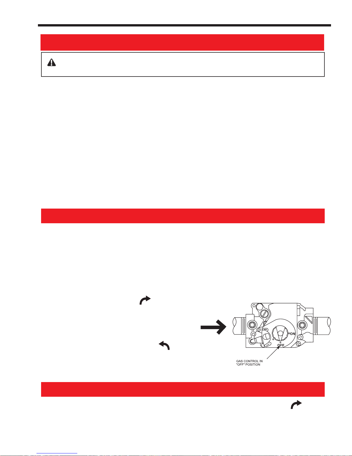
Model LJ Pool and Spa Heater
FOR YOUR SAFETY READ BEFORE OPERATING
WARNING: If you do not follow these instructions exactly, a fire or explosion may
result, causing property damage, personal injury or loss of life.
Page 25
A. This appliance does not have a pilot light. It is
equipped with an ignition device which
automatically light s the heater. Do NOT try to
light the burners by hand.
B. BEFORE OPERATING, smell all around the
appliance area for gas. Be sure to smell next
to the floor because some gas is heavier than
air and will settle on the floor.
WHA T TO DO IF YOU SMELL GAS
• Do not try to light any appliance.
• Do not touch any electric switch; do not use
any phone in your building.
• Immediately call your gas supplier from a
neighbor's phone. Follow the gas
supplier's instructions.
OPERATING INSTRUCTIONS
1. STOP! Read the safety information above on
this label.
2. Set the thermostat for "Pool" and "Spa" to 70°
F (21°C) and the controller mode to "OFF".
3. Turn off all electric power to the appliance.
4. This appliance is equipped with an ignition
device which automatically lights the heater.
Do not try to light the burners by hand.
5. Remove the heater door.
6. Turn gas control knob clockwise to "OFF".
7. Wait five (5) minutes to clear out any gas. Then
smell for gas, including near the floor. If you
smell gas, STOP! Follow "B" in the safety
information above on this label. If you don't
smell gas, go to next step.
8. Turn gas control knob counterclockwise to
"ON".
9. Replace control access panel.
• If you cannot reach your gas supplier, call
the fire department.
C. Use only your hand to push in or turn the
gas control knob. Never use tools. If the
knob will not push in or turn by hand, don't
try to repair it, call a qualified service
technician. Force or attempted repair may
result in a fire or explosion.
D. Do not use this appliance if any part has
been under water. Immediately call a
qualified service technician to inspect the
appliance and to replace any part of the
control system and any gas control which
has been under water.
10. Turn on all electric power to appliance.
1 1. Set thermostat to desired settings for "Pool"
and "Spa" and change the controller mode
from "OFF" to either "POOL" or "SP A".
12. If the appliance will not operate, check that
the filter pump is on, the filter is clean and
water is flowing to the pool. Otherwise, follow
the instructions "T o T urn Off Gas T o Appliance"
and call your service technician or gas
supplier.
DIRECTION OF
GAS FLOW
TO TURN OFF GAS TO APPLIANCE
1. Set the thermostat for "Pool" and "Spa" to
70°F(21°C) and the controller mode to "OFF"
2. Turn off all electric power to the appliance if
service is to be performed.
3. Turn gas control knob clockwise to
"OFF".
4. Replace control access panel.

Page 26
Table 6. LJ Controller Factory Default Settings
CONTROLLER
PARAMETERS
Real Time CLOCK Setting 1:00 (PM)
SPA Temperature Setting 10 2°F
POOL Temperature Setting 80°F
FREEZE Temperature S etting 38°F
Temperature Scale Setting
(°F/°C)
Pump Time Clock " ON"
(PROGRAM)
Pump Time Clock " OF F "
(PROGRAM)
Heater Status OFF
Pump Status ON
CONTROLLER DEFAULT
VALUES
°F
12:00 AM
11:59 PM
All values in the memory of the controller may be
reset to the default values at any time by depressing
and holding the 'ENTER' key for at least 7 seconds.
Default values are listed in Table 6.
Before starting your heater be sure to read and
become familiar with the Lighting and Shutdown
instructions in the previous section. Instructions are
also located on the inside of your heater.
7.4.1 Normal Operation
Be sure that the 'NORMAL' icon is displayed in
the upper left corner of the LJ controller display
screen. If it is not, depress the MODE key repeatedly
until the icon appears.
NORMAL
The heater is now in the normal operating mode.
Press the SELECT key repeatedly to toggle
between the 'POOL', 'SPA', and 'OFF' settings until
either the 'POOL' or 'SPA' icon appears above the
temperature reading.
POOL SPA
OR
If set to 'POOL', the pool temperature setting will
determine the temperature limit of the water. If set to
'SPA', the spa temperature setting will determine the
temperature limit of the water.
The heater is now set to come on when the pump
is running (between the programmed pump time clock
"ON" and "OFF" settings), and when there is a call for
heat (the inlet water temperature is more than 1° less
than the chosen temperature setting).
If these two conditions are met, the controller will
attempt to light the heater.
When the heater lights and the controller senses
flame at the burners, the 'FLAME' icon will appear on
the left side of the controller display above the temperature reading.
If the heater fails to ignite, it will attempt the
ignition two more times. If the heater fails to ignite
after the third try, the controller will lock out any
further attempts to light the heater. The controller will
show the service code 'FL 2' where the temperature
reading would normally be seen and the service icon
will appear in the center of the display (see
Section 9.2.1 "SERVICE CODES").
The controller also checks the power supply
voltage. If the voltage is insufficient to run the heater
properly (brown-out condition), the controller will
display the service code 'FL 5' and the service icon
(see Section 9.2.1 "SERVICE CODES").
When the controller is in the 'NORMAL' mode,
the heater will operate whenever the 'POOL '
or 'SPA' mode is chosen via the SELECT key,
the pump is on and there is a call for heat. Between
the programmed "ON" and "OFF" times set for the
pump time clock, the heater will operate automatically
if in the 'POOL' or 'SPA' mode. Outside of the
programmed "ON" and "OFF" times set for the pump
time clock, the pump must be turned on by pressing the
'PUMP' key. If not using the LJ controller pump time
clock, the external time clock must first be activated.
7.4.2 Pump Operation
The LJ controller allows two options for pump
control. It can allow operation of the pump by an
external time clock when it is set in the “External Time
Clock” mode (see Section 7.4.2.1). To operate in the
“External Time Clock” mode the controller must be
programmed with the factory default values indicated
in Table 6.
The LJ controller can also operate the pump in
the “Internal Time Clock” mode using it’s own internal
time clock to turn the pump on and off. This mode
requires the installation of the optional Jandy relay,
part number R0658100 (Refer to Figure 16 for wiring
diagram).
7.4.2.1 Pump Operation in “External
Time Clock” Mode
The heater is in the “External Time Clock” mode
when the controller's pump time clock is programmed
to turn on at 12:00 am and turn off at 11:59 pm. In this
mode, when ‘NORMAL’ is shown on the display, the
pump operation is controlled by the external time
clock. When in the "External Time Clock" mode, the
controller does not display the 'Real Time'. Instead,
three dashes (– – –) are displayed.
When using an external time clock to control the
filter pump operation, it is recommended that the time
clock have its own low voltage (Fireman’s) switch to
turn off the heater before turning off the pump. The
switch should shut off the heater at least 5 minutes
before the filter pump shuts off. This will allow for a
more efficient operation by removing any residual heat,
contained in the heat exchanger, back to the pool.

Model LJ Pool and Spa Heater
Page 27
When the controller is in the “External Time
Clock” mode, the PUMP key is disabled. Pressing the
PUMP key will temporarily show an “INVALID
COMMAND” message on the controller display.
7.4.2.2 Pump Operation in “Internal Time
Clock” Mode
To operate the pump using the internal time clock
of the controller, an optional pump relay, available
from your Jandy distributor, must first be installed (see
Section 6.4 "Pump Power Connection").
When the controller is in the “Internal Time
Clock” mode and “NORMAL” is shown on the
display, the pump will operate between the programmed "ON" and "OFF" times set for the pump time
clock on the LJ controller (see Section 7.2.5). The
display of the controller will show the time set for the
'Real Time Clock'. If power to the heater is lost at any
time, the controller will keep the last time or setting in
memory. When power is restored to the heater, all
settings will remain the same, but the real time display
will flash to indicate that a power loss has ocurred and
the time needs to be reset.
The pump can be turned off manually at any time
by pressing the PUMP key. If the heater is running
when the pump is turned off, the pump will go into
'COOL DOWN ' mode and continue to run for 5
minutes. If the heater was running within the last 5
minutes, the pump will continue to run for the time
remaining to complete a 5 minute cool down. The
'COOL DOWN' mode allows cool water to circulate
through the heat exchanger, removing residual heat
from the combustion chamber. When the pump is in
the 'COOL DOWN' mode, the controller will display
the 'COOL DOWN' icon just above the pump icon.
To turn the pump on at any time, press the
PUMP key. If the heater is in either the 'POOL' or
'SPA' mode, and the water temperature is less than
the pool or spa temperature setting the ignition sequence will begin.
7.4.3 Locking/Unlocking the Keypad
Once all of the limits have been set (see Section
7.2, "Setting the LJ Controller Functions and Limits")
you may choose to lock the keypad to prevent accidental changing of the limits set. Use the following
procedure to lock and unlock the keypad.
1. Press the MODE key repeatedly until the icon
'°F/°C' appears at the top of the display screen.
°F / °C
2. Press the ENTER key. The temperature scale
indicator in the lower right corner of the display
will start to flash.
°F
3. Press the MODE key one more time. The icon
'ULC' (unlocked) or 'LC' (locked) will flash on
the display where the real time clock usually
appears.
ULC
4. Press the UP or DOWN key to toggle between
'ULC' or 'LC'.
LC
5. Press the ENTER key to accept the choice and
return the controller to the NORMAL mode.
NORMAL
NOTE: Once the keypad is locked, any
attempted changes to the limits or functions of
the LJ controller will cause the LCD to
temporarily display an "Invalid Command"
message.
7.5. Remote Control Operation
7.5.1 Remote Control Connected At
Fireman Switch Terminal Block
To connect a remote control system, the LJ
controller must first be set up in the “External Time
Clock” mode. The heater is shipped from the factory
in this mode.
If the controller settings have been changed from
the factory settings, convert the controller to “External
Time Clock” mode by setting the 'PROGRAM' (pump
time clock) 'ON' and 'OFF' times to run for 24 hours.
To set the LJ controller into “External Time Clock”
mode, set the 'ON' time for the 'PUMP TIME
CLOCK' to 12:00 AM and the 'OFF' time to 11:59
PM. Refer to Section 7.2.5, "Setting the Pump Time
Clock". When the pump time clock is set with these
limits, it allows the internal time clock of the LJ
controller to run the pump for 24 hours. This setup
allows the heater to be controlled by the remote input
through the Fireman's Switch connection.
An interrupt (on/off) type remote switch can be
connected to the heater. To connect a remote ON/
OFF type switch to the heater, remove the wire nut
from the two red leads of the wire harness that
connects to the Fireman Switch connection on the
power circuit board (see Figure 19). Connect the wires
from the switch to the leads on the wire harness. This
type of remote control will turn the heater on or off,
but will not switch between pool and spa settings or
allow for temperature adjustments. These functions
are still controlled at the LJ controller on the heater.
The LJ heater also accommodates the use of a
more functional remote control. Remote controls that
provide their own temperature sensor such as the
Jandy AquaLink RS® remote control systems can be

Page 28
ON
OFF
ATTENTION
CONTROLLER
FLAME SENSOR
GAS VALVE
R
R
SAFETY CIRCUIT
FIREMAN
SWITCH
PUMP
BLOWER
POWER IN
SELECT
PLUG
IGNITER
POWER
POWER
IN
IN
Le manocontact de pression d’eau doit être
réglé de façon à ce que l’appareil cesse de
fonctionner si la pompe s’arrête. Si le
manocontact est réglé pour se fermer lorsque
le débit d’eau est trop faible, l’appareil risque de
s’endommager. Réglez le manocontact pour
qu’il arrête l’appareil, et non pour qu’il le mette
en marche.
Figure 19. ON/OFF Type remote switch
wired to the Fireman Switch connection. The LJ
controller must first be set up to recognize the remote
mode. The set up consists of setting the 'PROGRAM'
(pump time clock) 'ON' and 'OFF' times to run for 24
hours, setting the controller function to 'SPA' and
setting the spa temperature to 104°F (40°C).
To set the LJ controller for remote control use,
follow the instructions at the beginning of this section
setting the controller into the "External Time Clock"
mode.
To operate the heater by the remote unit, use the
SELECT key on the LJ controller keyboard to set
the heater to the 'SPA' mode.
Then follow the instructions in Section 7.2.3,
"Setting the Pool and Spa Temperatures", to set the
spa temperature limit to 104°F (40°C). This will allow
the remote system's temperature settings to control the
water temperature to a maximum of 104°F (40°C).
The LJ controller now acts as a "slave" controller
and heater functions are controlled by the remote
control system.
To restore control of the heater functions to the
LJ controller, disconnect the remote system from the
Fireman Switch, reprogram the pump time clock to
desired settings and reset the 'SPA' temperature to the
desired setting.
7.5.2 Remote Control Connected At The
Heater's Control Panel
The LJ heater control also provides the option of
using a remote switch to change the mode of the
heater. This remote will allow the user to change the
mode of the heater between 'POOL', 'SPA' and 'OFF'.
A more functional remote may be installed as stated in
the previous section.
A special Jandy wire harness is needed to install
the owner provided remote mode switch. Contact your
local Jandy distributor to order the wire harness kit
(Part Number R0398400). The wire harness kit
includes detailed instructions for the installation of the
wire harness and remote switch.
The pressure switch is preset at the factory for
activation at 2 psi (14 kPa). Adjust the pressure switch
only if any part of the filter system piping is 3 feet
(0.91 m) or more above the top of the heater jacket.
Do not adjust the pressure switch if the heater is
installed more than 15 feet (4.57 m) above or 6 feet
(1.83 m) below the pool surface. Consult your local
Jandy representative for recommendations.
On some installations, the piping from the heater
to the pool is very short. The back pressure could be
too low to trigger the pressure switch. If this happens,
it may be necessary to install a directional fitting or
elbows where the return line enters the pool. This will
increase back pressure enough for the heater to
operate properly.
Make sure the pool filter is clean before making
any pressure switch adjustment: A dirty filter will
restrict the water flow and the pressure switch cannot
be adjusted properly. To adjust the pressure switch:
1. Turn the pump 'OFF' by pressing the PUMP key
so that the display shows that the pump is 'OFF'.
If the heater was running it should go off immedi-
ately and the pump will run in the 'COOL
DOWN' mode for 5 minutes. If the heater has
been running within the last 5 minutes, the pump
will continue to run for the remainder of the 5
minute cool down period (see Figure 20).
2. Set the pool temperature control to the maximum
setting. Repeatedly depress the MODE key until
the indicator at the top of the display shows
'POOL SET'. Press the ENTER key. Then use
the UP key to set the temperature to 104°F
(40°C). Press the ENTER key again.
7.6 Water Pressure Switch Adjustment
CAUTION
The water pressure switch should be adjusted
to turn the heater off when the pump is off.
Setting the switch to close at too low of a flow
can damage the appliance. Adjust the switch to
turn the heater off, not on.
Figure 20. LJ controller display

Model LJ Pool and Spa Heater
Page 29
3. Turn filter pump on by depressing the PUMP
key. If a two-speed pump is used, make sure it
is at high speed.
NOTE: Heater should not be allowed to fire on
low speed.
4. Set the controller to 'POOL' by repeatedly
depressing the SELECT key until the display
shows that the heater is set to 'POOL'. The
heater should start.
5. Pry out the rubber dust plug on the top of the
pressure switch.
6. Use a 7/32 inch (5.55 mm) Allen wrench to turn
the adjustment screw very slowly clockwise
until the heater goes off (see Figure 21).
9. Return the pool temperature control to the desired
temperature. Repeatedly depress the MODE key
until the indicator at the top of the display shows
'POOL SET'. Press the ENTER key. Then use
the UP and DOWN keys to set the heater to the
desired temperature. Press the ENTER key again.
7.7 Temperature Rise
A temperature rise test confirms proper water
flow through the heater. The temperature rise is the
difference between the temperature of the pool or spa
water before and after heating, as measured in the
header. Perform the following temperature rise test
when the installation is complete:
1. Make sure the pool filter is clean.
2. Set the controller to 'OFF' by repeatedly depressing the SELECT key until the display shows that
the heater is 'OFF'.
3. If the filter pump is on, turn it off by pressing the
PUMP key and allow up to five minutes for the
pump to shut down.
Figure 21. Pressure Switch Adjustment
7. Slowly turn the pressure switch adjustment
screw counterclockwise one-quarter turn. The
heater should come back on.
8. Check the adjustment. Press the SELECT key
to turn the heater 'OFF'. Turn off the power to
the heater at the breaker. Unplug the pump
relay from the power circuit board. Restore
power to the heater. Press the SELECT key to
set the heater to 'POOL'. The heater must
not come on. If the heater does start the firing
sequence, immediately press the SELECT key
to turn the heater off; disconnect power to the
heater; plug the pump relay into the power
circuit board and restore the power to the
heater. Then repeat Steps 6 and 7. Check the
adjustment again. When the adjustment has
been checked and verified, press the SELECT
key to turn the heater off; disconnect power to
the heater; plug the pump relay into the power
circuit board and restore the power to the
heater.
4. Turn off the power supply to the heater at the
circuit breaker panel.
5. Remove the drain plug located on the inlet/outlet
header of the heater and replace it with a Pete's
plug (see Figure 15).
6. Insert a pocket thermometer (see Figure 15)
through the Pete's plug into the header.
7. Turn the circuit breaker on to supply the heater
with power.
8. Turn the filter pump on and wait 3 minutes. The
heater remains off. This allows water from the
pool to reach the heater.
9. Record the temperature indicated by the thermometer (cold water).
10. Set the pool temperature control to the maximum
setting. Repeatedly depress the MODE key until
the indicator at the top of the display shows
'POOL SET'. Press the ENTER key. Then use
the UP key to set the temperature to 104°F
(40°C). Press the ENTER key again.
11. Set the controller to 'POOL' by repeatedly
depressing the SELECT key until the display
shows that the heater is set to 'POOL'. The
heater should start.
12. Allow the heater to run for about 3 minutes.
Record the new temperature reading (heated
water).

Page 30
13. Subtract the first temperature reading (cold
water) from the second temperature reading
(heated water). The difference between the two
readings is the temperature rise. The temperature rise should be within the range shown in
Table 7.
Table 7. Temperature Rise and Minimum Flow Rates
Minimum Minimum Maximum
Size GPM (LPM) °F (°C) ° F (°C)
125 20 (76) 27 (15) 36 (20)
175 20 (76) 33 (19) 42 (24)
250 25 (95) 33 (19) 42 (24)
325 30 (114) 28 (16) 38 (21)
400 30 (114) 30 (17) 39 (22)
14. If the temperature rise is below the minimum
range indicated, two possibilities arise:
a. The supply gas volume is too low.
b. The system's water flow exceeds 125 GPM
(475 LPM), and requires a manual bypass
valve for proper operation. Install a manual
bypass (see Figure 7) and proceed
to Section 7.8.
15. If the temperature rise is above the maximum,
there is not enough water flowing through the
heater. Check for clogging in the water filter or
restriction in the water pipes.
c. Turn off the power to the filter pump at the
circuit breaker.
d. Remove thermometer and Pete's plug.
e. Replace the drain plug.
f. Turn on the power to the filter pump at the
circuit breaker.
g. Return the pool temperature control to the
desired temperature. Repeatedly depress the
MODE key until the indicator at the top of
the display shows 'POOL SET'. Press the
ENTER key. Then use the UP and DOWN
keys to set the heater to the desired
temperature. Press the ENTER key again.
7.8 Adjusting the Manual Bypass Valve
After the manual bypass valve is installed, use
the following procedures to adjust the bypass valve:
1. Make sure the pool filter is clean.
2. If the filter pump is on, turn it off by pressing the
PUMP key and allow up to five minutes for the
pump to shut down.
3. Turn off the power supply to the heater at the
circuit breaker panel.
4. Remove the drain plug located on the inlet/outlet
header of the heater and replace it with a Pete's
plug (see Figure 15).
CAUTION
Operating the heater with the temperature rise
above maximum or below the minimum can
damage the heater and may void the warranty.
ATTENTION
Opérer le chauffe-piscine au-dessus du niveau
de température maximale ou sous le niveau de
température minimale recommandée, peut
endommager le chauffe-piscine et ainsi annuler
la garantie.
16. If the temperature rise is within the correct
range, complete the procedure as follows:
a. Set the controller to 'OFF' by repeatedly
depressing the SELECT key until the
display shows that the heater is 'OFF'.
b. Turn the filter pump off by pressing the
PUMP key and allow up to five minutes for
the pump to shut down.
5. Insert a pocket thermometer (see Figure 15)
through the Pete's plug into the header.
6. Turn the circuit breaker on to supply the heater
with power.
7. Close manual bypass valve.
8. Set the controller to 'OFF' by repeatedly depressing the SELECT key until the display shows that
the heater is 'OFF'.
9. Repeat steps 8 through 13 of the temperature
rise test (see Section 7.7).
10. If the temperature rise is below the minimum
stated in Table 7, open the manual bypass valve
until temperature rise climbs between the min.
and max. range for your size heater. If the
minimum temperature rise stated in Table 7
cannot be reached with the manual bypass fully
open, then the gas supply volume is too low.

Model LJ Pool and Spa Heater
Page 31
11. If the temperature rise is above the maximum,
there is not enough water flowing through the
heater. Check for clogging in the water filter or
restriction in the water pipes.
12. Once the temperature is within the correct range,
safety wire the handle of the manual bypass
valve in place and tag the valve to prevent
change in the water flow.
13. Complete the procedure as follows:
a. Set the controller to 'OFF' by repeatedly
depressing the SELECT key until the display
shows that the heater is 'OFF'.
b. Turn the filter pump off by pressing the
PUMP key and allow up to five minutes for
the pump to shut down.
c. Turn off the power to the filter pump at the
circuit breaker.
d. Remove thermometer and Pete's plug.
e. Replace the drain plug.
f. Turn on the power to the filter pump at the
circuit breaker.
g. Return the pool temperature control to the
desired temperature. Repeatedly depress the
MODE key until the indicator at the top of the
display shows 'POOL SET'. Press the
ENTER key. Then use the UP and DOWN
keys to set the heater to the desired tempera-
ture. Press the ENTER key again.
SECTION 8.
Maintenance
8.1 Water Chemistry
Proper chemical balances are necessary for
sanitary bathing conditions as well as ensuring your
heater's long life. Be sure to keep your chemical levels
within the values indicated in Table 8.
Jandy Pool Products, Inc. does not warrant
heat exchangers damaged by corrosive chemical
levels or excess dissolved solids in pool or spa
water.
For spas, it is also necessary to perform water
changes in addition to chemical treatment. It is recommended to change the spa water every 60 days for
light usage and every 30 days if usage is heavy.
Table 8. Mineral Concentration Levels
Test Recommended Level
Free Chlorine or 1.0 to 3.0 ppm (3.0 to 5.0 spa)
Bromine 2.0 to 4.0 ppm (3.0 to 5.0 spa)
pH 7.4 to 7.6
Total Alkalinity (TA) 80 to 120 ppm
Calcium Hardness (CH) 200 to 400 ppm
Cyanuric Acid 30 to 50 ppm
Total Dissolved Solids (TDS) Less than 2000 ppm
Copper 0 ppm
* Concentration levels taken from “Basic Pool and Spa
Technology” published by NSPI (National Spa and Pool Institute).
8.2 Seasonal Care
CAUTION
Do not operate this heater outdoors at
temperatures below 20 degrees Fahrenheit (°F)
(-7 degrees Celsius [°C]).
ATTENTION
Ne faites pas fonctionner cet appareil à
l’extérieur à des températures inférieures à 20
degrés Fahrenheit (
[oC]).
8.2.1 Spring and Fall Operation
During periods when the pool is only going to be
used occasionally, set the pool and spa control temperatures to 70°F (21°C) (see Section 7.2.3). This
prevents the pool water from becoming chilled, and
minimizes the time required to raise the pool water
back up to the desired temperature.
In areas subject to only short freeze periods, turn
off the heater. The Freeze control function of the
heater will start the pump when the water temperature
falls to the 'FREEZE SET' temperature (see Section
7.2.4). (The freeze protection will only operate if the
internal relay is controlling the filter pump.) The pump
will run continuously until the water temperature has
risen to 2° above the 'FREEZE SET' temperature.
If the heater is not going to be used for a long
period of time, shut it down completely. Follow the
instructions found on the inside of the heater, or page
25 of this manual.
8.2.2 Winterizing
In areas where freezing temperatures occur in
winter, and the pool or spa will not be used, have your
o
F) (-7 degrés Celsius

Page 32
Figure 22. Heater drain locations
service technician perform the following steps:
1. Turn off the main gas supply valve to the heater,
outside the heater jacket.
2. Remove heater door.
3. Shut down the heater following the shutdown
instructions found on the inside of the heater.
4. Remove the drain plug from the return header
(see Figure 22), loosen the drain plug from the
inlet/outlet header, and completely drain the
heater before the first frost.
5. After all water has drained from the heater,
remove the drain plug from the inlet/outlet side.
Check for mineral buildup in the openings.
6. Use compressed air to blow out any standing
water remaining in the heat exchanger.
7. Grease the threads on the drain plugs and
reinstall plugs, but do not tighten.
8. Disconnect the pressure switch from the siphon
tube (copper tubing) (see Figure 23).
8.2.3 Spring Start-up
To restart the heater in the Spring, have a
professional service technician reassemble the heater
as follows:
1. Attach the copper tubing to the pressure switch
(see Figure 23).
Figure 23. Pressure switch copper tubing
while circulating.
4. Turn on the main gas supply valve to the heater,
outside the heater jacket.
5. Turn on the heater following the lighting instructions found on the inside of the heater, or page 25
of this manual.
8.3 Inspection and Service
Jandy Pool Products, Inc. designs and constructs
the Lite2 heater to provide long performance life when
installed and operated properly under normal conditions. Periodic inspections, especially at Spring startup, are important to keep your heater running safely
and efficiently through the years. Improper maintenance can result in conditions where nausea or
asphyxiation from carbon monoxide or flue gases could
cause severe injury, property damage or death.
2. Tighten the drain plugs.
3. Make sure that power is supplied to the heater
controller and the pump. Turn on the filter pump
by pressing the PUMP key and circulate water
through the heater for 5 minutes. Check for leaks
WARNING
Improper installation or maintenance can cause
nausea or asphyxiation from carbon monoxide
in flue gases which could result in severe injury,
or death.

Model LJ Pool and Spa Heater
Page 33
AVERTISSEMENT
Une installation ou un entretien inadéquat peut
causer la nausée ou l’asphyxie en raison du
monoxyde de carbone présent dans les gaz de
combustion et même entraîner des blessures
graves ou la mort.
8.3.1 Owner Inspection
Jandy Pool Products, Inc. recommends that you
inspect the heater on a continual basis and especially
after abnormal weather conditions. The following basic
guidelines are suggested for your inspection:
1. Keep the top and surrounding area of the heater
clear of all debris.
2. Keep the area around and beneath the heater
clean and free of all combustible materials such
as paper, leaves, etc.
3. Do not store or use gasoline or other flammable
vapors, liquids or chemicals in the vicinity of this
or any other appliance.
Ne pas entreposer ni utiliser d'essence ni d'autres
vapeurs ou liquides inflammables à proximité de
cet appareil ou de tout autre appareil.
4. Do not use the heater if any part has been under
water. Immediately call a qualified professional
technician to inspect the heater and replace any
part of the control system which has been
submerged.
8.3.2 Professional Inspection
Inspections performed at least once a year by a
qualified technician are required to maintain your
heater's safe and efficient operation. The following
basic safety checks must be performed.
1. Inspect the venting system for blockage, leakage,
and corrosion.
2. Check for spider webs in or other obstructions in
the main burner orifices – especially at Spring
start-up. Clean with wire brush if necessary.
3. Check for loose or broken wires and terminal
connections.
4. Inspect the electrical controls, specifically the
following:
a. High limit controls.
b. Water pressure switch.
c. Temperature control.
d. Ignition control.
e. Automatic gas valve.
f. Fusible link.
g. Igniter fuses.
h. Control circuit fuse (Power Board).
i. Power distribution board.
5. Inspect the external surfaces of the heat ex-
changer tubes for black carbon soot buildup by
placing a mirror between and under the burners
when the heater is firing. Remove any soot that
has collected on the tubes, and correct the cause.
N'utilisez pas cet appareil s'il a été plongé dans
l'eau, même partiellement. Faites inspecter
l'appareil par un technicien qualifié et remplacez
toute partie du système de contrôle et toute
commande qui ont été plongés dans l'eau.
5. If the heater is equipped with a pressure relief
valve, check for corrosion in and around the
valve. Twice a year, with the filter pump on, lift
the release lever on the top of the valve to make
sure that water runs freely through it. If corrosion is found, replace the pressure relief valve.
When replacing the valve, be sure that the pump
is off. Install the valve so that the discharge is
directed away from any area that may be
damaged by water.
6. Be sure all combustion air and ventilation openings are not blocked. Check for spider webs and
other debris inside the heater, in the vents on all
sides of the heater jacket and in the exhaust
outlet– especially after a long period of nonuse.
NOTE: After installation and first start-up,
check the heat exchanger for black carbon soot
buildup after the following periods of operation:
24 hours, 7 days, 30 days, 90 days, and once
every 6 months thereafter.
6. If the heater is equipped with a pressure relief
valve, check for corrosion in and around the
valve. With the filter pump on, lift the release
lever on the top of the valve to make sure that
water runs freely through it. If corrosion is found,
replace the pressure relief valve. When replacing
the valve, be sure that the pump is off. Install the
valve so that the discharge is directed away from
any area that may be damaged by water.
7. Verify pressure switch operation. Press the
SELECT key to turn the heater 'OFF'. Turn off
the power to the heater at the breaker. Unplug
the pump relay from the power circuit board.
Restore power to the heater. Press the SELECT
key to set the heater to 'POOL'. The heater
must not come on. If the heater does start the
firing sequence, immediately press the SELECT

Page 34
key to turn the heater off, disconnect power to
the heater, plug the pump relay into the power
circuit board and restore the power to the heater.
Refer to Section 7.6 "Adjusting the Pressure
Switch" for procedures on adjusting the pressure
switch. When the adjustment has been checked
and verified, press the SELECT key to turn the
heater off, disconnect power to the heater, plug
the pump relay into the power circuit board and
restore the power to the heater.
NOTE: Keep this manual in a safe place for
future reference by you and your professional
technician when inspecting and servicing the
heater.
SECTION 9.
Troubleshooting
8. Conduct a normal operating cycle and observe
that the sequence proceeds as intended.
Caution
For your safety, when starting the heater, keep
your head and face away from the lower firebox
opening to prevent any risk of personal injury.
ATTENTION
Pour votre sécurité personnelle, lorsque vous
mettez l’appareil en marche, tenez votre tête et
votre visage loin du brûleur pour éviter tout
risque de blessure.
9. Make a visual check of the main burner flame.
The flame can be seen in a mirror arrangement
held beneath the burners. The flame should be:
a. Blue in color.
b. 1 to 4 inches (25mm to 102mm) above
burner surface (see Figure 24).
9.1 General Heater Troubleshooting
The table on the following page lists some of the
more common problems, causes and solutions encountered when running the heater. Most problems occur
when the heater is being started for the first time after
installation or at Spring start-up. Careful installation
and maintenance will help ensure years of trouble free
use from your Lite2 pool heater.
9.2 LJ Controller Service Codes
9.2.1 Explanation of Service Codes
The LJ controller monitors several functions of
the heater. In the event of a malfunction, the controller
will display a service code where the inlet temperature is usually displayed and a service icon in the
middle of the display. See Figure 25 for appearance
and location of typical service code display.
Figure 24. Main Burner Flame
10. Perform a temperature rise test in accordance
with Section 7.7.
11. Return the pool temperature control to the
desired temperature. Repeatedly depress the
MODE key until the indicator at the top of the
display shows 'POOL SET'. Then use the UP
and DOWN keys to set the heater to the desired
temperature.
Figure 25. Typical Service Code Display
The service codes are listed on the following
pages.
Only three of these service codes are reconcilable without the services of a qualified technician. The
first is the case where the heater does not start after
the first three attempts, FL2. This may occur after a
prolonged period of nonuse of the heater, especially at
Spring start-up. However, the repeated appearance of
this error requires the service of a qualified technician.
The second case is that of a temporary brownout condition, FL5. If the brown-out is regional, then
the controller will automatically reset when full power
is restored by the electric company. However, if the
brown-out is due to a low voltage supply problem only
on the heater circuit, then immediately shut off the
electrical supply to the heater and call a certified
electrician.
The last case is the filter is dirty condition, FL0.

Model LJ Pool and Spa Heater
Page 35
Troubleshooting Table
# Symptom Cause Remedy
1. Pump not A.No power A.Check circuit breakers and power source.
operating B.Pump defective B.Replace.
2. Flame roll-out A.Blocked flue A.Remove blockage.
on start-up B. Igniter out of position (delayed ignition) B.Correct igniter position.
3. Spillage at A . Cold chimney A . Allow heater to operate 5 minutes to create draft action.
draft hood B. Vent pipe pitches down to chimney B.Reinstall vent pipe to pitch up from heater to chimney.
4. Flame has A . Low primary air A . Correct manifold pressure according to rating plate. Correct
lazy yellow tip orifice size if necessary (see parts list). Clean burner ports if
5. Not enough heat A.Inadequate gas supply A.Gas meter too small. Gas line from meter to heater too small.
6. Heater pounding A. Water flow through heater too low A . Check temperature rise between inlet and outlet heater
or knocking piping. See Section 7.7 for recommended range of
7. Heater condensing A. Low water temperature A. Flue product moisture will condense at the start-up until the
8. Igniter lights but A . Gas valve not at “on” position A .Turn knob to “on” position.
main burners B. Air in gas line B. Cycle ignition sequence until air is out of the gas line.
will not come on C. Gas valve failed C.Replace gas valve.
C. Incorrectly wired C. Recheck wiring including relay if using LJ controller internal
clock.
D. Pump relay defective D. Replace pump relay.
E. Current time not within E. Set time clock and current time.
time clock settings
F. Controller defective F. Replace controller.
C. Blocked heat exchanger C. Clean and correct as necessary.
D. Refractory blanket out of place D. Correct or replace blanket as necessary.
E. Altered draft hood E. Install factory-provided draft hood.
F. Downdraft conditions F. Install draft hood.
C.Blocked chimney C.Remove blockage.
D. Draft hood altered D. Install factory-provided draft hood.
E. Prefabricated chimney with incorrect cap E. Install a Nationally Recognized Testing Lab (NRTL) listed vent
cap.
dirty.
B. Low manifold gas pressure B.Gas pressure on heater manifold should be adjusted to
4.0"W.C. for natural gas, 9.0"W.C. for propane.
C. Heater size inadequate C. Replace with heater of higher input.
temperature rise. If temperature rise is above the maximum
recommended, increase pipe size or pump capacity or
locate obstruction. Check for closed valve in system.
heater water temperature reaches the normal operating
conditions.
B. Heater plumbed backwards B. Correct plumbing.
To clear the FL2 service code, turn off the
heater by using the SELECT key to turn the heater to
the 'OFF' position and then turn it back to either
'POOL' or 'SPA'. The heater will now go back to the
normal operating mode. If there is a call for heat the
heater will attempt ignition again. If the ignition fails
again, contact a qualified technician to check the
heater.
All other service codes will need the attention of
a qualified technician to resolve the problem.
9.2.2 Resetting LJ Controller Service
Codes
The LJ controller will display service codes to
help in identifying fault conditions that effect the
operation of the heater (see Section 9.2.1).
There are four service codes that will reset
automatically once the fault condition has been resolved.
Service code FL0, "open switch in the safety
circuit", will reset after the open switch has been reset
or replaced. The display will show the normal operating icons.
NOTE: If the pump is turned off while the
heater is running, service code FL0 will be
displayed because the water pressure switch
will detect the drop in water pressure and open
the safety circuit. When the pump is restarted,
the water pressure switch will close and the
heater will resume normal operation.
Service code FL1, "temperature sensor shorted",
will reset after the short has been repaired, or a new
sensor installed. The display will show the normal
operating icons.

Page 36
LITE2 LJ CONTROLLER HEATER SERVICE DIAGNOSTIC GUIDE
SERVICE CODE CAUSE REMEDY
FL 0
(open switch in the
safety circuit)
FL 1
(temperature sensor)
1. Pressure Switch Opened
A. Pump is not running.
B. Low pump/water pressure.
C. Air is in the water line.
D. Pressure switch fault.
2. Hi Limit Switch Tripped
A. Water temperature in heater
exceeds the internal limit.
B. Limit switch fault.
3. Fusible Link Opened
A. Internal cabinet temperatures
exceed the fusible link limit.
B. Fusible link fault.
1. Temperature Sensor Error
A. Temperature sensor opened or
shorted.
B. Failed sensor.
A. Turn pump on or check to see that external time
clock is synchronized with LJ controller time
clock.
B. Clean filter or clear blockage/check position of
valves in plumbing system.
C. Check for air leaks in plumbing system.
D. Adjust or replace pressure switch. Refer to
qualified personnel.
A. Identify and correct cause of overheating. Refer
to qualified personnel.
B. Identify and correct loose connections or replace
switches. Refer to qualified personnel.
A. Identify and correct cause of overheating. Refer
to qualified personnel.
B. Identify and correct loose connections or replace
fusible link. Refer to qualified personnel.
A. Check for loose connections and inspect sensor
wires and routing.
B. Replace temperature sensor. Refer to qualified
personnel.
FL 2
(failed ignition)
1. No Ignition
A. Low gas supply pressure.
B. Air in gas line.
C. No gas flowing.
D. Gas valve fault.
2. Ignition, but no Flame Sensing
Capabilities
A. Flame sensor is not in the
flame.
B. Flame sensor circuit is open.
C. Flame sensor rod is grounded.
D. Flame sensor circuit is
shorted.
A. Identify and repair incorrect supply pipe size or
pipeline blockage. Refer to qualified
personnel.
B. Shutdown heater and restart. If the heater does
not ignite, refer to qualified personnel.
C. Be sure that the manual gas cock and the
automatic valve are in the "ON" position. Check
for loose wire connections at gas valve.
D. Replace gas valve. Refer to qualified
personnel.
A. Ensure that the flame sensor is aligned over the
burner. Refer to qualified personnel.
B. Identify and correct loose connections. Refer to
qualified personnel.
C. Ensure that flame sensor is installed properly
and is not in contact with burner or heater jacket.
Refer to qualified personnel.
D. Inspect flame sensor rod, wiring and connections
between sensor and power circuit board. Refer
to qualified personnel.

Model LJ Pool and Spa Heater
SERVICE CODE CAUSE REMEDY
FL 2 (cont'd)
(failed ignition)
E. Flame sensor circuitry is not
well grounded.
F. Low gas supply pressure.
G. Heater is wired incorrectly.
H. Failed sensor.
3. Rapidly Cycling Pressure
Switch
A. Air leak in water line or pump.
B. Insufficient back-pressure to
heater.
E. Ensure that the green wire from
the 6-pin connector to the power circuit board is
tightly attached to the ground screw with a star
washer.
F. Identify and repair incorrect supply pipe size or
pipeline blockage. Refer to qualified
personnel.
G. Ensure proper wiring. See wiring diagram in
manual or on door of heater for details. Refer to
qualified personnel.
H. Replace flame sensor.
A. Locate and repair leak.
B. Install restrictive fitting at pool/spa outlet. Refer
to qualified personnel.
Page 37
FL 3
(flame detected when
no flame should
exist)
FL 4
(igniter)
FL 5
(brown-out)
FL 6
(24V signal to gas
valve)
1. Flame Sensor Error
A. Flame exists prior to ignition
sequence.
B. Failed controller.
1. Igniter Failure
A. Igniter circuit is open.
B. Element has a fine crack in it.
C. Igniter fault.
1. Brown-out Condition
A. Incoming voltage is too low to
safely operate heater.
B. Heater supply voltage is 115V
but power conversion plug is
plugged in on 230V side.
1. Power Module Failure
A. 24V signal is not being sent to
energize the gas valve.
A. Carefully inspect heater for signs of fire damage.
Refer to qualified personnel.
B. Replace controller. Refer to qualified
personnel.
A. Check fuses on igniter wires. Identify and correct
loose connections or broken wires. Refer to
qualified personnel.
B. Measure room temperature resistance and
ensure value is in the correct range. See manual
for details. Refer to qualified personnel.
C. Replace igniter. Refer to qualified personnel.
A. No Service Required. Heater will automatically
reset itself once proper voltage is restored. If
error persists, Refer to qualified personnel.
B. Reverse power conversion plug.
A. Replace power module board. Refer to
qualified personnel.
FL 7
(remote operation
circuit)
1. Remote Operation Circuit
A. Remote control switch circuit is
open. (Controller is not in
remote control mode).
B. Remote control switch circuit is
not open.
A. Identify and correct loose connections. Refer to
qualified personnel.
B. Replace power module board. Refer to
qualified personnel.

Page 38
Service code FL3, "flame detected when no
flame should exist", will reset after the problem has
been resolved.
Service code FL5, "brown-out condition exists",
will also reset after the condition has been resolved.
However, the reset may take up to 3 minutes. The LJ
controller checks the power supply voltage every 3
minutes. If the supply voltage drops below 85% of the
nominal supply voltage, the display will show the FL5
service code and the heater will not start the ignition
sequence. The controller will check the supply voltage
again 3 minutes later. If the low voltage condition still
exists the FL5 service code will remain. If the actual
supply voltage is above 85% of the nominal supply
voltage, the service code will clear automatically from
the display and the heater will resume normal operation. If the heater was in either 'POOL' or 'SPA' mode
when the brown-out condition was detected, it will
remain in that mode when the condition is resolved. If
the water temperature is less than the thermostat
setting, the ignition sequence will start automatically
and the heater will operate normally.
Once any other service code has been displayed,
it will need to be reset after the fault condition has
been resolved. Once the problem has been identified
and repaired, press the SELECT key
repeatedly to turn the heater off . Then
press the SELECT key again to set the controller to
either 'POOL' or 'SPA'. The controller should send the
heater through the ignition sequence and the heater
will operate normally.
SECTION 10.
Professional Maintenance and
Service
WARNING
SERVICING SAFETY
Some of the servicing procedures for the Lite2
model LJ pool heater are hazardous because
they involve fuel gas, electricity, moving parts
and procedures which require testing or
temporary bypass of safety controls. For this
reason, the heater must be serviced only by a
qualified professional service technician.
AVERTISSEMENT
PRÉCAUTIONS LORS DES RÉPARATIONS
ET DE L’ENTRETIEN
Certaines procédures d’entretien et de
réparation des appareils de chauffage à LJ
présentent des dangers, car elles mettent en
jeu des gaz combustibles, des composants
électriques, des pièces mobiles et des
procédures qui nécessitent des mises à l’essai
ou la dérivation temporaire des commandes de
sécurité. Pour cette raison, l’appareil de
chauffage doit être entretenu et réparé
uniquement par un technicien professionnel
qualifié.
DANGERS D’UN ENTRETIEN INADÉQUAT
Les appareils de chauffage à LJ comportent
des caractéristiques techniques uniques. Une
réparation ou un entretien inadéquat peut
entraîner des blessures corporelles ou des
dommages à la propriété. Pour cette raison,
l’appareil de chauffage doit être entretenu et
réparé uniquement par un technicien
professionnel qualifié.
10.1 General Information
A qualified professional technician must service
the Lite2 model LJ pool heater using Jandy Pool
Products, Inc. service procedures. Before calling for
service, however, the owner should check for obvious
problems. The other components in the pool system,
including pump, filters and strainers, water valves, gas
supply, electrical power and time clocks, have an
effect on heater operation.
Confirm that the LJ heater control is set to
'POOL' or 'SPA' and that the corresponding temperature limit is set high enough to make the heater operate. Make sure the pump is operating, that the filter is
clean and strainers are not clogged, that there are no
mis-positioned water valves, that the gas or electric
power supplies are not shut off and that time clocks
are properly adjusted. Also be sure that there is no
blockage of the vent or louvers which supply combustion air to the burners.
IMPROPER SERVICE HAZARD
The Lite2 model LJ pool heater incorporates
unique design features. Incorrect service of this
heater can result in personal injury or damage
to property. To avoid such hazards, the heater
must be serviced only by a qualified
professional service technician.
10.2 Natural-Draft Combustion System
The Lite2 model LJ pool heater has an atmospheric combustion system. This system is illustrated in
Figure 26.
As the heated exhaust gases rise out of the
combustion chamber, flow is created through the
system and fresh combustion air is drawn into the
heater through the louvers cut into the front and sides
of the heater. Gas is forced through an orifice into the

Model LJ Pool and Spa Heater
Page 39
EXHAUST
VENT TOP
FLUE COLLECTOR
HEAT EXCHANGER
COMBUSTION CHAMBER
BURNER
AIR
FLOW
Figure 26. Atmospheric Combustion System
open end of a burner. When the gas flows into the
burner, a “negative” pressure is created at the opening
of the burner. This negative pressure pulls air into the
burner with the gas and mixes the two together. As
the gas/air mixture flow through the burner ports it is
ignited in the combustion chamber. Hot combustion
products then raise through a highly efficient heat
exchanger. Combustion products then enter a flue
collector and are directed to the outdoors through the
grate top of the heater or a vent pipe and cap.
10.3 Heater Components and Their
Operation
1. Gas valve / Regulator - The gas valve controls
gas flow into the manifold. It provides flow only
when the temperature controls require heat and
only if all safety controls enable operation. It is
also a positive pressure regulator. It regulates
the gas pressure in the manifold to specifications
addressed earlier in this manual. This is necessary for proper operation of the burner system.
2. LJ Temperature Control/Ignition Control
Combination Systema. Temperature Control-The Jandy LJ
controller is an electronic control which senses
water temperature by means of a thermistor and
controls heater operation to bring the water to the
temperature selected. It has an option for two
separate thermostat settings which are typically
BURNER TRAY SHELF
used to set pool and spa temperatures. A pushbutton selector key is used to switch between
settings.
b. Ignition Control - The ignition control is
integrated with the temperature control. It
provides energy for ignition of the air/gas mixture, monitors the flame and controls the gas
valve. When the temperature control requires
heat, the ignition control provides a pre-purge of
the combustion chamber. Then it applies electrical power to a “hot surface” igniter. When the
igniter is hot enough, the ignition control opens
the gas valve. It has sophisticated means to
sense ignition and flame condition so that unburned gas will not escape. After the burner is
shut off, the ignition control continues operation
to provide a post-purge period.
3. Igniter - The hot surface igniter is a ceramic
composite element which becomes very hot
when electrical power is applied to it. The hot
surface igniter directly ignites the air/gas mixture
in the combustion chamber.
4. Flame Sensor - The flame sensor is the elec-
trode through which the ignition control detects
“rectification” of current passed through the
flame. Inadequate rectification indicates an
unsatisfactory flame condition. The ignition
control responds to the flame signal provided by
the flame sensor.

Page 40
CIRCUIT TEST POINTS
POWER DISTRIBUTION BOARD TEST POINTS
9
8
7
6
5
4
2
3
1
Figure 27. Power and Control Circuit Test Points
1110

Model LJ Pool and Spa Heater
Page 41
5. Limit Switches - Two limit switches prevent
excessive water temperature - one within the
heat exchanger and one for water leaving the
heater. If either senses excessive temperature,
burner operation is interrupted.
6. Water Pressure Switch - This control senses
whether or not water is available to the heater by
measuring back pressure inside of the heat
exchanger. If the pool water pump fails or the
water filter is blocked, the pressure switch
prevents operation of the burner.
7. Fusible Link - This is a single-use switch which
detects abnormal temperature in the component
vestibule. It is a fusible link which is held to the
inner panel just above the burner tray by a sheet
metal bracket. Excessive temperature in the
component compartment, possibly due to a
blocked flue or flame roll-out, will cause the link
to fail. This opens the safety circuit which shuts
off the gas valve and shuts the heater down.
10.4 Electrical Troubleshooting
This section describes procedures for checking
the electrical power and control components of the
heater one at a time and in the order they appear in the
control circuit.
Note: Pump must be running during the
troubleshooting procedure.
These procedures require a Volt-Ohm meter
with a minimum 0-250 VAC voltage range, and 0-1000
Ohm resistance range. Figure 27 shows the power and
control circuits, and where to take measurements.
Location numbers and letters in circles have been
added, and will be referenced in the following sections.
As stated at the beginning of this manual, some
of these procedures are hazardous. Only a qualified
service technician should service the heater.
10.4.1 Electrical Power Supply
The electrical components of the Lite2 pool
heater are designed to operate with supply voltage
ranging from 98V to 126V at 60 Hz if connected to a
nominal 115 volt power supply or 196V to 253V at 60
Hz if connected to a nominal 230 volt power supply.
Measure supply voltage at the “hot” and “neutral”
screw terminals in the heater electrical junction box
(identified as points A and B on the wiring diagram). If
no voltage is present, correct this external power
supply problem to the heater. Circuit breakers, time
clock settings or similar devices may be the problem.
Voltage outside of the above ranges may be due to
poor wiring, poor connections, other loads such as air
conditioning compressors or to an electric utility
company problem. Arrange for correction of the
voltage as appropriate.
10.4.2 Controller
The controller must be operational in order to
check the control circuits of the heater. If the red LED
on the power distribution board is on but the controller
does not show a display, then it is defective. Replace
the controller. If the LED is not on, then check the
control circuits as outlined in the following sections.
10.4.3 Control Circuit Troubleshooting
The heater controls and sensors are powered by
three major circuits on a power distribution board (PC
board). 115 VAC or 230VAC is brought to the power
distribution board by the heater supply voltage. The
voltage is then transmitted through the board and the
power conversion plug to the igniter and to a transformer. When 115V is supplied to the heater, the
power conversion plug passes the signal unchanged to
the igniter and configures the input to the transformer
for 115V. When 230V is supplied to the heater, the
power conversion plug modifies the voltage to 115V
before sending it on to the igniter and configures the
input to the transformer for 230V. It is important to be
sure that the correct side of the power conversion plug
is plugged into the power distribution board. The
transformer converts the 115 volt AC or 230 volt AC
supply into two separate outputs, 24 volts AC and 12
volts AC. These voltages are supplied back to the
power distribution board where the 24 volt signal is
used to power the fireman switch, safety circuit and
gas valve, while the 12 volt signal is used to power the
keypad controller. Troubleshooting is done by probing
for voltage at various points on the power distribution
board, and heater components to determine which
component is preventing operation. Check points are
indicated on Figure 27. The recommended procedure
steps through each circuit in a sequential way, and
each section assumes that components from all
previous sections have been tested and are operational. However, verifying voltage at any of the
numbered points in that circuit confirms that all prior
components of the circuit are operational. Experienced
technicians may be able to shorten the process by
going directly to one of the intermediate major test
points. For example, if 24 volts is measured at test
point 8, then all components in the circuit prior to test
point 8 (fireman switch and entire safety circuit) are
operational.
10.4.3.1 Transformer
To check the 24 volt transformer output, attach
the black lead of the voltmeter to the transformer
connector where the blue wire enters near the center
of the connector (test point 1 on Figure 27). You will
need to push the voltmeter lead into the back of the
connector along side of the wire pin. Touch the free
lead of the meter to the transformer connector where
the second blue wire is attached at the end of the
connector (test point 2). The meter should show 20-28

Page 42
volts. If there is no voltage, replace the transformer.
To test the 12 volt transformer output, leave the black
lead of the meter at test point 1 and touch the free
lead of the meter to the transformer connector where
the white wire is attached (test point 3). The meter
should show 10-14 volts. If there is no voltage, replace
the transformer.
10.4.3.2 Fuse
Leaving the black voltmeter lead in place at test
point 1, touch the free lead to the end of the fuse (test
point 4). The meter should read 20-28 volts. If there is
no voltage, the fuse has failed. Inspect the rest of the
wiring, especially the safety circuit, to be sure that
there is no “short” such as contact of a terminal with
the heater chassis or another terminal which may have
caused the fuse to fail. Correct any such condition and
replace the fuse.
10.4.3.3 Fireman Switch and External
Interlocks
Check the voltage going to the external device.
Move the black voltmeter lead to test point 2. (This
lead can be left in place for most of the testing.)
Touch the free lead of the meter to the fireman switch
connector where the red wire is attached at the lower
end of the connector (test point 5). The meter should
read 20-28 volts. If there is no voltage, there may be a
bad connection on the power distribution board and the
board may need to be replaced. If voltage is detected
at test point 5, move the free lead of the meter to the
fireman switch connector where the other red wire is
attached at the upper end of the connector (test point
6). The meter should read 20-28 volts. If there is no
voltage, the time clock switch or other external
interlock may be mis-adjusted, mis-connected or
defective. Correct this external problem.
10.4.3.4 Fusible Link
Check the voltage going to the safety circuit.
Leave the black voltmeter lead in place at test point 2.
Touch the free lead of the meter to the safety circuit
of the six pin connector where the red wire is attached
at the lower left corner of the connector (test point 7).
The meter should read 20-28 volts. If there is no
voltage, there may be a bad connection on the power
distribution board and the board may need to be
replaced. If voltage is detected at test point 7, move
the free lead of the meter to the terminal of the fusible
link where the white wire is connected (test point C).
If no voltage is detected at test point C, the
fusible link has failed. This indicates higher than
normal temperatures in the component compartment
(vestibule). Normal component compartment temperature is well below 300
o
F. The fusible link is designed to
fail at temperatures above 305°F. Excessive temperature might be due to a blocked flue or heat exchanger.
Clean the heat exchanger and clear the flue and vent
of any restrictions. Sometimes the fusible link fails due
to flame roll-out. Flame roll-out may be caused by
delayed ignition or downdrafting in windy areas.
Thoroughly investigate the causes for flame roll-out
and correct the problem when replacing the fusible
link.
10.4.3.5 Limit Switches
Since the limit switches are not easily accessible,
you can check the voltage going into the component
after the limit switches in the circuit. If voltage is
detected there, then the limit switches are closed and
are operational.
Check the voltage going to the water pressure
switch. Leave the black voltmeter lead in place at test
point 2. Touch the free lead of the meter to the
terminal of the water pressure switch where the white
wire is connected (test point D).
If there is no voltage, one of the limit switches is
open. This is normally due to excessive water temperature, which should be thoroughly investigated
before replacement of limit switches. Excessive water
temperature may be caused by low water flow. Water
flow deficiency may be due to obvious problems such
as a defective pump or blocked water filter. Alternatively, excessive water temperature may be due to
over-firing, or to a problem with the water piping or
the heater's internal bypass control. Over-firing might
be a result of an incorrect gas orifice or supply of
propane gas to a heater intended for natural gas. If
there are no such fundamental problems, identify
which of the switch is open by temporarily connecting
a jumper wire across its terminals. Replace a defective
limit switch. Limit switch access is through the limit
switch cover on the side of the heater to which water
pipes are connected.
Note that the limit switches have different trip
points, and it is important that replacements are
correct. The 150°F switch has a red dot on the top of
the brass fitting, and must be installed in the lower
(horizontal) well in the header. The 135°F switch has
no dot and must be installed in the upper (vertical) well
in the header.
10.4.3.6 Water Pressure Switch
If voltage is detected at test point D, move the
free lead of the meter to the terminal of the water
pressure switch where the white wire is connected
(test point E).
If there is no voltage, the pressure switch contacts
are open. This is almost always due to a water flow
deficiency, the most common one being a blocked water
filter or defective pump. However, sometimes it is due
to blockage of the copper siphon loop tube or misadjustment of the switch. Investigate thoroughly,
referring to Section 7.6 on “Adjusting the Pressure

Model LJ Pool and Spa Heater
Page 43
Switch”. If there is no problem with the pool system or
pressure switch adjustment, replace the pressure
switch.
If test point E shows 24V, move the free lead of
the meter to the safety circuit of the six pin connector
where the black wire is attached at the lower right
corner of the connector (test point 8). If there is no
voltage at test point 8, then the connection from the
pressure switch to the power distribution board is bad.
Replace the six pin connector.
10.4.3.7 Gas Valve Voltage
Check the voltage going to the gas valve. Leave
the black voltmeter lead in place at test point 2. Touch
the free lead of the meter to the gas valve terminal
where the brown wire is attached at the center
position of the right side of the connector (test point 9).
This test point will have voltage present only during a
trial for ignition or during normal operation. The meter
should read 20-28 volts. If there is no voltage, there
may be a bad connection on the power distribution
board and the board may need to be replaced.
Listen closely to the gas valve when it is first
energized (24V first appears at test point 9 during the
trial for ignition). There should an audible "click" when
the valve opens.
If there is voltage at test point 9, but the gas
valve does not open, replace the valve.
WARNING
The igniter and some terminals of the power
distribution board utilize 115V or 230V power
and require appropriate servicing precautions.
Note that wires and terminals of these
components may be “hot” or "live" even when
the component is not operating.
AVERTISSEMENT
Le dispositif d’allumage, le circuit d’alimentation
électrique et certaines bornes de la commande
d’allumage utilisent une tension de 115 V ou de
230 V et exigent des précautions appropriées
lors du service d’entretien et de réparation.
Notez que les fils et les bornes de ces
composants peuvent être sous tension
même si le composant ne fonctionne pas.
reading can be obtained by using an RMS voltmeter if
one is available. When using an RMS voltmeter, a
reading of 98-126VAC is expected. This voltage will
be applied only when there is an attempt to ignite the
burner or when the ignition control’s flame sensing
system has determined that it is OK to allow burner
operation. Even if voltage has been confirmed at the
end of the safety circuit, the “trial for ignition” sequence is imposed by the ignition control. This sequence consists of a 15 second period of pre-purge, a
10 second period for heat-up of the igniter and a 12
second trial for ignition. During this last 22 seconds
there is voltage between test point 10 and test point
11. If satisfactory ignition is not achieved, the igniter is
turned off and the system waits for a 45 second postpurge period. The system may go through this cycle as
many as three times, but thereafter it is “locked out”
by the ignition control. Additional attempts will be
made only if the call for heat is interrupted by turning
off electrical power or setting the LJ controller to
'OFF' and then back to 'POOL' or 'SPA'.
To troubleshoot the ignition control, connect the
voltmeter leads at test points 10 and 11, and set the LJ
controller to call for heat. Observe that the normal
ignition sequence takes place. After the 15 second
prepurge, note the voltage between test points 10 and
11. Then look for the glow of the igniter by placing a
mirror on the bottom of the burner tray. If voltage does
not appear between points 10 and 11 during the trial
for ignition, replace the power distribution board.
If the correct voltage is detected between points
10 and 11 during the trial for ignition but the igniter
does not glow, check the connections to the igniter.
Disconnect the igniter wires from the in-line fuse
harnesses and the fuse harnesses from the power
distribution board. Using an ohmmeter, check each
fuse and harness for continuity. If the ohmmeter reads
an open circuit, the fuse has failed. The fuses are in
place to protect the power distribution board in the
event of an igniter short circuit. If either of the fuses
has failed, replace the igniter before replacing the
fuse.
If the fuses are intact, check the igniter with the
ohmmeter. Place one lead of the meter on each wire
of the igniter. The resistance should read between 25
and 300 Ohms, depending on the temperature of the
igniter. If the meter reads outside of this range or
shows an open or short circuit, replace the igniter.
10.4.3.8 Igniter/Ignition Control
With the igniter leads connected to the terminals
on the power distribution board there will be voltage of
98-126 VAC between test point 10 and test point 11 if
the heater is connected to a 115V supply. When the
supply is 230V, a regular voltmeter will read only 4964 VAC because of the way that voltage is reduced
by the power distribution board. However, a true

Page 44
SECTION 11.
Replacement Parts
11.1 Ordering Information
To order or purchase parts for the Lite2 model
LJ pool/spa heater, contact your nearest Jandy dealer
or distributor. See the Jandy web site at
www.jandy.com for the nearest service center. If they
cannot supply you with what you need, contact
Customer Service at Jandy Pool Products, Inc., P.O.
Box 6000, Petaluma, California, 94954, Telephone
(707) 776-8200 extension 245.
NOTE: To supply the correct part it is important
that you state the model number, serial number
and type of gas when applicable. This
information is on the rating plate inside the
heater.
11.2 Parts List
The following four pages contain a parts list,
general exploded view and detailed exploded views to
aid in parts identification. Please refer to these pages
when ordering parts for your Lite2 pool/spa heater.
Ke y Model Order
No Description No Part No.
MAIN GAS ASSEMBLY
1 Burner Tray Assy, NAT 125-400 R0383601-05
1 Burner Tray Assy, LPG 125-400 R0383701-05
2 Burner Tray, Shelf Only 125-400 R0317001-05
3 Gas Valve, NAT All R0317100
3 Gas Valve, LPG All R0319600
4 Anti-Rotation Bracket All 10835900
5 Burner Assy With Flame Sensor All R0334300
6 Burner, Main All L0052300
7 Manifold Assy, Nat. Gas, 0-3K ft. 125-400 R0405801-05
7 Manifold Assy, Nat. Gas, 3-6K ft. 125-400 R0405901-05
7 Manifold Assy, Nat. Gas, 6-10K ft. 125-400 R0406001-05
7 Manifold Assy, L.P. Gas, 0-5K ft. 125-400 R0406101-05
7 Manifold Assy, L.P. Gas, 5-10K ft. 125-400 R0406201-05
ELECTRICAL SYSTEM
8 Heater Control Assembly All R0366200
9 High Voltage Assembly All R0366500
10 Transformer with Wiring Harness All R0366700
11 Power Control Board All R0366800
12 115/230 VAC Conversion Plug All R0366900
13 Bezel All S0069800
14 Temperature Sensor All R0367000
15 Gasket, Temperature Sensor All E0237700
16 Temperature Sensor Retainer Bracket All 10447300
17 Retainer Bracket Screw All F0009100
18 Pressure Switch & Siphon Loop Assembly (2 PSI)All R0097600
19 Pressure Switch, 2 PSI All R0013200
19 Pressure Switch, 1 PSI All R0011300
19 Pressure Switch, 1-10 PSI All R0015500
20 Siphon Loop Assembly All R0057800
21 High-Limit Switch Assembly All R0023200
22 High-Limit Switch, 135° F All R0022700
23 High-Limit Switch, 150° F All R0023000
24* High-Limit Switch Retainer Boot All S0098900
25 High -L i m i t Sw i t c h W i r e H ar n e s s All 10419301
Ke y Model Order
No Description No Part No.
ELECTRICAL SYSTEM (cont'd)
26 High-Limit Switch Retainer Clip All 10418400
27 High-Limit Switch Cover All 10418300
28 Fusible Link Assembly All R0012200
29 Fusible Link Bracket All 10479900
30 Igniter Box Assembly Kit All R0383900
31 Igniter All R0367100
32 Igniter Fuse Assy (set of 2) All R0383300
33 Flame Sense Rod See Key No. 5
34* Wire Harnesses, Temp/Ignition Control All R0366600
VENT SYSTEM
35 Top Enclosure 125-400 R0343401-05
36 Top Filler Plate 125-400 R0343701-05
37 Rainshield Kit 125-400 R0318301-05
38 Flue Collector Assembly 125-400 R0316401-05
39 Outdoor Vent Cap (U.S.) 125-400 10561501-05
40 Indoor Drafthood (U.S.) 125-400 10561401-05
41 Flue Transition Plate 125-400 10861901-05
42 Adapter Plate 125-400 10535301-05
43 Clip All 10211000
44 Flue Collector Hold Down Clamp All 10726000
WATER SYSTEM
45 Inlet/Outlet Header, 2" All R0056400
45 Inlet/Outlet Header, Bronze, 2" All R0016800
46 Return Header (Includes set of 9 gaskets) All R0058300
46 Return Header, Bronze(Includes set of 9 gaskets)All R0054600
47 Header Bolt Assembly (Set of 8) All R0057000
48 Bolt for Headers, 2 1/2" All F0046100
49 Washer for Headers All F0011100
50 Nut for Headers All F0003100
51 Header Gasket Assembly (Set of 18) All R0050800
52 Flange & Gasket Assembly (Set of 2 ) All R0055000
53 Flange, 2" All 10573500
54 Flange Gasket, 2" All S0078000
54 Flange Gasket, 1 1/2 - 2" All S0078100
55 Flange Sleeve, 2" All S0078200
56 Flange Bolt All F0031700
57 Rubber Grommet for Drain Plug All R0316300
58* Grommet, Sealing, 2" All S0116200
59 Brass Connector Body All P0019701
60 Brass Drain Plug 1/4" All P0026800
61 Brass Plug, 3/4" All P0027000
62 By-Pass Assembly w/o spring (Iron Cap) All R0013100
62 By-Pass Assembly with spring (Bronze Cap) 125-400 10701401-05
63 By-Pass Valve Rod All S0079800
64 Brass Nut (For Rod) All F0048400
65 By-Pass Valve Disc All R0011500
66 By-Pass Valve Control Cap (Iron) All 10452200
66 By-Pass Valve Control Cap (Bronze) All 10557400
67 Control Cap Bolts (2 Required) All F0041600
68 By-Pass Valve Spring, Purple 125 S0079900
68 By-Pass Valve Spring, White 175 S0061400
68 By-Pass Valve Spring, Red 250 S0061300
68 By-Pass Valve Spring, Blue 325 S0061200
68 By-Pass Valve Spring, Black 400 S0070100
69 By-Pass Valve Gasket All R0011400
70 Heat Exch. Tube Assy. (Incl. set of 18 gaskets) 125-400 R0018101-05
71 Heat Exchanger Baffle (8 Required) 125-400 10697401-05
72 Baffle Retainer All S0083900
73 Heat Exchanger Support Clip (2 Required) All 10457000
74* Flow Restrictors (2 Required) 125 S0000300
75 Heat Exchanger End Baffles (2 Required) 125-400 R0332301-05
FIREBOX COMPONENTS
76 Complete Combustion Chamber Assy. 125-400 R0383101-05

Model LJ Pool and Spa Heater
Page 45
Ke y Model Order
No Description No Part No.
JACKET COMPONENTS
77 Door with Latch 125-400 R0343601-05
78 Jacket Assembly, Less Top Assembly 125-400 R0343501-05
79 Gap Closure, Inlet/Outlet All R0344300
80 Gap Closure, Return All R0344400
81 Button Plug, 1-3/4" All F0035300
82 Button Plug, 7/8" All F0032300
83 Button Plug, 2" (With hole for gas line) All F0056600
NOTES
Ke y Model Order
No Description No Part No.
OPTIONAL COMPONENTS
84* Noncombustible Base 125-400 10521701-05
85 Pressure Relief Valve 3/4" NPT, 75 PSI All R0040400
86* Touch Up Spray Paint, Pewter All X0022700
87* Touch Up Spray Paint, Black All X0022900
88* Remote Control Wire Harness All R0398400
Notes:
1. Gaskets and hardware are included in all kits that require the removal of a
gasket as part of the procedure to replace a part.
* Item not shown on exploded views.

Page 46
11.3 General Exploded View
39
43
42
41
80
60
40
36
UNITED STATES
18
35
37
38
HEAT EXCHANGER
SEE NEXT PAGE FOR DETAIL
77
1
BURNER TRAY
SEE NEXT PAGE
FOR DETAIL
57
HEATER CONTROL
SEE NEXT PAGE FOR DETAIL
83
32
29
28
31
30
79
57
63
81
82
9
78
76

Model LJ Pool and Spa Heater
11.4 Detailed Exploded View
17
14
19
16
20
59
18
15
45
85
21
22
25
61
23
54
26
27
55
65
64
53
68
52
63
Page 47
67
66
69
13
62
56
8
60
50
49
47
48
44
73
46
75
51
75
70
71
72
45
50
51
48
49
2
11
9
4
1
12
10
3
6
33
5
7

Page 48
NOTES
Jandy® and Aqualink RS® are registered trademarks of Jandy Pool Products, Inc. All other brand names,
products names or trademarks belong to their respective holders.

Model LJ Pool and Spa Heater
LIMITED WARRANTY
Thank you for purchasing Jandy® pool and spa products. Jandy Pool Products, Inc. warrants all parts to be free
from manufacturing defects in materials and workmanship for a period of one year from the date of retail purchase,
with the following exceptions:
• AquaLink® RS unit s installed with Jandy Surge Protection Kits will be covered for two years.
• NeverLube® valves are warranted for the life of pool and/or spa on which they were originally installed.
This warranty is limited to the first retail purchaser , is not transferable, and does not apply to products that have
been moved from their original installation sites. The liability of Jandy Pool Products, Inc. shall not exceed the
repair or replacement of defective parts and does not include any costs for labor to remove and reinstall the
defective part, transportation to or from the factory, and any other materials required to make the repair. This
warranty does not cover failures or malfunctions resulting from the following:
1. Failure to properly install, operate or maintain the product(s) in accordance with our published Installation,
Operation and Maintenance Manuals provided with the product(s).
2. The workmanship of any installer of the product(s).
3. Not maintaining a proper chemical balance in your pool and/or spa [pH level between 7.2 and 7.8, Total
Alkalinity (T A) between 80 to 120 ppm, Total Dissolved Solids (TDS) less than 2000].
4. Abuse, alteration, accident, fire, flood, lightning, rodent s, insects, negligence or acts of God.
5. Scaling, freezing, or other conditions causing inadequate water circulation.
6. Operating the product(s) at water flow rates outside the published minimum and maximum specifications.
7. Use of non-factory authorized parts or accessories in conjunction with the product(s).
8. Chemical contamination of combustion air or improper use of sanitizing chemicals, such as introducing
sanitizing chemicals upstream of the heater and cleaner hose or through the skimmer .
9. Overheating, incorrect wire runs; improper electrical supply; collateral damage caused by failure of O-Rings,
DE grids, or cartridge elements; or damage caused by running the pump with insufficient quantities of water .
Page 49
LIMIT A TION OF LIABILITY:
This is the only warranty given by Jandy Pool Products, Inc. No one is authorized to make any other warranties on
Jandy Pool Products, Inc.'s behalf. THIS WARRANTY IS IN LIEU OF ALL OTHER W ARRANTIES, EXPRESSED
OR IMPLIED, INCLUDING BUT NOT LIMITED TO ANY IMPLIED WARRANTIES OF FITNESS FOR A PARTICULAR PURPOSE AND MERCHANT ABILITY. JANDY POOL PRODUCTS, INC. EXPRESSLY DISCLAIMS
AND EXCLUDES ANY LIABILITY FOR CONSEQUENTIAL, INCIDENT AL, INDIRECT OR PUNITIVE DAMAGES
FOR BREACH OF ANY EXPRESSED OR IMPLIED W ARRANTY. This warranty gives you specific legal rights.
Y ou may also have other rights which vary by state or province.
WARRANTY CLAIMS:
For prompt warranty consideration, contact your dealer and provide the following information: proof of purchase,
model number, serial number and date of installation. The installer will contact the factory for instructions regarding the claim and to determine the location of the nearest designated service center. If the dealer is not available,
you can locate a service center in your area by visiting www.jandy .com or by calling our technical support dep artment at (707) 776-8200 extension 260. All returned part s must have a Returned Material Authorization number to
be evaluated under the terms of this warranty .
Jandy Pool Products, Inc.
H0248900E
6000 Condor Drive, Moorpark, CA, USA 93021 • 707.776.8200 FAX707.763.7785
1758 Corporate Circle, Petaluma, CA 94954 • 707.776.8200 FAX 707.763.7785
Litho in U.S.A. © Jandy Pool Products, Inc. 0507
 Loading...