

Page 1

Installation and operation Data
Installation and
Operation Man u al
®
AquaLink
Wired/Wireless Controller
Touch™
(For use with AquaLink® RS for Systems with Rev Q Firmware or later)
FOR INDOOR USE ONLY
WARNING
FOR YOUR SAFETY - This product must be installed and serviced by a contractor who is licensed and qualified in
pool equipment by the jurisdiction in which the product will be installed where such state or local requirements
exist, the maintainer must be a professional with sufficient experience in pool equipment installation and
maintenance so that all of the instructions in this manual can be followed exactly. Before installing this product,
read and follow all warning notices and instructions that accompany this product. Failure to follow warning notices
and instructions may result in property damage, personal injury, or death. Improper installation and/or operation
will void the warranty.
Improper installation and/or operation can create unwanted electrical hazard which can cause serious injury,
property damage, or death.
ATTENTION
This device complies with part 15 of the FCC Rules. Operation is subject to the following two conditions: (1) This
device may not cause harmful interference, and (2) this device must accept any interference received, including
interference that may cause undesired operation.
NOTE: This equipment has been tested and found to comply with the limits for a Class B digital device, pursuant to
part 15 of the FCC Rules. These limits are designed to provide reasonable protection against harmful interference
in a residential installation. This equipment generates, uses and can radiate radio frequency energy and, if not
installed and used in accordance with the instructions, may cause harmful interference to radio communications.
However, there is no guarantee that interference will not occur in a particular installation. If this equipment does
cause harmful interference to radio or television reception, which can be determined by turning the equipment off
and on, the user is encouraged to try to correct the interference by one or more of the following measures:
• Reorient or relocate the receiving antenna.
• Increase the separation between the equipment and receiver.
• Connect the equipment to an electrical source on a circuit different from that to which the receiver is
connected.
• Consult the dealer or an experienced radio/TV technician for help.
Modifi cations made to this equipment, which are not authorized by the manufacturer, may void the user’s authority
to operate this equipment.
H0325400 Rev C
Page 2

Page 3

AquaLink® Touch™ Installation and Operation Manual
Table of Contents
NOTE Some of the features described in this Manual DO NOT apply to all AquaLink RS models.
Page 3
Section 1. Important Safety Instructions ........ 4
Section 2. Overview of the AquaLink Touch
Controller ........................................ 6
2.1 System Overview ..............................................6
2.2 Basic Functions .................................................6
2.2.1 Turning ON the AquaLink Touch .................7
2.2.2 Turning OFF the AquaLink Touch ................7
2.3 Battery Status for Wireless Controller ...............7
2.4 Signal Strength for Wireless Controller .............7
2.5 Maintenance Information ..................................7
Section 3. Wired AquaLink Touch
Installation ....................................... 8
3.1 Wired AquaLink Touch AC Adapter Kit ..............8
3.2 Installation of the Wired AquaLink Touch AC
Adapter Kit on the Bezel Assy ...........................8
3.3 Installation of the Wired AquaLink Touch AC
Adapter Kit in the Low-Voltage Raceway ..........9
3.4 Wired Flush-Mount Installation .......................10
3.5 Wired Surface-Mount Installation .................... 11
Section 4. Wireless AquaLink Touch
Installation ..................................... 12
4.1 AquaLink Touch Transceiver J-Box Cable
Installation .......................................................12
4.2 AquaLink Touch Charger Installation ..............12
4.3 Changing the Frequency Channel ..................12
Section 5. Using the Home Screen Menu ..... 13
5.1 Home Screen ..................................................13
5.1.1 Title Bar .....................................................13
5.1.2 Middle Info Panel ......................................13
5.1.3 Navigation Bar ...........................................13
5.2 Dialog Boxes ...................................................13
Section 6. Using the Menu Screen ................ 14
6.1 Menu Screen ...................................................14
6.1.1 To Display the Menu Screen .....................14
6.2 Schedule .........................................................14
6.2.1 Adding Devices to the Circuit List .............14
6.2.2 ON/OFF Times ..........................................15
6.3 To Set Up Date/Time .......................................15
6.3.1 Date ...........................................................15
6.3.2 Time ..........................................................15
6.4 Customize Home ............................................16
6.4.1 Customize General, Aux and
OneTouch™ Items ....................................16
6.5 Touch Setup ....................................................16
6.5.1 Brightness .................................................16
6.5.2 Sound ........................................................16
6.5.3 Calibrate AquaLink Touch..........................17
6.5.4 Address .....................................................17
6.5.5 RF Channel (For wireless units only) ........17
6.5.6 AquaLink Touch J-Box LED Operation ......18
Section 7. Troubleshooting ........................... 19
EQUIPMENT INFORMATION RECORD
DATE OF INSTALLATION
INSTALLER INFORMATION
INITIAL PRESSURE GAUGE READING (WITH CLEAN FILTER)
PUMP MODEL
FILTER MODEL
CONTROL PANEL MODEL
NOTES:
HORSEPOWER
SERIAL NUMBER
7.1 AquaLink Touch Troubleshooting Guide .........19
SERIAL NUMBER
Page 4

Page 4
AquaLink® Touch™ and Operation Installation Manual
Section 1. Important Safety Instructions
READ AND FOLLOW ALL INSTRUCTIONS
Lire la notice technique.
All electrical work must be performed by a licensed electrician and conform to all national, state, and local codes.
When installing and using this electrical equipment, basic safety precautions should always be followed, including the
following:
DANGER
To reduce the risk of injury, do not remove the suction fittings of your spa or hot tub. Never operate a spa or hot
tub if the suction fittings are broken or missing. Never replace a suction fitting with one rated less than the flow rate
marked on the equipment assembly.
WARNING
Prolonged immersion in hot water may induce hyperthermia. Hyperthermia occurs when the internal temperature
of the body reaches a level several degrees above the normal body temperature of 98.6°F (37°C). The symptoms
of hyperthermia include dizziness, fainting, drowsiness, lethargy, and an increase in the internal temperature of
the body. The effects of hyperthermia include: 1) unawareness of impending danger; 2) failure to perceive heat;
3) failure to recognize the need to exit spa; 4) physical inability to exit spa; 5) fetal damage in pregnant women; 6)
unconsciousness resulting in a danger of drowning.
WARNING
To Reduce the Risk of Injury -
a) The water in a spa should never exceed 104°F (40°C). Water temperatures between 100°F (38°C) and 104°F
(40°C) are considered safe for a healthy adult. Lower water temperatures are recommended for young children
and when spa use exceeds 10 minutes.
b) Since excessive water temperatures have a high potential for causing fetal damage during the early months of
pregnancy, pregnant or possibly pregnant women should limit spa water temperatures to 100°F (38°C).
c) Before entering a spa or hot tub, the user should measure the water temperature with an accurate
thermometer since the tolerance of water temperature-regulating devices varies.
d) The use of alcohol, drugs, or medication before or during spa or hot tub use may lead to unconsciousness with
the possibility of drowning.
e) Obese persons and persons with a history of heart disease, low or high blood pressure, circulatory system
problems, or diabetes should consult a physician before using a spa.
f) Persons using medication should consult a physician before using a spa or hot tub since some medication
may induce drowsines while other medication may affect heart rate, blood pressure, and circulation.
WARNING
Risk of electric shock - Install the power center at least five (5) feet (1,52m) from the inside wall of the pool and/
or hot tub using non-metallic plumbing. Canadian installations must be at least three (3) meters from the water.
Children should not use spas or hot tubs without adult supervision.
Do not use spas or hot tubs unless all suction guards are installed to prevent body and hair entrapment.
People using medications and/or having an adverse medical history should consult a physician before using a spa
or hot tub.
Danger d'electrocution - Les installations canadiennes doivent se trouver à au moins trois (3) mètres de l’eau.
Ne pas laisser les enfants utiliser une cuve de relaxation sans surveillance.
Pour éviter que les cheveux ou une partie du corps puissent être aspirés, ne pas utiliser une cuve de relaxation si
les grilles de prise d'aspiration ne sont pas toutes en place.
Les personnes qui prennent des médicaments ou ont des problèmes de santé devraient consulter un médecin
avant d’utiliser une cuve de relaxation.
AVERTISSEMENT
Page 5

AquaLink® Touch™ Installation and Operation Manual
Page 5
WARNING
People with infectious diseases should not use a spa or hot tub.
To avoid injury, exercise care when entering or exiting the spa or hot tub.
Do not use drugs or alcohol before or during the use of a spa or hot tub to avoid unconsciousness and possible
drowning.
Pregnant or possibly pregnant women should consult a physician before using a spa or hot tub.
Water temperature in excess of 100°F (38°C) may be injurious to your health.
Before entering a spa or hot tub, measure the water temperature with an accurate thermometer.
Do not use a spa or hot tub immediately following strenuous exercise.
Prolonged immersion in a spa or hot tub may be injurious to your health.
Do not permit any electric appliance (such as a light, telephone, radio, or television) within 5 feet (1,52m) of a spa
or hot tub.
The use of alcohol, drugs or medication can greatly increase the risk of fatal hyperthermia in hot tubs and spas.
Water temperature in excess of 100°F (38°C) may be hazardous to your health.
AVERTISSEMENT
Les personnes atteintes de maladies infectieuses ne devraient pas utiliser une cuve de relaxation.
Pour éviter des blessures, user de prudence en entrant dans une cuve de relaxation et en sortant.
Pour éviter l’évanouissement et la noyade éventuelle, ne prendre ni drougue ni alcool avant d’utiliser une cuve de
relaxation ni quand on s’y trouve.
Les femmes enceintes, que leur grossesse soit confi rmée ou non, devraient consulter un médecin avant d’utiliser
une cuve de relaxation.
Il peut être dangereux pour la santé de se plonger dans de l’eau à plus de 38°C (100°F).
Avant d’utiliser une cuve de relaxation mesurer la témperature de l’eau à l’aide d’un thermomètre précis.
Ne pas utiliser une cuve de relaxation immédiatement après un exercice fatigant.
L’utilisation prolongée d’une cuve de relaxation peut être dangereuse pur la santé.
Ne pas placer d'appareil électrique (luminaire, téléphone, radio, téléviseur, etc) à moins de 1,52m de cette cuve de
relaxation.
La consommation d’alcool ou de drogue augmente considérablement les risques d’hyperthermie mortelle dans une
cuve de relaxation.
Il peut etrê dangereux pour la santé de se plonger dans de l’eau à plus de 38°C (100°F).
WARNING
To avoid injury ensure that you use this control system to control only packaged pool/spa heaters which have builtin operating and high limit controls to limit water temperature for pool/spa applications. This device should not be
relied upon as a safety limit control.Vaticone ssignatissin tus hostionsula poractoric tuam et vehente inum me con
WARNING
A terminal bar marked "GROUND" is provided within the power center. To reduce the risk of electrical shock which
can cause serious injury or death, connect this terminal bar to the grounding terminal of your electric service or
supply panel with a continuous copper conductor having green insulation and one that is equivalent in size to the
circuit conductors supplying this equipment, but no smaller than no. 12 AWG (3,3mm
connector should be bonded with a no. 8 AWG (8,4mm2) copper wire to any metal ladders, water pipes, or other
metal within five (5) feet (1,52 m) of the pool/spa. In Canada the bonding wire must be minimum 6 AWG (13,3mm2).
2
). In addition, a second wire
WARNING
Only use the battery pack provided with the equipment. Only use the battery charger provided with the equipment.
RISK OF EXPLOSION IF BATTERY IS REPLACED BY AN INCORRECT TYPE.
CAUTION
A ground-fault circuit-interrupter must be provided if this device is used to control underwater lighting fixtures. The
conductors on the load side of the ground-fault circuit-interrupter shall not occupy conduit, boxes, or enclosures
containing other conductors unless the additional conductors are also protected by a ground-fault circuit-interrupter.
Refer to local codes for complete details.
Attention installer: Install to provide drainage of compartment for electrical components.
SAVE THESE INSTRUCTIONS
Page 6

Page 6
AquaLink® Touch™ and Operation Installation Manual
Section 2. Overview of the AquaLink
Touch Controller
Welcome, and thank you for purchasing the AquaLink
Touch Controller!
The AquaLink Touch controller is a state-of-the-art fully
configurable touch-sensitive panel. It’s an ideal modern
and stylish panel to control pool, spa, sprinklers, salt
chlorinators and much more equipment -- all in one
compact package.
NOTE The AquaLink Touch controller is for indoor
use only. The controller is not weather proof or
water proof.
This document gives in struc tions for installing the Jandy
AquaLink Touch Controller. The in struc tions must
be fol lowed exactly. Read through the instructions
com plete ly before operating the equipment.
2.1 System Overview
The AquaLink Touch controller can be used in addition
to an existing AquaLink RS control system, however,
the firmware, in the power center must be updated to
revision Q or later. The AquaLink Touch controller is a
wall-mount or hand-held color touch screen that is preconfigured with a basic setup.
2.2 Basic Functions
The AquaLink Touch controller is operated by touching
the screen with the tip of your finger or you may use a
stylus pen or similar device.
When the screen is touched, an optional "keyclick"
provides audible feedback. The default setting for the
sound is ENABLED. See Section 6.5.2.
CAUTION
To prevent damage to the screen, lightly touch the
screen with the fingertip. Do not use any other type
of objects other than the finger or a stylus to touch
the screen. DO NOT use metal or hard pointing
devices that might scratch or damage the LCD
screen and may possibly void the warranty.
8”
6”
Figure 1. Wall Flush-Mount AquaLink Touch Controller
8” 2 ¼”
4”
The AquaLink Touch controller is a scalable system that
may be customized in any of the following ways:
1. Activate the equipment manually through the
DEVICES menu.
2. Program the equipment to turn on and off at
specifi c times.
3. Use the OneTouch
TM
buttons to create scene
settings with just "one touch" of a button. For
example, you can program the spa heater to heat to
101 degrees, spa light on, jets on, water features on,
and then name the result Romantic Scene.
Additionally, the AquaLink Touch case comes with a
flash memory card reader where you can import your
favorite digital photos to create your own custom
slideshow.
6”
Figure 2. Wall Surface-Mount AquaLink Touch
Controller
8”
6”
8 ¼”
2”
6”
2”
Figure 3. Wireless Controller with Charging Base
Page 7

AquaLink® Touch™ Installation and Operation Manual
Page 7
2.2.1 Turning ON the AquaLink Touch
To turn on the wireless AquaLink Touch controller,
touch anywhere on the LCD screen for two (2) seconds
and the screen will be lit. You will hear a beep sound.
For a wired AquaLink Touch controller, a momentary
touch will awaken a unit that has gone to sleep.
Figure 4. Turning ON the AquaLink Touch
2.2.2 Turning OFF the AquaLink Touch
To turn off the AquaLink Touch controller, touch the
POWER button on the bottom navigation bar and a
CONFIRM dialog box will appear. Touch the OK button
to turn off the AquaLink Touch.
2.4 Signal Strength for Wireless
Controller
The Signal Strength icon , located on the top of
the HOME menu screen, indicates the signal strength
available from the transceiver J-box to the AquaLink
Touch controller. Signal strength is affected (lowered)
as the AquaLink Touch controller is moved farther
away from the transceiver J-Box. Also, obstructions,
such as walls or other wireless products, can lower the
signal strength if located between the AquaLink Touch
controller and the transceiver J-Box.
2.5 Maintenance Information
The LCD display and the touch panel are sensitive
components that can be easily scratched and damaged.
This type of screen requires special care when cleaning.
Follow the steps below to safely clean the AquaLink
Touch screen:
1. Turn off the screen. If the screen is dark, it will be
easier to see the areas that are dirty or oily.
2. Use a dry, soft cloth and very gently wipe the
screen. A great choice would be the microfi ber type
of cloth used to clean eyeglasses.
ConfirmConfirm
Turn power off?
On
?
Ok Cancel
Off
Power
Figure 5. Turning OFF the AquaLink Touch
2.3 Battery Status for Wireless
Controller
The Battery icon located on the top middle of the
HOME menu screen, indicates the status of the battery.
If the batteries have full or sufficient charge, the icon
will appear on the display screen as 100%, 75%, 50%,
or 25% full. If the battery needs to be charged, the icon
will consistently blink and appear as
will sound a warning signal.
and the display
CAUTION
Avoid using paper towels, tissue paper, or something
like your shirt to wipe the LCD screen. These nonultrasoft materials can easily scratch the screen.
3. If the dry cloth did not completely remove the dirt
or oil, do not press harder in an attempt to scrub it
off.
4. Many companies also sell small spray bottles of
special cleaner for LCD screens. Spray cleaner may
also be used by applying to a dry, soft cloth.
CAUTION
Avoid cleaning products that contain ammonia,
ethyl alcohol, acetone, toluene, ethyl acid, or
methyl chloride. These chemicals can react with
the materials that the LCD screen is made of which
could yellow the screen or cause other kinds of
damage.
5. The plastic case that surrounds the screen can be
cleaned with any multipurpose cleaner but take care
to avoid contact with the screen itself. Never spray
liquid directly on the LCD screen or it could run
inside the display and cause damage.
Page 8

Page 8
AquaLink® Touch™ and Operation Installation Manual
Section 3. Wired AquaLink Touch
Installation
The AquaLink Touch controller can be used in addition
to an already existing AquaLink RS control system,
however, the firmware in the power center must be
updated to revision Q or later.
3.1 Wired AquaLink Touch AC Adapter
Kit
The Wired AquaLink Touch adapter kit contains the
following items:
RS485 Interface Board
Bracket Assembly
AC Adapter
5. Pull the white and black wires of the AC Adapter
into the high voltage area through the wire conduit.
NOTE The AC adapter and the power center
transformer will share the breaker panel
terminals. See Figure 7.
6. In the high voltage area of the power center,
connect the white wire of the AC adapter to the
neutral bar and the black wire to the circuit breaker
with the AquaLink RS transformer.
AC Adapter
24VAC
120VAC
AQUALINK RS
POWER TRANSFORMER
4321
Plastic Bag
Figure 6. Wired AquaLink Touch AC Adapter Kit
3.2 Installation of the Wired AquaLink
Touch AC Adapter Kit on the Bezel
Assy
WARNING
Potentially high voltages in the AquaLink RS power
center can create dangerous electrical hazards,
possibly causing death, serious injury or property
damage. Turn off power at the main circuit feeding
the AquaLink RS power center to disconnect the
power center from the system.
1. Turn off all power to the power center.
2. Remove the screws that secure the front panel.
Remove the front panel.
High Voltage
Low Voltage Raceway
Breaker Panel
Wired
AquaLink Touch
Controller
Low Voltage Conduit
for AquaLink Touch Cable
Bottom side of Power Center
3. Unscrew and remove the power center PCB and
bezel assembly from the power center.
4. Unplug the AquaLink RS transformer 24 VAC
power plug from the 24 VAC 3-pin terminal on the
power center as shown in Figure 8.
Heyco Fittings
for Low Voltage
Wires
Figure 7. Wiring in the Power Center High Voltage Area
High Voltage Knockouts
for Conduit (DO NOT run
any Low Voltage wires
through these knockouts)
Page 9

AquaLink® Touch™ Installation and Operation Manual
Page 9
7. Using the self-adhesive strip attached on the back
of the AC adapter, attach the AC adapter to the
power center.
8. Secure the RS485 interface board and mounting
bracket to the daughter card mounting area in the
bezel assembly with two (2) self-tapping screws
provided in the kit. See Figure 8.
9. Remove the red, 4-pin terminal bar from the power
center PCB and bezel assembly and secure each
of the four (4) color wires of the RS485 interface
board cable to their corresponding color into the
4-pin terminal bar. Reconnect the 4-pin terminal bar
to the power center PCB and bezel assembly.
AquaLink RS Transformer
24 VAC Power Plug
AC Adapter
Self-Adhesive
Strip
Power Center PCB
and Bezel Assembly
RS485 Interface
Board Cable
10. Remove the red, 4-pin terminal bar from the
RS485 interface board and secure the AquaLink
Touch RS485 four (4) color cable to the red, 4-pin
terminal bar. Reconnect the 4-pin terminal bar to
the RS485 interface board.
11. Re-connect the AquaLink RS transformer 24 VAC
power plug to the 24 VAC 3-pin terminal on the
power center PCB and bezel assembly.
12. Reinstall the power center PCB and bezel assembly
in the power center can using the screws previously
removed.
3.3 Installation of the Wired AquaLink
Touch AC Adapter Kit in the LowVoltage Raceway
If the daughter card area is not available or if the slots
on the bezel assembly are all used, install the RS485
interface board in the low-voltage raceway of the power
center.
WARNING
Potentially high voltages in the AquaLink RS power
center can create dangerous electrical hazards,
possibly causing death, serious injury or property
damage. Turn off power at the main circuit feeding
the AquaLink RS power center to disconnect the
power center from the system.
1. Turn off all power to the power center.
RS485 Interface
Board AC Adapter
AquaLink Touch
RS485 Cable
Figure 8. Installation of the RS485 Interface Board
Cable
Wired
Mounting Bracket
Self-Tapping
Screw (2)
Bezel Assembly
AquaLink RS Daughter Card
Mounting Area
Assembly
GRN
4321
4-Pin
Terminal Bar
YEL
BLK
RED
2. Unscrew and remove the power center PCB and
bezel assembly from the power center.
3. Unplug the AquaLink RS transformer 24 VAC
power plug from the 24 VAC 3-pin terminal on the
power center PCB and bezel assembly as shown in
Figure 8.
4. Pull the white and black wires of the AC Adapter
into the high voltage area through the wire conduit.
NOTE The AC adapter and the power center
transformer will share the breaker panel
terminals. See Figure 7.
5. In the high voltage area of the power center,
connect the white and black wires to the AC power
source.
6. Using the self-adhesive strip atached on the back of
the AC adapter, attach the AC adapter to the power
center.
Page 10

Page 10
AquaLink® Touch™ and Operation Installation Manual
7. Secure the RS485 interface board and mounting
bracket inside of the power center can in the low
voltage raceway. See Figure 9.
8. Remove the red, 4-pin terminal bar from the power
center PCB and bezel assembly and secure each
of the four (4) color wires of the RS485 interface
board cable to their corresponding color into the
4-pin terminal bar. Reconnect the 4-pin terminal bar
to the power center PCB and bezel assembly.
9. Remove the red, 4-pin terminal bar from the
RS485 interface board and secure the AquaLink
Touch RS485 four (4) color cable to the red, 4-pin
terminal bar. Reconnect the 4-pin terminal bar to
the RS485 interface board.
10. Re-connect the AquaLink RS transformer 24 VAC
power plug to the 24 VAC 3-pin terminal on the
power center PCB and bezel assembly.
11. Reinstall the power center PCB and bezel assembly
in the power center can using the screws previously
removed.
3.4 Wired Flush-Mount Installation
WARNING
Potentially high voltages in the AquaLink RS power
center can create dangerous electrical hazards,
possibly causing death, serious injury or property
damage. Turn off power at the main circuit feeding
the AquaLink RS power center to disconnect the
power center from the system.
See section 3.2 and 3.3 to install the AC adapter kit in
the power center.
1. With the aid of the homeowner, fi nd the best
location for the AquaLink Touch controller.
CAUTION
Prior to cutting any holes, ensure sufficient
clearance. Check for any hidden wires or structural
braces behind the wall where the panel is to be
located.
2. Place the template in the location chosen. Level
the template and trace around the outside of the
box with a pencil. Cut the hole being careful not to
oversize.
4 3 2 1
Wired
AquaLink Touch
RS485 Cable
10 9 8 7 6 5 4 3 2 1
6 5 4 3 2 1
4 3 2 1
RS485 Interface Board
AC Adapter Cable
RS485 Interface
Board Cable
3. Route the 4-conductor cable from the power center
to the wall.
Cleat (4)
Mark this hole on drywall
with the provided template
Screw (4)
Front Panel
Retaining
Tabs (2)
RS485 Interface
Board
AquaLink Touch Case
Wire Harness
RS485 Interface Board
Assembly
Figure 9. Installation of the RS485 Interface Board in
the Low-Voltage Raceway
Tab Release
Tool
Figure 10. Installation of the Wired Flush-Mount
AquaLink Touch Controller
Page 11

AquaLink® Touch™ Installation and Operation Manual
Page 11
4. To release the LCD front panel and PCB from the
AquaLink Touch case, use the provided tool to
press gently on the retaining tabs located on each
side of the panel.
NOTE Retain the tab release tool for future use.
5. Disconnect the wire harness from the RS485
interface board and pull the front panel out the
AquaLink Touch case.
6. Depending on the thickness of the drywall,
determine which side of the cleat is to be facing.
For 1/2" (1,2 cm) use the small hook facing the
drywall. For 5/8" (1,5 cm) use the bigger hook
facing the drywall. See Figure 11.
Use this side against
drywall for 5/8”
(1,5 cm) thickness
Use this side against
drywall for 1/2”
(1,2 cm) thickness
See section 3.2 and 3.3 to install the AC adapter kit in
the power center.
1. With the aid of the homeowner, fi nd the best
location for the AquaLink Touch controller.
2. Place the surface mount bracket in the location
chosen. Mark the holes for drilling for the bracket.
3. Drill two (2) holes for the anchors and a 1½" (4
cm) hole for the 4-conductor cable. See Figure 12.
4. Install the two (2) anchors into the holes of the
wall.
5. Secure the mounting bracket to the wall with the
two (2) self-tapping screws provided in the kit.
6. Route the 4-conductor cable from the power center
to the AquaLink Touch controller.
7. Pull the 4-conductor cable through the hole in the
wall. Wire the 4-conductor cable to the red, 4-pin
terminal bar located on the back of the AquaLink
Touch controller.
8. Align the four (4) holes on the back of AquaLink
Touch controller and snap into the four (4) retainer
screws on the bracket.
Figure 11. Installation of the Cleats
7. Wire the 4-conductor cable to the red, 4-pin
terminal bar. Push the 4-pin terminal bar onto the
RS485 interface board at the back of the AquaLink
Touch case.
8. As shown in Figure 10, insert the screws through
the tabs and put the cleats into the four (4) holes of
the AquaLink Touch case. Hand tighten the screws.
9. Place the AquaLink Touch case on the wall and
connect the wire harness of the front panel to the
RS485 interface board. Place the LCD front panel
back into the case.
3.5 Wired Surface-Mount Installation
WARNING
Potentially high voltages in the AquaLink RS power
center can create dangerous electrical hazards,
possibly causing death, serious injury or property
damage. Turn off power at the main circuit feeding
the AquaLink RS power center to disconnect the
power center from the system.
Wall
1 ½” Hole
Self Tapping
Screw (2)
Anchor (2)
Surface Mount
Bracket
4-Conductor
Cable
AquaLink Touch Controller
Figure 12. Installation of the Wired Surface-Mount
AquaLink Touch Controller
Page 12

Page 12
AquaLink® Touch™ and Operation Installation Manual
Section 4. Wireless AquaLink Touch
Installation
4.1 AquaLink Touch Transceiver J-Box
Cable Installation
Installation Considerations. The transceivers will
transmit through walls and around corners. Steel
framing, aluminum siding, wrought iron, cyclone
fences, lead ed glass, and other 900 MHz frequency
items may inhibit/prevent com mu ni ca tion between the
AquaL ink
the power center. The trans ceiv ers do not require line
of sight to communicate.
Potentially high voltages in the AquaLink RS power
center can create dangerous electrical hazards,
possibly causing death, serious injury or property
damage. Turn off power at the main circuit feeding
the AquaLink RS power center to disconnect the
power center from the system.
Never run high voltage and low voltage in the same
con duit.
1. Turn off all power to the power center.
2. Mount the outdoor transceiver J-box at least six (6)
®
RS AquaLink Touch wireless control and
WARNING
feet (1,8 m) above the ground at least eight (8) feet
(2,4 m) from any motor or air blowers that may
be in the vicinity, and at least fi ve (5) feet (1,5 m)
away from other transceiver J-boxes.
8. Install the dead panel to the power center and
restore all power.
4.2 AquaLink Touch Charger Installation
1. Plug the charger into a wall socket.
NOTE The charger plug must be installed near the wall
socket and easily accessible.
2. Charge the wireless controller for 24 hours before
removing from the power supply/charger (the
system is operational while charging).
WARNING
Only use the battery pack provided with the equipment.
Only use the battery charger provided with the
equipment. RISK OF EXPLOSION IF BATTERY IS
REPLACED BY AN INCORRECT TYPE.
4.3 Changing the Frequency Channel
See Section 6.5.5, "RF Channel (For wireless units
only)".
Transceiver J-boxes
(Antennae must face upward)
Minimum
5’ (1.5 m)
Minimum
8’ (2.4 m)
Air Blower
3. The transceiver J-box antenna must point towards
the sky.
NOTE To improve performance of the transceiver,
mount the J-box more than six (6) feet (1,8 m)
above the ground.
4. Open the door to the power center and remove the
dead panel.
5. Pull cable through the knockout with the Heyco
fi tting and into the low voltage compartment. See
Figure 13.
6. Strip back the insulation jacket of the cable
approximately 6" (15 cm).
7. Strip each wire ¼" (6 mm) and connect to the
red, 4-pin connector on the power center PCB. A
mul ti plex kit (part number 6584) may be required if
there are more than two (2) cables running to a red,
4-pin connector on the PCB.
6’
(1,8 m)
Low Voltage
Area
Ground Level
Red 4-Pin Terminal Bar
Figure 13. Outdoor Transceiver J-box Installation
Page 13

AquaLink® Touch™ Installation and Operation Manual
Page 13
Section 5. Using the Home Screen
Menu
5.1 Home Screen
Initially, when the AquaLink Touch controller is turned
on, the HOME screen appears. This screen functions
primarily as the logon screen and starting point for each
session, providing access to the main navigation bar.
This screen displays the current time, date, temperature,
and some user defined features.
As shown in the figure below, the AquaLink Touch
menu screen displays the following layout:
▪ The title bar.
▪ The middle info panel.
▪ The navigation bar.
Middle
Info Panel
Battery and Signal Strength Icons
(wireless units only)
5.1.3 Navigation Bar
The navigation bar displays the following links:
HOME Returns the user to HOME screen.
MENU Displays the main menu setup and
programming.
ONETOUCH Displays preset mood/scene settings.
HELP Displays the service and equipment
information.
BACK Returns the user to the previous screen.
STATUS Displays information about the equipment.
PHOTOS Displays the slideshow program and setup.
POWER Turns off the controller.
5.2 Dialog Boxes
These are secondary windows that provide additional
information or alerts about an operation in progress.
Other
Title Bar
Customize
Buttons
Devices
ON/OFF
AquaLink Touch
Thu January, 2009 3:03 PM
Pool Temp
86º
POOL
HEAT
SPA
HEAT
AUX1
AUX2
FILTER
Navigation Bar
SPA
PUMP
HomeMenu OneTouch Help Back Status Photos
Air Temp
78º
AUX3
Devices
On/Off
Power
Power Icon
5.1.1 Title Bar
The title bar displays the title of the screen and the
current date/time. The title of the current menu in use
will always be shown on the title bar. This portion of the
screen is a read only bar and does not respond to touch.
NOTE For wireless controllers, a battery status and
signal strength are shown on the HOME screen
title bar.
CONFIRM Asks if the user wants to proceed with an
action.
INFORMATION
Informs the user of events that are related to
the current user activity.
WARNING Alerts the user of a condition that might
cause a problem.
ERROR Alerts the user of an error.
5.1.2 Middle Info Panel
The middle info panel on the HOME screen displays
temperature, user defined features and access to the
OTHER DEVICES ON/OFF screen.
Page 14

Page 14
H
Home
AquaLink® Touch™ and Operation Installation Manual
Section 6. Using the Menu Screen
6.1 Menu Screen
The MENU screen provides access to the main links to
program, set up, schedule, and customize your pool/spa
system.
6.1.1 To Display the Menu Screen
HOME > MENU
From the HOME screen, touch the MENU button to
display the main MENU screen.
Menu
Customize
Home
Program
Group
Set TempSchedule
Touch Setup
Thu January 1, 2009 3:03 PM
System
Setup
Set
Date/Time
Lockouts
Password
Set
AquaPure
First Step - Selecting the new device
MENU > SCHEDULE > SCHEDULE DEVICES
From the SCHEDULE screen, in the circuit schedule
list, touch the ADD button to display the screen below.
From the SCHEDULE DEVICES screen, in the
DEVICES list, touch the desired equipment. Then,
touch the SELECT button to save your selection and
you will be automatically returned to the SCHEDULE
screen.
Schedule Devices
Devices
Filter Pump
VSP Pump
Spa
Pool Heat
Spa Heat
Chiller
Aux 1
Aux 2
Page
Up
ome Menu OneTouch Help Back Status Photos
Thu January 1, 2009 3:03 PM
Page
Select
Down
Power
Power
HomeMenu OneTouch Help Back Status
Photos
6.2 Schedule
The SCHEDULE screen allows ON and OFF times to
be programmed for any circuit (equipment) controlled
by the AquaLink RS. The circuit can be scheduled to
turn ON or OFF all days, weekends, weekdays, or any
specific day of the week. Each piece of equipment can
be programmed for multiple on/off times each day.
6.2.1 Adding Devices to the Circuit List
Adding new devices to the circuit list on the
SCHEDULE screen is a two-steps procedure. First, you
select and add the device to the circuit list and then you
program it as desired.
Use PAGE UP/DOWN to scroll the devices list.
NOTE Only one piece of equipment can be selected at
a time.
Second Step - Programing the new device
On the SCHEDULE screen, the added equipment will
be displayed and highlighted in the circuit list. Also, the
EDIT will be highlighted.
Enter the day for the new device. Touch SAVE when
finished. Repeat this procedure to add more devices to
the circuit list.
Schedule
Circuit Start Time Stop Time Days
VSP 7:00 AM 6:00 PM Th, Wknd
Pool 8:00 AM 5:00 PM All
Spa 7:00 PM 10:00 PM F, Sa
Spa 5:00 PM 9:00 PM M, W
Spa Heat 6:00 PM 8:00 PM All
Pool Light 6:00 PM 8:00 PM All
Thu January 1, 2009 3:03 PM
Run days
All M Tu W
Th F Sa Su
Week Days Weekends
Add Edit Delete
Menu OneTouch Help Back Status
Page
Down
Page
Up
Save
Start Time Stop Time
Power
Photos
Page 15

AquaLink® Touch™ Installation and Operation Manual
H
Home
Page 15
6.2.2 ON/OFF Times
MENU > SCHEDULE
From the SCHEDULE screen, in the circuit schedule
list, touch the desired equipment to be scheduled. Touch
the EDIT button.
From the RUN DAYS box, touch the desired run day
and then touch the START TIME button to display the
numeric keypad screen.
Schedule
Circuit Start Time Stop Time Days
VSP 7:00 AM 6:00 PM Th, Wknd
Pool 8:00 AM 5:00 PM All
Spa 7:00 PM 10:00 PM F, Sa
Spa 5:00 PM 9:00 PM M, W
Spa Heat 6:00 PM 8:00 PM All
Pool Light 6:00 PM 8:00 PM All
Page
Add Edit Delete
HomeMenu OneTouch Help Back Status
Down
Page
Thu January 1, 2009 3:03 PM
All M Tu W
Th F Sa Su
Week Days Weekends
Save
Up
Run Days
Start Time Stop Time
Power
Photos
6.3.1 Date
MENU > SET DATE/TIME
From the MENU screen, touch the SET DATE/TIME
button to display the SET DATE/TIME screen.
On this screen, touch the DATE button. Enter a date in
Month-Day-Year format. Touch ENTER to save the new
date.
Set Date/Time
Date
01/01/09
Thu January 1, 2009 3:03 PM
Date: 00/00/00
7 8 9
4 5 6
Time
10:00 PM
ome Menu OneTouch Help Back Status
1 2 3
Clear Enter
0
Photos
Power
Enter the desired time. Toggle the AM/PM button to
select your choice. Touch ENTER when finished.
01:00
PM
7 8 9
4 5 6
1 2 3
Clear Enter
0
6.3 To Set Up Date/Time
The DATE/TIME screen allows to enter the current
date and time. The correct time and date ensures that
programming will work properly.
6.3.2 Time
MENU > SET DATE/TIME
From the SET DATE/TIME screen, touch the TIME
button. Enter new time. Toggle the AM/PM button to
select your choice. Touch ENTER when finished.
Set Date/Time
Date
01/01/09
Thu January 1, 2009 3:03 PM
Time: 00:00 PM
7 8 9
4 5 6
Time
10:00 PM
Menu OneTouch Help Back Status
1 2 3
Clear Enter
0
Photos
Power
Page 16

Page 16
AquaLink® Touch™ and Operation Installation Manual
6.4 Customize Home
The CUSTOMIZE HOME screen is used to link the
icons of the HOME screen to general items, auxiliaries,
and OneTouch™ settings.
MENU > CUSTOMIZE HOME
From the MENU screen, touch the CUSTOMIZE
HOME button to display the CUSTOMIZE HOME
screen.
Customize Home
Label
Two
General Items
Filter Pump
VSP Pump
Spa
Pool Heat
Spa Heat
Label
Three
General
Aux
OneTouch
Label
One
HomeMenu OneTouch Help Back Status
Thu January 1, 2009 3:03 PM
1) Select label group
Page
2) Select label name
from list
3) Touch icon to assign
Page
Label
Label
Five
Label
Four
Six
Photos
Label
Seven
Power
6.5 Touch Setup
The TOUCH SETUP screen allows to display features
of the Touch controller screen to be set up.
MENU > TOUCH SETUP
From the MENU screen, touch the TOUCH SETUP
button to display the TOUCH SETUP screen.
Touch Setup
Slideshow
Enabled
No Activity
30 Sec
HomeMenu OneTouch Help Back Status
Image Time
1 Min
Brightness
80%
Note that the wireless AquaLink Touch controller
displays an additional RF CHANNEL button.
Thu January 1, 2009 3:03 PM
Sleep Mode
Enabled
Sound
Enabled
RF Channel
1
Sleep Time
10:00 P.M.
Calibrate
Touch Screen
Address
1
Photos
Power
6.4.1 Customize General, Aux and
OneTouch™ Items
Highlight the GENERAL, AUX or ONETOUCH
button. Select the desired item from the item list. Touch
an icon from the bottom list. The label of the icon
should reflect the assigned item.
Use the UP/DOWN arrows to scroll the list.
Customize Home
Label
Two
General Items
Filter Pump
VSP Pump
Spa
Pool Heat
Spa Heat
Label
Three
General
Aux
OneTouch
Label
One
HomeMenu OneTouch Help Back Status
Thu January 1, 2009 3:03 PM
1) Select label group
Page
2) Select label name
from list
3) Touch icon to assign
Page
Label
VSP
Pump
Label
Four
Six
Photos
Label
Seven
Power
6.5.1 Brightness
The AquaLink Touch screen is designed to be lit so
that you can use this controller in various lighting
conditions. The brightness of the screen can be easily
adjusted.
From the TOUCH SETUP screen, touch the
BRIGHTNESS button, and the screen will brighten by
increments of 10%. The default setting for this feature
is 80%.
NOTE After reaching 100% brightness, the screen will
darken back to 10% if the BRIGHTNESS button
is touched again.
6.5.2 Sound
The sound is a single tone, generally made when
touching the buttons on the AquaLink Touch screen.
▪ DEFAULT - Enabled.
If you want to disable the sound, touch the SOUND
button on the TOUCH SETUP screen.
Page 17

AquaLink® Touch™ Installation and Operation Manual
P
e
+
P
+
P
e
+
P
+
+
Home
H
Page 17
6.5.3 Calibrate AquaLink Touch
The AquaLink Touch controller is a touch-sensitive
device and must be calibrated when the links are not
responding to the touch, or when the touch-sensitive
area of the buttons are out of place.
The purpose of this procedure is to teach the touchsensitive panel to recognize the precise location of the
buttons and menus. To calibrate the AquaLink Touch
screen, you will need a stylus pen or similar device for
point accuracy. You cannot use your finger to calibrate
the AquaLink Touch screen.
CAUTION
To avoid scratching or damaging the LCD screen,
DO NOT use metal or hard pointed devices to
operate the LCD.
From the TOUCH SETUP screen, touch the
CALIBRATE TOUCHSCREEN button. A CONFIRM
dialog box will appear, touch the OK button to proceed
and the CALIBRATION screen will be shown.
ress Her
ress Here
Press Here
+
Press Here
ress Here
ress Her
6.5.4 Address
Up to four (4) AquaLink Touch controllers can be
connected to a system, but each device must be set to a
unique address.
From the TOUCH SETUP screen, toggle the ADDRESS
button to change the address.
Touch Setup
Slideshow
Enabled
No Activity
30 Sec
Menu OneTouch Help Back Status
Image Time
1 Min
Brightness
80%
Thu January 1, 2009 3:03 PM
Sleep Mode
Enabled
Sound
Enabled
Sleep Time
10:00 P.M.
Calibrate
Touch Screen
Address
1
Photos
Power
6.5.5 RF Channel (For wireless units
only)
If your AquaLink Touch remote system is turning items
on or off at undesignated times, another AquaLink
Touch system may be in close proximity using the same
or similar frequency channel.
To prevent these unwanted operations, the channel for
your AquaLink Touch system can be changed.
The AquaLink Touch handheld remote and the
AquaLink Touch transceiver J-Box must be set to
the same RF channel.
Using a stylus pen, make sure to touch the CENTER
of the crosshair icons as they appear on the screen.
When calibration is successful, you will hear a loud
beep sound, the screen will display a "waiting for
connection..." message, and then the HOME screen will
appear.
waiting for connection...
Setup
If you fail to calibrate the screen at your first try, simply
continue the procedure until calibration succeeds.
Power
Power
Touch Setup
Slideshow
Enabled
No Activity
30 Sec
ome Menu OneTouch Help Back Status
Image Time
1 Min
Brightness
80%
Thu January 1, 2009 3:03 PM
Sleep Mode
Enabled
Sound
Enabled
RF Channel
1
Sleep Time
10:00 P.M.
Calibrate
Touch Screen
Address
1
Photos
Power
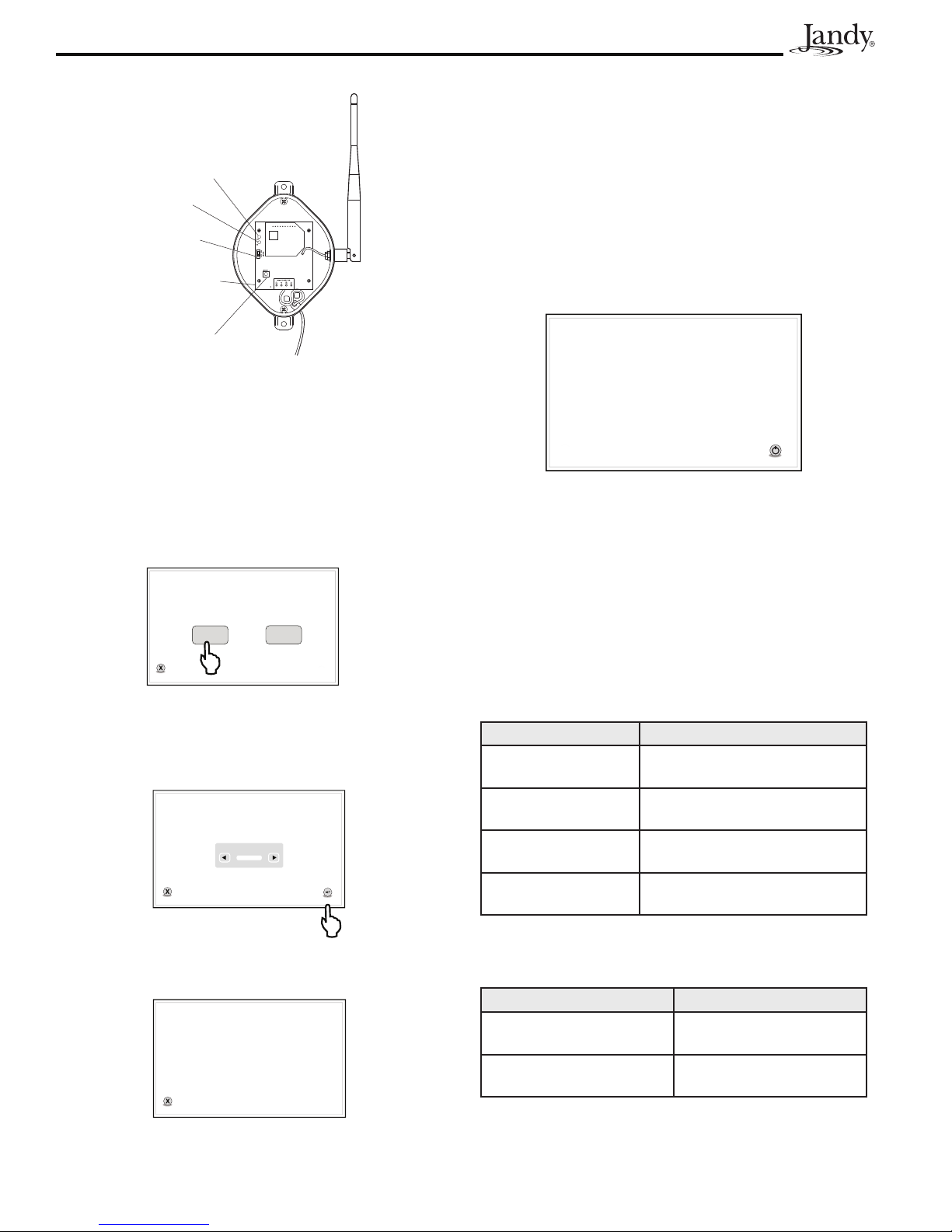
1. At the J-box, remove the cover to expose the PCB.
Page 18
Page 18
C
C
l
C
l
AquaLink® Touch™ and Operation Installation Manual
in J-Box to ON, then press the RESET button in the
J-Box.
Red LED
Green LED
Learn
Switch
Transceiver
PCB
Reset Switch
2. At the J-box, slide the Learn Switch to ON. If it is
not doing so already, the AquaLink Touch screen
will display the “waiting for connection…” screen
after a maximum of 10 seconds.
3. From the AquaLink Touch “waiting for
connection…” screen, touch the SETUP button.
The screen displays “what would you like to set?”.
4. Select “RF Channel”.
what would you like to set?
RF Channel
ancel
Power
Address
5. The AquaLink Touch screen displays “select
desired RF channel, then press ENTER." Using the
arrow buttons, select the desired channel then touch
ENTER.
select desired RF channel,
then press Enter.
RF Channel
7
ance
Enter
8. At the Transceiver J-Box, the Red and Green LEDs
fl ash alternately while the J-Box searches for the
correct channel.
9. When the correct channel is found, the J-Box LEDs
fl ash simultaneously and the AquaLink Touch
screen displays “channel found! set LEARN switch
in J-Box to OFF, then press J-Box RESET."
channel found!
set LEARN switch in J-Box to
OFF, then press J-Box RESET.
Power
10. At the Transceiver J-Box, return the Learn Switch
to OFF and press the J-Box RESET switch.
11. After a short time, the AquaLink Touch will return
to the “waiting for connection…” screen, then to
the home screen when connected successfully.
6.5.6 AquaLink Touch J-Box LED
Operation
Normal Operating Mode
Function LED Indication
Reset Both on continuous for 2
seconds
RS-485 Detected Both rapid blink simultaneously
for 2 seconds
Waiting for AquaLink
Touch Beacon
RS/AquaLink Touch
Communication
Green LED slow blink
Random blink of both LEDS
6. The AquaLink Touch screen displays “set LEARN
switch in J-Box to ON, then press J-Box RESET.”
set LEARN switch in J-Box to
ON, then press J-Box RESET.
scanning...
ance
7. If it is not already set to ON, set the LEARN switch
Channel Learn Mode
Function LED Indication
Searching for AquaLink
Touch channel
AquaLink Touch Channel
Learned
Alternate Red/Green blink
Both blink simultaneously
Page 19

AquaLink® Touch™ Installation and Operation Manual
Section 7. Troubleshooting
7.1 AquaLink Touch Troubleshooting Guide
Use the troubleshooting in for ma tion in the following table for suggestions.
Symptom Problem Possible Solution
Page 19
Power Center override switches
operate when in Service
or Time Out Mode, but the
AquaLink Touch controller is
completely dead (no display).
AquaLink Touch controller
backlight is on and the startup
screen is displayed. The
override switches at the power
center operate as they should.
AquaLink Touch controller
backlight is on and the "Waiting
for connection..." screen is
displayed, but override switch es
at the power center do not
operate at all.
No power to the AquaLink
Touch controller.
AquaLink Touch controller is
not communicating with the
power center PCB.
1. Damaged or improperly
installed CPU board.
2. Wrong CPU board.
3. Damaged power center
PCB.
Wired: Check the two (2) outer wires (red and
green) of the four (4) conductor cable from
the power center. The minimum desired input
voltage is 9VDC.
Wireless: Return AquaLink Touch to cradle to
begin recharging battery. Make sure the cradle is
plugged into a wall socket.
Wired: Check the cabling to the AquaLink Touch
(all conductors).
Wireless: Check the cabling to the J-box
transceiver (all conductors).
Wireless: Change the RF channel.
Wired and Wireless: In multiple AquaLink Touch
installations, verify each unit is set to a unique
address.
1. Check alignment of the CPU board.
2. Make sure that the CPU board is revision Q
or later.
3. If CPU board is installed correctly, replace the
power center PCB.
Some buttons do not operate
from the AquaLink Touch
controller, nor from the power
center override switches.
System locked up.
AquaLink Touch frozen at
"waiting for connection" screen.
Programs do not run at the
correct time.
Communication is lost. Signal Interference. The wireless AquaLink Touch controller will
Wrong CPU board installed at
the power center PCB.
Power center microprocessor
locked.
AquaLink RS does not display
correct time and date.
Make sure that the CPU board is revision Q or
later.
Turn off power to the system. Wait one (1)
minute and turn the power back on.
At the AquaLink Touch controller, set correct time
and date.
stop communicating anytime interference (such
as a 900 MHz device) prevents a valid signal
transmission. When communication is lost
the AquaLink Touch controller will lock on the
"waiting for connection..." screen until a good
link is again achieved, usually within a few
sec onds.
Page 20

H0325400 Rev C
CONFORMS TO ANSI/UL STD. 60950-1
CERTIFIED TO CAN/CSA STD. C22.2 NO. 60950-1
Zodiac Pool Systems, Inc.
6000 Condor Drive • Moorpark, CA USA 93021 • 800.822.7933 • Fax 877.327.4103
© Zodiac Pool Systems, Inc. 1001
 Loading...