

Page 1
MÁQUINA DUPLICADORA CAPRI
MANUAL DE INSTRUCCIONES
KEY CUTTING MACHINE CAPRI
INSTRUCTION MANUAL
MACHINE DUPLICATRICE CAPRI
NOTICE D’UTILISATION
DUPLIZIERMASCHINE CAPRI
BEDIENUNGSANLEITUNG
NØGLEMASKINE CAPRI
BRUGSANVISNING
MÁQUINA DUPLICADORA CAPRI
MANUAL DE INSTRUÇÕES
CAPRI
Page 2

ENGLISH
CAPRI
INSTRUCTION MANUAL
KEY CUTTING MACHINE
Page 3

ENGLISH
1.- PRESENTATION AND GENERAL ASPECTS
1.1 GENERAL POINTS
1.2 TRANSPORT AND PACKING
1.3 IDENTIFICATION LABEL
2. - CHARACTERISTICS OF THE MACHINE
2.1 FAMILIES OF KEYS
2.2 ACCESSORIES
2.3 TOOL STORE
2.4 ELECTRIC CIRCUIT
2.5 TECHNICAL DATA
2.6 MAIN ELEMENTS OF THE MACHINE
2.7 COMPONENTS AND FUNCTIONAL PARTS
2.7.1 CHANGING THE CUTTER AND TRACER POINT (21)
2.7.2 BLOCKING THE SLIDE AT THE END OF THE “Y” AXIS TRAVEL
2.7.3 CLAMP (6)
2.7.4 TRACER POINT SPRING MECHANISM (11)
2.7.5 SPRING MECHANISM AND BLOCKING THE SLIDE ON THE “X” AXIS (5 AND 4)
2.7.6 SUPPORT LEVER FOR TUBULAR KEYS
2.7.7 CUTTER SPEED (17)
2.7.8 KEYPAD-DISPLAY (1)
2.7.9 VERTICAL ADJUSTMENT OF THE TRACER POINT (15)
2.7.10 CONTROL OF CUTTING FORCE
3.- CUTTING
3.1 CUTTING PROCESS
3.2 KEY CUTTING
3.2.1 KA-2, KA-3 AND KA-4 KEYS.
3.2.2 KE-1 KEY.
3.2.3 SEA-1 KEY.
3.2.4 OP-WH.P AND OP-WY.P KEYS
3.2.5 ME-3.P AND ME-4.P KEYS
3.2.6 TUBULAR KEYS
3.2.7 FIC-2 AND FIC-3 KEYS
3.2.8 WIN-1D, WIN-2D, WIN-3D AND WIN-4D KEYS.
3.2.9 JIS-4.P KEY
3.2.10 FO-6.P KEY
3.2.11 MCM-10 KEY.
3.2.12 TE-T60 AND TE-T80 KEYS
4.- MAINTENANCE
4.1 REPLACING THE CLAMP JAWS
4.2 ADJUSTING THE JAWS
4.2.1 NORMAL ADJUSTMENT
4.2.2 PRECISION ADJUSTMENT
4.3 REPLACING THE FUSES
4.4 TIGHTENING AND REPLACING THE BELT
4.5 REPLACING THE MOTOR
4.6 REPLACING THE KEYPAD-DISPLAY
4.7 REPLACING THE ELECTRONIC CONTROL CARD
4.8 REPLACING THE POWER CARD AND CIRCUIT BREAKER
5.- SAFETY
6.- WASTE DISPOSAL
6.1 PACKING
6.2 SWARF
6.3 MACHINE
7.- KEY-CUTTER-TRACER POINT-ANGLE CUT-ADAPTOR TABLE
8.- EXPLODED VIEW
Page 4

ENGLISH
1.- PRESENTATION AND GENERAL ASPECTS
1.1 GENERAL POINTS
The CAPRI key cutting machine has been designed on the basis of safety standards
currently in force in the EU.
The safety of the personnel involved in handling this type of machines can only be
achieved with a well designed worker safety programme, like the implementation of
a maintenance programme and following recommended advice as well as compliance
with the safety standards included in this manual.
Although the machine is not difficult to install, it is best not to try to install, adjust or
use it without having first read this manual.
The machine leaves our factory ready for use and only requires calibration operations
for the tools that are going to be used.
1.2 TRANSPORT AND PACKING
The machine comes in a robust cardboard box protected with packing foam with the
following dimensions:
Width = 520 mm; Height = 650 mm; Depth = 575 mm
Weight of machine plus packing = 30 Kg.
When you unpack the machine, check carefully to see if it has suffered any damage
during transportation.
If you find any problems, please inform the carrier immediately and do not do anything
with the machine until the carrier’s agent has carried out an inspection.
To move the machine from one place to another, get hold of the machine by the base,
and not by any other part.
1.3 IDENTIFICATION LABEL
The CAPRI key cutting machine has an identification label, giving the machine’s serial or
registration number, the manufacturer’s name
and address, the CE mark and year of manufacture.
2. - CHARACTERISTICS OF THE MACHINE
The CAPRI machine is a highly robust and precision key cutting machine, which stands
out for having a clamp that enables many different types of keys to be clamped, without
the need for any adaptors.
It incorporates a novel force control system, which increases cutting precision.
2.1 FAMILIES OF KEYS
The CAPRI machine cuts the following types of keys, among others:
- Dimple keys
- Wave keys
- Tubular keys
- FIC-2 and FIC-3 keys
- WIN-1D, WIN-2D, WIN-3D and WIN-4D keys
- JIS-4.P keys
- FO-6.P keys
2.2 ACCESSORIES
The machine is supplied with a number of accessories for its use and maintenance. All
these accessories can be housed in the machine’s tool store.
- 2 fuses (housed in the bottom of the tool store)
- Set of Allen keys (5, 3 and 2.5)
- 1 special 1.5 short-arm Allen key
- 2 tip-stop strips
- 2 jaw adjustment rods.
- 2 adaptors for CHI-1T tubular key
- Cutters: F-1 and F-13
- Tracer points: T-1 and T-13.
2.3 TOOL STORE
The machine has a tool store, which is fitted to the top of the machine. It can be removed and laid directly on a table (in this way providing extra space on top of the machine,
which can be used for keeping keys, accessories, etc…).
2.4 ELECTRIC CIRCUIT
The main components of the electric and electronic circuits are as follows:
Socket.
Connection plate.
3-position switch.
Transformer.
Motor.
Keypad-display.
Control card.
Cutter.
Tracer point.
Clamp.
Lighting LED.
Force sensor.
See Figure 2
2.5 TECHNICAL DATA
Motor: Single phase 400 W. ,230 V - 50 Hz (Optional: Single phase 400W, 110V – 60Hz)
Cutter: HSS (Optional: Hard metal)
Cutter speed: 6,000 and 11,000 r.p.m.
Clamps: Two clamping faces and 0 / 45 º tilting
Displacement: On three axes with precision roller guides.
Effective stroke: X axis = 71 mm; Y axis = 62 mm; Z axis = 40 mm
Lighting: LED
Dimensions: Width = 430 mm, Depth = 385 mm and Height = 485 mm
Weight: 25 Kg
2.6 MAIN ELEMENTS OF THE MACHINE
1.- Keypad-display
2.- Clamp-holder slide (X – Y axes)
3.- Slide activation lever, x – y axes
4.- Knob to block clamp-holder slide, x axis
5.- Slide spring mechanism activation wheel, x-axis
6.- Clamp
7.- Lever to block clamp rotation
8.- Clamp knob
9.- Head (Z axis)
10.- Lever to activate and block head, z axis
11.- Tracer point spring mechanism knob
12.- Tool-holder
13.- Cutter
14.- Tracer point
15.- Tracer point height adjustment wheel
16.- Main switch
17.- Motor speed selector (2 speeds)
18.- Lighting LEDs
19.- Swarf protector
20.- Tool store
21.- Cutter blocking button
See Figure 3
2.7 COMPONENTS AND FUNCTIONAL PARTS
2.7.1 CHANGING THE CUTTER AND TRACER POINT (21)
To release the cutter, you have to press the cutter blocking button and at the same time
rotate the tool-holder by hand.
After removing the cutter to be replaced, insert the new cutter and secure it in the toolholder, making sure that its end butts up against the inside of the tool-holder.
The tracer point is replaced in the same way as the cutter. The only difference to bear in
mind is that the rotation of the tracer point is always blocked internally.
2.7.2 BLOCKING THE SLIDE AT THE END OF THE “Y” AXIS TRAVEL
In order to prevent the slide from moving in the “Y” direction, whilst the key cutting
machine is holding the keys in the clamp, the slide has been equipped with momentary
blocking in that direction.
To active this blocking, just move the slide as far as it will go in the direction towards
to the key cutting machine.
To deactivate the blocking, just move the slide forward, exercising a little force.
2.7.3 CLAMP (6)
The features of the clamp on the CAPRI key cutting machine are superior to those of any
normal machine on the market, as it has two separate clamping faces. In addition, the
clamps can be blocked in any rotation position between 45º 0º -45º.
2.7.4 TRACER POINT SPRING MECHANISM (11)
The tracer point can be used in two different ways, depending on the work you are
going to do:
Page 5
ENGLISH
- Tracer point with spring mechanism. The tracer point spring mechanism is
only used for cutting dimple keys.
- Tracer point blocked. The blocked tracer point is used to carry out cutting
operations with the slide forward. In general, for cutting wave keys.
To activate or deactivate the tracer point spring mechanism, you just have to turn the
tracer point spring mechanism knob 180º (half turn).
When the tracer point spring mechanism is activated, the tracer point tip is located
slightly below its adjustment position in relation to the cutter. This tracer point position
enables you to insert it gently into the hole in the original key, before the cutter starts
cutting the key to be copied. This avoids any vibrations and sudden movements of the
slide.
To find out the status of the tracer point at any time (with spring mechanism or blocked),
there is an indicator on the machine’s keypad-display which provides this information. If
the light is on, the spring mechanism is activated. On the other hand, if the light is off,
the tracer point is blocked.
2.7.5 SPRING MECHANISM AND BLOCKING OF THE SLIDE ON THE
“X” AXIS (5 AND 4)
We recommend that you use the spring mechanism for the slide on the “X” axis to carry
out lateral cutting of wave keys.
We recommend you use the blocking of the slide on the “X” axis for cutting or dimpling
in a straight line.
2.7.6 SUPPORT LEVER FOR TUBULAR KEYS
The CAPRI key cutting machine has a fold-away lever on its top-left side which helps to
make cutting tubular keys, wave keys, etc. more comfortable, as it serves as a support
point for the hand activating the slide travel lever.
2.7.7 CUTTER SPEED (17)
The machine has a speed selector on its right side, which enables you to select the
cutter rotation speed. In general terms, you can say that the rotation speed depends
on the cutter material:
- Position I: To work with an HSS cutter (6,000 rpm)
- Position II: To work with a HARD METAL cutter (11,000 rpm)
- Position O: Cutter at rest.
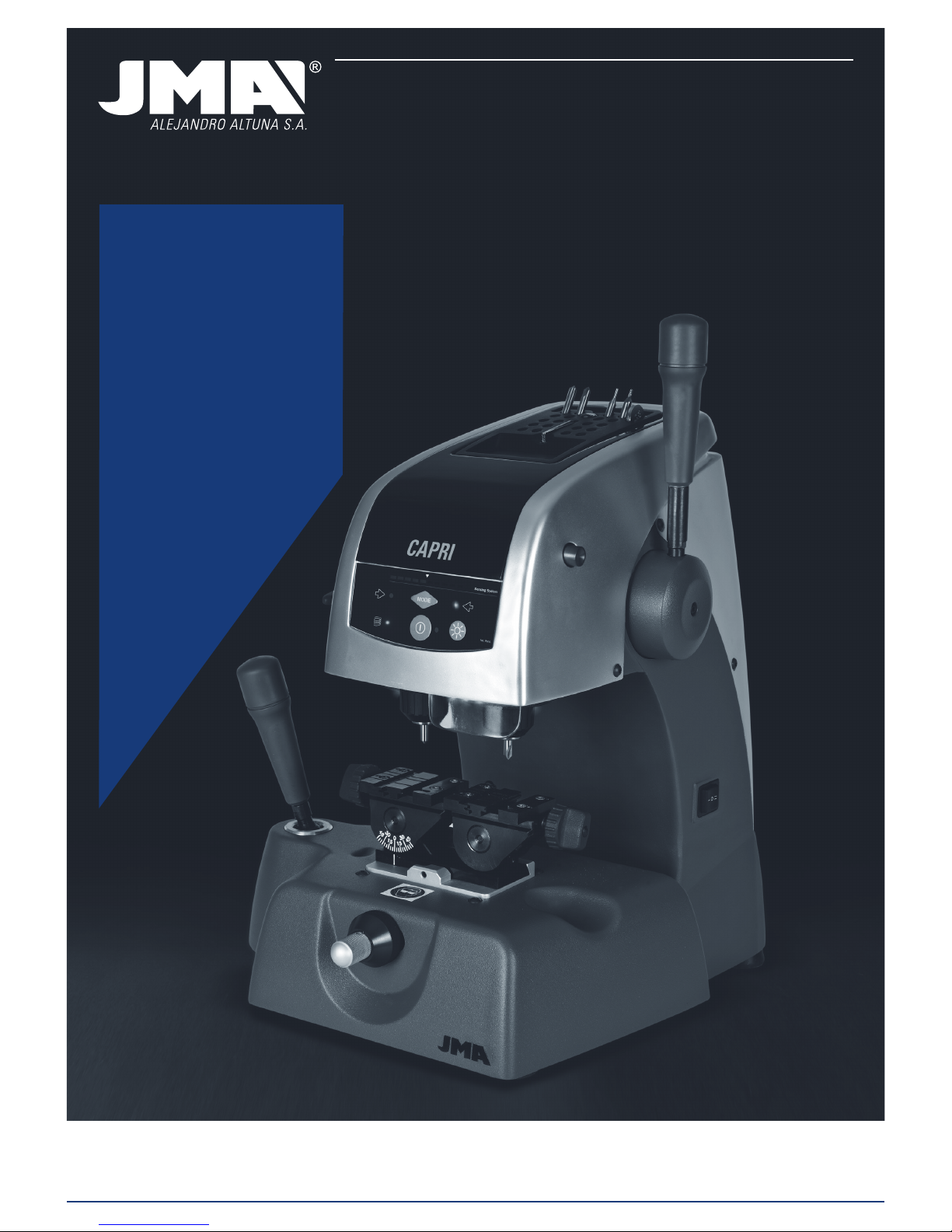
2.7.8 KEYPAD-DISPLAY (1)
ON-OFF button
Press it for the keypad-display functions to go into ACTIVE mode. A green light will
appear next to the button.
Press it again for the keypad-display to go into STAND-BY mode. A red light will appear
next to the button.
Lighting button
Press it to switch on the lighting diodes (if they are off) or switch them off if they are on.
This button operates independently of the status of the “ON-OFF” button.
SPRING MECHANISM indicator
If the blue light is on, this means that the tracer point is in SPRING MECHANISM ACTIVATED mode.
If the blue light is off, this means that the tracer point is BLOCKED (spring mechanism
deactivated).
MODE button
This button is for activating-deactivating operation of the tracer point vertical adjustment system.
TRACER POINT ADJUSTMENT indicators.
The light on the left comes on when the tracer point is touching the key.
The light on the right comes on when the cutter is touching the key.
FORCE visual indicator.
Indicates the ideal force to be applied during cutting.
NOTE: In addition to the visual indicator, the force control system also has an audible
indicator that emits a sound when you have achieved the ideal cutting force. This audible indicator can be activated-deactivated by pressing the MODE and ON-OFF buttons
at the same time.
2.7.9 VERTICAL ADJUSTMENT OF THE TRACER POINT (15)
Each time the cutter-tracer point is changed, the tracer point has to be vertically adjusted.
In order to be able to use the tracer point electronic vertical adjustment system, the
keypad-display must be active (when it is active, a green light appears next to the
ON-OFF button).
When the keypad-display is active, you can activate-deactivate the tracer point electronic vertical adjustment system by pressing the MODE button.
To vertically adjust the tracer point, proceed as follows:
• Secure the cutter and tracer point in their corresponding tool-holders. Make sure
that they have been secured, inserted upwards as far as they go.
• Secure two similar keys in the machine clamps.
• Release the tracer point spring mechanism (tracer point blocked).
• Lower the head, until the cutter and the tracer point rest on the keys in the
clamps. Then, one of the following three situations will occur:
LEFT BLUE LIGHT. If only the blue light on the left comes on, this means that
the tracer point is touching the key, but the cutter is not. Therefore, you have to
turn the cutter adjustment wheel to the left, until both adjustment lights some on.
RIGHT BLUE LIGHT. If only the blue light on the right comes on, this means that
the cutter is touching the key, but the tracer point is not. Therefore, you have to
turn the tracer point adjustment wheel to the right, until both adjustment lights
come on.
LEFT AND RIGHT BLUE LIGHTS. This means that both the cutter and tracer
point are touching their respective keys. This means that the height of the tracer
point has been adjusted.
IMPORTANT NOTE: When adjusting the height of the tracer point, you need to bear
in mind the type of key you are going to cut. If it is a WAVE key, very little force needs
to be applied to the head activation lever (on the visual force indicator no light should
come on). On the other hand, if it is a DIMPLE key, the blue adjustment lights have to
come on, and the force indicator should indicate the ideal cutting force for dimple keys
(to achieve this, you have to apply a slight force on the head activation lever).
2.7.10 CONTROL OF CUTTING FORCE
The CAPRI machine has a revolutionary cutting force control system. This is a patented
system, which when you are cutting DIMPLE keys, indicates the ideal force to exercise
on the head activation lever. It has two indicators for this purpose:
Visual indicator. The ideal cutting force is achieved when the line of lights reaches the white arrow.
Audible indicator. When the line of lights reaches the white arrow, the machine
emits a sound. This audible indicator can be activated-deactivated by pressing the
MODE and ON-OFF buttons at the same time.
This cutting force control system enables you to cut DIMPLE keys with great precision.
You will cut the holes in the key with exactly the same force with which you have
adjusted the height of the tracer point. In this way, you obtain maximum precision in
cutting DIMPLE keys.
3.- CUTTING
3.1 CUTTING PROCESS
• Switch on the machine using the main switch located on the back right-hand side
of the machine.
• To improve visibility in the work area, activate the lighting by turning on the switch
located on the keypad-display.
• With the help of the table provided in this manual, select the cutter and tracer
point necessary to cut the key.
• Change the cutter and tracer point.
• Momentarily block the slide at the end of the “Y” axis travel.
• Secure the original key in the left side of the clamp, and the key to be cut in the
right side. When securing the keys, bear in mind the following details:
- KEY STOP. It may be a key which is stopped from being inserted further by its
shoulders (Fig. 4.A), or a key stopped by its tip (Fig. 4.B).
- ADAPTOR. For some very specific types of key, it may be necessary to use an
adaptor.
Page 6

ENGLISH
- ANGLE CUT. Some keys have angle cut dimples, for which it is necessary to
rotate the clamp.
• Carry out the vertical adjustment of the tracer point.
• Activate the systems which simplify the cutting work:
TRACER POINT: Activate or deactivate the tracer point spring mechanism,
depending on the type of key being cut.
SLIDE: Based on the model of key, it may be a good idea to activate the slide
spring mechanism, or block the slide in the “X” direction.
SUPPORT: Depending on the type of key, it may be a good idea to use the support
lever for tubular keys.
• Start rotating the cutter, having first selected one of the two speeds available.
• Proceed to cut the key. If it is a dimple key, use the help of the cutting force
control system.
3.2 CUTTING KEYS
3.2.1 KA-2, KA-3 AND KA-4 KEYS.
• Different pairs of cutters and tracer points are used depending on the key to be cut.
See table.
• The key is secured in the clamp when its shoulders stop it from being inserted any
further.
• Depending on the model of key to be cut, it is necessary to rotate the clamps based
on the angle required. See table.
• It is necessary to activate the tracer point spring mechanism.
• Use the cutting force control system to increase cutting precision.
• NOTE: The dimples cut on the KA-3 key must always be on the lowest part of the
clamp.
• NOTE: The dimples cut on the KA-2 key must always be on the highest part of the
clamp.
See Fig. 5
3.2.2 KE-1 KEY.
• Use cutter-tracer point pair: F-1 / P-1.
• The key is secured in the clamp when its shoulders stop it from being inserted any
further, but in this case it is inserted from the back.
• It is necessary to position the clamps at an angle of 5º.
• It is necessary to activate the tracer point spring mechanism.
• Use the cutting force control system to increase cutting precision.
• NOTE: The dimples cut on the KE-1 key must always be on the highest part of the
clamp.
• NOTE: You have to use the relevant adaptor to cut the lateral dimples.
See Fig. 6
3.2.3 SEA-1 KEY.
• Use cutter-tracer point pair: F-3 / P-3.
• The key is secured in the clamp when its shoulders stop it from being inserted any
further.
• It is necessary to block the tracer point (deactivate the spring mechanism).
• NOTE: After vertically adjusting the tracer point, you need to slightly lower the
tracer point, by turning the adjustment wheel 5 points to the right. Then you have to
insert the tracer point in the channel of the bit and block the machine head. Next slightly
raise the tracer point so that it does not drag the key.
• NOTE: Enter through the middle of the channels without touching the sides, and on
the second pass enter from the right side and exit from the left, without exercising any
pressure (just gently supporting the tracer point).
• NOTE: To cut the lateral dimples, use the cutter-tracer point combination: F-1 /
P-1. Insert until shoulders stop the key from going in any further. Activate the tracer
point spring mechanism and use the cutting force control system.
See Fig. 7
3.2.4 OP-WH.P AND OP-WY.P KEYS
• Use cutter-tracer point pair: F-11 / P-11.
• The key is secured in the clamp when its tip stops it from being inserted any further.
• It is necessary to block the tracer point (deactivate the spring mechanism).
• NOTE: After vertically adjusting the tracer point, you need to slightly lower the
tracer point, by turning the adjustment wheel 5 points to the right. Then you have to
insert the tracer point in the channel of the bit and block the machine head. Next slightly
raise the tracer point so that it does not drag the key.
• NOTE: We recommend using the slide spring mechanism system.
• NOTE: We recommend you do a roughing pass and then another finishing pass
following the whole profile of the pattern of the key. Machine in a downward direction
(from the tip of the key to the head).
See Fig. 8
3.2.5 ME-3.P AND ME-4.P KEYS
• Use cutter-tracer point pair: F-11 / P-11.
• Secure the key in the clamp using the AD-MM2 adaptor.
- Position the adaptor on the clamp, so that it is stopped by the tip.
- Insert the key into the adaptor.
- As you secure the adaptor in the clamp, the key is secured in the adaptor.
• It is necessary to block the tracer point (deactivate the spring mechanism).
• NOTE: After vertically adjusting the tracer point, you need to slightly lower the
tracer point, by turning the adjustment wheel 5 points to the right. Then you have to
insert the tracer point in the channel of the bit and block the machine head. Next slightly
raise the tracer point so that it does not drag the key.
• NOTE: We recommend using the slide spring mechanism system.
See Fig. 9
3.2.6 TUBULAR KEYS
• Use cutter-tracer point pair: F-8 / P-8.
• Secure the key in the clamp “V”.
• It is necessary to activate the tracer point spring mechanism.
• The cutting operation is more comfortable if you rest the hand activating the slide
activation lever on the support lever for tubular keys.
See Fig. 10
3.2.7 FIC-2 AND FIC-3 KEYS
• Use cutter-tracer point pair: F-11 / P-11.
• Secure the key in the clamp, resting it against the bottom and pushing it towards
the front face of the clamp.
• It is necessary to block the tracer point (deactivate the spring mechanism).
• Block the machine head at a height at which the cutter passes over the clamp but
without brushing against it.
• Cut the two top sides.
• Turn the keys taking care to remove any burrs to ensure correct positioning and
clamping of the key, and cut the other two sides of the key.
See Fig. 11
3.2.8 WIN-1D, WIN-2D, WIN-3D AND WIN-4D KEYS.
• Use cutter-tracer point pair: F-15 / P-15.
• Secure two key blanks in the clamp, and use them to vertically adjust the tracer
point.
• Clamp the original key with the teeth facing upwards (as shown in the drawing).
• It is necessary to block the tracer point (deactivate the spring mechanism).
• Insert the tracer point precisely in one of the dimples, and block the machine head
at that height.
• Start cutting.
See Fig. 12
3.2.9 JIS-4.P KEY
• Use cutter-tracer point pair: F-11 / P-11.
• Secure the key in the clamp using the AD-MJ adaptor.
-Position the adaptor on the clamp, so that it is stopped by the tip.
-Insert the key into the adaptor, until its shoulders are stopped by the plate that
rotates. In this position, clamp the key in the adaptor.
• It is necessary to block the tracer point (deactivate the spring mechanism).
See Fig. 13
3.2.10 FO-6.P KEY
• Use cutter-tracer point pair: F-22 / P-22.
• Secure the key in the clamp, using the relevant adaptor.
- Position and secure the adaptors on the clamp.
- When positioning the key, make sure that it is really flat, so that the two cuts
are the same.
• It is necessary to block the tracer point (deactivate the spring mechanism).
• Insert the tracer point if the groove of a letter. Block the machine head and raise
the tracer point slightly so that it does not knock against the adaptor.
• Start cutting.
See Fig. 14
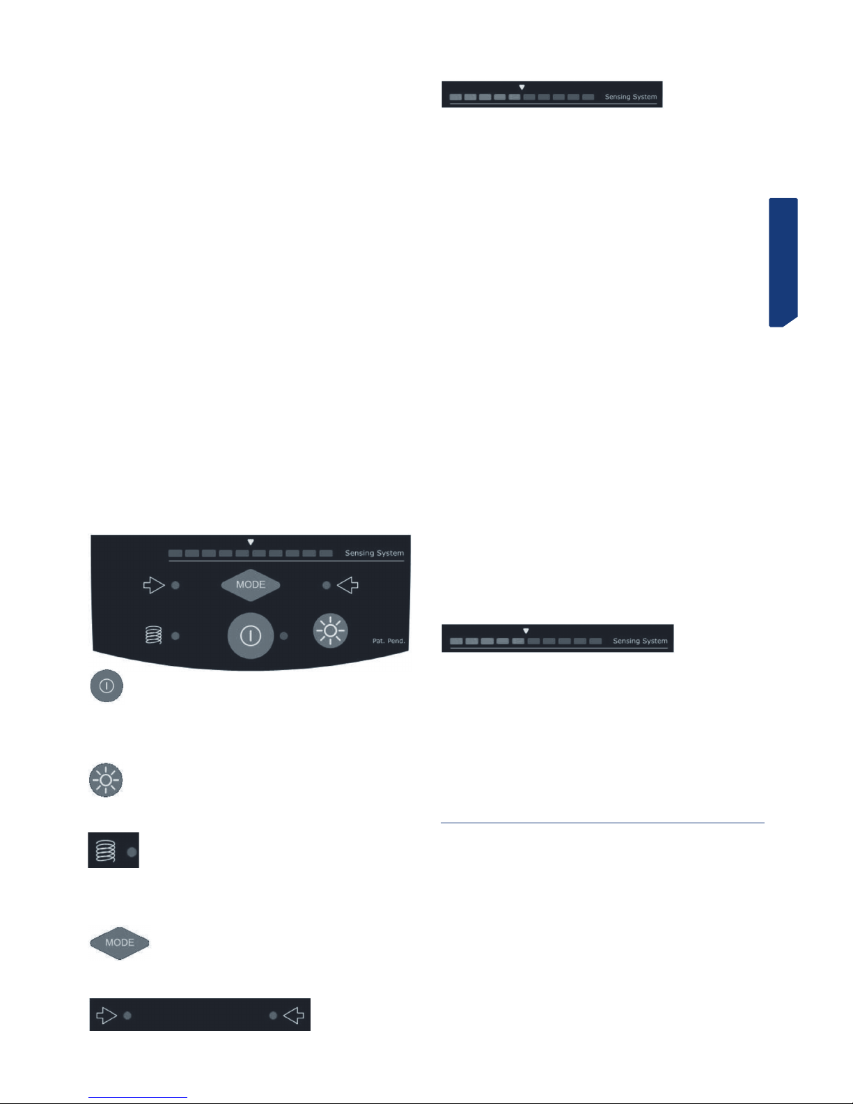
Reading the code on the original key
• The original key has 6 cutting positions, which are defined by the letters: A, B, C, D, E
and F, as shown in the figure below.
• In each of the key’s positions, there are 4 different possible combinations (defined by
numbers), which we are going to indicate and number:
Page 7
ENGLISH
1 2 3 4
• Height no. 1, indicates that it should not be cut. Position no. 2 indicates there is a
small notch in the key and when it is slightly deeper this is position no. 3. Height no. 4
is the deepest notch in the key.
• You then take the key and mark the combinations of each of the 6 positions, as
shown below, by way of example:
POSITION A B C D E F
COMBINATION 3 4 1 2 4 2
NOTE: The series of combination numbers is the key code.
3.2.11 MCM-10 KEY.
• Special positioning in the clamp. See figure.
See Fig.15
3.2.12 TE-T60 AND TE-T80 KEYS
• Special positioning in the clamp. The TE-T60 is clamped as shown in the drawing.
• The TE-T80 key has the peculiarity that to machine the left side it is clamped like
the TE-T60 and to machine the right side the key has to be clamped by the back part of
the clamp (like with the MCM-10 key).
See Fig. 16
4.- MAINTENANCE
When carrying out any maintenance work, it is necessary to meet the following requirements:
1. Never carry out any maintenance work with the machine switched on.
2. Unplug the machine.
3. Strictly adhere to the indications in this manual.
4. Only use original spare parts.
4.1 REPLACING THE CLAMP JAWS
The CAPRI machine’s clamp has three pairs of jaws (left fixed jaw, right fixed jaw and
moving jaw). If any of them become damaged, you can replace them with new jaws,
separately.
To replace the left fixed jaw (A) or the right fixed jaw (B), you just have to undo the two
screws securing them, and remove them by pulling them upwards. Reverse the process
to fit the new jaws.
To replace the moving jaw (C), you need to follow the steps below:
1) With the help of a cutter or something similar, remove the clamp knob’s black
plastic cover.
2) Whilst locking the locknut with a size 14 spanner, insert a no. 5 Allen key into the
hole revealed in the clamp knob, and unscrew it.
3) Tilt the clamp 45º, and manually turning the spindle, remove it from one of the
sides. Once the spindle has been removed, the moving jaw is released and you can
remove it.
4) To fit the new moving jaw, simply reverse the process.
IMPORTANT NOTE: When you replace the left fixed jaw or the right fixed jaw, you
always have to adjust the pair of jaws that has been replaced. On the other hand, if you
replace the moving jaw, it is not necessary to carry out any adjustment on the jaws.
See Fig. 17
4.2 ADJUSTING THE JAWS
Whenever you replace the left fixed jaw or the right fixed jaw, you have to adjust the
pair of jaws that has been replaced. On the other hand, the replacement of the moving
jaw does not require any adjustment to the jaws.
There are two different ways of adjusting the jaws:
NORMAL adjustment
PRECISION adjustment
4.2.1 NORMAL ADJUSTMENT
This is a quick, simple adjustment, which will give you an acceptable adjustment
enabling you to cut keys with a certain amount of precision.
To carry out this adjustment, follow these steps:
1) Secure the two adjustment rods in their relevant tool-holders, inserting then as far
as they will go into the tool-holder, with the tapered part of the adjustment rods on the
outside.
2) The left fixed jaw on the right-hand side of the clamp and the right fixed jaw on the
left-hand side of the clamp cannot be adjusted, as they are held in position by means
of pins. So you have to fit them, by guiding them with their pins and then securing them
with their corresponding screws.
3) Therefore, knowing that in each pair of jaws there is one with a fixed position, you
have to adjust the other jaw in relation to the one with the fixed position.
4) Insert the screws for the jaw to be adjusted, but do not tighten them. So that the
jaw can be moved by hand, but cannot lift up from the surface it is resting on.
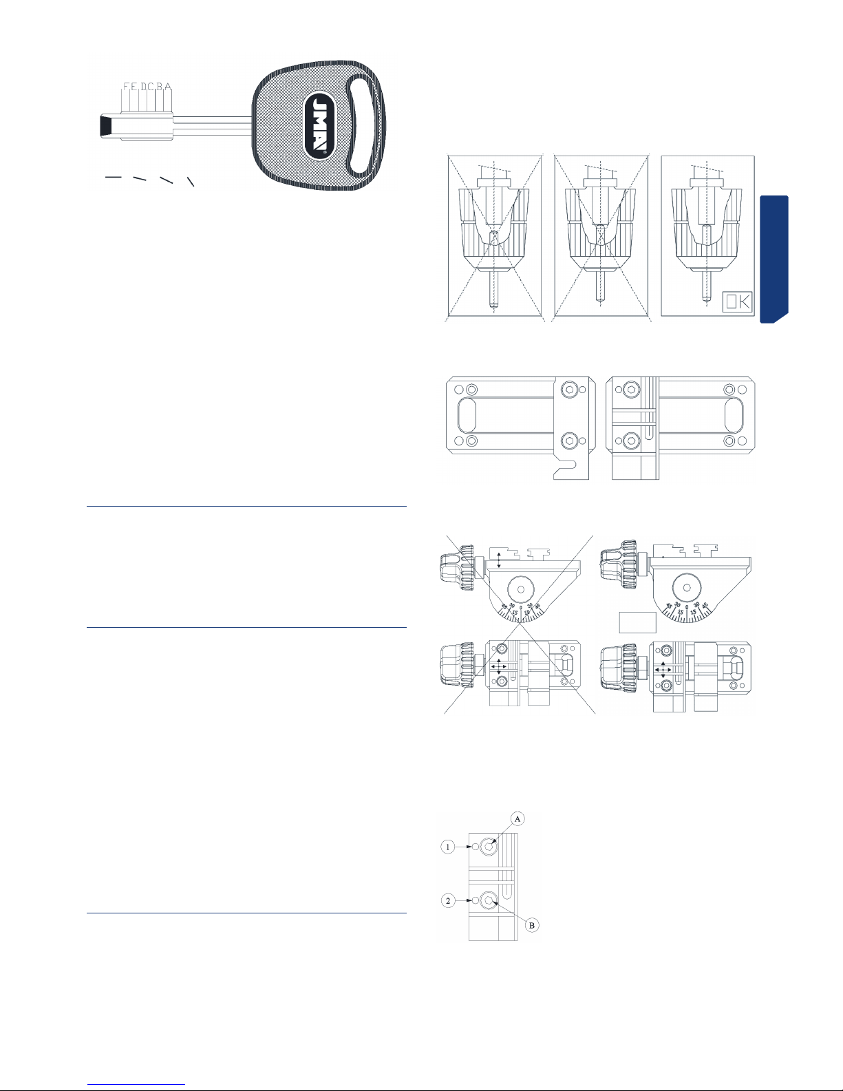
5) Adjust the jaw:
5.1) Insert the tracer point adjustment rod into hole no. 1 in the jaw.
5.2) Make the cutter adjustment rod coincide with hole no. 1 in the other jaw.
5.3) Raise the head and carry out the same operation, with hole no. 2 in the jaws.
5.4) Repeat this operation as many times as necessary until the adjustment rods
enter smoothly without the need for any force, in both hole no. 1 and hole
no. 2.
5.5) With the two adjustment rods inserted in holes no. 1, block the head, and
slightly tighten screw B.
5.6) With the two adjustment rods inserted in holes no. 2, block the head and
slightly tighten screw A.
5.7) Repeat the above operation, but fully tightening screws A and B.
5.8) Once you have completed the adjustment process, with the help of the special
short-arm 1.5 Allen key, tighten the two setscrews located between the clamp
knob and the jaw you have adjusted. This will ensure that the jaw you have adjusted is tightly secured.
Page 8

ENGLISH
4.2.2 PRECISION ADJUSTMENT
This adjustment requires a certain amount of skill, and ensures that the replaced jaws
are very precisely adjusted.
To carry out this adjustment, follow these steps:
1) The left fixed jaw on the right-hand side of the clamp and the right fixed jaw on the
left-hand side of the clamp cannot be adjusted, as they are held in position by means
of pins. So you have to fit them, by guiding them with their pins and then securing them
with their corresponding screws.
2) Therefore, knowing that in each pair of jaws there is one with a fixed position, you
have to adjust the other jaw in relation to the one with the fixed position.
3) Insert the screws for the jaw to be adjusted, but do not tighten them. So that the
jaw can be moved by hand, but cannot lift up from the surface it is resting on.
4) With the help of the special short-arm 1.5 Allen key, unscrew the two jaw adjustment setscrews about 1 turn (these are the two setscrews located between the
clamp knob and jaw you are going to adjust).
5) Then, insert any cutter-tracer point pair in their corresponding tool-holders, but
the wrong way around (with the cutting tips inside the tool-holder). Lower the machine
head, and block it at a height at which the tools can touch the sides of the jaws.
6) Activate the tracer point electronic vertical adjustment system.
7) Rest the end of the jaw that is clamped (the one with the fixed position) against
the side of the tool. Manually, move the jaw to be adjusted in the direction of the clamp
knob, and maintaining pressure on the jaw in that direction, move it forward until it also
touches the side of its corresponding tool. In this position, tighten the screws securing
the jaw a little. You will know when the tools are touching their corresponding jaws,
because the tracer point electronic vertical adjustment system’s lights will come on.
8) Then, separate the moving jaw from the jaw to be adjusted, turning the clamp knob
to do so.
9) Position the tool in alignment with one of the screws securing the jaw, and in this
position rest the tool against the jaw that is clamped (the one with the fixed position).
Then, keeping at all times a slight pressure between the tool and the jaw that is clamped (the one with the fixed position), very slowly tighten the setscrew aligned with the
tool and the jaw screw. The moment will come when the second light on the tracer point
electronic vertical adjustment system will come on. When this happens, stop tightening
the setscrew.
10) Position the tool in alignment with the other screw securing the jaw, and carry out
the same operation again.
11) Check again that the jaws are adjusted in those two positions (in front of the
clamping screws), and if necessary, slightly adjust the position of the jaw tightly very
slightly the corresponding setscrew.
12) You have now completed the adjustment. Now you have to fully tighten the two
screws securing the jaw.
13) Finally, tighten the two jaw adjustment setscrews a little. This will ensure that the
jaw you have adjusted is tightly secured.
4.3 REPLACING THE FUSES
If the machine does not start when you activate the on-off switches, you need to check
the fuses. You can do this in the following way:
1) Switch of the machine using the main switch and unplug it.
2) Remove the fuse-holder which is under the main switch.
3) Use a tester to check if a fuse has blown and, if so, replace it with one of the same
type and value.
4.4 TIGHTENING AND REPLACING THE BELT
To check the tightness of the belt or to replace it, follow these steps:
1) Switch off the machine using the main switch, and unplug it.
2) Undo the 4 screws (5) securing the head guard and remove it. The screws are on
the right side, the left side, on the top and at the back. To remove the head guard it is
necessary first of all to push the cutter locking button right in as far as it will go (E).
3) Loosen but do not undo the 4 screws (6) securing the motor.
4) Loosen but do not undo the 2 locknut nuts (7).
Tightening: When you turn the two tightening screws (8), the motor moves towards
the back of the machine. When you see that the belt is tight enough, tighten up the two
locknut nuts (7) again, and the screws (6) securing the motor.
Replacement: Loosen but do not undo the 2 screws tightening the belt (8). Remove the
damaged belt and replace it with a new one. When you turn the two tightening screws
(8), the motor moves towards the back of the machine. When you see that the belt is
tight enough, tighten up the two locknut nuts (7) again, and the screws (6) securing
the motor.
5) Put the head guard back and secure it in place.
See Fig. 18
4.5 REPLACING THE MOTOR
You can carry out this operation in the following way:
1) Switch off the machine using the main switch and unplug it.
2) Undo the 4 screws (5) securing the head guard and remove it. The screws are on
the right side, the left side, on the top and at the back. To remove the head guard it is
necessary first of all to push the cutter locking button right in as far as it will go (E).
3) Undo the 6 screws (9) securing the motor guard (F) and remove it.
4) Remove the belt (G).
5) Disconnect the power cables going to the motor.
6) Undo the 4 screws (6) securing the motor.
7) Remove the motor.
8) Access the bottom of the motor with a flat screwdriver, block the motor shaft and
manually turn the pulley (H) until it comes out (it is left-threaded).
9) Undo the 4 screws (10) securing the motor support plate and remove it.
10) To fit the new motor, reverse the procedure above.
See Fig. 19
4.6 REPLACING THE KEYBOARD-DISPLAY
You can carry out this operation in the following way:
1) Switch off the machine using the main switch, and unplug it.
2) Undo the 4 screws (5) securing the head guard and remove it. The screws are on
the right side, the left side, on the top and at the back. To remove the head guard it is
necessary first of all to push the cutter locking button right in as far as it will go (E).
3) Disconnect the flat cable connecting the keypad-display (K) to the electronic control card.
4) Release the old keypad-display (K) from the head guard and remove it.
5) To fit the new keypad-display, reverse the procedure above.
See Fig. 20
Page 9

ENGLISH
4.7 REPLACING THE ELECTRONIC CONTROL CARD
You can carry out this operation in the following way:
1) Switch off the machine using the main switch and unplug it.
2) Undo the 4 screws (5) securing the head guard and remove it. The screws are on
the right side, the left side, on the top and at the back. To remove the head guard it is
necessary first of all to push the cutter locking button right in as far as it will go (E).
3) Disconnect the electronic control card’s main connector (L)
4) Disconnect the flat cable connecting the keypad-display (K) to the electronic control card
5) Undo the 3 screws (11) securing the electronic control card (L) to the head guard
and remove it.
6) To fit a new electronic control card, reverse the procedure above.
See Fig. 21
4.8 REPLACING THE POWER CARD AND CIRCUIT
BREAKER
You can carry out this operation in the following way:
1) Switch off the machine using the main switch and unplug it.
2) Unscrew the machine’s 4 feet (P) and remove them.
3) Undo the 5 screws (12) the lower protection plate and remove it.
4) Disconnect all the cables from the card you want to replace, noting down beforehand the position of each cable.
5) To release the power card (M) or the circuit breaker (N), just press on the lugs on
each of the 4 pins holding it, and pull the card up.
6) To fit the new power card or circuit breaker, just reverse the procedure above.
See Fig. 22
5.- SAFETY
For your safety, we recommend that you follow these guidelines:
• Do not try and start or operate the machine until all the safety aspects, installation
instructions, operators’ guide and maintenance procedures have been complied with
and understood.
• Always disconnect the mains electricity supply, before carrying out any cleaning or
maintenance work.
• Always keep the machine and the area around it clean.
• Work with dry hands.
• Use protective goggles, even if the machine is fitted with guards.
• Make sure that the machine has an earth connection.
We recommend that you work with the machine at a height at which you feel comfortable:
• It is best to work whilst sat in a chair. Adjust the height of the chair so that your
eyes are at the height of the highest part of the machine.
• If you work standing up, depending on your height, it is advisable to place something between the table and the machine to raise the machine so that your eyes are
level with the highest part of the machine.
6.- WASTE DISPOSAL
Waste is understood to be any substance or object from human activities or natural
cycles, that is no longer being used or not intended for any further use.
6.1 PACKING
• As the packing the CAPRI comes in is made of cardboard, it can be recycled as
packing.
• As waste, it is comparable to solid urban waste and, therefore, can only be disposed in special containers for cardboard.
• The elements protecting the machine inside the cardboard box are made of polymeric material comparable to solid urban waste and, therefore, can only be disposed of
in the normal installations for waste disposal.
6.2 SWARF
• The waste from the key cutting process is classified as special waste, but is comparable to solid urban waste, like for example a metal scouring pad.
• This waste shall be disposed of as classified by the laws currently in force in the
EU, by taking it to special installations for waste disposal.
6.3 MACHINE
• Before demolishing the machine it is necessary to put it out of action first, cutting
off the electricity supply and separating the plastic parts from the metal parts.
• After carrying out this operation, all the waste can be disposed of in compliance
with the laws in force in the country in which the machine was used.
7.- KEY-CUTTER-TRACER POINT-ANGLE CUTADAPTOR TABLE
To be able to do the work properly, the machine has a series of accessories:
See final list.
8.- EXPLODED VIEW
See Fig. 23
Page 10

2
3 4.A
4.B
Page 11

5
6
7
9 10
8
Page 12

11
14
16 17
15
12
13
Page 13

18
20 21
22
19
Page 14

23
Page 15

REFERENCIA
REFERENCE
REFERENCE
ARTIKELNUMMER
REFERENCE
REFERÊNCIA
MARCA
MANUFACTURER
MARQUE
HERSTELLER
MÆRKE
MARCA
FRESA
CUTTER
FRAISE
FRÄSER
FRÆSER
FRESA
PALPADOR
TRACER POINT
PALPEUR
TASTER
FØLER
APALPADOR
INCLINACION
ANGLE
INCLINAISON
NEIGUNG
HÆLDNINGS-VINKEL
INCLINAÇÃO
ADAPTADOR
ADAPTOR
ADAPTATEUR
ADAPTER
ADAPTER
ADAPTADOR
ABC-6 ABC F-5 P-5
ABC-7 ABC F-5 P-5
ABL-1 ABLOY F-11 P-11 AD-ABL
ABL-2 ABLOY F-11 P-11 AD-ABL
ABL-3 ABLOY F-11 P-11 AD-ABL
ABL-4 ABLOY F-11 P-11 AD-ABL
ABU-16 ABUS F-1 P-1
ABU-34 ABUS F-1 P-1 AD-CI
ABU-61 ABUS F-1 P-1 AD-CI
ABU-63 ABUS F-1 P-1 AD-CI
ABU-66 ABUS F-1 P-1 AD-CI
AGA-12 AGA F-13 P-13
AGA-25 AGA F-13 P-13
AGA-29 AGA F-5 P-5
AGA-38 AGA F-1 P-1
AGA-39 AGA F-1 P-1
AGA-42 AGA F-1 P-1
AGA-43 AGA F-1 P-1
AGA-44 AGA F-1 P-1
AGA-48 AGA F-1 P-1
AGA-49 AGA F-1 P-1
AGA-50 AGA F-1 P-1
AGB-2 AGB F-1 P-1
AGB-4 AGB F-1 P-1
AGB-5 AGB F-1 P-1
AMG-8D AMIG F-5 P-5
AMG-9D AMIG F-5 P-5
AMG-10 AMIG F-5 P-5
AMG-10D AMIG F-5 P-5
AP-1D APEX F-13 P-13
AP-1D CVC F-5 P-5
AP-1D SIB F-14 P-14
AP-3D APEX F-13 P-13
AP-4D APEX F-13 P-13
AP-5D APEX F-19 P-19
AX-2.P AXA F-11 P-11
AZ- 7 AZBE F-15 P-15
AZ- 8D AZBE F-5 P-5
AZ- 9 AZBE F-13 P-13
AZ-12 AZBE F-13 P-13
AZ-14 AZBE F-13 P-13
AZ-29 AZBE F-13 P-13
AZ-32 AZBE F-13 P-13
BAI-8D BASI F-5 P-5
BAI-9D BASI F-5 P-5
BAG-1 BAGEM F-1 P-1
BEY-1D BEY F-13 P-13
BEY-2D BEY F-19 P-19
BKY-1 BORKEY F-1 P-1
BKY-2 BORKEY F-1 P-1
BM-1.P BMW F-1 P-1
BM-4 BMW F-11 P-11 AD-MJ
BM-5.P BMW F-11 P-11 AD-MJ
BM-6.P BMW F-11 P-11
BRAS-1 BRAS F-13 P-13
BUL-1 BULAT F-1 P-1
BRI-16 BRICARD F-1 P-1
BRI-25 BRICARD F-1 P-1 AD-CI
BRI-26 BRICARD F-1 P-1 AD-CI
BRI-27 BRICARD F-1 P-1 AD-CI
BRI-28 BRICARD F-1 P-1 AD-CI
BRI-29 BRICARD F-1 P-1 AD-CI
BRI-30 BRICARD F-1 P-1 AD-CI
BRI-31 BRICARD F-1 P-1 AD-CI
BRI-33 BRICARD F-1 P-1 AD-CI
BUL-1 BULAT F-1 P-1
BYP-1D BYP F-19 P-19
CAY-2 CAYS F-1 P-1
CE-114 CES F-32 P-32
CES WSM CES F-32 P-32
CHU-10 CHUBB F-1 P-1
CI-14 CISA F-1 P-1
CI-17 CISA F-1 P-1
Page 16

CI-21 CISA F-1 P-1 AD-CI
CI-25 CISA F-1 P-1 AD-CI
CI-26 CISA F-1 P-1 AD-CI
CI-30 CISA F-1 P-1 AD-CI
CI-31 CISA F-1 P-1 AD-CI
CI-32 CISA F-1 P-1 AD-CI
CI-33 CISA F-1 P-1 AD-CI
CI-35 CISA F-1 P-1 AD-CI
CI-48 CISA F-1 P-1 AD-CI
CI-56 CISA F-1 P-1 AD-CI
CI-57 CISA F-1 P-1 AD-CI
CI-59 CISA F-1 P-1
CI-60 CISA F-1 P-1 AD-CI
CIT-1P CITROEN F_11 P-11
COR-37 IFAM F-19 P-19
COR-77 CORBIN F-5 P-5
CVL-9D CVL F-13 P-13
DAF-2 DAF F-13 P-13
DAF-3D DAF F-13 P-13
DAF-4D DAF F-13 P-13
DEK-3 DEKABA F-1 P-1
DEK-4 DEKABA F-1 P-1
DEK-8 DEKABA F-1 P-1
DLC-1 DELCA F-1 P-1
DLC-2 DELCA F-1 P-1
DLC-3 DELCA F-1 P-1
DO-3 DOMUS F-1 P-1
DO-4 DOMUS F-1 P-1
DOM-17I DOM F-1 P-1
DOM-22 DOM F-1 P-1
DOM-30 DOM F-1 P-1
DOM-31 DOM F-1 P-1
DOM-32 DOM F-1 P-1
DOM-33 DOM F-1 P-1 AD-STS
DOM-34 DOM F-1 P-1 AD-STS
DOM-39 DOM F-1 P-1
DOM-39
(agujero rasgado)
(elongated hole)
(trou oblong)
(Langloch)
aflange hul
(orificio rasgado)
DOM F-1 / F-23 P-23
DOM-43 DOM F-1 P-1
DOM-56D DOM F-1 P-1
DOM-63D DOM F-1 P-1
DOM-B1 DOM F-1 P-1
DO-3 DOMUS F-1 P-1
DO-4 DOMUS F-1 P-1
DR-1 DIERRE F-11 P-11
ELZ-10 ELZETT F-5 P-5
EZ-DS10 EZCURRA F-1 P-1
EZ-DS10 EZCURRA F-16 P-16
EZ-DS10E EZCURRA F-1 P-1
EZ-DS10E EZCURRA F-16 P-16
EZ-DS15 EZCURRA F-1 P-1
EZ-DS15 EZCURRA F-16 P-16
EZ-DS15R EZCURRA F-1 P-1
EZ-DS15R EZCURRA F-16 P-16
FAV-2 BYP F-5 P-5
FAC-19 FAC F-1 P-1
FAC-23 FAC F-1 P-1
FAY-1D FAYN F-5 P-5
FIC-18 FICHET F-18 P-18 FIC18-DAKAR
FI-16.P TRW-SIPEA F-33 P-33
FO-6.P FORD F-22 P-22 AD-FO
FO-24P FORD F-11 P-11
FTH-7 FTH F-5 P-5
FTH-16 FTH F-19 P-19
FTH-23 FTH F-5 P-5
FTH-24 FTH F-5 P-5
FTH-25 FTH F-5 P-5
FTH-26D FTH F-5 P-5
FTH-29 FTH F-5 P-5
FTH-30 FTH F-5 P-5
GDA-1.P GERDA F-1 P-1
GIOB-3.P LANCIA F-6 P-6
HTE-50 HTEC F-5 P-5
HOND-17.P HONDA F-11 P-11
Page 17

HU-2.P HUF F-11 P-11
HU-HAA.P AUDI F-11 P-11 AD-AUDI
HU-DH.P VOLVO F-11 P-11
HU-DN.P VOLVO F-11 P-11
IF-2 IFAM F-1 P-1
IF-4 IFAM F-1 P-1
IF-6 IFAM F-19 P-19
IR-1.P IR F-1 P-1
INCE-1E INCECA F-18 P-18ª
INCE-2E INCECA F-18 P-18ª
IS-6D ISEO F-1 P-1
IS-10.P ISEO F-1 P-1
IS-14D ISEO F-1 P-1
ITO-2D ITO F-1 P-1
JAR-1E JARDI F-14 P-14 AD-JAR1E
JIS-4.P JIS F-11 P-11 AD-JIS
KA-1 KABA (8) F-1 P-1
KA-2 KABA (20) F-5 P-5
KA-2 KABA (20) F-43 P-43 45º
KA-3 KAB( emini) F-1 P-1 15º
KA-4 KABA (Cuattro) F-1 P-1 15º
KA-4 KABA Nueva F-1 P-26 45º
KA-5 ** KABA F-5 P-5
KA-6 KABA F-1 P-1
KA-7 KABA F-1 P-1
KA-8 KABA F-1 P-1
KA-10 KABA F-1 P-1
KA-11 KABA F-1 P-1
KAE-1 KALE F-1 P-1
KAE-2 KALE F-1 P-1
KAE-4 KALE F-1 P-1
KAE-10D KALE F-1 P-1
KAE-11D KALE F-1 P-1
KAE-12D KALE F-13 P-13
KE-1 KESO F-1 P-1 5º
KE-2 KESO F-1 P-1
KE-3 KESO (2000) F-5 P-5
KE-4 KESO(2000) F-1 P-1
JAU-1.P TIBBE F-1 P-1
JAU-2.P TIBBE F-1 P-1
LAP- 4 LAPERCHE F-13 P-13
LAP- 8D LAPERCHE F-13 P-13
LAP-10D LAPERCHE F-13 P-13
LAP-11D LAPERCHE F-13 P-13
LAP-13.P LAPERCHE F-13 P-13
LAP-17.P LAPERCHE F-13 P-13
LAP-20.P LAPERCHE F-13 P-13
LAP-21.P LAPERCHE F-13 P-13
LAP-22.P LAPERCHE F-13 P-13
LAP-23.P LAPERCHE F-13 P-13
LIN-13 LINCE F-12B P-12B
LIN-13 LINCE F-5 P-5
LIN-19D LINCE F-5 P-5
LIN-21D LINCE F-1 P-1
MAS-15P MASTER F-6 P-6
MASL-1 MASTER LOCK F-1 P-1
MAZ-12.P1 MAZDA F-1 P-1
MCM- 4SS MCM F-1 P-1
MCM- 4SS MCM F-B P-B
MCM- 4SS MCM F-C P-C
MCM-10 MCM F-13 P-13
MCM-16 MCM F-1 P-1
MCM-21D MCM F-1 P-1
MCM-27 MCM F-13 P-13
ME-2.P MERCEDES F-11 P-11 AD-MJ
ME-3.P MERCEDES F-11 P-11 AD-MJ
ME-4.P MERCEDES F-11 P-11 AD-MM
ME-5.P MERCEDES F-11 P-11 AD-MM
ME-6.P MERCEDES F-11 P-11 AD-MM
ME-7.P MERCEDES F-11 P-11 AD-MM
ME-8.P MERCEDES F-11 P-11 AD-MM
ME-10.P MERCEDES F-11 P-11 AD-MM
ME-11.P MERCEDES F-11 P-11 AD-MM
ME-12.P MERCEDES F-11 P-11 AD-MM
MLM-4 MLM F-1 P-1
MSM-1 MSM F-19 P-19
MULT-2.P MULTLOCK F-12A P-12A
MULT-2.P MULTLOCK F-12B P-12B
MULT-3.P MULTLOCK F-12A P-12A
Page 18

MULT-3.P MULTLOCK F-12B P-12B
MULT-4.P MULTLOCK F-12A P-12A
MULT-4.P MULTLOCK F-12B P-12B
MULT-5.P MULTLOCK F-12A P-12A
MULT-5.P MULTLOCK F-12B P-12B
MUL-T10.P MULTLOCK F-12A P-12A
MUL-T10.P MULTLOCK F-12B P-12B
NE-40.P VOLVO F-11 P-11
NE-41.P VOLVO F-11 P-11
NE-51P2 PEUGEOT F-11 P-11
OJ-Q OJMAR F-5 P-5
OMC-3 OMEC F-1 P-1
OMC-4 OMEC F-1 P-1
OP-11C1 OPEL F-11 P-11
OP-WH.P OPEL F-11 P-11
OP-WHC OPEL F-11 P-11
OP-WY.P OPEL F-11 P-11
PFA-13D (lateral) PFAFFENHAIN F-34 P-34
PFA-14D (lateral) PFAFFENHAIN F-34 P-34
PFA-15D (lateral) PFAFFENHAIN F-34 P-34
PFA-16D (lateral) PFAFFENHAIN F-34 P-34
PEN-2 PENZMASH F-1 P-1
PEU-1C1 VALEO/PEUGEOT F-11 P-11
PEU-2C1 VALEO/PEUGEOT F-11 P-11
PIC-8D PICARD F-1 P-1
PTN-1D POTENT F-19 P-19
PTN-2D POTENT F-19 P-19
ROSE-1 ROSSETTI F-1 P-1
SAA-1.P SAAB F-11 P-11
SCR-1 SECURITAL F-1 P-1
SEA-1 SEA F-3 P-3 Canal
SEA-1 SEA F-1 P-1 Lateral
SEA-2 SEA F-3 P-3 Canal
SEA-2 SEA F-1 P-1 Lateral
SEC-1 SECUREMME F-19 P-19
SEC-2 SECUREMME F-19 P-19
SEC-3 SECUREMME F-19 P-19
SER-3D SERRALLER F-1 P-1
SIP-4P4 TRW-SIPEA F-11 P-11
SIP4-P3 TRW-SIPEA F-11 P-11
SPI-1 SPIDER F-1 P-1
SPI-1D SPIDER F-1 P-1
STS-35 STS F-1 P-1
STS-36 STS F-1 P-1
STS-37 STS F-1 P-1
STS-38 STS F-1 P-1
STS-X5 STS F-5 P-5
STS-X6 STS F-5 P-5
SUB-2.P SUBARU F-11 P-11
T-10 Plus STS-TESA F5 P-5
T-10 STS – TESA F-13 P-13
T-10 2005 TESA F-1 P-1
TE-T11 TESA F-5 P-5
T-14 STS F-5 P-5
TE-T12PLUS TESA F-5 P-5
TE-T60 TESA F-5 P-5
TE-T61 TESA F-5 P-5
TE-T62 TESA F-5 P-5
TE-T80 TESA F-5 P-5
TE-T80SC TESA F-5 P-5
TE-T82 TESA F-5 P-5
TEC-2 TECSESA F-5 P-5
TIT-6 TITAN F-1 P-1
TOV-2 TOVER F-1 P-1
TOV-4 TOVER F-1 P-1
TOV-5 (2f25) TOVER F-1 P-1
TOV-5 (2f25) TOVER F-6 P-6
TOV-6 TOVER F-1 P-1
TOV-7 TOVER F-1 P-1
TOYO-18.P TOYOTA F-11 P-11
TOYO-30.P1 TOYOTA F-11 P-11
TRO-1 TARONI F-1 P-1
TRO-1D TARONI F-1 P-1
TV-3 IX – STS –TESA F-1 P-1
TV-5 IX – STS –TESA F-1 P-1
TV-8 IX – STS –TESA F-1 P-1
TV-9 IX – STS – TESA F-1 P-1
TX-1 SH-2 SH-3 F-19 P-19
UCEM-5D UCEM F-14 P-14
Page 19

UCEM-5I UCEM F-14 P-14
UCEM-8D.P UCEM F-13 P-13
UCEM-13D UCEM F-13 P-13
UCEM-17D UCEM F-13 P-13
URB-3D URBIS F-1 P-1
URB-4D URBIS F-1 P-1
VA-11 VACHETTE F-43 P-43 30º
VA-15 VACHETTE F-21 P-21
VA-25 VACHETTE F-21 P-21 19º
VA-26 VACHETTE F-21 P-21 19º
VA-27 VACHETTE F-21 P-21 19º
VA-28 VACHETTE F-21 P-21 19º
VA-56 VACHETTE F-21 P-21 19º
VA-58 VACHETTE F-21 P-21 19º
VA-70 VACHETTE F-1 P-1
CIT-1.P VALEO F-11 P-11
PEU-1.P VALEO F-11 P-11
TKY-2 T-KEY F-1 P-1
URB-3D URBIS F-1 P-1
URB-4D URBIS F-1 P-1
VI-14 VIRO F-13 P-13
WIL-22 WILKA F-1 P-1
WIN-1D WINKHAUS F-15 P-15
WIN-1I WINKHAUS F-15 P-15
WIN-2D WINKHAUS F-15 P-15
WIN-3D WINKHAUS F-15 P-15
WIN-4D WINKHAUS F-15 P-15
X-5 STS – TESA F-5 P-5 AD-STS
X-6 STS – TESA F-5 P-5 AD-STS
YA-23 YALE F-11 P-11 AD-JIS
YA-81 YALE F-1 P-1
YAR-1 YARDENI F-13 P-13
YAR-2 YARDENI F-13 P-13
YAR-3 YARDENI F-13 P-13
ZA-10 ZADI F-1 P-1
ZA-14P ZADI F-33 P-33
Con la mordaza universal (llaves tipo Fichet)
With the universal clamp (Fichet type keys)
Avec l’étau universel (clés type Fichet)
Mit der universellen Spannvorrichtung (Schlüssel vom Typ Fichet)
Med universal kæben (nøgler af Fichet typen)
Com o grampo universal (chaves tipo Fichet)
FIC-2 FICHET F-11 P-11
FIC-3 FICHET F-11 P-11
FIC-4 FICHET F-11 P-11
Con la mordaza universal (llaves tubulares)
With the universal clamp (tubular keys)
Avec l’étau universel (clés tubulaires)
Mit der universellen Spannvorrichtung (röhrenförmige Schlüssel)
Med universal kæben (rørnøgler)
Com o grampo universal (chaves tubulares)
TUBULAR CHICAGO Y OTRAS F-8 P-8
( El duplicado de este tipo de llaves deberá realizarse a bajas revoluciones).
(This type of key should be cut at low revolutions).
(La reproduction de ce type de clés doit être réalisée à basses révolutions).
(Das Kopieren dieses Schlüsseltyps muss mit niedriger Drehzahl ausgeführt werden).
(Kopiering af denne nøgle type bør udføres med et lavt omdrejningstal)
(A duplicação deste tipo de chaves deve realizar-se a baixas rotações).
** Calzar la llave con una galga 0.3 mm. Apretar la llave en la mordaza con ayuda de la chapa de tope punta.
** Pack the key with a 0.3 mm gauge. Tighten the key in the clamp with the help of the tip stop plate.
** Chausser la clé avec une jauge de 0.3 mm. Serrer la clé dans l’étau à l’aide de la plaquette de butée en pointe.
** Untelegen Sie den Schlüssel mit einer Lehre 0.3 mm. Spannen Sie den Schlüssel in der Spannvorrichtung mit Hilfe des spitzen Anschlagblechs ein.
** Nøglen bør fyldes efter med en afstand på 0.3 mm. Spænd nøglen fast på kæben ved hjælp af spidstappen.
** Colocar uma bitola de 0,3 mm na chave. Apertar a chave no grampo com a ajuda da chapa de pressão de ponta.
Page 20

Page 21

Page 22

www.jma.es
Member Of Altuna Group
JMA HEADQUARTERS
ALEJANDRO ALTUNA, S.A.
Tel +34 943 79 30 00
Fax +34 943 79 72 43
Bidekurtzeta, 6
P.O.Box - Apdo. 70
20500 Arrasate - Mondragón
Gipuzkoa – SPAIN
www.jma.es
ventas@jma.es
JMA ARGENTINA
JMA ARGENTINA S.A.
Tel +54-3461 462 422
Fax +54 3461 462 607
Av. Central Acero Argentino Oeste 678
Parque industrial COMIRSA
2900 San Nicolas (Prov. Buenos Aires)
www.jma-argentina.com
info@jma-argentina.com
JMA FRANCE
JMA FRANCE
Tel +33 01 39 22 42 10
Fax +33 01 39 22 42 11
Technoparc
13, rue Edouard Jeanneret
F- 78306 Poissy Cedex
www.jmafrance.fr
service.commercial@jmafrance.fr
JMA INDIA
JMA KEYS INDIA PVT. LTD
Tel +91 124 427 5482
Fax +91 0124 428 5451
H-239 Soshant Shopping Arcade
Sunshant Lok-1, Block B
122002 Gurgaon
Haryana
www.jmakeys.in
info@jmakeys.in
JMA MAROC
JMA MAROC S.A.R.L.
Tel +212 520 150 535
Fax +212 520 150 536
El Oulfa
Casablanca
Marruecos
www.jma.ma
jma@jma.ma
JMA MEXICO
LLAVES ALTUNA DE MEXICO S.A de C.V
Tel +52-33-3777-1600
Fax +52-33-3777-1690
Av. Aviación No. 5520
Col. San Juan de Ocotán
C.P. 45019 Zapopan, Jalisco
www.jma.com.mx
ventas@jma.com.mx
JMA POLSKA
JMA POLSKA Sp. z.o.o.
Tel +48 42 635 12 80
Fax +48 42 635 12 85
91- 342 Lodz ul. Zb
ą
szynska 3
www.jmapolska.pl
biuro@jmapolska.pl
JMA PORTUGAL
ALTUNA PORTUGAL
COMERCIO DE CHAVES UNIPESSOAL, LDA.
Tel +35 121 994 7470
Fax +35 121 994 7471
Urbanizaçâo dos Areeiros, Lote 67 C/v
2695-733 Sâo Joao da Talha
www.jmaportugal.com
geral@jmaportugal.com
JMA UK
SKS LTD
Tel +44 144 229 1400
Fax +44 144 286 3683
Unit 2, Canalside
Northbridge Road
Berkhamsted
Herts HP4 1EG
www.skskeys.co.uk
sales@skskeys.co.uk
JMA USA
ALTUNA GROUP USA INC.
Tel +1 817.385.0515
Fax +1 817.385.4850
1513 Greenview Drive
75050 Grand Prairie, Texas
www.jmausa.com
info@jmausa.com
 Loading...