


J-460/J-465/J-470/J-480
Manuale installazione
Uso & Manutenzione
CONSERVARE CON CURA
Installation Manual
Use & maintenance
KEEP CAREFULLY
Manuel d'installation
Utilisation & entretien
CONSERVER AVEC SOINZ SOIGNEUSEMENT
Montageanweisung
Bedienung und Wartung
SORGFÄLTIG AUFBEWAHREN
Manual de instalación
Uso & Mantenimiento
CONSERVAR CON CUIDADO
кЫНУ‚У‰ТЪ‚У ФУ ЫТЪ‡МУ‚НВ щНТФОЫ‡Ъ‡ˆЛЛ Л У·ТОЫКЛ‚‡МЛ˛
пкДзанъ ЕЦкЦЬзй
JACUZZI® SPA
MAXI-PREMIUM

Table of Contents
Important information . . . . . . . . . . . . . . . . . . . . . . . . . . . . . . . . . . . . 38
FCC Notice . . . . . . . . . . . . . . . . . . . . . . . . . . . . . . . . . . . . . . . . . . . . . . 38
Important Safety Instructions . . . . . . . . . . . . . . . . . . . . . . . . . . . . 38
Electrical safety . . . . . . . . . . . . . . . . . . . . . . . . . . . . . . . . . . . . . . . . . |
39 |
Electrical connections . . . . . . . . . . . . . . . . . . . . . . . . . . . . . . . . . . . 39
Start-Up Instructions . . . . . . . . . . . . . . . . . . . . . . . . . . . . . . . . . . . . 40
Characteristics And Controls . . . . . . . . . . . . . . . . . . . . . . . . . . . . . 41
Jet/Air controls . . . . . . . . . . . . . . . . . . . . . . . . . . . . . . . . . . . . . . . . . . 42
Control panel . . . . . . . . . . . . . . . . . . . . . . . . . . . . . . . . . . . . . . . . . . . . 49
Main menu . . . . . . . . . . . . . . . . . . . . . . . . . . . . . . . . . . . . . . . . . . . . . . 49
Audio system menu . . . . . . . . . . . . . . . . . . . . . . . . . . . . . . . . . . . . . . 49
Hydromassage menu . . . . . . . . . . . . . . . . . . . . . . . . . . . . . . . . . . . . 52
Lighting system menu . . . . . . . . . . . . . . . . . . . . . . . . . . . . . . . . . . . 52
Settings menu 1 . . . . . . . . . . . . . . . . . . . . . . . . . . . . . . . . . . . . . . . . . 53
Settings menu 2 . . . . . . . . . . . . . . . . . . . . . . . . . . . . . . . . . . . . . . . . . 54
Spa Maintenance . . . . . . . . . . . . . . . . . . . . . . . . . . . . . . . . . . . . . . . . 56
Draining and Refilling . . . . . . . . . . . . . . . . . . . . . . . . . . . . . . . . . . . . 57
Keeping your spa clean . . . . . . . . . . . . . . . . . . . . . . . . . . . . . . . . . . 57
Winterizing . . . . . . . . . . . . . . . . . . . . . . . . . . . . . . . . . . . . . . . . . . . . . . . 58
Restarting Your Spa in Cold Weather . . . . . . . . . . . . . . . . . . . . . 58
Maintenance of water quality . . . . . . . . . . . . . . . . . . . . . . . . . . . . 58
Troubleshooting - Display Messages . . . . . . . . . . . . . . . . . . . . . 59
Troubleshooting . . . . . . . . . . . . . . . . . . . . . . . . . . . . . . . . . . . . . . . . . |
60 |
Optional Jacuzzi J-1000 Audio System™ |
|
Stereo System Features . . . . . . . . . . . . . . . . . . . . . . . . . . . . . . . . . |
62 |
Specifications . . . . . . . . . . . . . . . . . . . . . . . . . . . . . . . . . . . . . . . . . . . |
66 |
Wiring Diagram . . . . . . . . . . . . . . . . . . . . . . . . . . . . . . . . . . . . . . . . . . |
70 |
Important information
Your Jacuzzi® Premium spa is constructed to the highest standards However, because heat retentive materials are utilized to insulate the spa for efficient operation, an uncovered spa surface directly exposed to sunlight and high temperatures for an extended period is subject to permanent damage. These components are not covered by the warranty.
Ensure that the spa is left filled with water when exposed to the sun and is covered with an isolating cover when not in use.
Jacuzzi Premium constantly strives to offer the finest spas available, therefore modifications and enhancements may be made which affect the specifications, illustrations and/or instructions contained herein.
FCC Notice.
This equipment has been tested and found to comply with the limits for a Class B Digital Device, pursuant to Part 15 of the FCC Rules. These limits are designed to provide reasonable protection against harmful interference in a residential installation. This equipment generates and uses radio frequency energy. If not installed and used in accordance with the instructions, it may cause harmful interference to radio. However, there is no guarantee that interference will not occur in a particular installation.
If this equipment does cause harmful interference to radio or television reception, which can be determined by turning the equipment off and on, the user is encouraged to try to correct the interference by one or more of the following measures:
■Rearrange or relocate the receiving antenna.
■Increase the separation between the equipment and receiver.
■Connect the equipment into an outlet on a circuit different from the circuit connected.
Consult the dealer or an experienced radio/TV technician for help.
Important Safety Instructions
R EAD AN D FOLLOW ALL I N STR UCTION S B E FOR E OPERATING THE SPA!
■This equipment must not be used by individuals (including children) with limited physical, sensorial and/or cognitive abilities, or individuals who do not have the knowledge necessary for its use. Children may use this equipment only under strict supervision by a person responsible for their safety.
■Use the straps and clip tie downs to secure the cover when not in use.
■The suction fittings are sized to match the water flow created by the pump. If they are replaced, make sure that the flow rate is the same. Never operate the spa if the suction fittings are broken or missing. Never replace a suction fitting with one rated less than the flow rate marked on the original suction fitting.
■Keep hair, hair clips, and other objects, such as necklaces, far away from the suction nozzles, filters, and the
38
skimmer cover. Make certain that children do not play or swim near this equipment.
■Do not sit on the suction nozzles, filters or the skimmer cover. Make certain that children do not play or swim near this equipment.
■When the spa is in use, do not use any electrical appliance, unless such appliances are built-in by the manufacturer.
■The water in a spa should never exceed 40 °C. Lower water temperatures are recommended for young children, pregnant women and when spa use exceeds 10 minutes.
■Persons with heart conditions, diabetes, high or low blood pressure or other health problems must not use the spa without first consulting their doctor.
■The use of alcohol, narcotics or medicines may cause drowsiness, and affect pulse rate, blood pressure and circulation. Avoid using these substances before getting into the spa.
■Do not use a spa immediately following strenuous exercise.
■Be very careful when getting in an out of the spa. All of the surfaces are slippery when wet.
■The spa is not intended for use in public places; always check for any restrictions and/or regulations concerning the installation and use of the apparatus in the area chosen.
Electrical safety
The MaxiJacuzzi® are safe products, manufactured in compliance with standards 60335-1: 2002, 60335-2-60: 2003,
60825-1: 1994+A1+A2, EN 55014-2, CISPR 22 CLASS B, EN 61000-3-2, EN 6100-3-3 and tested during production to ensure user safety.
■ Installation must be performed by qualified personnel who ensure compliance with current national regulations and who are also authorized to issue a certificate of compliance with proper installation procedures.
It is the responsibility of the installer to select materials based on their intended use, to carry out work
properly, to check the condition of the system that the unit will be connected to and that it ensures safety of use also concerning maintenance work and the possibility to examine the system.
■ The MaxiJacuzzi® are class “I” appliances and therefore they must be permanently connected, without any intermediate connections, to the electrical system and to the protection system (earth system).
The electrical system of the building must be provided with a 0.03A differential switch and
with an efficient protection (earth) circuit. Check
for proper operation of the differential switch by pressing the TEST button, which should trip.
Parts incorporating electrical components, except remote control devices, must be located
or fixed so that they cannot fall into the spa. Live components and equipment must be out of reach of individuals in the spa.
■For connection to the electrical mains, it is necessary to install an omnipolar cut-off switch as per the values indicated in the chapter “Electrical characteristics., which is to be located in an area which is compliant with safety instructions and which cannot be reached by the users who are using the MaxiJacuzzi®.
It is mandatory to comply with this instruction. Any other procedure is prohibited.
■The installation of electrical devices and equipment (sockets, switches, etc.) near the MaxiJacuzzi® must be in compliance with legal standards and regulations in the country where the MaxiJacuzzi® is installed.
■The disconnection devices must be installed in the power supply network according to the installation instructions.
■For the equipotential connection as required by specific national standards, the installer must use the terminal provided (standard EN 60335.2.60) in the electrical box, and marked with the symbol  . In particular, an equipotential condition must be established for all metallic masses surrounding the spa, for example water and gas pipes, metallic platforms, and so on.
Refer to the pre-installation information sheet for instructions and electrical input of the various models.
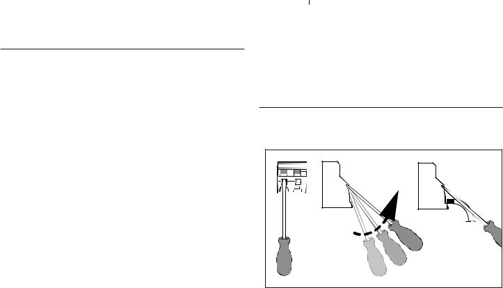
Electrical connections
Please refer to the pre-installation sheet for that concerning the i- dentification of the electric box terminal strip.
L2 |
-insert the flat head screwdriver in the hole indicated (the central one)
-lift the screwdriver so that the clamp is free and insert the conductor
-remove the screwdriver locking the conductor in the clamp; pull it lightly to check that it is properly blocked.
39
|
|
11 |
|
|
|
|
|
|
|
Flow |
|
|
|
|
9 |
10 |
|
|
|
Access Door |
|
|
|
|
|
|
|
|
|
|
6 |
1 |
|
|
|
|
|
|
|
|
|
|
8 |
4 |
|
3 |
|
|
7 |
|
|
|
|
2 |
6 |
Note: Pump Locations Vary by Model |
|
6 |
2 |
5 |
|
|
|
1 Electrical box
2 Power supply entrance(s)
3 Pump1
4 Heater
5 Drain valve
6 Pump drain plug(s)
7 Pump 2
8 Circulaiton pump
9 Ozonator
10Injector
11Display
Start-Up Instructions
Read each step in its entirety before proceeding with that step.
■Remove any dirt from the spa. Although the spa shell has been polished at the factory, you may want to treat it with a specially formulated spa cleaner and wax available from your dealer prior to filling the first time.
■Filling the Spa
Remove the filter cover, then remove both filter cartridges as outlined in section “Cleaning The Filters”.
Place the end of your garden hose into empty skimming filter bucket (filter bucket on your left) as you stand next to the spa. Fill spa half way, then place the garden hose into the opposite filter bucket (filter bucket on your right) while adding the remaining fill water.
Fill spa until water level is above all jets and just touching the bottom of each headrest in its lowest position.
Do not overfill your mini-pool.
N.B.: If your water is extremely hard, it is preferable to fill halfway with hard water and the rest of the way with softened water. Or, you may fill entirely with hard water if you use a special water additive.
Always fill the spa from both filter connections, so as to expel air trapped in the pumps. Otherwise the air may remain trapped, preventing the pumps from circulating the water.
After filling, make sure both filters are installed properly before applying power to the spa. (refer to sec. “Cleaning The Filters”).
■ Checks
Open the cabinet access panel and check all pump fittings to make sure they are tight. Loosening can occur during shipping and handling.
■ Turn on Power
Turn on power to spa from the main switch (refer to the chapter "Electrical safety". The heater and circulation pump will automatically activate.
The flashing of the water temperature icon together with "COOL" or "ICE" on the display of the control panel may be normal as the water in the system is often cold; please refer to the "Problem resolving - Display messages" section.
■ Startup
Start up the pumps (refer to "Control panel" chapter).
■ Addition of chemcial additives at first start-up
Add the spa water chemicals as recommended by your dealer (refer to the chapter “Water Quality Maintenance” for general guidance).
WARNING!
Do not get in the spa until the quantity of disinfectant has not dropped below the level recommended by the manufacturer and/or by your retailer.
■ Water heating
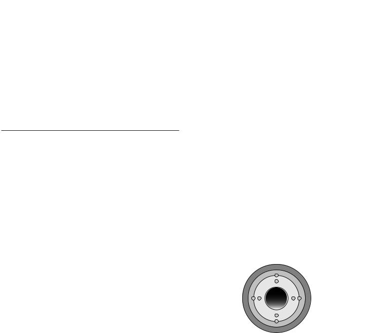
The water can be heated once the parameters of the chemical additives have reached the correct value: use the circular keypad to either increase or decrease the temperature.
up
left |
right |
down
■ The heater will be turned off when the temperature has exceeded the temperature set by 1 degree and will be reactivated when the temperature descends 1 degree below that set.
Heater characteristics:
-The maximum temperature that may be set is 40 °C, the minimum is 27 °C.
-If the spa is supplied according to the minimum electric current absorption configuration (see pre-installation sheet) turn the pump off to activate the heater.
-Setting the temperature at maximum only results in a higher end temperature and will not accelerate the heating process itself.
N.B.: Always cover the spa (except during the mixing of the chemical additives!) with an isolating cover thus reducing the heating times and minimising the running costs.
The time necessary for the initial heating varies based on the start temperature of the water.
Always check water temperature carefully before entering spa.
40

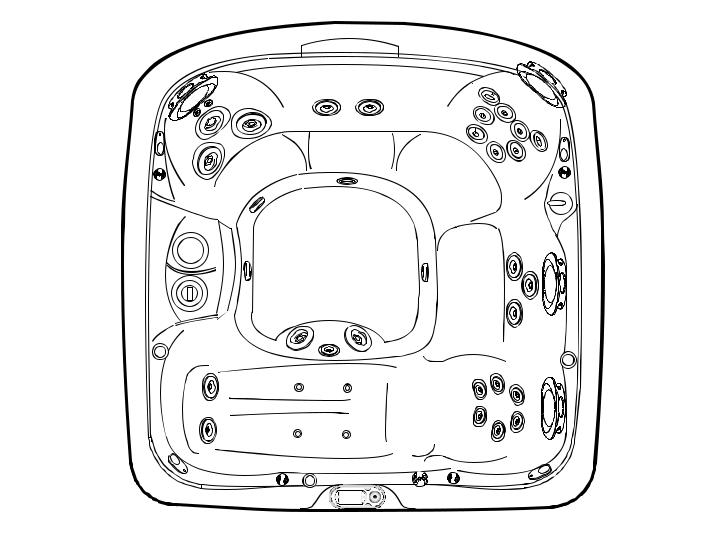
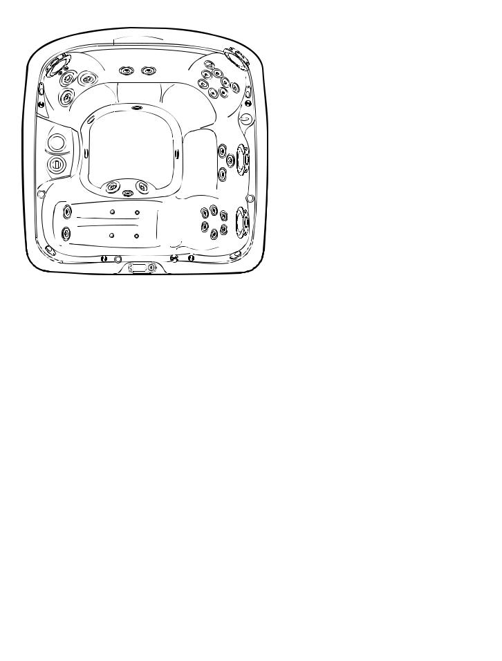
CHARACTERISTICS AND CONTROLS |
J-480 |
5 |
|
|
|
8 |
|
|
5 |
|
|
|
13 |
|
|
||
|
|
|
|
|
|
|
|
4 |
12 |
|
|
|
|
14 |
|
|
|
|
|
|
|
||
|
|
|
|
|
|
4 |
|
|
|
|
|
|
|
|
|
6 |
|
|
|
18 |
|
|
6 |
3 |
|
|
|
|
|
|
|
|
|
17 |
|
19 |
|
3 |
|
|
|
|
|
|
|||
11 |
17 |
20 |
|
20 |
|
|
|
|
|
|
17 |
|
|
||
10 |
|
|
20 |
21 |
20 |
|
|
|
|
|
|
|
|||
|
|
|
|
|
|
||
7 |
19 |
|
17 |
22 |
15 |
7 |
|
|
|
||||||
|
|
|
|
|
|
|
|
6 |
|
|
|
|
|
|
6 |
|
9 |
|
|
16 |
|
|
|
|
|
|
|
|
|
|
|
5 |
|
|
25 |
|
5 |
4 |
|
3 |
|
|
|
|
|
4 |
2 |
98F |
23 |
3 |
|
|
24 |
|
|
1 |
|
|
|
|
|
|
|
|
|
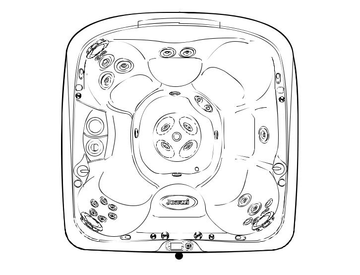
J-480
1.Control Panel
2.Waterfall Control Valve
3.Air Control Valve (4 ea.) Introduce Air to Specified Jet Groups
4.Optional Audio System Speaker (4 ea.)
5.Adjustable Pillows (4 ea.)
6.Cup Holder (4 ea.)
7.Massage Selectors (2 ea.) Controls Specified Jet Groups
8.Waterfalls (2 ea.)
9.FX Jets (4 ea.) And FX2 Jets (2 ea.)
10.ProClearTM Plus Polishing Filter Bag
11.ProClearTM Floating Skimmer And Filter Cartridge with Integrated Chemical Dispenser.
12.NX Jets (2 ea.) And MX2 Jets (3 ea.)
13.FX2 Jets (2 ea.)
14.NX Jets (2 ea.) And FX Jets (10 ea.)
15.Lounge Jets:
RX Back Jets (6 ea.),
SX2 Wrist And Calve Jets (6 ea.),
16.Lighted Seat Logo
17.Footwell Filter Suction Covers (3 ea.)
18.Waterfall Filtration Return
19.FX Calf Jets (4 ea.)
20.FX Footwell Jets (4 ea.)
21.IX suction jet (lighted)
22.Heater draining/inlet/ozone return joint.
23.Suction jet flow control valve (lighted)
24.Optional Audio System Receiver
25.Audio system infrared sensors (optional)
41

JET/AIR CONTROLS |
J-480 |
|
3 |
|
|
|
J-480 |
||
|
|
|
|
|
|||
|
|
|
|
|
|
|
Massage Selectors (1-2) |
|
|
|
|
|
|
||
|
|
|
|
|
|
|
• Massage selector 1 diverts pump 2 output |
|
5 |
|
|
|
between jets groups 1a-1b. |
||
|
|
2b |
|
• Massage selector 2 diverts pump 1 output |
|||
|
|
1b |
|
|
|||
|
|
|
|
|
between jet groups 2a-2b. |
||
|
|
|
|
|
|
|
|
|
|
|
|
2b |
|
Waterfall Selector (3) |
|
|
|
|
|
|
• Waterfall selector 3 controls circulation |
||
|
|
|
|
|
|
|
|
|
5 |
|
2a |
|
pump output to waterfalls. |
||
|
4 |
|
2a |
|
Massage Selector (4) |
||
|
|
|
|
|
|
|
|
|
|
|
|
|
|
|
• Massage selector 4 controls pump 1 out- |
|
5 |
|
|
|
put to footwell Jet. |
||
1 |
|
1a |
|
|
|
2 |
|
|
|
|
|
||||
|
|
|
|||||
|
|
|
|
|
|
|
Jets Without Massage Selector |
|
|
|
|
|
|
|
Controls (5) |
|
|
1a |
|
|
|
• Jets 5 are always on when jets pump 2 is |
|
|
|
|
2a |
|
running. |
||

 98F
98F 


34
|
|
|
J-480 |
|
|
|
Air Controls Operation |
|
|
|
|
|
|
|
|
|
|
|
• Rotate air controls 1-4 to add air to des- |
|
2 |
|
ignated jet groups. |
|
|
• The centre jets of well carry air continuous- |
|
|
|
3 |
|
2 |
|
ly when pump 1 is in operation. This jet is |
|
|
|
not equipped with an adjustment device.
2 |
|
|
|
|
3 |
3 |
4 |
|
|||
|
|
||||
|
2 |
|
|
||
|
|
|
|
||
|
|
|
4 |
|
|
|
2 |
|
|
|
|
|
1 |
|
|
|
|
|
4 |
4 |
|
|
|
|
1 |
4 |
|
|
|
|
|
|
|
|
|
98F |
14
42
CHARACTERISTICS AND CONTROLS |
J-470 |
|
|
|
8 |
|
|
|
5 |
|
|
|
5 |
|
|
|
13 |
|
|
|
|
12 |
|
|
14 |
4 |
|
|
|
|
|
|
|
|
|
4 |
|
|
|
|
|
|
|
6 |
|
|
18 |
|
6 |
3 |
|
17 |
|
19 |
3 |
|
|
|
|||
|
11 |
20 |
|
20 |
|
|
17 |
|
|
|
|
|
|
|
17 |
15 |
|
|
|
|
21 |
||
|
10 |
20 |
20 |
|
|
|
|
|
|||
|
|
|
|
||
7 |
|
|
17 |
22 |
7 |
|
|
|
|||
6 |
|
|
|
|
6 |
|
|
9 |
16 |
|
25 |
|
5 |
|
|
26 |
5 |
4 |
3 |
2 |
98F |
23 |
3 |
4 |
24 |
|
|
1 |
|
|
|
|
|
|
|
|
|
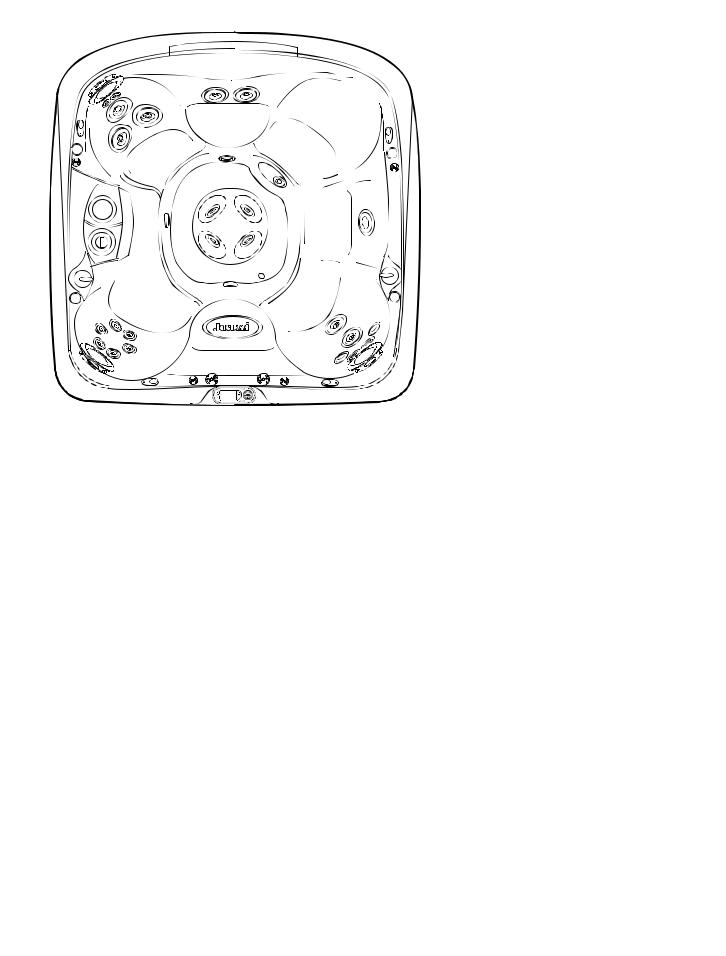
J-470 |
19. |
FX Calf Jets (2 ea.) |
|
|
|
20. |
FX Footwell Jets (4 ea.) |
1. |
Control Panel |
21. |
IX suction jet (lighted) |
2. |
Waterfall Control Valve |
22. |
Heater draining/inlet/ozone return joint. |
3. |
Air Control Valve (4 ea.) Introduce Air to Specified Jet |
23. |
Suction jet flow control valve (lighted) |
|
Groups |
24. Optional Audio System Receiver |
|
4. |
Optional Audio System Speaker (4 ea.) |
25. |
FX Jets (4 ea.) FX2 Jets (2 ea.) |
5. |
Adjustable Pillows (4 ea.) |
26. |
Audio system infrared sensors (optional) |
6.Cup Holder (4 ea.)
7.Massage Selectors (2 ea.) Controls Specified Jet Groups
8.Waterfalls (2 ea.)
9.RX Jets (6 ea.)
10.ProClearTM Plus Polishing Filter Bag
11.ProClearTM Floating Skimmer And Filter Cartridge with Integrated Chemical Dispenser.
12.NX Jets (2 ea.) And MX2 Jets (3 ea.)
13.FX2 Jets (2 ea.)
14.NX Jets (2 ea.) And FX Jets (10 ea.)
15.FX2 Jet
16.Lighted Seat Logo
17.Footwell Filter Suction Covers (4 ea.)
18.Waterfall Filtration Return
43
JET/AIR CONTROLS |
J-470 |
J-470
3
1b |
5 |
2b |
|
||
|
|
 2b
2b
5
 4
4  2a
2a
5
1 |
|
|
|
2 |
|
|
|||
|
Massage Selectors (1-2)
•Massage selector 1 diverts pump 2 output between jets groups 1a-1b.
•Massage selector 2 diverts pump 1 output between jet groups 2a-2b.
Waterfall Selector (3)
•Waterfall selector 3 controls circulation pump output to waterfalls.
Massage Selector (4)
•Massage selector 4 controls pump 1 output to footwell Jet.
|
|
Jets Without Massage Selector |
|
2a |
Controls (5) |
|
• Jets 5 are always on when jets pump 2 is |
|
|
|
|
1a |
|
running. |
98F |
34
|
|
|
|
|
|
|
J-470 |
|
|
|
|
|
|
|
Air Controls Operation |
|
|
|
|
|
|
|
• Rotate air controls 1-4 to add air to des- |
|
|
|
|
|
|
|
ignated jet groups. |
|
|
|
1 |
|
|
|
• The centre jets of well carry air continuous- |
|
2 |
3 |
|
|
ly when pump 1 is in operation. This jet is |
||
|
|
|
|
||||
|
|
|
|
|
not equipped with an adjustment device. |
||
|
|
|
|
|
|
|
|
2 |
|
|
1 |
3 |
|
|
3 |
|
|
|
|
||||
|
|
|
|
|
|||
|
|
|
|
|
|
|
|
|
|
|
|
|
4 |
|
|
|
|
|
1 |
|
|
|
|


 4
4 


 1
1 


 98F
98F 


14
44
CHARACTERISTICS AND CONTROLS |
J-465 |
|
|
8 |
|
5 |
5 |
|
|
|
|
13 |
14 |
|
|
|
|
|
13 |
||
|
|
|
|
|
4 |
17 |
9 |
|
|
|
|
4 |
||
|
|
|
||
|
|
|
|
|
3 |
|
|
|
3 |
|
12 |
20 |
|
7 |
|
12 |
|
|
|
|
|
|
|
|
11 |
|
|
|
|
|
12 |
12 |
|
5 |
10 |
|
14 |
||
|
|
|||
|
17 |
17 |
|
|
6 |
18 |
|
|
|
|
19 |
|
6 |
|
|
|
|
||
14 |
15 |
|
5 |
|
|
16 |
|||
|
|
|
|
|
4 |
|
|
23 |
|
|
|
|
|
|
4 |
|
2 |
6 |
|
21 |
3 |
|
98F |
|
||||
22 |
|
1 |
|
|
|
|
|
|
|
|
J-465 |
20. |
Waterfall Filtration Return |
|
|
|
21. Suction jet flow control valve (lighted) |
|
1. |
Control Panel |
22. |
Optional Audio System Receiver |
2. |
Waterfall Control Valve |
23. |
Audio system infrared sensors (optional) |
3.Air control valve (3) Carries air to specific groups of jets
4.Optional Audio System Speaker (4 ea.)
5.Adjustable Pillows (4 ea.)
6.Cup holder (3)
7.Massage selectors (1) control specific groups of jets
8.Cascade
9.FX Jets (10)
10.ProClearTM Plus Polishing Filter Bag
11.ProClearTM Floating Skimmer And Filter Cartridge with Integrated Chemical Dispenser.
12.Well Filter Suction Covers (4 ea.)
13.NX Jets (4)
14.FX2 Jets (7)
15.SX2 Jets (4)
16.RX Jets (6)
17.MX Jets (5)
18.IX suction jet (lighted)
19.Heater draining/inlet/ozone return joint.
45
JET/AIR CONTROLS |
J-465 |
|
|
|
|
|
|
|
|
J-465 |
|
3 |
Massage Selector (1) |
|
|
|
|
|
|
4 |
• Massage selector 1 diverts pump 1 output |
|
|
between jets groups 1a-1b. |
|
||
4 |
1a |
|
|
Massage Selector (2) |
|
||
• The massage selector 2 deviates the flow
exiting pump 1 to the well jet.
1
|
|
4 |
|
4 |
2 |
4 |
|
1b |
1b |
|
1b |
|
|||
|
|
|
|
Waterfall Selector (3)
•Waterfall selector 3 controls circulation pump output to waterfall.
Jets Without Massage Selector
Controls (4)
•Jets 4 are always on when jets pump 2 is running.
98F |
32
J-465
Air Controls Operation
• Rotate air controls 1-3 to add air to desi-
|
|
|
2 |
|
|
gnated jet groups. |
|
|
|
1 |
|
|
|
|
2 |
|
|
|
||
|
|
|
|
|
||
2 |
|
|
|
|
|
1 |
|
|
|
|
|
||
|
|
2 |
|
|
2 |
2 |
|
|
1 |
|
|
3 |
3 |
|
|
|
3 |
||
|
|
|
|

 98F
98F 


3
46
CHARACTERISTICS AND CONTROLS |
J-460 |
H
E  J
J 
 E
E
I
N
D


 D
D
C


 C
C
S G
P
Q
M
L N
 O
O  M
M
K
N
P
C 

 R P
R P  C
C
F
 F
F
D I J
I J  D
D
 I J
I J
I
 I I
I I
E
B


 T
T  E
E
A
 U
U
J-460 |
19. |
Suction jet flow control valve (lighted) |
|
20. |
Optional Audio System Receiver |
1. Control Panel |
21. Audio system infrared sensors (optional) |
|
2.Waterfall Control Valve
3.Air Control Valves (4 ea.) Introduce Air to Specified Jet Groups
4.Optional Audio System Speaker (4 ea.)
5.Adjustable Pillows (4 ea.)
6.Cup Holder (2 ea.)
7.Massage Selector (ea.) Controls Specified Jet Groups.
8.Waterfall
9.FX Jets (14 ea.)
10.FX2 Jets (5 ea.)
11.ProClearTM Plus Polishing Filter Bag
12.ProClearTM Floating Skimmer And Filter Cartridge with Integrated Chemical Dispenser.
13.SX2 Jets (4 ea.)
14.MX2 Jets (5 ea.)
15.IX suction jet (lighted)
16.Footwell Filter Suction Covers (4 ea.)
17.Heater draining/inlet/ozone return joint.
18.Waterfall Filtration Return
47
 Loading...