


J-355
Table of contents
 Loading...
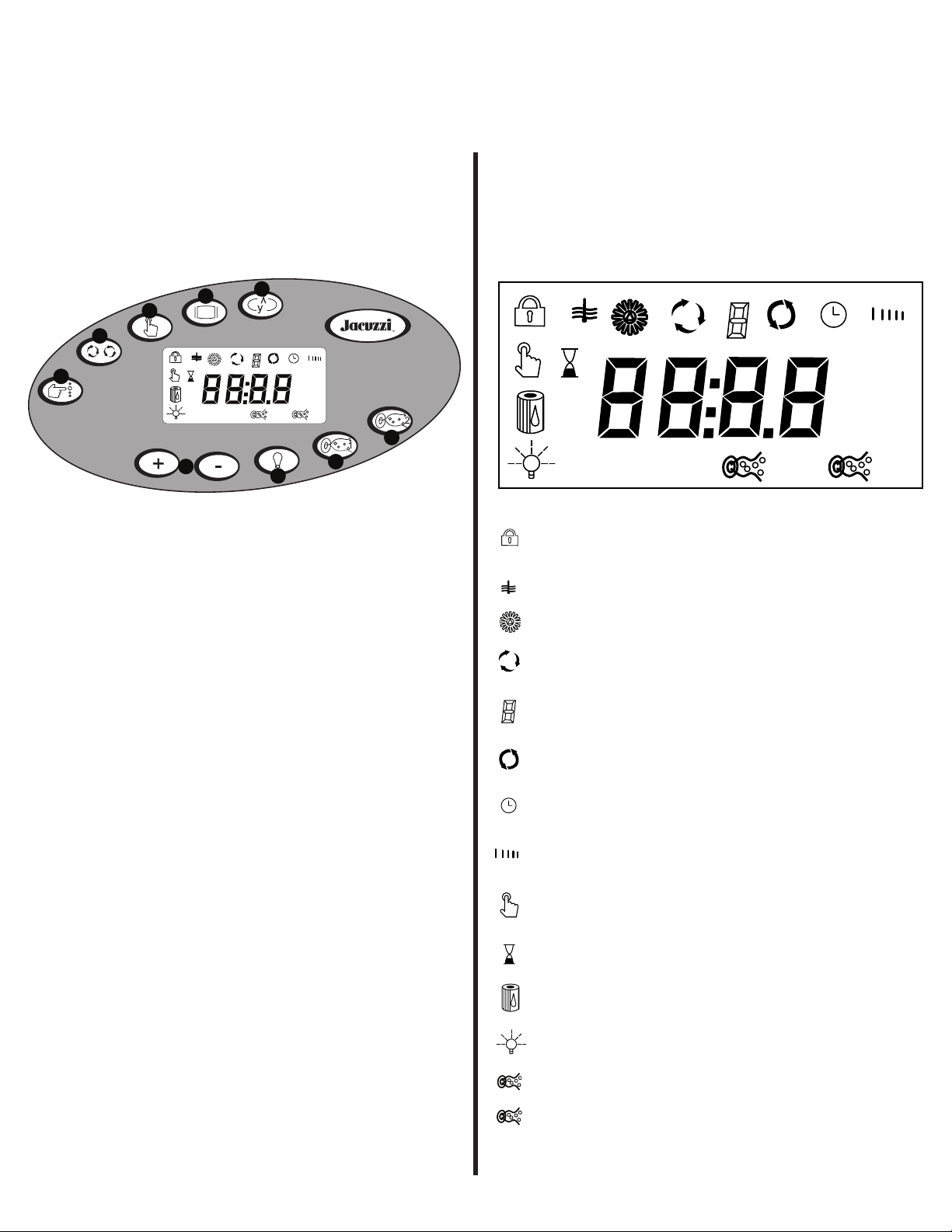
STANDA RD
AM
PM
A
B
C
D
E
G
H
I
F
ADDENDUM - Jacuzzi Hot Tubs
STAND A RD
AM
PM
STAND ARD
The control panel buttons and display symbols on some hot tubs has recently changed. This page replaces
sections 8.1 and 8.2 in specied owners manuals and has been provided to simplify setup and operation of
your new hot tub!
ADDENDUM:
This text replaces section 8.1 in all
Jacuzzi 300 LCD Series Owners manuals.
8.1 Control Panel
*Display shown for example purposes only, actual water
temperature will vary.
A. Select Button: Filter cycle programming features.
B. Cycle Button: Accesses filter cycle program mode
and next cycle.
C. Mode Button: Switches between standard and econ-
omy skimming/heating modes sections.
D. Display Button: Displays time of day and initiates time
setting and locking functions.
E. Invert Button: Inverts the main 4-digit LCD display.
ADDENDUM:
This text replaces section 8.2 in all
Jacuzzi 300 and 400 LCD Series Owners manuals.
8.2 Display Symbols
= Lock: Indicates panel, set temperature, or lter cycle
programming is locked.
= Heat: Indicates heater is on.
= Ozone: Indicates optional CD ozonator is on.
= Adjust Filter Cycle: Indicates lter cycle programming
feature is accessed.
= Filter Cycle Number: Indicates which
programmed lter cycle is running.
= Filter Cycle: Indicates programmed lter cycle is run-
ning.
F. Warmer (+) and Cooler (-) Buttons: These buttons
display, increase or decrease the temperature setting.
They also display other programmable features.
G. Light Button: Controls the spa light.
H. Jets 1 Button: Controls the 2-speed jets pump #1
(Low, High, Off).
I. Jets 2 Button: Controls jets pump 2&3 as follows:
• In J-355/J-365/J-375 Models: It controls high-speed
jets pump #2 (On, Off).
• In J-385 Models: It controls high-speed jets pump 2&3
(On, Off)
= Filter Cycle Start Time: Indicates lter cycle start time
programming is accessed.
= Filter Cycle Duration: Indicates lter cycle
duration programming is accessed.
= Set Temperature: Indicates the current set
temperature is displayed.
= Set Time: Indicates current time is displayed.
= Filter Annunicator: Indicates lter
cleaning and/or replacement.
= Light: Indicates light is on.
= Jets 1: Indicates jets pump 1 is on.
= Jets 2: Indicates jets pump 2 is on.
= Mode: Indicates selected lter mode. Note: No
icon means Economy mode is selected.
2530-249, Rev.A
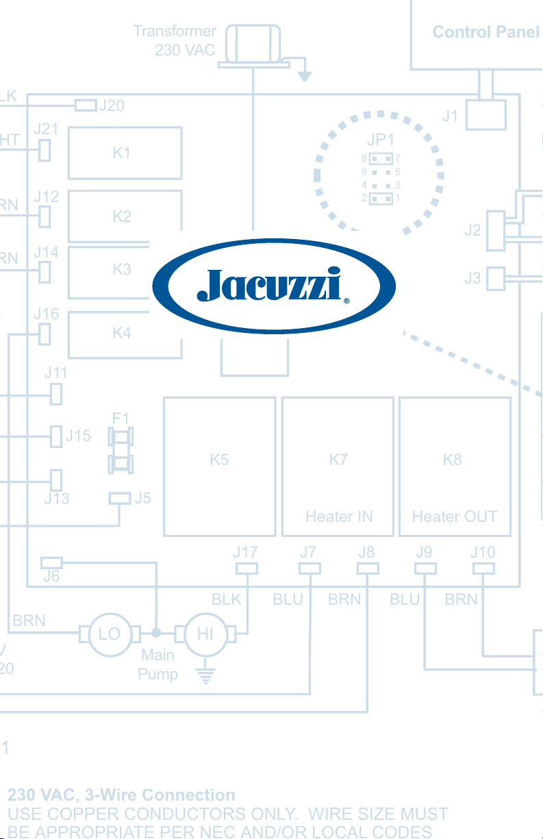
Transformer
230 VAC
Control Panel
J21
J12
J14
J16
J11
J13
J15
J20
K1
K2
K3
K4
F1
J5
J1
JP1
8 7
6 5
4
3
2
1
J4
K5 K7 K8
Heater IN Heater OUT
J2
J3
J17 J7 J8 J9 J10
J6
BLK BLU BRN BLU BRN
BRN
HILO
Main
Pump
LCD Series Hot Tub Owner’s Manual
J-355TM, J-365TM, J-375TM, J-385TM Models
6530-358, Rev. B
230 VAC, 3-Wire Connection
USE COPPER CONDUCTORS ONLY. WIRE SIZE MUST

Attention New Spa Owner!
pH 7.2 - 7.4
Free Chlorine 3-5 ppm
Free Bromine 4-6 ppm
Total Alkalinity 100-120 ppm
Calcium Hardness 150-250 ppm
Congratulations on the purchase of your new Jacuzzi® spa! The following is a list
of automated functions performed by your spa. These functions are listed below
in an attempt to suppress any operational concerns you may have during the rst
24-hours of ownership! Also listed below are important maintenance recommendations you should observe on a regular basis to protect your new investment.
Automated Operations
Your new spa is equipped with an automated “blow-out” cycle that clears all
plumbing lines daily to promote maximum water sanitation. Each day at 12:00 PM
(noon), pump 2 automatically turns on for a period of one minute, then goes off.
Then pump 1 will turn on and run for one minute to complete the blow-out cycle.
Be aware, the factory programmed blow-out cycle cannot be canceled or altered!
Maintain Healthy Spa Water
Always maintain your spa’s water chemistry within the following parameters as
dened by the Association of Pool And Spa Professionals/USA:
Always maintain your spas lter as outlined below to ensure healthy spa water.
Refer to page 39 “Water Quality Maintenance” for additional information.
Required Filter Maintenance
Your new spa is equipped with an advanced water ltration system that provides
unsurpassed water quality! To ensure maximum water quality at all times, you
should clean the lter cartridge every three months, or earlier as necessary. See
page 33-35 for detailed lter cartridge cleaning/replacement instructions.
Required Water Replacement
You should replace the spa’s water every 3 months. The frequency
depends on a number of variables including frequency of use, number of users,
and attention paid to water quality maintenance. You will know it is time for a
change when you cannot control sudsing and/or you can no longer get
feel or sparkle to the water, even though the key water balance measurements
are all within the proper parameters. See page 39 for additional information.
the normal

Table of Contents
1.0 Important Spa Owner Information .................................. 1
2.0 Important Safety Instructions .........................................
3.0 Choosing A Location .......................................................
3.1 Outdoor Location ...............................................................
3.2 Indoor Location ..................................................................
4.0 General Electrical Safety Instructions ........................... 9
5.0 Power Requirements .....................................................
6.0 Electrical Wiring Instructions .......................................
7.0 Spa Fill Up Procedure ...................................................
2
8
8
9
10
12
14
8.0 Control Functions ..........................................................
8.1 Control Panel ...................................................................
8.2 LCD Display .....................................................................
9.0 Spa Features And Controls ..........................................
9.1 Jet/Air Controls Diagram (J-385 & J-375) ........................
9.2 Jet/Air Controls Diagram (J-365 & J-355) ........................
10.0 Operating Instructions ..................................................
10.1 Set Spa to Heat ...............................................................
10.2 View ................................................................................. 24
10.3 Light ................................................................................. 24
10.4 Activate Pump 1 ...............................................................
10.5 Activate Pump 2/Pump 3 .................................................
10.6 Selecting Desired Massage Action ..................................
10.7 Adjusting Individual Jet Flow ...........................................
10.8 Adjusting PowerPro Jets ..................................................
10.9 Waterfall Feature .............................................................
10.10 Air Controls ......................................................................
10.11 Optional Jacuzzi Audio System .......................................
11.0 Automatic Filtration Cycles ..........................................
11.1 Standard Skimming/Heating Mode ..................................
11.2 Economy Skimming/Heating Mode ..................................
11.3 Selecting Standard/Economy Skimming/Heating Mode ..
11.4 Preset Skimming/Heating Cycles ....................................
11.5 Clean-Up Cycle ................................................................
19
19
20
21
22
23
24
24
25
25
26
26
26
26
26
27
27
27
28
28
28
29
12.0 Programming Instructions ............................................
12.1 Adjusting Time of Day ......................................................
12.2 Changing Skimming/Heating Cycles ...............................
29
29
29

12.3 Programming The Filter Change Reminder ..................... 30
12.4 Programming Circulation Pump Run Time ......................
12.5 Locking Skimming/Heating Cycles ..................................
12.6 Panel Lock .......................................................................
12.7 Temperature Setting Lock ................................................
31
32
32
32
13.0 Spa Maintenance ............................................................
13.1 Cleaning The Filters .........................................................
13.2 Draining and Refilling .......................................................
13.3 Cleaning The Spa Interior ................................................
13.4 Pillow Care .......................................................................
13.5 Maintaining The Cover .....................................................
13.6 Maintaining The Cabinet ..................................................
13.7 Winterizing ....................................................................... 38
13.8 Restarting Your Spa in Cold Weather ..............................
14.0 Water Quality Maintenance ...........................................
14.1 pH Control ........................................................................
14.2 Sanitizing .........................................................................39
14.3 Optional CD Ozone Water Maintenance System ............
14.4 Summer Logic ..................................................................
15.0 Troubleshooting - Display Messages ..........................
16.0 Troubleshooting - Procedures ......................................
17.0 Wiring Diagram (60Hz J-355/J-365/J-375 Models) ......
18.0 Wiring Diagram (60Hz J-385 Model) .............................
19.0 Wiring Diagram (50Hz J-355/J-365/J-375 Models) ......
20.0 Wiring Diagram (50Hz J-385 Model) .............................
21.0 Typical Spa Wiring Diagrams A-B (60Hz Models) .......
22.0 Optional Stereo Receiver - Features ............................
33
33
35
36
37
37
37
39
39
39
40
40
41
43
45
46
47
48
49
50

1.0 Important Spa Owner Information
Your Jacuzzi® spa is constructed to the highest standards and is capable of providing many years of trouble-free use. However, because heat
retentive materials are utilized to insulate the spa for efficient operation, an uncovered spa surface directly exposed to sunlight and high
temperatures for an extended period is subject to permanent damage.
Damage caused by exposing the spa to this abuse is not covered by
warranty. We recommend that you always keep the spa full of water
when it is exposed to direct sunlight and that you keep the Jacuzzi insulating cover in place at all times when the spa is not in use. Read and
carefully follow the requirements for your spa’s support base found in
the section 3.0 titled, “Choosing A Location” (page 8) or as prescribed
by your authorized Jacuzzi dealer.
Jacuzzi spas constantly strives to offer the finest spas available,
therefore, modifications and enhancements may be made which
affect the specifications, illustrations and/or instructions contained
herein.
FCC Notice
This equipment has been tested and found to comply with the limits for
a Class B Digital Device, pursuant to Part 15 of the FCC Rules. These
limits are designed to provide reasonable protection against harmful
interference in a residential installation. This equipment generates, uses
and can radiate radio frequency energy and, if not installed and used
in accordance with the instructions, may cause harmful interference to
radio communications. However, there is no guarantee that interference
will not occur in a particular installation. If this equipment does cause
harmful interference to radio or television reception, which can be determined by turning the equipment off and on, the user is encouraged to
try to correct the interference by one or more of the following measures:
1. Rearrange or relocate the receiving antenna;
2. Increase the separation between the equipment and receiver;
3. Connect the equipment into an outlet on a circuit different from the
circuit connected;
4. Consult the dealer or an experienced radio/TV technician for help.
(Changes or modifications not expressly approved by the party
responsible for FCC compliance could void the user’s authority to
operate this equipment.)
Page 1

2.0 IMPORTANT SAFETY INSTRUCTIONS
READ AND FOLLOW ALL INSTRUCTIONS CAREFULLY
When installing and using this electrical equipment, basic safety precautions should always be followed, including:
Warning: To reduce the risk of injury, do not permit children to use
1.
this product unless they are closely supervised at all times.
Warning: A grounding wire connector is provided on this unit to
2.
connect a minimum No. 8 AWG (8.4mm2) solid copper conductor between this unit and any metal equipment, metal enclosures
of electrical equipment, metal water pipe, or conduit within 5 feet
(1.5m) of the unit.
Danger: Risk of Accidental Drowning. Extreme caution must be
3.
exercised to prevent unauthorized access by children. To avoid
accidents, ensure that children cannot use this spa unless they are
supervised at all times.
Danger: Risk of Injury. The suction fittings in this spa are sized to
4.
match the specific water flow created by the pump. Should the need
arise to replace the suction fittings or the pump, be sure that the
flow rates are compatible. Never operate the spa if the suction fittings are broken or missing. Never replace a suction fitting with one
rated less than the flow rate marked on the original suction fitting.
Danger: Risk of Electric Shock. Install at least 5 feet (1.5m), from
5.
all metal surfaces. As an alternative, a spa may be installed within
5 feet of metal surfaces if each metal surface is permanently connected (bonded) by a minimum No. 8 AWG (8.4 mm2) solid copper
conductor attached to the wire connector on the grounding lug,
inside the equipment compartment on the equipment box.
Danger: Risk of Electric Shock. Do not permit any electrical appli-
6.
ance, such as a light, telephone, radio, television, etc. within 5 feet
(1.5m) of a spa unless such appliances are built-in by the manufac
turer.
Electrical Supply: The electrical supply for this product must
7.
include a suitably rated switch or circuit breaker to open all
ungrounded supply conductors to comply with section 422-20 of the
Page 2
-

National Electrical Code/USA, ANSI/NFPA 70. The disconnect must
be readily accessible and visible to the spa occupant but installed at
least 5 feet (1.5m), from the spa water.
8. Warning: To Reduce the Risk of Injury:
9. The water in the spa should never exceed 104°F (40°C). Water
temperatures between 100°F (38°C) and 104°F (40°C) are consid
ered safe for a healthy adult. Lower water temperatures are recommended for young children and when spa use may exceed 10 min
utes.
-
-
10. Since excessive water temperatures have a high potential for caus
ing fetal damage during the early months of pregnancy, pregnant or
possibly pregnant women should limit spa water temperatures to
100°F (38°C). If pregnant, please consult your physician before
using a spa.
11. Before entering the spa, the user should measure the water
temperature with an accurate thermometer since the tolerance of
water temperature-regulating devices may vary as much as +/- 5°F
(2°C).
12. The use of alcohol, drugs, or medication before or during spa use
may lead to unconsciousness with the possibility of drowning.
13. Persons suffering from obesity or a medical history of heart disease,
low or high blood pressure, circulatory system problems, diabetes,
infectious diseases or immune deficiency syndromes should consult
a physician before using a spa. If you experience breathing difficulties in association with using or operating your spa, discontinue
use and consult your physician.
14. Persons using medication should consult a physician before using
a spa since some medication may induce drowsiness, while other
medication may affect heart rate, blood pressure, and circulation.
-
15. Always shower before and after using your spa. To reduce the pos
sibility of contracting a waterborne illness, always maintain water
chemistry within the parameters listed on the inside cover of this
manual. If you or other bathers experience such a condition, discontinue use and seek medical attention.
Page 3
-

IMPORTANT CSA SAFETY INSTRUCTIONS (CANADA ONLY)
When using this electrical equipment, basic safety precautions should
always be followed, including the following:
Read and follow all instructions.
1.
2. A green colored terminal or a terminal marked G, Gr, Ground,
Grounding or the
box or compartment. To reduce the risk of electric shock, this
terminal must be connected to the grounding means provided in the
electric supply service panel with a continuous copper wire equivalent in size to the circuit conductors that supply this equipment.
*IEC Publication 417, Symbol 5019.
symbol* is located inside the supply terminal
3. At least two lugs marked “Bonding Lugs” are provided on the exter
nal surface or on the inside of the supply terminal box/compartment.
To reduce the risk of electric shock, connect the local common
bonding grid in the area of the spa to these terminals with an insulated or bare copper conductor not smaller than No. 6 AWG.
4. All field-installed metal components such as rails, ladders, drains
or other similar hardware within 10 feet (3m) of the spa shall be
bonded to the equipment grounding buss with copper conductors
not smaller than No. 6 AWG.
5. SAVE THESE INSTRUCTIONS.
WARNING: Children should not use spas without adult supervision.
WARNING: Do not use spas unless all suction guards are installed to
prevent body and hair entrapment.
WARNING: People with infectious diseases should not use a spa.
WARNING: To avoid injury, exercise care when entering or exiting the
spa.
WARNING: Do not use drugs or alcohol before or during the use of a
spa to avoid unconsciousness and possible drowning.
-
Page 4

WARNING: Pregnant or possibly pregnant women should consult a
physician before using a spa.
WARNING: Water temperature in excess of 40°C (104°F) may be injurious to your health.
WARNING: Before entering the spa, measure the water temperature
with an accurate thermometer.
WARNING: Do not use a spa immediately following strenuous
exercise.
WARNING: Prolonged immersion in a spa may be injurious to your
health.
WARNING: Do not permit electric appliances (such as lights, telephone,
radio, television, etc.) within 5 feet (1.5m) of this spa unless such
appliances are built-in by the manufacturer.
CAUTION: Maintain water chemistry in accordance with manufacturer’s
instructions.
WARNING: The use of alcohol or drugs can greatly increase the risk of
fatal hyperthermia in spas.
SAVE THESE INSTRUCTIONS
Page 5

HYPERTHERMIA
Prolonged immersion in hot water may induce hyperthermia. A description of the causes, symptoms, and effects of hyperthermia are as follows:
Hyperthermia occurs when the internal temperature of the body reaches
a level several degrees above the normal body temperature of 98.6°F
(37°C). The symptoms of hyperthermia include drowsiness, lethargy,
and an increase in the internal temperature of the body. The effects of
hyperthermia include:
1. Unawareness of impending hazard;
2. Failure to perceive heat;
3. Failure to recognize the need to exit spa;
4. Physical inability to exit spa;
5. Fetal damage in pregnant women; and
6. Unconsciousness and danger of drowning.
A warning sign is provided in your warranty packet. Please install
it at a location near your spa, where it is visible to the user of the
spa. For additional or replacement signs please contact your local
Jacuzzi Spas dealer and reference item number #6530-082.
CAUTIONS
1. Persons suffering from heart disease, diabetes, high or low blood
pressure, and any condition requiring medical treatment, pregnant
women, the elderly, or infants should consult with a physician before
using a spa.
2. The Consumer Products Safety Commission/USA has stated that
the water temperature in a spa should not exceed 104°F (40°C).
Immersion in water in excess of 104°F (40°C) can be hazardous to
your health.
Page 6

3. Observe a reasonable time limit when using the spa. Long exposures at higher temperatures can cause high body temperature.
Symptoms may include dizziness, nausea, fainting, drowsiness, and
reduced awareness. These effects could possibly result in drowning.
4. Do not use the spa under the influence of alcohol, narcotics, or
other drugs. Use of the spa under these conditions may lead to serious consequences.
5. Always test the spa water temperature before entering the spa.
Enter and exit the spa slowly. Wet surfaces can be very slippery.
6. Never bring any electrical appliances into or near the spa. Never
operate any electrical appliances from inside the spa or when you
are wet unless such appliances are built-in by the manufacturer.
7. Proper chemical maintenance of spa water is necessary to
maintain safe water and prevent possible damage to spa
components.
8. Use the straps and clip tie downs to secure the cover when not in
use. This will help to discourage unsupervised children from entering the spa and keep the spa cover secure in high-wind conditions.
There is no representation that the cover, clip tie-downs, or actual
locks will prevent access to the spa.
Page 7

3.0 Choosing A Location
IMPORTANT: Because of the combined weight of the spa, water and
users, it is extremely important that the base upon which the spa rests
be smooth, flat, level and capable of uniformly supporting this weight,
without shifting or settling, for the entire time the spa is in place. If the
spa is placed on a surface which does not meet these requirements,
damage to the skirt and/or the spa shell may result. Damage caused by
improper support is not covered under warranty. It is the responsibility of
the spa owner to assure the integrity of the support at all times.
We recommend a poured, reinforced concrete slab with a minimum
thickness of 4 inches (10cm). Wood decking is also acceptable provided
it is constructed so that it meets the requirements outlined above. The
spa must be installed in such a manner as to provide drainage away
from the spa. Placing the spa in a depression without provisions for
proper drainage could allow rain, overflow and other casual water to
flood the equipment and create a wet condition in which it would sit.
For spas which will be recessed into a floor or deck, install so as to
permit access to the equipment, either from above or below, for servicing. Make certain that there are no obstructions which would prevent
removal of the cabinet side panels and access to the jets components,
especially on the side with the equipment bay doors.
3.1 Outdoor Location
In selecting the ideal outdoor location for your spa, we suggest that you
take into consideration:
1. The proximity to changing area and shelter (especially in areas sub
ject to colder climates).
2. The pathway to and from your spa (this should be free of debris so
that dirt and leaves are not easily tracked into the spa).
3. The closeness to trees and shrubbery (remember that leaves and
birds could create extra work in keeping the spa clean).
4. A sheltered environment (less wind and weather exposure can
result in lowered operation and maintenance costs).
5. The overall enhancement of your environment. It is preferable not to
place the spa under an unguttered roof overhang since run-off water
will shorten the life expectancy of the spa cover.
Page 8
-
3.2 Indoor Location
For indoor installations, be certain to make provisions for proper ventilation. When the spa is in use, considerable amounts of moisture will
escape. This can damage certain surfaces over time. If you have any
questions regarding the placement or installation of your spa, consult
your authorized Jacuzzi dealer.
WARNING: In addition to maintenance of filters and water
chemistry, proper ventilation is recommended to reduce the
risk of exposure to viruses and bacteria that could be present
in the air or water. Consult a licensed architect or building
contractor to determine your specific needs if installing your
spa indoors.
4.0 General Electrical Safety Instructions
Your new Jacuzzi spa is equipped with a “state-of-the-art” equipment
system. It contains the most advanced safety and self-protective equipment in the industry. Nonetheless, this spa must be installed properly to
insure dependable usage. Please contact your dealer or local building
department should you have any questions regarding your installation.
Proper grounding is extremely important. Jacuzzi spas are equipped
with a current collector system. A pressure wire connector is provided
on the surface of the control box, located outside the equipment door
(Figure-B, page 13) to permit connection of a bonding wire between
this point and any ground metal equipment, metal water pipe or conduit
within 5 feet (1.5m) of the spa, or copper clad grounding rod buried
within 5 feet (1.5m) of the spa.
Bonding wire must be at least No. 8 AWG (8.4mm2) solid copper wire.
This is a most important safety assurance feature. Before installing this
spa, check with the local building department to insure installation conforms to local building codes.
Page 9

5.0 Power Requirements
Jacuzzi® spas are designed to provide optimum performance and flexibility of use when connected to the maximum electrical service as listed
in the tables below. If you prefer, your Jacuzzi dealer can perform a
minor circuit board modification to allow the spa to accept different electrical service. The operational considerations of these modifications are
listed in the footnotes below.
US/Canada J-355/J-365/J-375 Models (60Hz)
240V/50A* 240V/60A** 240V/40A***
Voltage: 240 VAC 240 VAC 240 VAC
Number of Wires: 3 3 3
Frequency: 60Hz 60Hz 60Hz
Current Draw: 36A 43A 26A
Circuit Breaker: 50A, 2-Pole 60A, 2-Pole 40A, 2-Pole
Important Information:
* In 50A configuration, the heater will not operate while both jets
pumps are running in high speed. This is the factory setting.
Note: Jets pump 2 runs only in high speed.
** In 60A configuration, the heater will operate while both jet pumps
are running in high speed. Note jets pump 2 runs only in high
speed.
*** In 40A configuration, the heater will not operate while either jets
pump is running in high speed. Note: jets pump 2 runs only in
high speed.
US/Canada J-385 Models (60Hz)
240V/60A* 240V/50A** 240V/40A***
Voltage: 240 VAC 240 VAC 240 VAC
Number of Wires: 3 3 3
Frequency: 60Hz 60Hz 60Hz
Current Draw: 46A 36A 31A
Circuit Breaker: 60A, 2-Pole 50A, 2-Pole 40A, 2-Pole
Important Information:
* In 60A configuration, the heater will operate while any two jets
pumps are running in high speed. This is the factory setting.
** In 50A configuration, the heater will not operate while any two
jets pumps are running in high speed. Note: jet pumps 2&3 run
only in high speed.
*** In 40A configuration, the heater will not operate while any jets
pump is running in high speed. Note: jet pumps 2&3 run only in
high speed.
Page 10
Export J-355/J-365/J-375 Models (50Hz)
230V/20A* 230V/30A** 230V/40A***
Voltage: 230 VAC 230 VAC 230 VAC
Number of Wires 3 3 3
Frequency: 50Hz 50Hz 50Hz
Current Draw: 15A 23A 29A
Circuit Breaker: 20A 30A 40A
Important Information:
* In 20A configuration, the heater will not operate while either jets
pump is running in high speed. Note: jets pump 2 runs only in high
speed. This is the factory setting.
** In 30A configuration, the heater will not operate when both jet
pumps are running in high speed. Note jets pump 2 runs only in
high speed.
*** In 40A configuration, the heater will operate while both jet pumps
are running in high speed.
All export models can be adapted to use higher amperage circuits when
available. Please contact your dealer for details. The electrical supply for
this product must comply with local electrical regulations.
Export J-385 Models (50Hz)
230V/35A* 230V/40A**
Voltage: 230 VAC 230 VAC
Number of Wires 3 3
Frequency: 50Hz 50Hz
Current Draw: 26A 32A
Circuit Breaker: 35A, 2-pole 40A, 2-pole
Important Information:
* In 35A configuration, the heater will not operate while any two
jet pumps are running in high speed. Note: Jet pump #2 and #3
run only in high speed.
** In 40A configuration, the heater will not operate while all three
jets pumps are running in high speed. Note: Jets pump 2 & 3
run only in high speed.
All export models can be adapted to use higher amperage circuits when
available. Please contact your dealer for details. The electrical supply
for this product must comply with local electrical regulations.
Page 11

6.0 Electrical Wiring Instructions
IMPORTANT NOTICE: The electrical wiring of this spa must
meet the requirements of the National Electrical Code/USA
(NEC) and any applicable state or local codes. The electrical
circuit must be installed by a qualified electrician and approved
by a local building/electrical inspection authority.
1. This spa must be permanently connected (hard-wired) to the power
supply. No plug-in connections or extension cords are to be
used in conjunction with the operation of this spa. Supplying
power to the spa which is not in accordance with these instructions
will void both the independent testing agency listing and the manufacturer’s warranty.
2. The power supplied to this spa
other appliances or lights sharing the power provided by the circuit.
3. To determine the current and voltage and wire size required, refer to
section 5.0 “Power Requirements” (page 10-11).
• Wire size must be appropriate per NEC and/or local codes.
• We recommend type THHN wire.
• All wiring must be copper to ensure proper connections.
aluminum wire.
• When using wire larger than #6 (10mm
the spa and reduce to short lengths of #6 (10mm
to spa.
4. The electrical supply for this product must include a suitably rated
switch or circuit breaker to open all ungrounded supply conductors
to comply with Section 422-20 of the National Electrical Code/USA,
ANSI/NFPA 70. The disconnecting means must be readily accessible to the spa’s occupant but installed at least 5 feet (1.5m) from
spa water.
5. The electrical circuit supplied for the spa must include a suitable
ground fault circuit interruptor (GFCI) as required by NEC Article
680-42.
6. To gain access to the spa’s power terminal block, remove the
screws securing the synthetic skirt panel under the control panel
(page 21). Then remove the four control box door screws and door
(Figure-B page 13).
7. Select the power supply inlet you want to use (Figure-A) and
remove the short cabinet panel from the front of the spa to allow
you to feed the cable through to the control box. Install the cable
with connector through the large opening provided in the bottom of
must be a dedicated circuit with no
Do not use
2
), add a junction box near
2
) wire to connect
Page 12

the control box.
Figure-B - Control Box
10
4
37
3
1
2
2
2
1. Terminal Block
2. Bonding Lug
3. Grounding Terminal
TB1
Figure-A
Equipment Area
1. Control Box
2. Power Supply Entrance(s)
3.
2-Speed Jets Pump #1
4. Heater
5. Spa Drain Valve
6. Pump Drain Plug(s)
7. 1-Speed Jets Pump #2
8.
Circulation Pump
9. Optional CD Ozonator (Purchased Separately)
10. Ozone Injector
1
Flow
Note: Pump Locations Vary by Model
Circulation Pump
Behind Load Box
8
5
6 6
9
8. Connect wires, color to color, on terminal blocks TB1 and TB3
(Figures C-D, page 14). TIGHTEN SECURELY! All wires must be
hooked up securely or damage could result.
9. Install control box door and screws and reinstall the cabinet side
panels.
Page 13
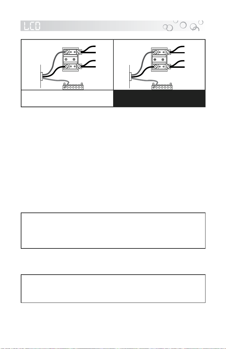
BLUE
BLUE
BROWN
BROWN
1
2
US/Canada J-355 / J-365 / J-375 / J-385
Models: 240 VAC, 3-Wire Connection (60Hz)
Figure-D
TB1
All Export J-355 / J-365 / J-375 / J-385
Models: 230 VAC, 3-Wire (50Hz)
to Circuit
Board
BLK
RED
Power In
RED
RED
BLK
BLK
1
2
Figure-C
TB1
to Circuit
Board
Power In
Figure-B - Control Box
Green
TB3
Green
TB3
10
4
37
3
1
2
2
2
1. Terminal Block
2. Bonding Lug
3. Grounding Terminal
TB1
Figure-A
Equipment Area
1. Control Box
2. Power Supply Entrance(s)
3.
2-Speed Jets Pump #1
4. Heater
5. Spa Drain Valve
6. Pump Drain Plug(s)
7. 1-Speed Jets Pump #2
8.
Circulation Pump
9. Optional CD Ozonator (Purchased Separately)
10. Ozone Injector
1
Flow
Note: Pump Locations Vary by Model
Circulation Pump
Behind Load Box
8
5
6 6
9
7.0 Spa Fill Up Procedure
FOR BEST RESULTS, read each step in its entirety before proceeding
with that step:
1. Prepare Spa For Filling
• Clear all debris from the spa. (Although the spa shell has been
• Remove filter lid then remove filter cartridge from filter bucket.
polished at the factory, you may want to treat it with a specially formulated spa cleaner. Consult your dealer for additional information
prior to filling spa.
2. Fill Spa
• Place the end of your garden hose into the empty filter bucket.
CAUTION: Never fill with water from a water softener. If your water is
extremely “hard”, it is preferable to fill half-way with hard water and the
rest of the way with softened water. Or, you may fill entirely with hard
water if you use a special water additive available from your authorized Jacuzzi dealer.
• Fill spa until water covers all jets but does not touch the bottom of
the lowest headrest. DO NOT OVERFILL.
IMPORTANT: Always fill your spa through the filter bucket after draining. Failure to do so may cause air to be trapped in either pump,
preventing the pump from circulating water. Remove the hose and
replace the filter cartridge.
Page 14

3. Turn On Power
Turn on power to spa at the home’s circuit breaker. The heater and
filter/circulation pump will automatically activate. If the control panel
LCD flashes water temperature and “COOL” or “ICE”, refer to section 15.0 (page 41-42) for additional information.
4. Activate Jets Pump 1
Depress the JETS 1 button on the control panel once to
activate jets pump #1.
5. Add Start-Up Chemicals
Add the spa water chemicals as recommended by your autho
rized Jacuzzi dealer. See section 14.0 “WATER QUALITY
MAINTENANCE” (page 39) for general guidance.
6. Establish A Stable Sanitizer Reading
Establish a stable sanitizer reading between 3 ppm and 5 ppm.
To ensure healthy water conditions, always maintain a constant
sanitizer reading within the levels recommended by the Association of Pool And Spa Professionals/USA printed on the inside cover
of this manual. If sanitizer levels cannot be stabilized, perform the
decontamination procedure steps 9-15 on page 16-18. Note: the
“decontamination procedure” steps 9-15 should also be used after
the spa has been “Winterized” (page 38) or has been sitting without
power for an extended period.
-
7. Set Spa To Heat
To warm spa water to a comfortable temperature, follow these
steps:
• The LCD display on the control panel displays the actual tem
perature of the spa water. Press either the COOLER (Down) or
WARMER (Up) button once to display the “set” temperature for 5
seconds. If you want the water to heat to a different temperature,
simply press COOLER (Down) or WARMER (Up) within 5 seconds.
The set temperature increases or decreases by one degree each
time one of these buttons is pressed.
• The heater will turn off when the temperature corresponding to the
thermostat setting is achieved.
Important Heater Details:
• The maximum temperature for which the spa can be set is
104°F (40°C) and the minimum is 80°F (27°C).
-
Page 15
• Setting the thermostat at maximum will not accelerate the heating
process. This will only result in a higher ultimate temperature.
• The heater operates until the water reaches the programmed “set
temperature”, then turns off. The heater will reactivate after the
water cools to approximately 1.5° below the “set temperature.”
8. Place Cover On Spa
• Keeping the insulating cover in place anytime the spa is not in use
will reduce the time required for heating, thereby minimizing operat
ing costs.
• The time required for initial heat-up will vary depending on the start
ing water temperature.
DANGER: Risk of injury, always check water temperature carefully before entering spa!
Decontamination Procedure (Steps 9-15)
Steps 9-15 below are only required when sanitizer levels are unstable
after performing steps 1-6 above. Disregard steps 9-15 below if sanitizer
levels remain stable at 3 ppm to 5 ppm after performing steps 1-6 above.
9. Add 2.5 ounces of sodium dichlor for every 100 gallons of water.
Refer to the table below for approximate water ll volume by model.
CAUTION: Never add chlorine tablets (trichlor) to your spa for
any reason! This chemical may damage components within
your spa and void the manufacturer warranty.
-
-
Water Fill Volume by Model
Spa Model Approximate Fill Volume
J355 ......................................363 US Gallons (1,374 Liters)
J365 ......................................374 US Gallons (1,416 Liters)
J375 ......................................480 US Gallons (1,817 Liters)
J385 ......................................550 US Gallons (2,082 Liters)
Page 16
Loading...