

Page 1

Conserver XL-E Series
DOOR TYPE DISHMACHINES
INSTALLATION & OPERATION MANUAL
FOR JACKSON MODEL(S):
CONSERVER XL-E
October 14, 2014
P/N 07610-003-92-84 D
Jackson WWS, Inc.
P.O. Box 1060, Hwy 25E
Barbourville, KY USA
1.888.800.5672
www.jacksonwws.com
Page 2

Page 3

MANUFACTURERS WARRANTY
ONE YEAR LIMITED PARTS & LABOR WARRANTY
ALL NEW JACKSON DISHWASHERS ARE WARRANTED TO THE ORIGINAL PURCHASER TO BE FREE FROM DEFECTS IN
MATERIAL OR WORKMANSHIP, UNDER NORMAL USE AND OPERATION FOR A PERIOD OF (1) ONE YEAR FROM DATE OF
PURCHASE, BUT IN NO EVENT TO EXCEED (18) EIGHTEEN MONTHS FROM DATE OF SHIPMENT FROM THE FACTORY.
Jackson WWS agrees under this warranty to repair or replace, at its discretion, any original part which fails under normal use due to faulty
material or workmanship during the warranty period, providing the equipment has been unaltered, and has been properly installed, maintained
and operated in accordance with applicable factory instruction manual furnished with the machine and failure is reported to the authorized
service agency within the warranty period. This includes the use of factory specied genuine replacement parts, purchased directly from a Jackson
authorized parts distributor or service agency. Use of generic replacement parts may create a hazard and void warranty certication.
The labor to repair or replace such failed part will be paid by Jackson WWS, within the continental United States, Hawaii and Canada, during the
warranty period provided a Jackson WWS authorized service agency, or those having prior authorization from the factory, performs the service.
Any repair work by persons other than Jackson WWS authorized service agency is the sole responsibility of the customer. Labor coverage is limited
to regular hourly rates; overtime premiums and emergency service charges will not be paid by Jackson WWS.
Accessory components not installed by the factory carry a (1) one year parts warranty only. Accessory components such as table limit switches,
pressure regulators, pre-rinse units, etc. that are shipped with the unit and installed at the site are included. Labor to repair or replace these
components is not covered by Jackson WWS.
This warranty is void if failure is a direct result from shipping, handling, re, water, accident, misuse, acts of God, attempted repair by authorized persons,
improper installation, if serial number has been removed or altered, or if unit is used for purpose other than originally intended.
TRAVEL LIMITATIONS
Jackson WWS limits warranty travel time to (2) two hours and mileage to (100) one hundred miles. Jackson WWS will not pay for travel time
and mileage that exceeds this, or any fees such as those for air or boat travel without prior authorization.
WARRANTY REGISTRATION
To register your product go to www.jacksonwws.com or call 1-888-800-5672. Failure to register your product will void the warranty.
REPLACEMENT PARTS WARRANTY
Jackson replacement parts are warranted for a period of 90 days from date of installation or 180 days from the date of shipment from the factory,
whichever occurs rst.
PRODUCT CHANGES AND UPDATES
Jackson WWS reserves the right to make changes in design and specication of any equipment as engineering or necessity requires.
THIS IS THE ENTIRE AND ONLY WARRANTY OF JACKSON WWS. JACKSON’S LIABILITY ON ANY CLAIM OF ANY KIND, IN-
CLUDING NEGLIGENCE, WITH RESPECT TO THE GOODS OR SERVICES COVERED HEREUNDER, SHALL IN NO CASE EXCEED
THE PRICE OF THE GOODS OR SERVICES OR PART THEREOF WHICH GIVES RISE TO THE CLAIM.
THERE ARE NO WARRANTIES, EXPRESSED OR IMPLIED, INCLUDING FOR FITNESS OR MERCHANTABILITY, THAT ARE NOT
SET FORTH HEREIN, OR THAT EXTEND BEYOND THE DURATION HEREOF. UNDER NO CIRCUMSTANCES WILL JACKSON
WWS BE LIABLE FOR ANY LOSS OR DAMAGE, DIRECT OR CONSEQUENTIAL, OR FOR THE DAMAGES IN THE NATURE OF
PENALTIES, ARISING OUT OF THE USE OR INABILITY TO USE ANY OF ITS PRODUCTS.
ITEMS NOT COVERED
THIS WARRANTY DOES NOT COVER CLEANING OR DELIMING OF THE UNIT OR ANY COMPONENT SUCH AS, BUT NOT
LIMITED TO, WASH ARMS, RINSE ARMS OR STRAINERS AT ANYTIME. NOR DOES IT COVER ADJUSTMENTS SUCH AS, BUT
NOT LIMITED TO TIMER CAMS, THERMOSTATS OR DOORS, BEYOND 30 DAYS FROM THE DATE OF INSTALLATION. IN
ADDITION, THE WARRANTY WILL ONLY COVER REPLACEMENT WEAR ITEMS SUCH AS CURTAINS, DRAIN BALLS, DOOR
GUIDES OR GASKETS DURING THE FIRST 30 DAYS AFTER INSTALLATION. ALSO, NOT COVERED ARE CONDITIONS CAUSED
BY THE USE OF INCORRECT (NON-COMMERICAL) GRADE DETERGENTS, INCORRECT WATER TEMPERATURE OR PRES-
SURE, OR HARD WATER CONDITIONS.
i
Page 4

REVISION HISTORY
Revision
Letter
A 01-06-14 MHH 8241 Release to production.
B
C 08-29-14 KAP N/A Updated part on pg. 27.
D 10-14-2014 KAP N/A
Revision
Date
08-18-14 KAP 8305 Removed pg 17, updated part on page 20.
Made By Applicable ECNs Details
Added 208 volt schematic on page 32.
Updated available electrical characteristics on pg. 4.
Updated Dimensions pg. 1
Updated part on pg. 29
ii
Page 5

NOMENCLATURE FOR THE MODELS COVERED IN THIS MANUAL
CONSERVER XL-E
Model:
Serial No.:
Installation Date:
Service Rep. Name:
Chemical sanitizing, single-rack, door type machine
Jackson WWS, INC provides technical support for all
of the dishmachines detailed in this manual. We strongly
recommend that you refer to this manual before making
a call to our technical support staff. Please have this
manual with you when you call so that our staff can refer
you, if necessary, to the proper page. Technical support is
not available on holidays. Contact technical support toll
free at 1-888-800-5672. Please remember that technical
support is available for service personnel only.
Phone Number:
iii
Page 6

TABLE OF CONTENTS
SPECIFICATIONS
Machine Dimensions ..................................................................................................................1
Table Dimensions .......................................................................................................................2
Operating Parameters ................................................................................................................3
Electrical Requirements .............................................................................................................4
INSTALLATION
Instructions .................................................................................................................................7
False Panel Instructions ...........................................................................................................10
Operating Instructions ..............................................................................................................11
Delime Instructions ...................................................................................................................13
MAINTENANCE
Preventative Maintenance ........................................................................................................14
Troubleshooting ........................................................................................................................15
Solenoid Valve Instructions ..................................................................................................... 17
PARTS
Control Box Components ..........................................................................................................18
Chemical Feeder Pump Components ...................................................................................... 20
Hood Assembly ........................................................................................................................ 21
Door Assembly ......................................................................................................................... 22
Wash Arm Assembly ................................................................................................................ 24
Wash Manifold Assembly ......................................................................................................... 25
Tub Assembly .......................................................................................................................... 26
Wash Sump Assembly ............................................................................................................. 27
Spillway Assembly ................................................................................................................... 28
Pump & Motor Assembly .......................................................................................................... 29
Frame Assembly ...................................................................................................................... 30
Miscellaneous .......................................................................................................................... 31
SCHEMATICS
Electrical Schematics .............................................................................................................. 32
iv
Page 7
29 1/2 (750.28mm)
ALL VERTICAL DIMENSIONS ARE
+/-
1
2" FROM FLOOR
1 (24.63 mm)
W
1 (24.63 mm)
1
3 1/4 (337.18 mm)
29 1/2 (750.28mm)
78 (1981.20 mm)
WITH DOORS
OPEN
W
65 (1649.52 mm)
13 (330.20 mm)
D
2 1/2 (62.57 mm)
29 1/2 (748.82 mm)
56 7/8 (1444.05 mm)
DET
S
AN
R
A
ALL VERTICAL DIMENSIONS ARE
+/-
1
2" FROM FLOOR
9 3/4 (247.65 mm)
13 1/4 (337.18 mm)
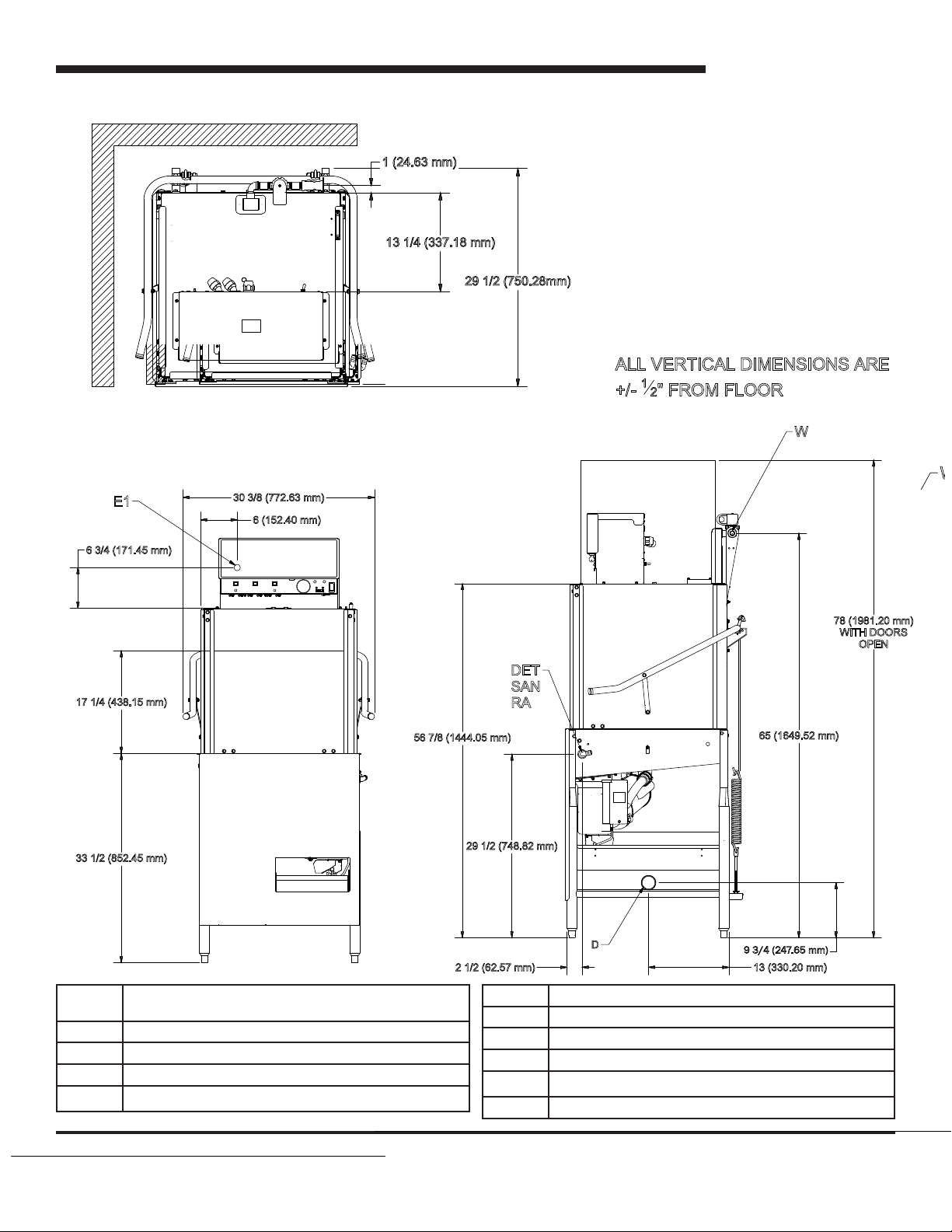
SPECIFICATIONS
MACHINE DIMENSIONS (Cons XL-E 115/60/1)
6 3/4 (171.45 mm)
17 1/4 (438.15 mm)
E1
30 3/8 (772.63 mm)
6 (152.40 mm)
56 7/8 (1444.05 mm)
29 1/2 (750.28mm)
DET
SAN
RA
ALL VERTICAL DIMENSIONS ARE
1
+/-
2" FROM FLOOR
65 (1649.52 mm)
W
78 (1981.20 mm)
WITH DOORS
OPEN
33 1/2 (852.45 mm)
E1 MAIN ELECTRICAL CONNECTION (1.125” DIA HOLE)
(Located on back of control box)
W MAIN INLET WATER CONNECTION (½ NPT-F)
D DRAIN CONNECTION (2” NPT-F)
DET DETERGENT BULKHEAD ACCESS (.875” DIA HOLE)
SAN** SANITIZER INLET
29 1/2 (748.82 mm)
2 1/2 (62.57 mm)
RA RINSE AND INLET
CP N/A
S* N/A
C* N/A
VI N/A
V2 N/A
1
D
9 3/4 (247.65 mm)
13 (330.20 mm)
Page 8
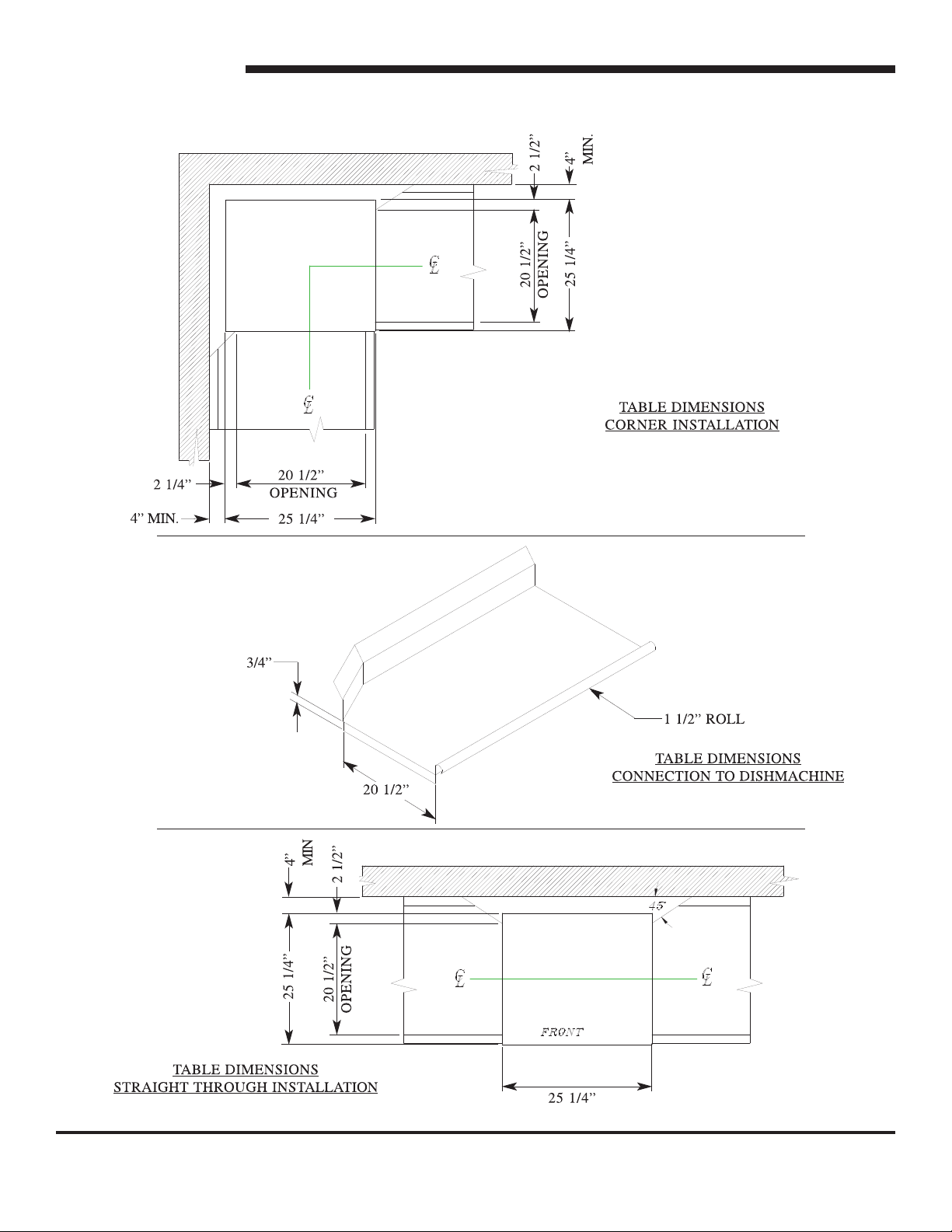
SPECIFICATIONS
TABLE DIMENSIONS
2
Page 9

Model Designation: CONS XL-E
Operating Capacity:
Racks per Hour 39
Dishes per Hour 624
Glasses per Hour 1404
Tank Capacity (Gallons):
Wash Tank 1.44 (90 GPH)
Electrical Loads (as applicable):
Wash Motor HP 3/4
SPECIFICATIONS
OPERATING PARAMETERS
NOTE: Always refer to the machine data plate for specic electrical and water requirements.
The material provided on this page is for reference only and is subject to change without notice.
CHEMICAL SANITIZING
Water Temperatures (Fahrenheit/Celsius):
Minimum Wash Temperature 120/49
Minimum Rinse Temperature 120/49
Incoming Water Temperature 120/49
Other Water Requirements:
Water Flow Pressure (PSI) 15
Flow Rate Minimum (GPM) 1.03
Water Line Size (NPT) 1/2”
Drain Line Size (NPT) 2”
Minimum Chlorine Required (PPM) 50
3
Page 10

SPECIFICATIONS
ELECTRICAL REQUIREMENTS
CONS XL-E
Wash
Volts Phase Freq
115 1 60 11.4 N/A N/A 11.4 14.3 25.7
Note 1: MCA (Minimum Circuit Ampacity) = 125% x Largest Motor + FLA of all other motors + all other loads.
Note 2: MOP (Maximum Overcurrent Protective Device) = 225% x Largest Motor + FLA of all other motors + all other loads.
Note 3: All electrical ratings provided in this manual are for reference only. Always refer to the machine data plate to get the
exact electrical information for your machine. All electrical work performed on machines should be done in accordance with
applicable local, state, territorial and national codes. Work should only be performed by qualied electricians and authorized
service agents. A list of authorized service agencies is located in the back of this manual.
Note that all electrical wiring used in the dishmachine must be rated, at a minimum, for 100°C (212°F). Furthermore, use
copper conductors only.
Where applicable, heating element amperage draws have been adjusted for the assumed input voltage. Jackson assumes
incoming voltages will be either 115, 208, 230 or 460 volts. Some of the heating elements used in our machines are actually
rated for other voltages, such as 240 or 480 volts. Always verify the amperage draw of the machine in operation when sizing
circuit protection.
Motor
Amps
Drive
Motor
Amps
Wash
Heater
Pumps
FLA MCA MOP
The electrical congurations of the machines are as follows:
Available Electrical Characteristics:
• 115 volt, 60 Hz, single phase
• 115 volt, 50 Hz, single phase
• 230 volt, 60 Hz, single phase
• 220 volt, 60 Hz, single phase
4
Page 11

INSTALLATION
INSTRUCTIONS
VISUAL INSPECTION: Before installing the unit, check the container and the machine for damage. A damaged container
may be an indication there is possible damage to the product. If there is any type of damage to both the container and the unit,
DO NOT THROW AWAY THE CONTAINER. The dishmachine has been previously inspected at the factory and is expected
to arrive to you in new, undamaged condition. However, rough handling by carriers or others may result in damage to the unit
while it is in transit. If such a situation occurs, DO NOT RETURN THE UNIT TO THE MANUFACTURER. Instead, contact the
carrier and ask them to send a representative to the site to inspect the damage. You should request that an inspection report be
completed. You must contact the carrier within 48 hours of receiving the machine in order to report possible freight damage. You
are also encouraged to contact the dealer through which you purchased the unit.
UNPACKING THE MACHINE: The machine should be unboxed and removed from the pallet prior to installing. Open the front
door and remove all of the materials from the inside. Once unpacked, verify there are no missing parts. If you discover a part is
missing, contact Jackson immediately.
LEVEL THE DISHMACHINE: The dishmachine is designed to operate while level. This is important to prevent any damage
to the machine during operation and to ensure the best results possible. The unit comes equipped with adjustable bullet feet,
which can be turned using a pair of pliers. Verify the unit is level from front to back and side to side prior to making any electrical
or plumbing connections.
PLUMBING THE MACHINE: All plumbing connections must be made to adhere to local, state, territorial and national codes.
The installing plumber is responsible for ensuring the incoming water lines are ushed of debris prior to connecting to the
machine. Note that chips and materials from cutting processes can become lodged in the solenoid valves and prevent them
from opening or closing. Any valves that are found to be fouled or defective because of foreign matter left in the water line, and
any subsequent water damage, are not the responsibility of the manufacturer.
Water hardness should be a maximum of 6 grains per gallon. Hard water should be treated prior to being used by the machine.
Iron in the water line can cause staining. A lter designed to remove iron from the water supply is highly recommended for
supplies in excess of 0.1 ppm.
The water supply line shall be ½” NPT minimum and must be able to provide water at the minimum temperature indicated on
the machine data plate.
The unit utilizes a ow pressure of 15 PSI for the incoming water line. Do not confuse static pressure with ow pressure. Static
pressure is the pressure present when there is no ow and the valves are closed; ow pressure is present when the water is
running into the machine. In areas where pressure uctuates or is greater than the recommended pressure, it is suggested that
a water pressure regulator valve be installed.
It is recommended that a shut-off valve be installed to allow isolating the dishmachine from the water system in the event that
maintenance or other activities are required. Also, it is suggested that a shock absorber (not supplied with dishmachine) be
installed on the incoming water line. This prevents water hammer (hydraulic shock)—induced by the solenoid valve as it
operates—from causing damage to the equipment.
CONNECTING THE DRAIN LINE: The drain for the unit is a gravity discharge drain. All piping to the machine drain must be a
minimum 2” NPT AND SHALL NOT BE REDUCED. There must also be an air gap between the machine drain line and the oor
sink or drain. If a grease trap is required by code, it should have a ow capacity of 5 gallons.
5
Page 12

INSTALLATION
INSTRUCTIONS
ELECTRICAL POWER CONNECTIONS: All electrical connections are to be made in accordance with applicable portions
of local, state, territorial and national codes.
DISCONNECT ELECTRICAL POWER SUPPLIES AND TAG OUT IN ACCORDANCE WITH APPROPRIATE PROCEDURES
AND CODES AT THE DISCONNECT SWITCH TO INDICATE YOU ARE WORKING ON THAT CIRCUIT.
This manual provides reference information regarding electrical requirements and loads, but that information may change
without notice. Always refer to the machine data plate for voltage requirements, machine voltage, total amperage load and
serial number. If you cannot read your data plate because it has been damaged, you should contact the manufacturer.
The main power terminal blocks (for the dishmachine and for the rinse booster heater, if applicable) are located at the top
of the machine. You will have to remove the top cover to access these connections. Route incoming power lines within
conduit that will connect via ttings to the pre-punched holes in the back of the Control Box. Install power and ground
wires to lugs as indicated by the appropriate decals in the control box. Use copper conductors only. Use of an anti-oxidation
agent is permissible on the power connections. Tighten all connections.
Verify the incoming voltage matches the voltage indicated on the decal next to the incoming power pre-punched hole.
DISHMACHINE VENTILATION: The dishmachine should be located into an adequate exhaust hood or ventilation system
with provisions for venting. This is essential to permit efcient removal of the condensation exhaust. Ensure the exhaust
system is acceptable in accordance with applicable codes and standards.
Note: Any damage that is caused by steam and/or moisture due to improper ventilation is NOT covered under the warranty.
The dishmachine has the following ventilation requirements: 200 CFM
The exhaust system must be sized to handle this volume for the dishmachine to operate in the manner it was designed.
THERMOSTATS: The thermostats on your unit have been set at the factory for the wash tank. They should only be
adjusted by an authorized service agent.
TO PREPARE CHEMICAL PUMPS FOR OPERATION: The Conserver XL-E dishmachine is supplied with detergent,
rinse additive and sanitizer-dispensing chemical feeder pumps. Locate the open ends of the chemical tubes with the tube
stiffeners and place each one in the appropriate container.
A. Red Tubing = Detergent B. Blue Tubing = Rinse Aid C. White Tubing = Sanitizer
PRIMING CHEMICAL FEEDER PUMPS: Chemical feeder pumps need priming when the machine is rst installed or if
the chemical lines have been removed and air is allowed to enter.
6
Page 13

INSTALLATION
INSTRUCTIONS
CAUTION: Water must be in the sump and wash tank prior to the dispensing of chemicals. Sanitizer in concentration
is caustic and may cause damage without dilution.
1. Verify that the proper chemical tube stiffener inlet is in the proper container.
2. Use the toggle switches on the front of the control box to prime each pump. There are 3 switches mounted by the peristaltic
pumps. One will prime the sanitizer pump only, the second will prime the detergent and the third will prime the rinse aid pump.
3. To prime the pumps, hold the switch in the momentary position until the chemical can be observed entering the sump.
4. Detergent is dispensed as required by the timer during the wash cycle. The amount of detergent may need to be
increased or decreased depending on water quality and type of detergent.
5. Rinse additive is dispensed as required into the nal rinse. The amount of rinse aid may need to be adjusted
depending on water hardness and results.
6. Sanitizer is dispensed into the nal rinse. The amount of sanitizer may need to be adjusted depending on the
concentration and type of sanitizer used.
7. Please refer to the next page for instruction on adjusting the chemical feeder pumps on the CAM timer.
WARNING: Some of the chemicals used in dishwashing may cause chemical burns if they come in contact with
your skin. Wear protective gear when handling these chemicals. If you do come in contact with these chemicals,
immediately ush the affected area with fresh water. Always refer to the chemical agent packaging for safe
handling and rst-aid instructions.
7
Page 14

INSTALLATION
CAM TIMER OPERATION
The Conserver XL-E Series CAM timer is a 1 minute, 30 second, 8-CAM timer (CAM 8 is a spare) that controls the operation of
the dishmachine. The following is a description of the set points for each CAM and the function of each switch.
CAM 1 is a cut CAM with a single notch that serves as the cycle/reset control.
FUNCTION: When the machine is in the operation mode the notch is in the home position. The machine will remain idle
until the door is opened, then CAM 1 moves to the start position and holds until the door is closed. The closing of the door
will start the next cycle. The CAM will rotate a complete cycle and return to the home position and hold.
CAM 2 is a cut CAM that provides the wash cycle timing.
FUNCTION: The wash CAM works off the normally open contacts of CAM 2. This requires the microswitch be held closed
by the CAM. It will close and energize the wash pump 2 seconds after the cycle switch is activated. The pump will operate
through the wash cycle (40 seconds) then shut down for the dwell period (20 seconds). As the CAM rotates it energizes
the pump for the rinse cycle (25 seconds). When CAM 1 reaches its home position it will de-energize CAM 2, shutting
down the wash pump.
NOTE: The last 6 CAMS are adjustable. The following instructions will require that the timer position have the
CAMs to the front and the motor to the left.
CAM 3 is an adjustable CAM that controls the drain valve.
FUNCTION: The drain solenoid works off the normally closed contacts of CAM 3. When the cycle is initiated, the microswitch
will be held open until it is allowed to drop into the notch of the CAM. This energizes the drain solenoid which then drains
the machine. After a 12 second delay the CAM reverses the microswitch, de-energizing the drain solenoid. This CAM may
require adjusting due to varying water pressure. The drain solenoid must remain open long enough to remove whatever
water the ll valve solenoid allows in the machine. This could vary due to the water supply line pressure.
SETTINGS: The right side of CAM 3 must be set to pick up the microswitch just before the wash/rinse cycle CAM switch
drops. It will hold the drain solenoid open to drain all the water in the tank from the unit during the dwell period. Any adjustment
made to the drain should be made to the left side of CAM 3. The CAM must be moved back into the wash time until all of
the water is drained from the machine.
CAM 4 is an adjustable CAM that controls the ll valve and the amount of water used.
FUNCTION: The ll valve CAM works off the normally closed contacts of CAM 4. This requires the microswitch to be held
open by the CAM and allowed to drop into the notch to operate the ll valve. This energizes the ll solenoid which opens to start
lling the machine with fresh water. After a 10 second delay the CAM reverses the microswitch, de-energizing the ll solenoid.
The ll CAM may require adjustment due to varying water pressure. The ll solenoid must remain open a sufcient length
of time to ll the machine to the correct level.
SETTINGS: The right side of CAM 4 must be set to allow the microswitch to drop 2 seconds before the drain solenoid
is de-energized to ensure the detergent residue is ushed from the unit. It will hold the ll solenoid open until the CAM
switch arm is raised. At that time the ll solenoid is de-energized, shutting off the incoming water. The tub will be lled to
the correct level. Any adjustment made to the timing of the ll solenoid should be made with the left side of CAM 4. To
increase the water level, open the notch of the CAM; to decrease, the notch should be closed.
8
Page 15

INSTALLATION
INSTRUCTIONS
CAM 5 is an adjustable CAM that controls the sanitizer pump.
FUNCTION: The sanitizer pump CAM works off the naturally closed contacts of CAM 5. This requires the microswitch to
be held open by the CAM and allowed to drop into the notch to operate the pump. The time that the sanitizer pump will
remain energized must be determined in the eld to suit water conditions and the chemical used.
SETTINGS: The left side of CAM 5 must be set to allow the microswitch to drop in past the starting point of the ll CAM
and after the drain solenoid has closed. The adjustment for sanitizer volume must be made with the right side of the CAM.
To increase the volume the notch should be increased. To decrease, the notch should be closed slightly in increments until
the correct level is reached.
CAM 6 is an adjustable CAM that controls the detergent pump.
FUNCTION: The detergent pump CAM works off the normally closed contacts of CAM 6. This requires the microswitch to
be held open by the CAM and allowed to drop into the notch to operate the pump. The time that the detergent pump will
remain energized must be determined in the eld to suit water conditions and the chemical used.
SETTINGS: The left side of CAM 6 must be set to drop in past the starting point of the wash pump CAM. The adjustment
for detergent volume must be made with the right side of the CAM. To increase the volume, the notch should be increased.
To decrease, the notch should be closed slightly in increments until the correct level is reached.
CAM 7 is an adjustable CAM that controls the rinse aid pump.
FUNCTION: The rinse aid pump CAM works off the normally closed contacts of CAM 7. This requires the microswitch to
be held open by the CAM and allowed to drop into the notch to operate the pump. The time that the rinse aid pump will
remain energized must be determined in the eld to suit water conditions and the chemical used.
SETTINGS: The left side of CAM 7 must be set to drop in past the starting point of the ll CAM after the drain solenoid
has closed. The adjustment for rinse aid volume must be made with the right side of the CAM. To increase the volume
the notch should be increased. To decrease, the notch should be closed slightly in increments until the correct level is
reached.
CAM 8 is a spare.
9
Page 16

INSTALLATION
FALSE PANEL INSTRUCTIONS
False Panel Weldment
05700-002-51-66
False Panel Kit
05700-003-12-93
Rack rail removed and repositioned
for a corner operation
False panel positioned in unit
Insert this side rst
1. Loosen the rack assembly from the unit.
2. False panel will mount to the rack inside the
dishmachine.
3. Position panel in unit on side to be closed.
4. Hold panel against side of dishmachine and push up.
5. Panel will clip inside the unit under the edge of the hood.
6. Holes in false panel will line up with rack assembly
holes.
7. Re-install screws for rack assembly which will secure
false panel to unit.
8. Re-assemble the rack track in an “L” shape for a
corner operation.
Bottom of side panel
10
Page 17

INSTALLATION
OPERATING INSTRUCTIONS
PREPARATION: Before proceeding with the start-up of the unit, verify the following:
• The sump strainer is in place and is clean.
• The drain stopper is installed.
• The strainers are installed.
POWER UP: To place the unit in standby, press the START button on the front of the machine.
FILLING THE WASH TUB: For the initial ll, close doors and depress and hold the OFF/ON/FILL rocker switch in the
FILL position for approximately 8-10 seconds. Open the doors and verify that the water level is correct. Water must be
between two lines on drain stopper pipe. Hereafter, the water level is controlled by the timer that has been preset at the
factory. Verify that the drain stopper is preventing the wash tub water from pouring out excessively. There may be some
slight leakage from the drain hole. Verify that there are no other leaks on the unit before proceeding any further. The wash
tub must be completely lled before operating the wash pump to prevent damage to the component. Once the wash tub is
lled, the unit is ready for operation.
The water level is controlled by the timer that has been preset at the factory.
To increase or decrease the water level, close the door and turn the power circuit breaker on. Open and close the door to
run a cycle, then check the water level. Adjust as necessary and close the control box cover. The machine runs a complete
cycle to drain and ll. If the machine is not allowed to drain, the water will build up inside the tub. After the initial ll, the
rinse water for the current cycle will become the wash water for the next cycle.
FIRST RACK: The rst rack of ware that you place into the unit usually has the effect of very quickly reducing the
temperature of the wash tank. This is because you are introducing cold materials into the dishmachine environment and
the unit has to circulate water to activate the heating cycle. You may have to run the rst rack through the unit again. Any
time the unit has not been operated for an extended period of time this is possible, but unlikely. This is usually dependent
on the type of ware you are using, its temperature and the ambient temperature of the kitchen area. To ensure proper
operation, always observe the temperatures of the wash and rinse when rst starting the unit.
WARE PREPARATION: Proper preparation of ware is essential for the smooth, efcient operation of your dishmachine.
If done properly, you can expect to have fewer re-washes and use substantially less detergent. Any ware placed inside
the machine should have all solid food waste and scraps removed. It is recommended that ware also be sprayed down
prior to entry into the dishmachine.
Place cups and glasses upside down in racks so they do not hold water during the cycle. Presoak atware in warm water
to assist in removing food. Load plates and saucers in the same direction, with the food surface facing the unload end of
the machine.
11
Page 18

INSTALLATION
OPERATING INSTRUCTIONS
WASHING A RACK OF WARE: To wash a rack, open the doors completely (beware of hot water dripping from the doors)
and slide the rack into the unit. Close the doors and the unit will start automatically. Once the cycle is completed, open the
door (again careful of the dripping hot water) and remove the rack of clean ware. Replace with a rack of soiled ware and
close the doors. The process will then repeat itself.
OPERATIONAL INSPECTIONS: Based upon usage, the pan strainer may become clogged with soil and debris as the
workday progresses. Operators should regularly inspect the pan strainer to ensure it has not become clogged. If the
strainer becomes clogged, it will reduce the washing capability of the machine. Instruct operators to clean out the pan
strainer at regular intervals or as required by work load.
SHUTDOWN AND CLEANING: At the end of the workday, close the doors. When the unit completes the cycle, turn the
power switch to the OFF position and open the doors. Manually remove the drain stopper from the tub and allow the tub
to drain (CAUTION: Wash tank water will be hot!). Once the wash tub is drained, remove the pan strainer and the pump
suction strainer. Remove soil and debris from the strainer and set to the side. Unscrew the wash and rinse arms from
their manifolds. Remove the endcaps and ush the arms with water. Use a brush to clean out the inside of the arms. If the
nozzles appear to be clogged, use a toothpick to remove the obstruction. Wipe the inside of the unit out, removing all soil
and scraps. Reassemble the wash and rinse arms and replace them in the unit. The arms only need to be hand tight, do
not use tools to tighten them down. Reinstall the strainers and close the doors.
12
Page 19

INSTALLATION
DELIME INSTRUCTIONS
To proceed with the delime operation, ll the dishmachine with the correct amount of delime solution as recommended by the
manufacturer of the chemicals. The tank capacities of the machine can be found in the Specications section of this manual.
After the chemicals are added, perform the following steps:
1. Flip the NORMAL/DELIME Toggle Switch to DELIME. (NOTE: The Delime Swich is located on the
back of the control box)
2. Disconnect or turn off chemical feeder pumps.
3. Close all doors.
4. Press the Power Switch and run the machine for the length of time required by the chemical
solution manufacturer.
5. Press the Power Switch to shut the unit off.
6. Open the door and step away for 5 minutes.
7. Inspect the inside of the unit to determine if your expectations have been met. If not, you may need
to run the delime solution through the unit for more time.
8. Once clean, drain the machine completely.
9. Close the door.
10. Rell the unit.
11. Press the Power Switch and run the unit in Manual for 10 minutes.
12. Press the Power Switch to turn off the unit.
13. Open the front door.
14. Drain the unit.
15. Flip the NORMAL/DELIME Switch to NORMAL.
16. Your machine is ready to use.
This equipment is not recommended for use with deionized water or other aggressive uids.
Use of deionized water or other aggressive uids will result in corrosion and failure of materials and
components. Use of deionized water or other aggressive uids will void the manufacturer’s warranty.
13
Page 20

MAINTENANCE
PREVENTATIVE MAINTENANCE
The dishmachine covered in this manual is designed to operate with a minimum of interaction with the operator. However,
this does not mean that some items will not wear out in time. Jackson highly recommends that any maintenance and repairs
not specically discussed in this manual should be performed by QUALIFIED SERVICE PERSONNEL ONLY. Performing
maintenance on your dishmachine may void your warranty if it is still in effect.
There are many things that operators can do to prevent catastrophic damage to the dishmachine. One of the major causes
of component failure involves pre-scrapping procedures. A dishmachine is not a garbage disposal; any large pieces of material
that are put into the machine shall remain in the machine until they are either broken up (after spreading out on your ware!) or
physically removed. Strainers are installed to help catch debris, but they do no good if they are clogged. Have operators regularly
inspect the pan strainers to ensure (1) that they are free of soil and debris and (2) they are laying at in the tub.
When cleaning out strainers, do NOT beat them on waste cans. The strainers are made of metal but once severe damage
is done, it will not work properly. Wipe out strainers with a rag and rinse under a faucet if necessary. For stubborn debris, a
toothpick can be used to dislodge any obstructions from the perforations. Always ensure that strainers are placed back in the
machine before operation and that they lay at in the tub.
Refer to the section titled "Plumbing the Machine" (page 5) to learn more about how your water hardness will effect the
performance of your machine. Hard water makes dishmachines work harder and decreases efciency.
Again, it is important to remind operators that attempting corrective maintenance on the dishmachine could lead to larger
problems or even cause harm to the operator. If a problem is discovered, secure the dishmachine using proper shut down
procedures as listed in this manual and contact a QUALIFIED SERVICE AGENCY.
Some problems may not begin with the machine. One common problem occurs when temperatures are too low. Verify that
the water temperatures coming to your dishmachine match the requirements listed on the machine data plate. There can be a
variety of reasons why your water temperature is too low and you should discuss it with a QUALIFIED SERVICE AGENCY to
determine what can be done.
By following the operating and cleaning instructions in this manual, you should get the most efcient results from your machine.
As a reminder, here are some steps to ensure that you are using the dishmachine the way it was designed to work:
1. Ensure that the water temperatures match those listed on the machine data plate.
2. Ensure that all strainers are in place before operating the machine.
3. Ensure that all wash and/or rinse arms are secure in the machine before operating.
4. Ensure that drains are closed/sealed before operating.
5. Remove as much soil as possible from dishes before loading into racks.
6. Do not overll racks.
7. Ensure that glasses are placed upside down in the rack.
8. Ensure that all chemicals being injected into machine have been veried as being at the correct concentrations.
9. Clean out the machine at the end of every workday as per the instructions in the manual.
10. Always contact a QUALIFIED SERVICE AGENCY whenever a serious problem arises.
11. Follow all safety procedures, whether listed in this manual or put forth by local, state or national codes/regulations.
14
Page 21

PROBLEM POSSIBLE CAUSE REMEDY
Dishmachine will not run,
no voltage at wash relay
terminals L1 and T1.
1. Service disconnect switch
off or faulty.
2. Branch circuit breaker
tripped/fuse blown.
1. Turn disconnect on.
2. Reset or replace.
MAINTENANCE
TROUBLESHOOTING
Machine will not run in “ON”
position or in
Delime mode.
Machine lls continuously
even with no power
applied to the machine.
Dishmachine runs
continuously in the
wash cycle.
3. Loose or broken connection
to dishmachine.
1. Door switch is defective.
2. Faulty OFF/ON/FILL switch.
3. Faulty NORMAL/DELIME
switch.
Water inlet solenoid valve
allowing water into machine.
1. Machine is in Delime mode.
2. Possible issue with CAM timer.
3. Tighten or replace connections.
1. With door open, check for voltage between
ORANGE/WHITE door switch and neutral.
If 120V, replace the door switch.
2. With switch ON, check voltage between BLACK
and WHITE/BLACK ON switch. Replace the
switch if 120V.
3. In the NORMAL position, check the voltage between
WHITE/BLACK and WHITE/RED wires to switch.
If 120V, replace the switch.
1. Check water pressure during ll, pressure must
be 15 psi.
2. Repair or replace water inlet solenoid valve.
(See instructions on servicing solenoid valve, pg. 17.)
1. Flip NORMAL/DELIME switch to NORMAL mode.
2. Contact Jackson Technical Service.
Dishmachine will not
hold water.
Dishmachine will not ll, other
functions work.
1. Faulty drain ball.
2. Obstructed drain hole.
3. Drain linkage is binding.
1. Y-strainer clogged.
2. Incoming water to unit is
turned off.
3. Faulty OFF/ON/FILL switch.
4. Faulty solenoid coil.
15
1. Replace drain ball.
2. Clear obstruction from drain.
3. Repair damaged drain mechanism parts.
1. Clean strainer screen.
2. Turn on water to the machine.
3. Depress switch, measure between BLACK and
WHITE/GREEN wire. If 120V, replace switch.
4. If coil has voltage but no continuity, replace solenoid.
Page 22

MAINTENANCE
TROUBLESHOOTING
PROBLEM POSSIBLE CAUSE REMEDY
Dishmachine lls slowly and/
or the rinse is weak.
1. Clogged or obstructed
rinse arms.
1. Remove and clean the rinse arms.
2. Low incoming water pressure.
3. Y-strainer is clogged.
Doors will not close
completely.
Water leaks at wash pump. 1. Wash pump seal is defective.
Dishes are not coming clean. 1. Machine temperatures are not
1. Improper spring tension.
2. Obstruction in door channel.
2. Petcock or pump drain leaking.
up to the minimum requirements.
2. No detergent/too much
detergent.
2. Adjust the water pressure regulator to ensure that
there is 15 psi water ow pressure.
3. Clean out the Y-strainer.
1. Adjust spring tension as required by loosening
(not removing) spring bolt nuts and adjusting the
tension. Tighten nuts when done.
2. Remove the obstruction.
1. Replace wash pump seal.
2. Close shut or tighten.
1. Verify that incoming water temperature meets
requirements listed on the machine data plate.
2. Adjust detergent concentration as required for the
amount of water held by the machine. (It is
recommended the chemical provider be contacted
before making any changes.)
16
Page 23

PARTS
CONTROL BOX COMPONENTS
4
11
5
2
1
3
9
10
4
19
8
7
20
21
20
9 9
12
14
13
15
16
17
18
30
31
29
22
23
25
26
28
17
27
24
Page 24

PARTS
CONTROL BOX COMPONENTS
ITEM QTY DESCRIPTION PART NUMBER
1 1 Control Box Assembly 05700-003-81-49
2 1 Decal, Warning–Disconnect Power 09905-100-75-93
3 1 Upper Decal, Cons XL-E 09905-004-00-07
4 2 Peri Pump, 36 RPM 05700-003-25-02
5 1 Peri Pump, 14 RPM 05700-003-25-03
7 18 Lock Nut, 10-24 S/S Hex w/Nylon Insert 05310-373-01-00
8 1 Decal, Copper Conductors 09905-011-47-35
9 3 Light, Red 05945-504-07-18
10 1 Light, Green 05954-504-08-18
11 3 Switch, Prime 05930-011-49-54
12 6 Screw, 6-32 x ⅜ w/Washer 05305-002-25-91
13 6 P Clamp 05975-002-61-42
14 11 Lock Nut, 6-32 Hex w/Nylon Insert 05310-373-03-00
15 1 Gauge, Thermometer 06685-111-68-49
16 1 Cycle Counter, 115V 05990-111-35-38
17 2 Screw, 4-40 x ¼ Phillips Pan Head w/Washer 05305-002-32-38
18 1 Switch, Power 05930-111-38-79
19 1 Timer, Cons XL-E 90S 115V 05945-004-11-78
20 2 Chemical Feeder Pump Kit Assembly, 36 RPM w/Motor 05700-003-25-02
21 1 Chemical Feeder Pump Kit Assembly, 14 RPM w/Motor 05700-003-25-03
22 1 Lug, Ground 05940-200-76-00
23 1 Decal, Power Connection 09905-011-47-64
24 1 Terminal Block 05940-500-09-61
25 1 Terminal Board 05940-021-94-85
26 1 Contactor, 115V, 30A 05945-109-05-69
27 1 Bushing, Heyco Split 05975-200-40-00
28 2 Fitting, ½”, 45 degree, Plastic 05975-011-45-23
29 1 Fitting, ½", Plastic 05975-011-45-13
30 1 Relay, Pole 05945-111-35-19
31 1 Switch, Delime 05930-301-21-18
1 Lock, Control Box (NOT SHOWN) 05340-102-01-00
18
Page 25

PARTS
PARTS SECTION
Technical Manual (07610-003-92-84)
CHEMICAL FEEDER PUMP COMPONENTS
CHEMICAL FEEDER PUMP COMPONENTS
Chemical Feeder Pump Kit Assembly, 36 RPM
Chemical Feeder Pump Kit Assembly, 36 RPM w/
w/Motor 120V (Complete) 05700-003-25-02
Motor 120V (Complete) 05700-003-25-02
Chemical Feeder Pump Kit Assembly, 14 RPM w/
Chemical Feeder Pump Kit Assembly, 14 RPM
Motor 120V (Complete) 05700-003-25-03
w/Motor 120V (Complete) 05700-003-25-03
Front Housing
Front Housing
04320-111-37-08
04320-111-37-08
Screw, 6-32 x ¾”
Screw, 6-32 x 3/4”
Phillips Pan Head
Phillips Pan Head
4 per
4 per
05305-011-37-05
05305-011-37-05
Squeeze Tube, Detergent/Sanitizer
Roller, Red (Detergent/Sanitizer)
Roller, Red (Detergent/Sanitizer)
04320-111-36-70
04320-111-36-70
Roller, White (Rinse Aid)
Roller, White (Rinse Aid)
04320-002-82-28
04320-002-82-28
If using Tygoprene Tubing:
If using Tygoprene Tubing:
Roller, White
04320-002-82-28
Roller, White
Roller, Black
04320-002-82-28
04320-111-65-27
Roller, Black
04320-111-65-27
Screw, 8-32 x ⅜”
Screw, 8-32 x 3/8”
Phillips Pan Head
Phillips Pan Head
2 per
2 per
05305-011-37-07
05305-011-37-07
Screw, 8-32 x ½”
Screw, 8-32 x 1/2” Phillips
Flat Head
Phillips Flat Head
2 per
2 per
05305-011-37-06
05305-011-37-06
Squeeze Tube, Detergent/Sanitizer
(Use with the red roller.)
(use with the red roller)
05700-111-35-29
05700-111-35-29
Clear Squeeze Tube, Rinse Aid
Clear Squeeze Tube, Rinse Aid
(Use with the white roller.)
05700-011-76-41
05700-011-76-41
Tube, 3/16 x 8” Clear Tygoprene
Tube, 3/16 x 8” Clear Tygoprene
05700-003-22-89
05700-003-22-89
Rear Housing
Rear Housing
04320-111-37-09
04320-111-37-09
Motor, 14 RPM 115V
Motor, 14 RPM 115V
Rinse Aid Feeder Pump
Rinse Aid Feeder Pump
04320-111-35-13
04320-111-35-13
Motor, 14 RPM 240V
Motor, 14 RPM 240V
Rinse Aid Feeder Pump
Rinse Aid Feeder Pump
04320-111-47-46
04320-111-47-46
Motor, 36 RPM 115V
Motor, 36 RPM 115V
Detergent/Sanitizer Feeder Pump
Detergent/Sanitizer Feeder Pump
04320-111-35-14
04320-111-35-14
Motor, 36 RPM 240V
Motor, 36 RPM 240V
Detergent/Sanitizer Feeder Pump
Detergent/Sanitizer Feeder Pump
04320-111-47-47
04320-111-47-47
19
Page 26

PARTS
HOOD ASSEMBLY
13
12
14
1
2
3
15
6
11
10
9
8
7
5
4
ITEM QTY DESCRIPTION PART NUMBER
1 1 Control Box Assembly 05700-004-01-65
2 1 Hood, Weldment 05700-003-22-05
3 10 Lock Nut, ¼-20” w/Nylon Insert 05310-374-01-00
4 2 Hood Support 05700c-002-78-99
5 6 Bolt, ¼-20 x ½” 05305-274-02-00
6 12 Washer, S/S ¼” 05311-174-01-00
7 2 Bracket, Cantilever Support 09515-003-15-64
8 6 Wear Button 05700-011-88-01
9 1 Bracket, Plumbing Support 05700-003-24-25
10 1 Strainer, Inlet ½” 04730-217-01-10
11 2 Nipple, ½” x 2” (Brass) 04730-207-19-00
12 1 Solenoid Valve, ½”, 120V 04810-003-71-55
13 1 Elbow, ½” Street (Brass) 04730-206-08-00
14 1 Air Gap Weldment 05700-002-81-70
15 1 Gasket, Air Gap 05330-002-14-48
20
Page 27

PARTS
DOOR ASSEMBLY
3
23, 18
24, 18
10, 11, 12
13
20
2
1
9
15, 16
14
17, 18
4
5
6
7
8
22
3c
21, 25
3e
19, 11, 12
3d
3a
3b
21
Page 28

PARTS
DOOR ASSEMBLY
ITEM QTY DESCRIPTION PART NUMBER
1 1 Arm, Cantilever 05700-003-52-91
2 2 Spring Pin, ¼” Dia. x 1-⅛” 05315-407-06-00
3 2 Yoke Assembly 05700-000-75-77
3a 1 Cotter Pin 05315-207-01-00
3b 1 Yoke 05700-000-75-78
3c 1 Clevis Pin 05315-700-01-00
3d 2 Nylon Washer 05311-369-03-00
3e 1 Bushing 03120-100-03-00
3f 2 Lock Nut, ⅜”-16 S/S (not shown) 05310-256-04-00
4 2 Rod, Spring Universal 05700-003-67-39
5 2 Spring, Cantilever 05340-109-02-00
6 2 Bolt, Hanger Eye ⅜-16” 05306-956-05-00
7 2 Washer, ⅜” I.D. x ⅞” O.D. 05311-176-02-00
8 4 Nut, Hex ⅜-16” S/S 05310-276-01-00
9 2 Cantilever Arm Connector 05700-011-90-99
10 2 Screw, ¼-20” 05305-274-23-00
11 2 Washer, ¼” I.D. S/S 05311-174-01-00
12 2 Lock Nut, ¼-20” S/S w/Nylon Insert 05310-374-02-00
13 2 Sleeve, Cantilever Arm 05700-000-85-69
14 2 Plug, Cantilever 05340-011-35-00
15 1 Door Magnet 05930-111-51-68
16 2 Lock Nut, 8-32 S/S w/Nylon Insert 05310-272-02-00
17 1 Door Assembly, Right Side 05700-002-30-88
18 6 Door Guides 05700-111-33-59
19 10 Bolt, ¼-20” x ½” S/S 05305-274-02-00
20 2 Spacer, PB Bolt 05700-000-29-40
21 8 Lock Nut, ¼-20” w/Nylon Insert 05310-374-01-00
22 2 Bracket, Door Connecting 05700-021-33-39
23 1 Front Door Assembly 05700-002-30-89
24 1 Door Assembly, Left Side 05700-002-30-87
22
Page 29

Wash Arm Assembly
05700-021-87-76
PARTS
WASH ARM ASSEMBLY
ITEM QTY DESCRIPTION PART NUMBER
1 2 Bearing 05700-021-35-97
2 1 Wash Arm 05700-021-63-42
1 Wash Arm w/End Caps 05700-003-57-70
3 1 O-Ring. 117-S70 Silicon 05330-002-60-69
4 2 Wash Arm End Caps 05700-011-35-92
23
Page 30

PARTS
WASH MANIFOLD ASSEMBLY
1
2
9
10
9
3
4
5
6
7
8
3
4
ITEM QTY DESCRIPTION PART NUMBER
1 2 Bolt, ⅜-16 x ⅞" S/S 05306-011-36-95
2 1 Casting, Upper Wash Manifold 05700-031-34-82
3 4 ⅜" Lockwasher, S/S 05311-276-01-00
4 4 ⅜" Hex Nut, S/S 05310-276-01-00
5 2 Bolt, ⅜-16 x 1-¼" S/S 05305-276-10-00
6 1 Lower Wash Manifold 05700-003-78-40
7 1 Gasket, Wash Manifold 05700-111-35-03
8 2 ⅜" Bevel, Square 05311-011-35-03
9 2 O-Ring 05330-111-35-15
10 1 Wash Manifold Tube 05700-003-58-89
24
Page 31

PARTS
TUB ASSEMBLY
6
5
2
7
8
4
1
3
ITEM QTY DESCRIPTION PART NUMBER
1 1 Tub Assembly 05700-003-78-35
2 1 Rack Guide Assembly 05700-031-36-76
3 1 Bulkhead Fitting, ½” 04730-011-45-21
4
1
1
5 1 Wash Arm Assembly 05700-021-87-76
4
6
4
4
7
4
Clamp, Nylon
Lock Nut, 10-24 S/S
Bolt, ¼-20 x ½” S/S
Lock Nut, ¼-20 S/S
Bolt, ¼-20 x 1-⅛” S/S
Lock Nut, ¼-20 S/S
04730-011-39-01
05310-373-01-00
05305-274-02-00
05310-374-01-00
05305-274-21-00
05310-374-01-00
8 1 Lower Wash Manifold 05700-003-78-40
25
Page 32

PARTS
WASH SUMP ASSEMBLY
4
1
6
5
7
3
2
ITEM QTY DESCRIPTION PART NUMBER
1 1 Pump and Motor Assembly (see page 29) 06105-002-69-78
2 1 Pump Drain Hose 05700-003-78-58
3 2 Clamp, 7/16” to 25/32” 04730-011-36-05
4 1 Clamp, 5-⅝” to 6”, #96 04730-011-34-90
5 1 Sump Weldment 05700-003-78-41
6 1 Sump Gasket 05330-003-78-31
7 9 Lock Nut, ¼-20 S/S 05310-374-01-00
1 Drain Solenoid, 115V (NOT SHOWN) 04810-200-11-00
1 Drain Link Connector (NOT SHOWN) 05700-002-38-10
26
Page 33

Drain, Seat
05700-021-34-38
Spillway Weldment
05700-003-52-13
PARTS
SPILLWAY ASSEMBLY
Gasket, Spillway
05700-111-34-52
Drain Link
05700-003-78-49
Lock Nut, ¼-20 S/S
05310-374-01-00
Connection, Drain Link
05700-002-38-10
27
Page 34

PARTS
PUMP & MOTOR ASSEMBLY
Complete Pump and Motor Assembly
06105-002-69-78
Impeller
05700-002-81-86
Mechanical Seal
05330-002-34-22
Case Cap Screw
05305-002-81-88
Motor Only
06105-002-79-61
Seal Plate
05700-002-81-87
Case O-Ring
05330-002-81-83
Shim Kit
05700-002-82-58
Pump Dishcharge Hose
(not shown)
05700-003-78-50
Hose Clamp, 1-5/16" to 2-¼" S/S
(not shown)
04730-719-01-37 (2 required)
28
Page 35

Accumulator, Strainer
05700-004-09-08
PARTS
FRAME ASSEMBLY
Accumulator, Weldment
05700-004-08-39
Stop, Stainer
05700-004-18-33
Frame, Weldment
05700-003-78-38
Bullet Feet, S/S
05340-108-01-03
Splash Sheild
05700-004-01-54
Bolt, ¼-20 x ⅜"
05305-274-20-00
Lock Nut, ¼-20 (Low Prole)
(not shown)
05310-374-02-00
29
Bolt, ¼-20 x 1-½"
05305-274-23-00
Lock Nut, ¼-20
(not shown)
05310-374-01-00
Page 36

PARTS
MISCELLANEOUS
Stand Pipe Assembly
05700-003-78-51
Ball Stopper
05700-121-35-54
Flanged Bullet Foot
(optional)
05340-002-34-86
Sump Strainer
05700-002-06-25
Bulk Head Fitting
04730-011-45-21
Blue Chemical Tubing (120")
05700-011-37-17
Red Chemical Tubing (120")
05700-011-37-15
White Chemical Tubing (120")
05700-011-37-13
Chemical Tubing Stiffener
05700-002-66-49
Chemical Tubing Wye Fitting
04730-003-36-14
30
Page 37

Water Hammer Arrestor Kit
PARTS
MISCELLANEOUS PARTS
Water Arrestor, ½"
06685-100-05-00
Nipple, ½" NPT, Close, Brass
04730-207-15-00
Tee, ½" x ½" x ½"
04730-211-27-00
31
Page 38

SCHEMATICS
ELECTRICAL DIAGRAM, CONSERVER XL-E, 115 VOLTS, 50 HZ, SINGLE PHASE
32
Page 39

SCHEMATICS
ELECTRICAL DIAGRAM, CONSERVER XL-E, 208 VOLTS, 50/60 HZ, SINGLE PHASE
33
Page 40

Conserver XL-E Installation & Operation Manual 07610-003-92-84
Issued: 12-01-2013 Revised: 08-29-2014
 Loading...