

Page 1

07610-003-08-60 A
July 2, 2005
Dishmachine Component
Maintenance Instructions
Drain Solenoid
Replacment
Conserver XL
Conserver XL2
Conserver XL2-CML
Conserver XL2-CMR
Page 2
3. Once the cover is removed, the solenoid and wiring are
www.jacksonmsc.com
The dishmachines of the Conserver XL series come
equipped with a solenoid and associated components that lift the
drain stopper during the operating cycle. This provides for efficient
and automatic draining of the machine prior to the rinse cycle. The
main component of this system is the drain solenoid itself. As with
any other electrical component, there may come a time when this
part fails and needs to be replaced.
The instructions provided here are for maintenance personnel only. Unauthorized persons should not attempt any of the
steps contained in these instructions.
Warning: many of the instructions and steps within
this document require the use of tools. Only authotized per sonnel should ever perform any maintenance procedure on
the dishmachine!
PREPARATION
1. Power must be secured to the unit at the service breaker. Tag or lock out the service breaker to prevent accidental or
unauthorized energizing of the machine.
2. Ensure that the unit is completely drained prior to
beginning this maintenance action.
TOOLS REQUIRED
The following tools will be needed to perform this mainte-
nance evolution:
1. Phillipshead screwdriver
2. Needle nose pliers
3. Wire cutters
4. 3/8” nut driver
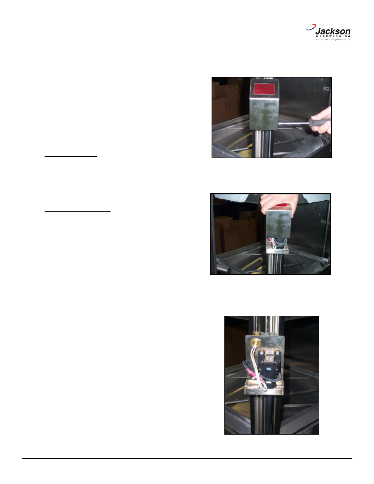
STEPS (Conserver XL)
1. Remove the four screws holding the cover on (Consever XL).
Removing screws for solenoid cover (Conserver XL)
2. Remove the cover by gripping firmly and sliding up.
TIME REQUIRED
It is estimated that it will take (1) person thirty minutes to
perform this task, not including all of the items indicated in the section entitled “PREPARATION”.
IMPORTANT NOTES
1. Read these instructions thoroughly before attempting
this maintenance action. Become familiar with the parts and what
actions need to be taken. This will save time in the long run!
Removing solenoid cover (Conserver XL)
exposed.
Exposed solenoid and wires (Conserver XL)
2
Conserver XL/XL2 Drain Slolenoid Replacement Instructions
Revision A (07/02/2005)
Page 3

4. Using the needle nose pliers, take the bent parts of the cotter pin
8. Gently separate the wires at the terminals. This will electrically
9. Now use the nut driver to remove the (4) locknuts used to mount
11. You may dispose of the drain solenoid. Do not return it to
Jackson unless specifically requested to do so by the Technical
Service Department or a Technical Service Representative. You
12. Before installing your new solenoid, verify that the the voltage
ratings marked on the component correspond to the voltage of the
unit. You can verify the unit’s voltage by referring to the machine
and bend them back so that the pin is relatively straight.
Adjusting the cotter pin (Conserver XL) Separating the wires (Conserver XL)
5. With the pin straightened, pull it out from the opposite side. This
will disconnect the drain link from the solenoid.
www.jacksonmsc.com
disconnect the drain solenoid from the dishmachine.
the solenoid to the dishmachine.
Removing the cotter pin (Conserver XL) Removing the locknut (Conserver XL)
6. Using the wire cutters, remove the tie-wraps that are holding the
wires.
Cutting the tie-wraps (Conserver XL)
7. Note: It is very important that you do not cut or break the insulation on the wires. These wires will carry line voltage and any sort
of breakage can cause dmagae to the unit or harm to personnel. If
you do cut or break the wire(s), the wiring must be repaired in
accordance with national, state and local electrical codes.
10. Remove the old drain solenoid.
Removing the drain solenoid (Conserver XL)
should now retrieve your service kit.
Conserver XL/XL2 Drain Slolenoid Replacement Instructions
Revision A (07/02/2005)
3
Page 4

www.jacksonmsc.com
data plate located on the right side of the tub.
13. Verify that the new solenoid’s slide does not bind and moves
freely before installing it. If it does not, contact Jackson Technical
Service.
Verifying the free movement of the solenoid (Conserver XL)
14. Attach the new drain solenoid to the machine using the (4) locknuts.
15. Reconect the wires to solenoid. Refer to the machine schemat ic if you have any questions regarding the wiring of the solenoid. It
can be found on the inside of the control box cover. If you machine
does not have a schematic, please contact Jackson Technical
Service.
16. Tie-wrap the wires so that they will be out of the way when the
cover is placed back on.
Drain solenoid cover location (Conserver XL2)
Removing the locknut (Conserver XL2)
17. Using the cotter pin, re-attach the drain link. Ensure that after
putting the pin through that you pull back the ends to secure it in
place.
18. Slide the cover back on taking care not to pinch or smash any
wires.
19. Secure the cover using the (4) screws.
20. Proceed to the section entitled “AFTER MAINTENANCE
ACTIONS”.
STEPS (Conserver XL2 Models)
1. Note: These instructions apply to all of the Conserver XL2 mod els, including the Conserver XL2-CML and Conserver XL2-CMR.
2. Locate the cover for the drain solenoid. It is located underneath
the tub on the sump. Using the nutdriver, remove the locknut holding the cover in place. With the locknut removed, push back on the
cover and it should come right off. Do not attempt to pry the cover
off as this could cause damage to the cover, the stud or the wiring
for the drain solenoid.
Removing the cover (Conserver XL2)
The drain solenoid exposed (Conserver XL2)
4
Conserver XL/XL2 Drain Slolenoid Replacement Instructions
Revision A (07/02/2005)
Page 5

3. Once the cover is removed, the drain solenoid and its wiring will
7. Gently separate the wires at the terminals. This will electrically
8. Now use the nut driver to remove the (4) locknuts used to mount
10. You may dispose of the drain solenoid. Do not return it to
Jackson unless specifically requested to do so by the Technical
Service Department or a Technical Service Representative. You
11. Before installing your new solenoid, verify that the the voltage
ratings marked on the component correspond to the voltage of the
unit. You can verify the unit’s voltage by referring to the machine
12. Verify that the new solenoid’s slide does not bind and moves
freely before installing it. If it does not, contact Jackson Technical
-
14. Reconect the wires to solenoid. Refer to the machine schemat
-
ic if you have any questions regarding the wiring of the solenoid. It
can be found on the inside of the control box cover. If you machine
does not have a schematic, please contact Jackson Technical
be exposed.
4. Using the wire cutters, remove the tie-wraps that are holding the
wires.
www.jacksonmsc.com
disconnect the drain solenoid from the dishmachine.
the solenoid to the dishmachine.
Cutting the tie-wraps (Conserver XL2)
5. Note: It is very important that you do not cut or break the insulation on the wires. These wires will carry line voltage and any sort
of breakage can cause dmagae to the unit or harm to personnel. If
you do cut or break the wire(s), the wiring must be repaired in
accordance with national, state and local electrical codes.
6. Using the needle nose pliers, take the bent parts of the cotter pin
and bend them back so that the pin is relatively straight. With the
pin straightened, pull it out from the opposite side. This will disconnect the drain link from the solenoid.
Removing the cotter pin (Conserver XL2)
Removing the locknuts (Conserver XL2)
9. Remove the old drain solenoid.
should now retrieve your service kit.
data plate located on the right side of the tub.
Service.
Separating the wires (Conserver XL2)
Conserver XL/XL2 Drain Slolenoid Replacement Instructions
Revision A (07/02/2005)
Verifying the free movement of the solenoid (Conserver XL)
13. Attach the new drain solenoid to the machine using the (4) lock
nuts.
Service.
5
Page 6

www.jacksonmsc.com
15. Tie-wrap the wires so that they will be out of the way when the
cover is placed back on.
16. Using the cotter pin, re-attach the drain link. Ensure that after
putting the pin through that you pull back the ends to secure it in
place.
17. Slide the cover back on taking care not to pinch or smash any
wires.
18. Secure the cover using the (4) screws.
19. Proceed to the section entitled “AFTER MAINTENANCE
ACTIONS”.
AFTER MAINTENANCE ACTIONS
1. Reconnect the incoming water (if disconnected) and
turn on. Then restore power to the unit. Run the unit for at least 10
cyles to ensure that the drain solenoid is working properly. If any
problems arise you can contact Jackson Technical Service.
SPECIAL NOTES
1. Work performed on Jackson dishmachines by unauthorized or unqualified personnel may void the warranty. Before beginning this or any other maintenance evolution on a unit under warranty, you should contact a certified Jackson technician or Jackson
Technical Service. You can find a list of qualified service agencies
in the back of you unit’s installation manual.
SPECIAL PARTS
Drain Solenoid Replacment Kitt:
For 110 volt machines order 6401-003-08-58
For 230 volt machines order 6401-003-08-59
CONTACT INFORMATION
Jackson MSC Inc. provides technical support for all of the
dishmachines detailed in this manual. We strongly recommend that
you refer to this manual before making a call to our technical sup port staff. Please have this manual with you when you call so that
our staff can refer you, if necessary, to the proper page. Technical
support is available from 8:00 a.m. to 5:00 p.m. (EST), Monday
through Friday. Technical support is not available on holidays.
Contact technical support toll free at 1-888-800-5672. Please
remember that technical support is available for service personnel
only.
6
Conserver XL/XL2 Drain Slolenoid Replacement Instructions
Revision A (07/02/2005)
 Loading...