

Page 1

WHIRL WIZARD
RECIRCULATING SOAK SINK
CONVERSION
INSTALLATION/OPERATIONINSTALLATION/OPERATION
& SERVICE MANUAL& SERVICE MANUAL
Visit Jackson on the Internet at:
www.jacksonmsc.com
July 20, 2000 P/N 7610-011-70-65
Page 2

MANUFACTURERS WARRANTY
ONE YEAR LIMITED PARTS & LABOR WARRANTY
ALL NEW JACKSON DISHWASHERS ARE WARRANTED TO THE ORIGINAL PURCHASER TO BE FREE FROM DEFECTS IN
MATERIAL OR WORKMANSHIP, UNDER NORMAL USE AND OPERATION FOR A PERIOD OF (1) ONE YEAR FROM THE DATE OF
PURCHASE, BUT IN NO EVENT TO EXCEED (18) EIGHTEEN MONTHS FROM THE DATE OF SHIPMENT FROM THE FACTORY.
Jackson MSC agrees under this warranty to repair or replace , at its discretion, any original part which fails under normal use due to
faulty material or workmanship during the warranty period, providing the equipment has been unaltered, and has been properly installed,
maintained and operated in accordance with the applicable factory instruction manual furnished with the machine and the failure is
reported to the authorized service agency within the warranty period. This includes the use of factory specified genuine replacement
parts, purchased directly from a Jackson authorized parts distributor or service agency. Use of generic replacement parts may create
a hazard and void warranty certification.
The labor to repair or replace such failed part will be paid by Jackson MSC, within the continental United States, Hawaii and Canada,
during the warranty period provided a Jackson MSC authorized service agency, or those having prior authorization from the factory, performs the service. Any repair work by persons other than a Jackson MSC authorized service agency is the sole responsibility of the
customer. Labor coverage is limited to regular hourly rates, overtime premiums and emergency service charges will not be paid by
Jackson MSC.
Accessory components not installed by the factory carry a (1) one year parts warranty only. Accessory components such as table limit
switches, pressure regulators, pre rinse units, etc. that are shipped with the unit and installed at the site are included. Labor to repair
or replace these components is not covered by Jackson MSC.
This warranty is void if failure is a direct result from shipping, handling, fire, water, accident, misuse, acts of god, attempted repair by
unauthorized persons, improper installation, if serial number has been removed or altered, or if unit is used for purpose other than it
was originally intended.
TRAVEL LIMITATIONS
Jackson MSC limits warranty travel time to (2) two hours and mileage to (100) one hundred miles. Jackson MSC will not pay for travel
time and mileage that exceeds this, or any fees such as those for air or boat travel without prior authorization.
WARRANTY REGISTRATION CARD
The warranty registration card supplied with the machine must be returned to Jackson MSC within 30 days to validate the warranty.
REPLACEMENT PARTS WARRANTY
Jackson replacement parts are warranted for a period of 90 days from the date of installation or 180 days from the date of shipment
from the factory, which ever occurs first.
PRODUCT CHANGES AND UPDATES
Jackson MSC reserves the right to make changes in design and specification of any equipment as engineering or necessity requires.
THIS IS THE ENTIRE AND ONLY WARRANTY OF JACKSON MSC. JACKSON’S LIABILITY ON ANY CLAIM OF ANY KIND, INCLUD -
ING NEGLIGENCE, WITH RESPECT TO THE GOODS OR SERVICES COVERED HEREUNDER, SHALL IN NO CASE EXCEED THE
PRICE OF THE GOODS OR SERVICES OR PART THEREOF WHICH GIVES RISE TO THE CLAIM.
THERE ARE NO WARRANTIES, EXPRESSED OR IMPLIED, INCLUDING FOR FITNESS OR MERCHANTABILITY, THAT ARE NOT
SET FORTH HEREIN, OR THAT EXTEND BEYOND THE DURATION HEREOF. UNDER NO CIRCUMSTANCES WILL JACKSON
MSC BE LIABLE FOR ANY LOSS OR DAMAGE, DIRECT OR CONSEQUENTIAL, OR FOR THE DAMAGES IN THE NATURE OF
PENALTIES, ARISING OUT OF THE USE OR INABILITY TO USE ANY OF ITS PRODUCTS.
ITEMS NOT COVERED
This warranty does not cover cleaning or deliming of the unit or any component such as, but not limited to, wash arms, rinse arms or
strainers at anytime. Nor does it cover adjustments such as, but not limited to, timer cams, thermostats or doors, beyond 30 days from
the date of installation. In addition, the warranty will only cover the replacement of wear items such as curtains, drain balls, door guides
or gaskets during the first 30 days after installation. Also not covered are conditions caused by the use of incorrect (non-Commercial)
grade detergents, incorrect water temperature or pressure or hard water conditions.
Page 3

TABLE OF CONTENTS
Section Title Page
I General Section
Specifications 1
Detail of the Data Plate 2
General Notes 3
II Installation Instructions 4
III Installation Assembly 5
IV Operation Instructions/Changing Directions 6
V Parts and Drawings
Main Assembly 7
Ordering Replacement Wire 8
Conduit and Fittings 9
Ordering Replacement Fasteners 10
VI Jackson Maintenance and Repair Centers 12
VII 115 Volt, 60 Hz, 1 Phase Schematic 19
VIII Important Information Data Sheet 20
Page 4

SPECIFICATIONS OF THE WHIRL WIZARD
This unit can be adapted to most standard three compartment sink to provide recirculated water to assist in the removal of soil from
ware. The entire unit will fit within the frame work of standard sinks, so no additional floor space is required.
A one (1) horsepower motor and pump continually recirculates warm detergent laden water through a unique agitator mounted in the
drain hole in the sink. The water exits through vanes located on the agitator causing a vortex in the water in the sink. This constant
action, in conjunction with a low sudsing detergent, loosens food soil. A built-in thermostatically controlled heating system maintains
water temperature between 110 and 120 degrees Farenheit.
The unit includes the following:
1. One (1) horsepower pump motor with built-in thermal overload protection.
2. Pump fitted with internal cutting blades.
3. Built-in thermostatically controlled heating system.
4. Illuminated power ON/OFF switch.
5. Heavy duty grounded power cord.
6. 304 stainless steel construction.
ELECTRICAL REQUIREMENTS:
MODEL VOLTS HZ PHASE TOTAL AMPS
WW-1 115 60 3 16.1
1
Page 5
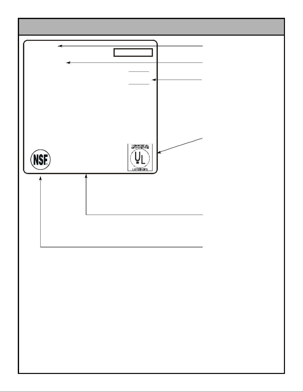
DETAIL OF THE WHIRL WIZARD DATA PLATE
SERIAL NO.:
MODEL:
WASH MOTOR:
HEATER:
TOTAL LOAD
CONNECT TO A MINIMUM 20 AMP SUPPLY - CIRCUIT
PROTECTED WITH A 20 AMP NONTIME - DELAY FUSE
OR OVERCURRENT PROTECTOR
60Hz 1 PH 2 WIRE
1 HP
.4 KW
115 VOLT
13.3 AMPS
2.8 AMPS
16.1 AMPS
MANUFACTURER’S
LOGO
MODEL DESIGNATION
(I.E. “WHIRL WIZARD”)
AMPERAGE LOAD
INFORMATION
UL LOGO (SEE NOTE #1)
MANUFACTURERS
ADDRESS INFORMATION
NSF LOGO (SEE NOTE #2)
The data plate is located on the unit cover. Under no circumstance should the data plate be removed from the unit. The data plate is
essential in identifying the particular characteristics of your machine and is of great benefit to installers, operators, and maintenance
personnel. Do not use the above data plate to represent your machine. The data plate above is a generic representation used only
to show you where to locate information.
2
Page 6

GENERAL NOTES SECTION
Before connecting, operating, or adjusting any of the dishmachines covered in this manual, please carefully read through the entire
manual to familiarize yourself with the machine and its proper operation. This manual contains important operating, safety, and maintenance information concerning your dishmachine. You must follow the instructions and guidelines provided in this manual to ensure
that your warranty remains in effect.
FOR SERVICE PERSONNEL: Jackson MSC Inc. provides technical support for all of the dishmachines detailed in this manual. We
strongly recommend that you refer to this manual before making a call to our technical support staff. Please have this manual with you
when you call so that our staff can refer you, if necessary, to the proper page. Technical support is avaliable from 8:00 a.m. to 5:00 p.m.
(EST), Monday through Friday. Technical support is not available on holidays. Contact technical support toll-free at 1-888-800-5672.
Please remember that technical support is available for service personnel only. Non-service personnel should refer to the list of provided service agencies in this manual for local service support.
NOTES CONCERNING THE DATA PLATES:
This area of the data plate denotes the minimum parameters that must be met in order for your dishmachine to operate at the designed
level of efficiency. Not meeting the required parameters can result in substandard performance of the dishmachine. Do not refer to the
data plate example in this manual for the parameters of your machine; instead, refer to the data plate affixed to the machine. Not every
machine operates the same way. If you are unsure of whether or not you are meeting the required minimum parameters, contact your
nearest Jackson authorized service agency.
NOTE 1: The UL logo on the data plate indicates that this machine is Listed by Underwriters Laboratories Inc. Representative samples
of this product have been evaluated by UL and meet applicable UL Standards and requirements. For more information concerning the
UL logo and UL standards in general, you may visit them on the internet at www.ul.com.
NOTE 2: The NSF logo on the data plate indicates that this machine has been listed under NSF Standard 2 as having met the requirements of that standard. All of Jackson’s NSF-approved machines are listed on the NSF website at www.nsf.org.
3
Page 7

INSTALLATION INSTRUCTIONS
VISUAL INSPECTION: Before installing the unit, check the container and machine for damage. A damaged container is an indicator that the machine may have been hadled roughly during shipping. If there is damage to both the container and the machine, do
not throw away the container. The machine has been inspected at
the factory and is expected to arrive to you in new, undamaged
condition. However, rough handling by carriers or others may
have resulted in damage occuring to the machine. If such a situation does occur, do not return the unit to Jackson. Instead contact
both the dealer you purchased the unit through and the carrier.
Ask the carrier to send a representative out to inspect the damage
and make a report of it. You normally have 48 hours to contact a
carrier to report damages, but this varies based on locale. The
best advice is to contact your carrier and dealer as soon as damage is discovered.
UNPACKING THE MACHINE: Once the machine has been
removed from the container, ensure that there are no obvious
missing parts. This may not be apparent at first glance. If you discover that a part is missing, contact Jackson MSC Inc. immediately.
LEVEL THE MACHINE:
1. Position the Whirl Wizard under the sink drainboard.
2. Adjust left to right and front to back.
3. Align inlet and outlet tubes with plumbing from main flow chamber (item 2).
4. To adjust the height, loosen the allen screws in each leg socket connector.
5. Slide leg out to desired height. The drain connection on the
machine should be at the same level as the sink drain connection.
6. Tighten the allen head screws in each leg socket connector.
7. Fine adjustments in height can be made by turning the bullet
foot in each leg.
INSTALLING THE MACHINE:
1. Locate the sink at the highest end of the drain slope.
7. Tighten the screws in item 6 until the assembly is held in place.
Care must be taken to position screws where they are accessible
and will not be covered by the hose barb when assembled into the
main flow chamber.
8. In the bottom of the main flow chamber (item 2), install the 11/2” NPT close nipple (item 10).
9. The 1-1/2” NPT tee (item 9) is screwed onto the 1-1/2” nipple
(item 10).
10. From the tee (item 9) to the drain, install the following items:
1-1/2” close nipple (item 10) and 1-1/2” ball valve (item 11). Make
sure the handle of the ball valve (item 11) is easily accessible by
the operator.
11. On the sink side of the tee (item 9) install a 1-1/2” NPT hose
barb (item 12).
12. On the inlet side of the main flow chamber (item 2) install a 1”
NPT hose barb (item 8).
13. With different styles and types of sinks, the directional manifold (item 1) may require modification. The directional tubing may
need to be bent to conform to the bottom of the sink or reduced in
length. Since it is fabricated from thin wall stainless steel, a hacksaw can be used to cut the tubing.
HOSE CONNECTIONS:
1. Position the 1-1/2” ID intake line hose (item 13) with the Whirl
Wizard as xlose to the sink as possible, mark and cut to the length
required.
2. Repeat with the 1” ID discharge line hose (item 14).
3. Connect the intake and discharge line hoses with hose clamps
(item 15) to their respective connections.
NOTE: ENSURE THAT THE HOSE CLAMPS ARE TIGHT
BEFORE OPERATING THE UNIT.
CAUTION: IF DIRECT FLOOR DRAIN IS UNDER OR NEAR
MACHINE, MAKE CERTAIN THAT ADEQUATE PROTECTION IS
PROVIDED TO PREVENT WATER SPLATTER FROM DAMAG ING THE UNIT.
2. Disconnect the existing drain plumbing from the sink.
3. Remove the crumb cup.
4. Clean off old plumber’s putty from the sink. Add fresh putty to
the sink flange.
5. Position the main flow chamber (item 2) through the bottom of
the sink. From the bottom, slip the rubber washer (item 3), fiber
washer (item 4), back-up flange (item 5) and mounting flange
(item 6) on the main flow chamber.
6. Once in position, mount the jam spring (item 7) on to the main
flow chamber. This will hold items 3 through 5 in place.
ELECTRICAL POWER CONNECTION:
1. The Whirl Wizard requires a dedicated 20 amp, 115 volt single
phase circuit.
2. A 20 amp NEMA 5-20R receptacle is required for the NEMA 520P cord set and plug shipped with the machine.
CAUTION: A NEMA 5-20R RECEPTACLE IS REQUIRED. IF
NOT AVAILABLE A QUALIFIED ELECTRICIAN SHOULD
INSTALL THE CORRECT RECEPTACLE.
4
Page 8

INSTALLATION ASSEMBLY
1542" Hose Clamp
4730-011-83-17
1
2
8
3
4
5
6
11 12
910
14
15
7
13
ITEM QTY DESCRIPTION MFG No.
1 1 Directional Manifold 5700-031-70-49
2 1 Main Flow Chamber 5700-031-83-05
3 1 Rubber Washer, 3-1/2" Diameter 5330-011-70-87
4 1 Fiber Washer, 3-1/2" Diameter 5330-011-70-48
5 1 Flange, Back-Up 5340-011-83-13
6 1 Mounting Flange 5340-011-83-14
7 1 Spring, Jam 5340-011-83-04
8 1 Hose Barb, 1" NPT to 1" Hose PVC 4730-011-70-36
9 1 Tee, 1-1/2" FNPT, Stainless Steel 4730-011-70-39
10 2 Nipple, Close, 1-1/2" NPT, Stainless Steel 4730-011-70-86
11 1 Ball Valve Assembly 5700-011-70-40
Ball Valve Only 4820-111-71-46
Handle Only 5700-021-70-45
12 1 Hose Barb, 1-1/2" NPT x 1-1/2" PVC 4730-011-70-38
13 1 Hose, 1-1/2" ID x 2'-0" Long 5700-021-69-20
14 1 Hose, 1" ID x 2'-0" Long 5700-021-69-19
5
Page 9

OPERATION INSTRUCTIONS
OPERATION:
1. Install the directional manifold (item 1) into the main flow chamber (item 2).
2. Fill the sink with hot water.
3. Add the proper chemicals (non-foaming detergent) for soaking pots, pans and utensils.
4. Pre-scrap pots, pans and utensils of all large loose soil.
NOTE: THE WHIRL WIZARD POT SINK IS NOT A GARBAGE DISPOSAL! IT IS INTENDED TO SOFTEN SOIL WHICH IS DIFFICULT
TO REMOVE. BAKED-ON SOIL MAY STILL REQUIRE ADDITIONAL EFFORT TO REMOVE.
5. With the power switch in the ON position, place the soiled pots, pans and utensils into the sink.
NOTES: PLACEMENT OF POTS AND PANS SHOULD BE DONE IN A MANNER THAT NOTHING WILL OBSTRUCT THE MAIN
FLOW OF WATER.
6. Allow pots, pans and utensils to soak for 15 to 20 minutes to soften and loosen soil.
CLEANING INSTRUCTIONS:
1. Turn the power switch to the OFF position.
2. Turn the ball valve to the open position and drain the sink.
3. When the sink is empty, remove the directional manifold (rotate counter-clockwise) and clean.
4. Re-install the directional manifold into the main flow chamber.
CHANGING DIRECTION OF MACHINE INSTALLATION:
1. Remove the cover from the Whirl Wizard.
2. Remove the power switch from the side and insert into the pre-punched hole in the opposite end of the unit.
3. To extend the wiring, cut the tie wraps. There is sufficient length to allow the power switch to be relocated.
4. Re-install the cover.
6
Page 10

19
201Decal, Whirl Wizard Logo, Right (Not Shown)
9905-021-70-59
18
17
MAIN ASSEMBLY
1
2
3
15
5
4 16
6
8, 9 7 14
12 10
ITEM QTY DESCRIPTION MFG No.
1 1 Cover Assembly 5700-021-70-31
2 1 Box Bottom 5700-031-67-89
3 2 Screw, 10-32 x 1/2" Long, Truss Head 5305-011-39-36
4 4 Leg Assembly with Bullet Foot 5700-021-67-93
5 4 Bullet Foot 5340-108-01-03
6 1 Pump and Motor Assembly 6105-021-69-18
7 1 Chopper Assembly 5700-021-70-32
8 4 Locknut, 1/4"-20 with Nylon Insert 5310-374-01-00
9 4 Flat Washer, 1/4" 5311-174-01-00
10 1 Inlet Plumbing 5700-031-68-31
11 1 "J" Tube, Outlet 5700-021-68-60
12 1 Suction Connector Tube 5700-011-70-33
13 1 Discharge Connector Tube 5700-011-70-34
14 4 Hose Clamp, 2" 4730-719-01-37
15 1 Heater, Flexible, 120 Volts, 400 Watts 4540-021-70-21
16 1 Contactor, Motor 5945-109-05-69
17 1 Power Switch 5930-011-82-72
18 1 Power Cord 6145-011-70-28
19 1 Decal Whirl Wizard Logo, Left 9905-021-70-64
7
Page 11

ORDERING REPLACEMENT WIRE
ORDERING REPLACEMENT WIRE FOR YOUR DISHMACHINE
Jackson dishmachines have several color and gauges of wire used in them and it may become necessary to replace these wires.
Wire may be ordered from Jackson MSC Inc., but please note that it is only available in feet. Ensure that you order the correct color
and guage.
BLACK WIRE:
RED WIRE:
6 Gauge 6145-002-15-91
8 Gauge 6145-104-43-00
10 Gauge 6145-104-16-00
12 Gauge 6145-112-01-00
14 Gauge 6145-104-09-00
18 Gauge 6145-104-01-97
18 Gauge with Orange Stripes 6145-011-35-66
18 Gauge with White Stripes 6145-011-35-65
18 Gauge with Yellow Stripes 6145-011-35-64
BLUE WIRE:
6 Gauge 6145-002-15-92
8 Gauge 6145-104-45-00
10 Gauge 6145-104-08-00
14 Gauge 6145-104-05-00
18 Gauge 6145-104-37-00
18 Gauge with Black Stripes 6145-011-59-56
18 Gauge with Blue Stripes 6145-011-81-74
18 Gauge with White Stripes 6145-011-81-73
18 Gauge with Yellow Stripes 6145-011-81-75
20 Gauge 6145-104-02-97
6 Gauge 6145-002-15-93
8 Gauge 6145-104-44-00
10 Gauge 6145-104-42-00
14 Gauge 6145-104-04-00
18 Gauge 6145-104-35-00
18 Gauge with Black Stripes 6145-011-46-35
18 Gauge with Red Stripes 6145-011-46-37
18 Gauge with White Stripes 6145-011-46-36
18 Gauge with Yellow Stripes 6145-011-46-38
20 Gauge 6145-104-06-97
20 Gauge with Black Stripes 6145-104-17-97
20 Gauge with White Stripes 6145-104-13-97
GREEN WIRE:
8 Gauge 6145-002-15-94
14 Gauge 6145-104-03-00
18 Gauge 6145-104-32-00
18 Gauge with Yellow Stripes 6145-001-44-96
20 Gauge 6145-104-05-97
20 Gauge with Black Stripes 6145-011-59-57
20 Gauge with Yellow Stripes 6145-104-11-97
GREY WIRE:
18 Gauge 6145-104-36-00
18 Gauge with Black Stripes 6145-011-81-71
18 Gauge with Blue Stripes 6145-011-81-72
18 Gauge with Red Stripes 6145-011-46-41
18 Gauge with White Stripes 6145-011-35-60
18 Gauge with Yellow Stripes 6145-011-46-42
20 Gauge 6145-104-03-97
WHITE WIRE:
10 Gauge 6145-104-19-00
14 Gauge 6145-104-10-00
18 Gauge 6145-104-39-00
18 Gauge with Black Stripes 6145-011-35-70
18 Gauge with Blue Stripes 6145-011-46-40
18 Gauge with Green Stripes 6145-011-35-69
18 Gauge with Grey Stripes 6145-002-20-18
18 Gauge with Red Stripes 6145-011-35-67
18 Gauge with Yellow Stripes 6145-011-35-68
20 Gauge 6145-104-04-97
20 Gauge with Orange & Yellow Stripes 6145-104-16-97
20 Gauge with Yellow Stripes 6145-104-15-97
YELLOW WIRE:
18 Gauge 6145-104-33-00
18 Gauge with Black Stripes 6145-011-81-68
18 Gauge with Blue Stripes 6145-011-81-70
18 Gauge with Red Stripes 6145-011-81-69
20 Gauge 6145-104-07-97
8
Page 12

ORDERING REPLACEMENT WIRE (CONTINUED)/CONDUIT & FITTINGS
MISCELLANEOUS WIRE:
Brown (18 Gauge) 6145-104-20-00
Brown (20 Gauge) 6145-104-08-97
Orange (18 Gauge) 6145-104-34-00
Orange with Black Stripes (18 Gauge) 6145-011-35-62
Orange with Blue Stripes (18 Gauge) 6145-011-46-39
Orange with White Stripes (18 Gauge) 6145-011-35-63
Orange with Yellow Stripes (18 Gauge) 6145-011-35-61
Orange (20 Gauge) 6145-104-10-97
Pink (18 Gauge) 6145-011-82-69
Purple (18 Gauge) 6145-104-31-00
Violet (20 Gauge) 6145-104-09-97
Plug, GFI 6145-001-97-90
Cable, 16 Gauge, 3 Wire Romex 6145-001-98-29
Cord, Hubble Plug MC 6145-011-47-23
Cord, S-J 6145-011-49-02
Cord, Power 6145-011-70-28
Cord, 115V Power 6145-309-02-00
Cord, 125V Power, 96 “ Long 6145-309-04-00
CONDUIT AND RELATED FITTINGS
Jackson dishmachines come with a wide variety of conduit and fittings for use in routing the wires of the machine. The list below
provides for most of stock of such items. When ordering, remember that Jackson does not offer pre-cut sections of conduit for your
machine, instead it is sold by the foot. Please take into account in slack that will be necessary once installing the new conduit to
ensure that it fits correctly. It is recommended that you order at least 6” more conduit than you require to ensure that you have
enough for trimming.
CONDUIT:
Conduit, 1/2”, Liquidtite 5975-101-25-00
Conduit, 1/2”, Non-Metallic 5975-111-46-57
Conduit, 1/2”, PVC 5975-105-04-00
Conduit, 1/2”, Sealtite 5975-105-01-00
Conduit, 1/2”, Xtraflex 5975-105-06-44
Conduit, 3/8”, Liquidtite 5975-105-02-00
Conduit, 3/4”, Cole-Flex 5975-105-05-00
Conduit, 3/4”, Liquidtite 5975-105-03-00
Conduit, 3/4”, Non-Metallic 5975-011-47-71
Conduit, 3/4” Xtraflex 5975-105-07-44
Conduit, 1”, Carlon 5975-011-68-42
CONDUIT FITTINGS:
Elbow, Cole-Flex, 1/2”, 90 Degree 5975-205-40-00
Elbow, Xtraflex, 1/2”, 90 Degree 5975-205-44-44
Elbow, Xtraflex, 3/4”, 90 Degree 5975-205-45-44
Fitting, 1/2” Straight 5975-011-45-13
Fitting, 1/2”, Straight, Zinc Plated 5975-111-89-89
Fitting, 1/2”, 45 Degree 5975-011-45-23
Fitting, 1/2”, 45 Degree, Zinc Plated 5975-111-89-86
Fitting, 1/2”, 90 Degree 5975-011-45-14
Fitting, 1/2”, 90 Degree, Zinc Plated 5975-111-89-88
Fitting, 3/4”, Straight 5975-011-47-72
Fitting, 3/4”, 45 Degree 5975-011-47-74
Fitting, 3/4”, 90 Degree 5975-011-47-73
Fitting, 1”, Straight 5975-011-70-75
Fitting, 1”, 90 Degree 5975-011-68-43
Fitting, Cole-Flex, 1/2” Straight 5975-205-03-00
Fitting, Cole-Flex, 3/4” Straight 5975-205-41-00
Fitting, Cole-Flex, 3/4”, 90 Degree 5975-204-42-00
Fitting, Liquidtite, .231 ID/.394 OD 5975-011-49-03
Fitting, Liquidtite, .25 ID/.546 OD 5975-011-65-51
Fitting, Liquidtite, .27 ID/.48 OD 5975-011-59-50
Fitting, Liquidtite, 1/2”, 90 Degree 5975-111-01-00
Fitting, Liquidtite, 3/8”, Straight 5975-205-03-82
Fitting, Liquidtite, 3/8”, 90 Degree 5975-205-02-82
Fitting, Liquidtite, 3/4”, Straight 5975-205-15-02
Fitting, Liquidtite, 3/4”, 45 Degree 5975-205-01-82
Fitting, Liquidtite, 3/4”, 90 Degree 5975-205-07-82
Fitting, Xtraflex, 1/2”, Straight 5975-205-47-44
Fitting, Xtraflex, 3/4”, Straight 5975-205-46-44
Nut, 1-1/4” 5975-011-42-54
9
Page 13

ORDERING REPLACEMENT FASTENERS
Dishmachines come with a variety of fasteners used to hold them together. On the following pages will be comprehensive list of all
of the fasteners you may order. Jackson reserves the right to require minimum quantities to be ordered.
SCREWS:
Screw, 1/4”-20 x 1/4”, Set 5305-002-10-14
Screw, 1/4”-20 x 1/2”, Phillips Truss Head 5305-174-03-00
Screw, 1/4”-20 x 1/2”, Set Screw 5305-011-71-51
Screw, 1/4”-20 x 1/2”, Slotted Truss Head 5305-002-22-81
Screw, 1/4”-20 x 1/2”, Thumb 5305-011-38-62
Screw, 1/4”-20 x 1/2”, with Rubber Washer 5305-974-01-00
Screw, 1/4”-20 x 5/8”, 80 Deg CSink 5305-002-20-30
Screw, 1/4”-20 x 5/8”, Hex Head 5305-274-24-00
Screw, 1/4”-20 x 5/8”, Phillips Truss Head 5305-174-04-00
Screw, 1/4”-20 x 1-1/8”, Hex Head 5305-274-21-00
Screw, 1/4”-20 x 1-1/4”, Flat Head 5305-174-19-00
Screw, 1/4”-20 x 1-3/8”, Hex Head 5305-274-19-00
Screw, 1/4”-20 x 1-1/2”, Flat Head 5305-174-11-00
Screw, 1/4”-20 x 1-1/2”, Hex Head 5305-274-23-00
Screw, 1/4”-20 x 1-1/2”, Phillips Head 5305-011-44-50
Screw, 1/4”-20 x 1-1/2”, Slotted Truss Hd 5305-002-22-82
Screw, 1/4”-20 x 1-3/4”, Hex Head 5305-274-10-00
Screw, 1/4”-20 x 3-3/4”, Hex Head 5305-011-93-68
Screw, 5/16”-18 x 1/2”, Hex Head 5306-011-88-67
Screw, 5/16”-18 x 1-1/4”, Flat Head 5305-011-83-49
Screw, 3/8”-16 x 1”, Socket Head 5305-356-04-00
Screw, 3/8”-16 x 1-1/4”, Hex Head Plated 5305-256-04-00
Screw, 3/8”-16 x 2”, Cap 5305-011-74-98
Screw, 4-40 x 1/4”, Phillips Pan Head 5305-011-36-92
Screw, 4-40 x 3/8”, Phillips Truss Head 5305-011-59-70
Screw, 4-40 x 1/2” Phillips Pan Head 5305-011-38-19
Screw, 4-40 x 5/8” Phillips Truss Head 5305-011-49-70
Screw, 4-40 x 3/4”, Phillips Pan Head 5305-011-59-64
Screw, 4-40 x 1”, Slotted Pan Head 5305-179-01-00
Screw, 6-32 x 1/4”, Flat Head 5305-171-01-00
Screw, 6-32 x 1/4”, Round Head 5305-151-02-00
Screw, 6-32 x 1/2”, Phillips Head 5305-171-15-00
Screw, 6-32 x 1/2”, Phillips Truss Head 5305-011-39-34
Screw, 6-32 x 3/8”, Phillips Head 5305-171-02-00
Screw, 6-32 x 3/8”, Phillips Round Head 5305-171-07-00
Screw, 6-32 x 5/8”, Phillips Round Head 5305-011-39-85
Screw, 6-32 x 3/4”, Round Head 5305-171-03-00
Screw, 6-32 x 3/4”, Phillips Pan Head 5305-011-37-05
Screw, 6-32 x 7/8”, Phillips Round Head 5305-171-10-00
Screw, 8-32 x 1/4”, Phillips Pan Head 5305-172-09-00
Screw, 8-32 x 1/4”, Slotted Round Head 5305-172-01-00
Screw, 8-32 x 3/8”, Phillips Flat Head 5305-776-03-00
Screw, 8-32 x 3/8”, Phillips Flat Head 5305-011-37-07
Screw, 8-32 x 3/8”, Round Head 5305-172-02-00
Screw, 8-32 x 1/2”, Hex Head 5305-002-02-87
Screw, 8-32 x 1/2”, Phillips Flat Head 5305-011-37-06
Screw, 8-32 x 3/4”, Phillips Round Head 5305-172-06-00
Screw, 10-24 x 3/8”, Flat Head Undercut 5305-773-02-00
Screw, 10-24 x 3/8”, Phillips Truss Head 5305-173-03-00
Screw, 10-24 x 1/2”, Phillips Truss Head 5305-173-18-00
Screw, 10-24 x 1/2”, Set 5305-473-02-00
Screw, 10-24 x 5/8”, Hex Head 5305-011-40-89
Screw, 10-24 x 3/4”, Hex Head 5305-273-05-00
Screw, 10-24 x 2-1/4”, Hex Head 5305-011-38-10
Screw, 10-32 x 1/4”, Round Head 5305-173-01-00
Screw, 10-32 x 3/8”, Phillips Pan Head 5305-173-26-00
Screw, 10-32 x 3/8”, Phillips Truss Head 5305-173-12-00
Screw, 10-32 x 3/8”, Round Head, Slotted 5305-173-02-00
Screw, 10-32 x 1/2”, Phillips Flat Head 5305-011-44-51
Screw, 10-32 x 1/2”, Phillips Pan Head 5305-011-44-52
Screw, 10-32 x 1/2”, Phillips Truss Head 5305-011-39-36
Screw, 10-32 x 1/2”, Self Tapping 5305-011-62-69
Screw, 10-32 x 1/2”, Slotted Truss 5305-173-04-00
Screw, 10-32 x 5/8”, Fillister Head 5305-973-02-00
Screw, 10-32 x 3/4”, Shoulder, .25 Shoulder 5305-011-86-65
Screw, 10-32 x 3/4”, Phillips Truss Head 5305-011-62-17
Screw, 10-32 x 3/4”, Phillips Truss Head 5305-011-49-33
Screw, 10-32 x 7/8”, Fillister Head 5305-973-04-00
Screw, 10-32 x 7/8”, Hex Head 5305-279-01-00
Screw, 10-32 x 1”, Phillips Pan Head 5305-002-19-42
Screw, 10-32 x 1-1/8” Fillister Head 5305-973-03-00
Screw, 10-32 x 1-1/4”, Phillips Truss Head 5305-011-66-03
Screw, 10-32 x 1-1/4”, Socket Head 5305-356-16-00
Screw, 10-32 x 1-1/2”, Fillister Head 5305-973-01-00
Screw, 10-32 x 1-3/4”, Phillips Pan Head 5305-011-62-67
Screw, 10-32 x 1-3/4”, Self Tapping 5305-011-59-92
BOLTS:
Bolt, 1/4”-20 x 3/8”, Hex Head 5305-274-20-00
Bolt, 1/4”-20 x 1/2”, Hex Head 5305-274-02-00
Bolt, 1/4”-20 x 3/4”, Hex Head 5305-274-04-00
Bolt, 1/4”-20 x 7/8”, Hex Head 5305-274-05-00
Bolt, 1/4”-20 x 1”, Hex Head 5305-254-06-00
Bolt, 1/4”-20 x 1-1/4”, Hex Head 5305-274-22-00
Bolt, 1/4”-20 x 2”, Hex Head 5306-011-84-72
Bolt, 1/4”-20 x 2-1/4”, Hex Head 5305-011-30-50
Bolt, 1/4”-20 x 2-1/2”, Hex Head 5306-011-83-52
Bolt, 1/4”-20 x 2-3/4”, Hex Head 5306-011-46-62
Bolt, 1/4”-20 x 3-1/4”, Hex Head 5306-002-05-55
Bolt, 5/16”-18 x 5/8”, Hex Head 5305-275-09-00
Bolt, 5/16”-18 x 3/4”, Hex Head 5305-275-04-00
Bolt, 5/16”-18 x 1” , Hex Head 5305-275-06-00
Bolt, 5/16”-18 x 1-1/4”, Hex Head 5305-275-10-00
Bolt, 3/8”-16 x 3/4”, Hex Head 5306-011-71-60
Bolt, 3/8”-16 x 7/8”, Hex Head 5306-011-36-95
Bolt, 3/8”-16 x 1”, Hex Head 5305-276-03-00
Bolt, 3/8”-16 x 1”, Hex Head, Plated 5305-256-03-00
Bolt, 3/8”-16 x 1-1/4”, Hex Head 5305-276-10-00
Bolt, 3/8”-16 x 1-3/4”, Hex Head 5306-011-36-94
Bolt, 3/8”-16 x 2-1/4”, Hex Head 5306-011-95-12
Bolt, 3/8”-16 x 2-3/4”, U-Bolt 5306-011-51-34
Bolt, 3/8”-16 x 4”, Hex Head 5306-956-02-00
Bolt, 1/2”-13 x 1-3/4” 5305-011-71-94
Bolt, 10-24 x 3/8”, Hex Head 5306-011-63-29
Bolt, 10-32 x 3/8” 5306-011-62-45
10
Page 14

ORDERING REPLACEMENT FASTENERS (CONTINUED)
LOCKWASHERS:
Lockwasher, 1/4”, Split 5311-274-01-00
Lockwasher, 3/8”, Split 5311-276-01-00
Lockwasher, 3/8”, Split 5311-256-01-00
Lockwasher, 5/8” 5311-278-02-00
Lockwasher, 5/16”, Split 5311-275-01-00
Lockwasher, 5/16”, Split, Cad Plated 5311-255-01-00
Lockwasher, #4, External Tooth 5311-011-59-70
Lockwasher, #6 External Tooth 5311-271-02-00
Lockwasher, #8 5311-272-02-00
Lockwasher, #8, External Tooth 5311-272-01-00
Lockwasher, #8, Internal Tooth 5311-272-03-00
Lockwasher, #10, External Tooth 5311-273-02-00
Lockwasher, #10, Internal Tooth 5311-273-03-00
Lockwasher, #10, Split 5311-273-01-00
FLAT WASHERS:
Washer, Flat, Brass, 3/32” ID 5311-129-08-00
Washer, Flat, Brass, 1/4” ID 5311-129-09-00
Washer, 1/4” ID x 3/4” OD 5311-011-76-30
Washer, Flat, 5/16” ID 5311-175-01-00
Washer, Flat, Brass, 5/16”, Cadplated 5311-156-01-00
Washer, Flat, S/S, 3/8” ID 5311-176-01-00
Washer, 3/8” ID x 9/16” OD 5311-011-71-49
Washer, 1/2” ID x 1” OD x 1/8” Thick 5311-011-71-48
Washer, 1/2” ID x 1-5/16” OD, Cadplated 5311-157-01-00
Washer, Nylon, .51” ID x .76” OD 5311-011-62-65
Washer, Flat, S/S, 11/16 “ ID x 1/2” OD 5311-178-01-00
Washer, 7/8” ID x 1-1/2” OD 5311-011-35-37
Washer, Flat, 1/4” ID 5311-174-01-00
Washer, Flat, #10 5311-173-02-00
LOCKNUTS:
Locknut, 1/4”-20 with Nylon, High Profile 5310-374-01-00
Locknut, 1/4”-20 with Nylon, Low Profile 5310-374-02-00
Locknut, 5/16”-24 with Nylon, High Profile 5310-375-01-00
Locknut, 5/16”-24 with Nylon, Low Profile 5310-374-03-00
Locknut, 3/8”-16, with Nylon, High Profile 5310-011-72-55
Locknut, 3/8”-16, with Nylon, Low Profile 5310-376-02-00
Locknut, 4-40, with Nylon 5310-279-06-00
Locknut, 6-32, with Nylon 5310-373-03-00
Locknut, 10-24, with Nylon 5310-373-01-00
Locknut, 10-32, with Nylon 5310-373-02-00
HEX NUTS:
Nut, Hex, 1/4”-20 5310-274-01-00
Nut, Hex, 1/4”-20, Cad Plated 5310-254-01-00
Nut, Hex, 5/16”-18 5310-275-01-00
Nut, Hex, 5/16”-18, Cad Plated 5310-255-01-00
Nut, Hex, 3/8”-16 5310-276-02-00
Nut, Hex, 3/8”-16, Cad Plated 5310-256-02-00
Nut, Hex, 1/2”-13 5310-011-72-58
Nut, Hex, 6-32 5310-271-01-00
Nut, Hex, 8-32 5310-272-01-00
Nut, Hex, 10-24 5310-273-02-00
Nut, Hex, 10-32 5310-273-01-00
MISCELLANEOUS NUTS:
Nut, 1/4”-20, Acorn 5310-174-01-00
Nut, 1/4”-20, Hex, Serrated 5310-011-66-49
Nut, 1/4”-20, Wing, Nylon 5310-994-01-00
Nut, 5/16”-18, Keps 5310-955-01-00
Nut, 5/8”-18, Brass 5310-228-01-11
Nut, 6-32, Keps 5310-002-24-29
Nut, 10-24, Hex Cap 5310-173-01-00
Nut, 10-24, Wing, Nylon 5310-993-01-00
11
Page 15

JACKSON MAINTENANCE & REPAIR CENTERS (USA)
ALABAMA
Jones-McLeod Appliance
1616 7th Avenue North
Birmingham, AL 35203
(205) 251-0159
(800) 821-1150
(205) 322-1440 fax
Jones-McLeod Appliance
854 Lakeside Drive
Mobile, AL 36693
(334) 666-7278
(800) 237-9859
(334) 661-0223 fax
ALASKA
Restaurant Appliance Service
7219 Roosevelt Way NE
Seattle, WA 98115
(206) 524-8200
(800) 433-9390
(206) 525-2890 fax
ARIZONA
GCS Service, Inc. #78
5052 South 40th Street
Phoenix, AZ 85040
(602) 474-4510
(800) 510-3497
(602) 470- 4511 fax
Authorized Commercial
Food Equipment Service
4832 South 35th St.
Phoenix, AZ 85040
(602) 234-2443
(800) 824-8875
(602) 232-5862 fax
ARKANSAS
Bromely Parts & Service
10th & Ringo
P.O. Box 1688
Little Rock, AR 72202
(501) 374-0281
(800) 482-9269
(501) 374-8352 fax
Commercial Parts & Service
3717 Cherry Road
Memphis, TN 38118
(901) 366-4587
(800) 262-9155
(901) 366-4588 fax
CALIFORNIA
P & D Appliance
4220-C Roseville Road
North Highlands, CA 95660
(916) 974-2772
(800) 824-7219
(916) 974-2774
CALIFORNIA (cont)
P & D Appliance
100 South Linden Avenue
S. San Francisco, CA 94080
(650) 635-1900
(800) 424-1414
(650) 635-1919 fax
Barkers Food
Machinery Equipment
5367 Second Street
Irwindale, CA 91706
(626) 960-9390
(800) 258-6999
(626) 337-4541 fax
GCS Service, Inc. #24
1100 East Pico Blvd
Los Angeles, CA 90021
(213) 683-2090
(800) 327-1433
(213) 683-2099 fax
GCS Service, Inc. #24
650 S. Grand Avenue
Suite 111
Santa Ana, CA 92705
(714) 542-1798
(800) 540-0719
(714) 542-4787 fax
GCS Service, Inc. #52
360 Littlefield
S. San Francisco, CA 94080
(650) 635-0720
(800) 969-4427
(650) 871-4019 fax
GCS Service, Inc. # 84
9030 Kenamar Drive
Suite 313
San Diego, CA 92121
(858) 549-8411
(800) 422-7278
(858) 549-2323 fax
COLORADO
GCS Service, Inc. #60
4251 S. Natches Ct.
Unit C
Sheridan, Co 80110
(303) 371-9054
(800) 972-5314
Metro Appliance Service
1640 South Broadway
Denver, CO 80210
(303) 778-1126
(800) 525-3532
(303) 778-0268 fax
CONNECTICUT
GCS Service, Inc. #06
302 Murphy Road
Hartford, CT 06114
(860) 549-5575
(800) 423-1562
(860) 527-6355 fax
DELAWARE
Food Service Equipment
2101 Parkway South
Broomall, PA 19008
(610) 356-6900
(610) 356-2038 fax
GCS Service, Inc. #44
817 N. Third Street
P.O. Box 3564
Philadelphia, PA 19123
(215) 925-6217
(800) 441-9115
(215) 925-6208 fax
Elmer Schultz Service
36 Belmont Ave.
Wilmington, DE 19804
(302) 655-8900
(800) 225-0599
(302) 656-3673 fax
EMR Service Division
106 Willamsport Circle
Salisbury, MD 21804
(410) 543-8197
(410) 543-4038 fax
FLORIDA
GCS Service, Inc. #15
3373 N. W. 168th Street
Miami, FL 33056
(305) 621-6666
(800) 766-8966
(305) 621-6656 fax
Commercial Appliance Service
8416 Laurel Fair Circle
Building 6, Suite 114
Tampa, FL 33610
(813) 663-0313
(800) 282-4718
(813) 663-0212 fax
GCS Service, Inc. #14
3902 Corporex Park Drive
Suite 350
Tampa, FL 33619
(813) 626-6044
(800) 282-3008
(813) 621-1174
12
Page 16

JACKSON MAINTENANCE & REPAIR CENTERS (USA)
FLORIDA (cont)
GCS Service, Inc. # 13
4305 Vineland Road
Suite G-12
Orlando, FL 32811
(407) 841-2551
(800) 338-7322
(407) 423-8425 fax
Jones-McLeod Appliance
854 Lakeside Drive
Mobile, AL 36693
(334) 666-7278
(800) 237-9859
(334) 661-0223 fax
GEORGIA
GCS Service, Inc. #16
3127Presidential Dr.
Atlanta, GA 30340
(770) 452-7322
(300) 334-3599
(770) 452-7473 fax
Southeastern
Restaurant Service
2200 Norcross Pkwy,
Suite 210
Norcross, GA 30071
(770) 446-6177
(800) 235-6516
(770) 446-3157 fax
Whaley Foodservice Repairs
109-A Owens Industrial Drive
Savannah, GA 31405
(912) 447-0827
(888) 765-0036
(912) 447-0826 fax
HAWAII
Food Equipment Parts &
Service Co.
300 Puuhale Road
Honolulu, HI 96819
(808) 847-4871
(808) 842-1560 fax
IDAHO
Ron’s Service
703 E. 44th Street, Suite 10
Garden City, ID 83714
(208) 375-4073
(208) 375-4402 fax
Restaurant Appliance Service
7219 Roosevelt Way Ne
Seattle, WA 98115
(206) 524-8200
(800) 433-9390
(206) 525-2890 fax
ILLINOIS
INDIANA
IOWA
KANSAS
GCS Service Inc. #12
696 Larch Avenue
Elmhurst, IL 60126
(630) 941-7800
(800) 942-9689
(630) 941-6048 fax
Cone’s Repair Service
2408 40th Avenue
Moline, IL 61265
(309) 797-5323
(800) 716-7070
(309) 797-3631 fax
Eichenauer Services, Inc.
130 S. Oakland Street
Decatur, IL 62522
(217) 429-4229
(800) 252-5892
(217) 429-0226 fax
GCS Service, Inc. #80
9722 Reavis Park Drive
St. Louis, MO 63123
(314) 638-7444
(800) 284-4427
(314) 638-0135 fax
Commercial Parts and Service
5310 E. 25th Street
Indianapolis, IN 46218
(317) 545-9655
(800) 727-8710
(317) 549-6286 fax
Goodwin-Tucker Group
3509 Delaware Avenue
Des Moines, IA 50313
(515) 262-9308
(800) 372-6066
(515) 262-2936 fax
Cone’s Repair Service
1056 27th Ave. SW
Cedar Rapids, IA 52404
(319) 365-3325
(800) 747-3326
(319) 365-0885 fax
GCS Service Inc. #82
6107 Connecticut
Kansas City, MO 64120
(816) 920-5999
(800) 229-6477
(816) 920-7387 fax
KENTUCKY
Certified Service Center
Ramco Business Park
4283 Produce Road
Louisville, Ky 40218
(502) 964-7007
(800) 637-6350
(502) 964-7202 fax
Commercial Parts & Service
4204 South Brook Street
Louisville, KY 40214
(502) 367-1788
(800) 752-6160
(502) 367-0400 fax
Certified Service Center
1051 Goodwin Drive
Lexington, KY 40505
(606) 254-8854
(800) 432-9269
(606) 231-7781 fax
Commercial Parts & Service
1002 Nandino Blvd.
Lexington, KY 40511
(606) 255-0746
(800) 432-9260
(606) 255-0748 fax
LOUISIANA
Bana Parts, Inc.
1501 Kueble Street
Harahan, LA 70123
(504) 734-0076
(800) 325-7543
(504) 734-8456 fax
Bana Parts, Inc.
4028 Greenwood Road
Shreveport, LA 71109
(318) 631-6550
(800) 832-6550
(318) 636-5675 fax
MAINE
GCS Service, Inc. #09
180 Second Street
Chelsea, MA 02150
(617) 889-9393
(800) 225-1155
(617) 889-1222 fax
Massachusetts Restaurant
Supply
34 South Street
Somerville, MA 02143
(617) 868-1930
(800) 338-6737
(617) 868-5331 fax
13
Page 17

JACKSON MAINTENANCE & REPAIR CENTERS (USA)
MARYLAND
GCS Service, Inc. #07
2660 Pittman Drive
Silver Spring, MD 20910
(301) 585-7550 (DC)
(410) 792-0388 (Balt)
(800) 638-7278
(301) 495-4410 fax
EMR Service Division
700 East 25th Street
Baltimore, MD 21218
(410) 467-8080
(800) 879-4994
(410) 467-4191 fax
EMR Service Division
106 Willamsport Circle
Salisbury, MD 21804
(410) 543-8197
(888) 687-8080
(410) 548-4038 fax
EMR Service Division
2626 Pittman Drive
Silver Spring, MD 20910
(301) 588-8080
(800) 348-2365
(301) 588-6985 fax
MASSACHUSETTS
GCS Service, Inc. #09
180 Second Street
Chelsea, MA 02150
(617) 889-9393
(800) 225-1155
(617) 889-1222 fax
MICHIGAN
GCS Service, Inc. #20
31829 West Eight Mile Road
Livonia, MI 48152
(248) 426-9500
(800) 772-2936
(248) 426-7555 fax
GCS Service, Inc. #21
3516 Roger B Chaffe SE
Grand Rapids, MI 49548
(248) 426-9500
(800) 772-2936
(248) 426-7555 fax
Jackson Service
3980 Benstein Road
Commerce Township, MI 48382
(248) 363-4159
(800) 332-4053
(248) 363-5448 fax
MINNESOTA
GCS/Metro Service, Inc.
2857 Louisiana Avenue N.
Minneapolis, MN 55427
(612) 546-4221
(800) 345-4221
(612) 546-4286 fax
MISSISSIPPI
Commercial Parts & Service
5755 Gallant Drive
Jackson, MS 39206
(601) 956-7800
(800) 274-5954
(601) 956-1200 fax
MISSOURI (cont)
Kammerlin Parts & Service
2728 Locust Street
St. Louis, MO 63103
(314) 535-2222
(314) 535-6205 fax
MONTANA
Restaurant Appliance Service
7219 Roosevelt Way NE
Seattle, WA 98115
(206) 524-8200
(800) 433-9390
(206) 525-2890 fax
NEBRASKA
Goodwin-Tucker Group
815 N. 19th Street
Omaha, NE 68102
(402) 345-7400
(800) 228-0342
(402) 346-6145 fax
NEVADA
GCS Service, Inc. #77
3585 East Patrick Lane
Suite 1000
Las Vegas, NV 89102
(702) 450-3495
(800) 500-9060
(702) 450-3491 fax
Burney’s Commercial Service
4480 Aldevaran Avenue
Las Vegas, NV 89103
(702) 736-0006
(702) 798-7531 fax
Massachusetts Restaurant
Supply
34 South Street
Somerville, MA 02143
(617) 868-1930
(800) 338-6737
(617) 868-5331 fax
Ace Service Co.
95 Hampton Avenue
Needham, MA 02494
(781) 449-4220
(800) 225-4510 MA & NH
(781) 444-4789 fax
GCS Service, Inc. #06
302 Murphy Road
Hartford, CT 06114
(860) 549-5575
(800) 723-1562
(860) 527-6355 fax
Commercial Parts & Service
3717 Cherry Road
Memphis, TN 38118
(901) 366-4587
(800) 262-9155
(901) 366-4588 fax
MISSOURI
GCS Service, Inc. #82
6107 Connecticut
Kansas City, MO 64120
(816) 920-5999
(800) 229-6477
(816)920-7387 fax
GCS Service, Inc. # 80
9722 Reavis Park Drive
St. Louis, MO 63123
(314) 638-7444
(800) 284-4427
(314) 638-0135 fax
NEW HAMPSHIRE
GCS Service, Inc. #09
180 Second Street
Chelsea, MA 02150
(617) 889-9393
(800) 225-1155
(617) 889-1222 fax
Massachusetts Restaurant
Supply
34 South Street
Somerville, MA 02143
(617) 868-1930
(800) 338-6737
(617) 868-5331 fax
Ace Service Co.
95 Hampton Avenue
Needham, MA 02494
(781) 449-4220
(800) 225-4510 MA & NH
(781) 444-4789 fax
14
Page 18

JACKSON MAINTENANCE & REPAIR CENTERS (USA)
NEW JERSEY
Jackson Faspray Service
155 Sargeant Avenue
Clifton, NJ 07013
(973) 471-8000
(800) 356-6740
(973) 471-1289 fax
GCS Service, Inc. #44
817 N. Third Street
Philadelphia, PA 19123
(215) 925-6217
(800) 441-9115
(215) 925-6208 fax
GCS Service, Inc. #02
1 Madison ST., Bldg. F
E. Rutherford, NJ 07073
(973) 614-0003
(800) 399-8294
(973) 614-0320 fax
Food Service Equipment
2101 Parkway South
Broomall, PA 19123
(610) 356-6900
(610) 356-2038 fax
NEW MEXICO
Stove Parts Supply Co.
2120 Solana Street
Ft. Worth, TX 76117
(817) 831-0381
(800) 433-1804
(817) 834-7754 fax
NEW YORK
GCS Service, Inc. #01
932 Grand Street
Brooklyn, NY 11211
(718) 486-5220
(800) 969-4271
(718) 486-6772 fax
Duffy’s Equipment Service
3138 Oneida Street
Sauquiot, NY 13456
(315) 737-9401
(800) 443-8339
(315) 737-7132 fax
B.E.S.T., Inc.
3003 Genesee Street
Buffalo, NY 14225
(716) 893-6464
(800) 338-5011
(716) 893-6466 fax
NEW YORK (cont)
Appliance Installation &
Service Corp.
1336 Main Street
Buffalo, NY 14209
(716) 884-7425
(800) 722-1252
(716) 884-0410 fax
Northern Parts & Service
21 Northern Avenue
Plattsburgh, NY 12903
(518) 563-3200
(800) 634-5005
(800) 782-5424 fax
Jackson Faspray Service
155 Sargeant Avenue
Clifton, NJ 07013
(973) 471-8000
(800) 356-6740
(973) 471-1289 fax
NORTH CAROLINA
Whaley Foodservice Repairs
8334-K Arrowridge Blvd.
Charlotte, NC 28273
(704) 529-6242
(704) 529-1558 fax
Whaley Foodservice Repairs
203-D Creek Ridge Road
Greensboro, NC 27406
(336) 333-2333
(336) 333-2533 fax
Whaley Foodservice Repairs
335-105 Sherwee Drive
Raleigh, NC 27603
(919) 779-2266
(919) 779-2224 fax
Whaley Foodservice Repairs
6418-101 Amsterdam Way
Wilmington, NC 28405
(910) 791-0000
(910) 791-6662 fax
NORTH DAKOTA
GCS/Metro Service Inc.
2857 Louisiana Avenue N.
Minneapolis,MN 55427
(612) 546-4221
(800) 345-4221
(612) 546-4286 fax
OHIO
Certified Service Center
890 Redna Terrace
Cincinnati, OH 45215
(513) 772- 6600
(800) 543-2060
(513) 612-6600 fax
OHIO (cont)
Commercial Parts &
Service of Columbus
1150 West Mound Street
Columbus, OH 43223
(614) 221-0057
(800) 837-8327
(614) 221-3622 fax
GCS Service, Inc.
2830 Johnstown Rd.
Columbus, OH 43219
(614) 476-3225
(800) 282-5406
(614) 476-1196 fax
Electrical Appliance
Repair Service
5805 Valley Belt Road
Cleveland, OH 44131
(216) 459-8700
(800) 621-8259
(216) 459-8707 fax
OKLAHOMA
Krueger Inc.
100 NE 24th Street
Oklahoma City, OK 73105
(405) 528-8883
(800) 522-8069
(405) 528-5405 fax
Hagar Restaurant Equipment
1229 W. Main Street
Oklahoma City, OK 73106
(405) 235-2184
(800) 445-1791
(405) 236-5592 fax
OREGON
Ron’s Service
16364 SW 72nd Ave.
Portland, OR 97224
(503) 624-0890
(800) 851-4118
(503) 684-6107 fax
PENNSYLVANIA
GCS Service, Inc. #44
817 N. Third Street
P.O. Box 3564
Philadelphia, PA 19123
(215) 925-6217
(800) 441-9115
(215) 925-6208 fax
Elmer Schultz Service
540 North 3rd Street
Philadelphia, PA 19123
(215) 627-5400
(215) 627-5408 fax
15
Page 19

JACKSON MAINTENANCE & REPAIR CENTERS (USA)
PENNSYLVANIA (cont)
Food Service Equipment
2101 Parkway South
Broomall, PA 19008
(610) 356-6900
(610) 356-2038
A.I.S. Commercial Parts &
Service
1816 West 26th Street
Erie, PA 16508
(814) 456-3732
(800) 332-3732
(814) 452-4843 fax
GCS Service, Inc. #44
4400 Lewis Road, Suite E
Harrisburg, PA 17111
(717) 564-3282
(800) 367-3225
(717) 564-9286 fax
K & D Parts & Service
1833-41 N. Cameron Street
Harrisburg, PA 17103
(717) 236-9039
(800) 932-0503
(717) 238-4367 fax
AFS-Authorized Factory
Service, Co.
940 FIrst Avenue
Coraopolis, PA 15108
(412) 262-2330
(800) 222-8767
(412) 262-2245 fax
GCS Service, Inc. #48
210 Vista park Drive
Pittsburgh, PA 15205
(412) 787-1970
(800) 738-1221
(412) 787-5005 fax
RHODE ISLAND
GCS Service, Inc. #90
1002 Waterman Ave.
E. Providence, RI 02914
(401) 434-6803
(800) 462-6012
(401) 438-9400 fax
SOUTH CAROLINA
Whaley Foodservice Repairs
I-26 & US1
P.O. Box 4023
West Columbia, SC 29170
(803) 791-4420
(800) 877-2662
(803) 794-4630 fax
SOUTH CAROLINA (cont)
Whaley Foodservice Repairs
748 Congaree Road
Greenville, SC 29607
(864) 234-7011
(800) 494-2539
(864) 234-6662 fax
Whaley Foodservice Repairs
1406-C Commerce PI.
Myrtle Beach, SC 29577
(843) 626-1866
(843) 626-2632 fax
Whaley Foodservice Repairs
4740-A Franchise St.
N. Charleston, SC 29418
(843) 760-2110
(843) 760-2255 fax
SOUTH DAKOTA
Metro Commercial
Service, Inc.
2857 Louisiana Avenue N.
Minneapolis, MN 55427
(612) 546-4221
(800) 345-4221
(612) 546-4286 fax
TENNESSEE
Commercial Parts & Service
3717 Cherry Road
Memphis, TN 38118
(901) 366-4587
(800) 262-9155
(901) 366-4588 fax
Commercial Parts & Service
748 Fesslers Lane
Nashville, TN 37210
(615) 244-8050
(800) 831-7174
(615) 244-8885 fax
Commercial Appliance Service
919 8th Ave. South
Nashville, TN 37203
(615) 254-0906
(800) 476-0906
(615) 254-0919 fax
TEXAS
GCS Service, Inc. #90
2422 Arbuckle Court
Dallas, TX 75229
(972) 484-2954
(800) 422-5026
(972) 484-2531 fax
TEXAS (cont)
Stove Parts Supply Co.
2120 Solana Street
Ft. Worth, TX 76117
(817) 831-0381
(800) 433-1804
(817) 834-7754 fax
GCS Service, Inc. #88
8150 Westpark
Houston, TX 77063
(713) 785-9187
(800) 868-6957
(713) 785-3979 fax
Armstrong Repair Center
5750-A Royalton
Houston, TX 77081
(713) 666-7100
(800) 392-5325
(713) 661-0520 fax
Commercial Kitchen Repair
1377 N. Brasos
P.O. Box831128
San Antonio, TX 78207
(210) 735-2811
(800) 292-2120
(210) 735-7421 fax
UTAH
Lamonica’s Restaurant
Equipment Service
6182 S. Stratler Avenue
Murray, UT 84107
(801) 263-3221
(800) 527-2561
(801) 263-3229 fax
VERMONT
Authorized Appliance
Servicenter of Vermont
74 River Street
Rutland, VT 05701
(802) 775-5588
(800) 874-1080
(802) 775-9593 fax
Northern Parts & Service
4874 S. Catherine Street
Plattsburg, NY 12901
(518) 563-3200
(800) 634-5005
(800) 782-5424 fax
GCS Service, Inc. #09
180 Second Street
Chelsea, MA 02150
(617) 889-9393
(800) 225-1155
(617) 889-1222 fax
16
Page 20

JACKSON MAINTENANCE & REPAIR CENTERS (USA)
VIRGINIA
GCS Service, Inc. #18
5760 Northampton Blvd.
Suite 106
Virginia Beach, VA 23455
(757) 464-3500
(800) 476-4278
(757) 464-4106 fax
GCS Service, Inc. #07
2660 Pittman Drive
Silver Spring, MD 20910
(301) 585-7550 (DC)
(410) 792-0388 (Balt)
(800) 638-7278
(301) 495-4410 fax
GCS Service, inc. #18
2421 Grenoble Road
Richmond, VA 23294
(804) 672-1700
(800) 899-5949
(804) 672-2888 fax
Daubers, Inc.
7645 Dynatech Court
Springfield, VA 22153
(703) 866-3600
(800) 554-7788
(703) 866-4071 fax
WISCONSIN (cont)
Appliance Service Center, Inc.
786 Morris Ave.
Green Bay, WI 54304
(920) 496-9993
(800) 236-0871
(920) 496-9927 fax
WYOMING
Metro Appliance Service
1640 South Broadway
Denver, CO 80210
(303) 778-1126
(800)525-3532
(303) 778-0268 fax
WASHINGTON
Restaurant Appliance Service
7219 Roosevelt Way NE
Seattle, WA 98115
(206) 524-8200
(800) 433-9390
(206) 525-2890
WEST VIRGINIA
AFS-Authorized Factory
Service, Inc.
Rt.-1 Box 288
S. Charleston, WV 25312
(304) 344-8225
(800) 654-4606
(304) 344-8248 fax
WISCONSIN
Appliance Service Center, Inc.
2439 Atwood Avenue
Madison, WI 53704
(608) 246-3160
(800) 236-7440
(608) 246-2721 fax
Appliance Service Center, Inc.
6843 W. Belloit Road
West Allis, WI 53219
(414) 543-6460
(800) 236-6460
(414) 543-6480 fax
17
Page 21

JACKSON MAINTENANCE & REPAIR CENTERS (CANADA)
Kontac Industries
6504 South Broadway
Edmonton, AB T6B0E7
(780) 469-4869
(800) 661-2500
(780) 465-6937 fax
Key Food Equipment Services
#105-3728 North Fraser Way
Burnaby, BC V5J5G1
(604) 433-4484
(800) 665-2655
(604) 433-4684 fax
Choquette - CKS
2710 Lancaster Road
Unit 119
Ottawa, OT K1B4T7
(613) 739-8458
(800) 267-2515
(613) 739-3851 fax
Kontac Industries
6271-15 Dorman Road
Missisauga, OT L4V1H1
(905) 677-1580
(800) 661-2500
(905) 677-2863 fax
Choquette - CKS
8487 19th Avenue
Montreal, QU H1Z4J2
(514) 722-2000
(800) 361-7681(Quebec)
(514) 722-5050 fax
Service D’Equipment de
Cuisine Entretien
893 King O
Sherbroke, QU J1H1R9
(819) 821-2153
(819) 821-4015 fax
A.A. Dot (Service
d’Entretien)
15 St. Alphonse
Ste. Therese, QU J731G3
(450) 435-7736
(450) 435-5249 fax
Choquette - CKS
900 Pierre Bertrand
Suite 220
Vanier, QU G1M3k2
(418) 681-3944
(800) 463-5506
(418) 681-3385 fax
18
Page 22

WHIRL WIZARD
ELECTRICAL DIAGRAM
115 volt - 60 hertz - SINGLE PHASE
SEQUENCE OF OPERATION
1. After the sink is filled with water, power switch (S1) is placed in the “ON” position.
2. Motor contactor (R1) is energized.
3. Pump motor (M1) starts.
4. Heater element (H1) is energized.
5. Power light (E1) is energized.
NOTE: THE HEATER ELEMENT CONTAINS AN INTERNALLY-MOUNTED THERMOSTAT TO REGULATE THE TEMPERATURE OF
THE ELEMENT.
19
 Loading...