

Jackson TempStar Series, TempStar HH-E, TempStar HH, TempStar HH LT, TempStar HH with Ventless and Energy Recovery Installation, Operation And Service Manual
...Page 1

INSTALLATION, OPERATION,
AND SERVICE MANUAL
TEMPSTAR
TEMPSTAR® SERIES DOOR-TYPE DISHMACHINES
TempStar® HH Manual • 07610-002-23-32-AC
®
HH
Page 2

MANUFACTURER'S WARRANTY
ONE YEAR LIMITED PARTS AND LABOR WARRANTY
ALL NEW JACKSON DISHWASHERS ARE WARRANTED TO THE ORIGINAL PURCHASER TO BE FREE FROM DEFECTS IN
MA TERIAL OR WORKMANSHIP, UNDER NORMAL USE AND OPERATION, FOR A PERIOD OF (1) ONE YEAR FROM DATE OF
PURCHASE, BUT IN NO EVENT TO EXCEED (18) EIGHTEEN MONTHS FROM DATE OF SHIPMENT FROM THE F ACTORY.
Jackson WWS agrees under this warranty to repair or replace, at its discretion, any original part which fails under normal use
due to f aulty m aterial or workmanship during the warranty period, providing the equipment has been unaltered, and has been
properly instal led, maintained, and operated in accordance with the applicable factory instruction manual and failure is reported
to an authorized service agency within the warranty period. This includes the use of factory-specied genuine replacement parts,
purchased directly from a Jackson-authorized parts distributor or service agency. Use of generic replacement parts may create a
hazard and void warranty certication.
The labor to repair or replace such failed part will be paid by Jackson WWS, within the continental United States, Hawaii, and Canada,
during the warranty period provided a Jackson WWS authorized service agency , or those having prior authorization from the factory,
performs the service. Any repair work by persons other than a Jackson WWS authorized service agency is the sole responsibility of
the customer. Labor coverage is limited to regular hourly rates; overtime premiums and emergency service charges will not be paid
by Jackson WWS.
Accessory components not installed by the factory carry a (1) one year parts warranty only . Accessory components such as table limit
switches, pre-rinse units, etc. that are shipped with the unit and installed at the site are included. Labor to repair or replace these
components is not covered by Jackson WWS.
This warranty is void if failure is a direct result from shipping, handling, re, water, accident, misuse, acts of God, attempted repair by
unauthorized persons, improper installation, if serial number has been removed or altered, or if unit is used for a purpose other than
originally intended.
TRAVEL LIMITATIONS
Jackson WWS limits warranty travel time to (2) two hours and mileage to (100) one-hundred miles. Jackson WWS will not pay for
travel time and mileage that exceeds this, or any additonal fees—such as those for air or boat travel—without prior authorization.
WARRANTY REGISTRATION
T o register your product, go to www .jacksonwws.com or call 1-888-800-5672. Failure to register your product will void the warranty.
REPLACEMENT PARTS WARRANTY
Jackson replacement parts are warranted for a period of (90) ninety days from date of installation or (180) one-hundred-eighty
days from the date of shipment from the factory, whichever occurs rst.
PRODUCT CHANGES AND UPDATES
Jackson WWS reserves the right to make changes in the design and specication of any equipment as engineering or necessity
requires.
THIS IS THE ENTIRE AND ONLY WARRANTY OF JACKSON WWS. JACKSON’S LIABILITY ON ANY CLAIM OF ANY KIND,
INCLUDING NEGLIGENCE, WITH RESPECT TO THE GOODS OR SERVICES COVERED HEREUNDER, SHALL IN NO CASE
EXCEED THE PRICE OF THE GOODS OR SERVICES OR PART THEREOF WHICH GIVES RISE TO THE CLAIM.
THERE ARE NO WARRANTIES, EXPRESSED OR IMPLIED, INCLUDING FOR FITNESS OR MERCHANTABILITY, THAT ARE
NOT SET FORTH HEREIN, OR THAT EXTEND BEYOND THE DURATION HEREOF. UNDER NO CIRCUMSTANCES WILL
JACKSON WWS BE LIABLE FOR ANY LOSS OR DAMAGE, DIRECT OR CONSEQUENTIAL, OR FOR DAMAGES IN THE
NATURE OF PENALTIES, ARISING OUT OF THE USE OR INABILITY TO USE ANY OF ITS PRODUCTS.
ITEMS NOT COVERED
THIS WARRANTY DOES NOT COVER CLEANING OR DELIMING OF THE UNIT OR ANY COMPONENT SUCH AS, BUT NOT
LIMITED TO, WASH ARMS, RINSE ARMS, OR STRAINERS AT ANYTIME. NOR DOES IT COVER ADJUSTMENTS SUCH
AS, BUT NOT LIMITED TO, TIMER CAMS, THERMOSTATS, OR DOORS BEYOND (30) THIRTY DAYS FROM THE DATE OF
INSTALLATION. IN ADDITION, THE WARRANTY WILL ONLY COVER REPLACEMENT WEAR ITEMS SUCH AS CURTAINS,
DRAIN BALLS, DOOR GUIDES, OR GASKETS DURING THE FIRST (30) THIRTY DAYS AFTER INSTALLATION. ALSO,
NOT COVERED ARE CONDITIONS CAUSED BY THE USE OF INCORRECT (NON-COMMERICAL) GRADE DETERGENTS,
INCORRECT WATER TEMPERATURE OR PRESSURE, OR HARD WATER CONDITIONS.
Page 3

REVISION HISTOR Y
Revision
Letter
F 6-1-04 MAW N/A Change to new layout.
G 1-5-05 MAW N/A
H 1-17-06 MAW 7609 Added universal timer, parts, and schematics.
I 7-6-06 MAW
J 9-14-07 MAW
K 10-8-08 ARL 7990 Added hi-limit thermostat setpoint instructions.
L 1-10-13 RLC 8252 Updated schematic and control box to reect rotary switch.
M 3-7-13 RLC
N 3-24-14 MHH
O 4-16-14 MHH 8291 Changed pgs. 22, 25, 28, and 31.
P 6-4-14 MHH 8287 New P/N for bearing on rinse arm assembly, pg. 41.
Q 10-28-14 KAP 8298
R 12-1-14 KAP N/A Updated assembly numbers on pg. 31.
S 4-6-15 KAP N/A Inserted note pertaining to corner installation pg. 6.
T 4-7-15 KAP 8329 Added Tempstar HH, NB 208-230 V, 60 Hz, 1-phase on pg. 54.
U 6-11-15 KAP N/A
V 6-25-15 KAP N/A Updated schematics on pgs. 64 and 66.
- 7-13-15 KAP N/A Added Ventless heater ratings on pg. 2.
- 9-18-15 KAP N/A Updated Rinse Heater Ratings for 208 V/60 Hz.
W 10-7-15 KAP N/A Added HH ventless booster tank assembly on pg. 42.
- 10-13-15 KAP N/A
X 11-9-15 JH N/A Corrected P/N for item 40 on pg. 37.
Revision
Date
Made by
Applicable
ECN
7713, 7571,
7493, 7553,
7411, 7422,
7231
QOF NDB-
219
Details
Corrected amerate ratings, changed to thermostat bracket
05700-011-81-64, changed thermostat 05930-121-71-29 to
thermostat kit 06401-140-00-32, updated drawing for false panel
installation, and added SDI override instructions.
Updated specication & dimension pages.
Updated drain quench assembly.
Replaced door switch 05930-003-02-20 with 05930-003-05-84.
Added false panel kit numbers, door component kits.
Replaced ball stop components.
Replaced thermostat 05930-121-71-29 with 05930-510-03-79.
Added the wash & rinse thermometer decals.
Obsoleted I/O manual, added warranty & repair centers.
Listed minimum cycle times.
Added Top-mount Control Box: dimensions, hood weldment,
control box, and schematics.
Corrected the rinse tank cover number, updated the cantilever
support bracket and reed switch numbers.
Updated Jackson logo and company name.
Updated warranty page.
Removed "Stop" page.
Converted manual from Quark to InDesign.
Updated pgs. 4, 5, and 23 to accommodate new door and new
Cantilever Arm.
Added Tempstar HH LT and Tempstar HH Ventless components.
Updated solid state schematics on pgs. 60 and 61. Added NB/LT
Schematic on page 69. Updated 208-230 V, 60 Hz on page 65.
Updated Plumbing Assemblies pg. 46
Updated P/N for solenoid valve on pg. 46
Changed P/N from 04820-002-01-32 to 04820-002-01-56.
Page 4

REVISION HISTOR Y
Revision
Letter
Y 11-23-15 JH QOF-386 Replaced Plumbing Booster Inlet diagram, pg. 54.
Z 1-8-16 JH N/A Updated schematic on pg. 70.
AA 1-11-16 JH
AB 5-7-17 JH N/A
AC 9-9-17 JH
Revision
Date
Made by
Applicable
ECN
QOF-386
N/A
N/A
8541
8543
Details
Changed item 12 on pg. 39 to 05700-003-07-76.
Added 05700-004-23-78, 05700-004-23-79, and 05700-004-2380 to view (pg. 35) and parts list (pg. 36).
Corrected Typical Electrical Circuits for TempStar HH Ventless.
Removed views that showed pressure regulator in certain
locations. Added the pressure regulator as an option.
Added exploded view and parts list for Motor & Pump Assembly.
Changed name of delime switch throughout from NORMAL/
DELIME to AUTO/MANUAL.
Added instructions on rinse arm maintenance to the Maintenance
section.
Added dimensions for the corner table notch to the Table
Dimensions page.
Added a Plumbing Options page.
Added the dispenser connections decal for the 460 V machine.
Added instructional pictures where appropriate.
Added external device wiring instructions as an Addendum.
Added instructions for programming new exhaust fan timer.
Updated schematics.
Updated to new manual format.
Audited and corrected all P/Ns in the manual.
Added the TempStar HH-E and associated parts and assemblies.
Moved door switch from the Tub Assembly page to the Hood
Assembly page.
Added door switch bracket assembly to the Hood Assembly
page.
Updated schematics on pgs. 76 and 77.
Page 5

NOMENCLATURE
®
TempStar
Door-type dishmachine; electrically-heated, high-temp, hot-water sanitizing,
with booster heater.
HH
TempStar® HH-E
Door-type dishmachine; ENERGY STAR® qualied, electrically-heated,
high-temp, hot-water sanitizing, with booster heater.
TempStar® HH NB
Door-type dishmachine; electrically-heated, high-temp, hot-water sanitizing,
no rinse booster.
TempStar® HH LT
Door-type dishmachine; ENERGY STAR® qualied, electrically-heated,
low-temp, chemical sanitizing.
TempStar® HH
with Ventless and Energy Recovery
Door-type dishmachine; electrically-heated, high-temp, hot-water sanitizing,
with booster heater and ventless heat recovery system.
The manufacturer provides
technical support for all of
the dishmachines detailed
in this manual. We strongly
recommend that you refer to
this manual before making a
call to our technical support
staff. Please have this manual
open when you call so that our
staff can refer you, if necessary,
to the proper page. Technical
support is not available on
holidays.
TempStar® HH S
Door-type dishmachine; steam-heated, high-temp, hot-water sanitizing.
Contact technical support toll
free at 1-888-800-5672.
Technical support is available
for service personnel only.
Page 6

T ABLE OF CONTENTS
GUIDES
Symbols ......................................................................................................................................... 1
Abbreviations & Acronyms ............................................................................................................1
SPECIFICATIONS
Machine Dimensions ..................................................................................................................... 2
Dimensions - Pressure Regulator Option ...................................................................................... 3
Dimensions - Side-mount Control Box .......................................................................................... 4
Dimensions - Left-side Control Box ...............................................................................................5
Dimensions - Ventless ...................................................................................................................6
Table Dimensions ..........................................................................................................................7
Operating Parameters ................................................................................................................... 8
Electrical Requirements ................................................................................................................ 9
INSTALLATION
Installation Instructions ................................................................................................................10
Inspection....................................................................................................................... 10
Unpacking ...................................................................................................................... 10
Leveling.......................................................................................................................... 10
Plumbing ........................................................................................................................ 10
Steam Line Connection.................................................................................................. 10
Water Supply Connections .............................................................................................11
Pressure Regulator .........................................................................................................11
Shock Absorber ..............................................................................................................11
Connecting the Drain Line ..............................................................................................11
Chemical Connections ................................................................................................... 12
Plumbing Check ............................................................................................................. 12
Electrical Power Connections ........................................................................................ 13
Voltage Check ................................................................................................................ 13
Surrounding Area ........................................................................................................... 13
Temperature Setpoints ................................................................................................... 13
Ventless Mounting Instructions ...................................................................................... 14
Programming Exhaust Fan Timer .................................................................................. 17
Testing Exhaust Fan Timer ............................................................................................ 18
False Panel Instructions................................................................................................. 19
v
Page 7

T ABLE OF CONTENTS
OPERATION
Operating Instructions ................................................................................................................. 20
Preparation ..................................................................................................................... 20
Power Up ........................................................................................................................20
Filling the Wash Tub .......................................................................................................20
Ware Preparation ...........................................................................................................20
Daily Machine Preparation .............................................................................................20
Warm-up Cycles .............................................................................................................21
Washing a Rack of Ware ................................................................................................21
Operational Inspection....................................................................................................21
Shutdown & Cleaning .....................................................................................................21
Detergent Control ...........................................................................................................24
Delime Instructions .........................................................................................................25
MAINTENANCE
Preventative Maintenance ........................................................................................................... 26
Rinse Arm Maintenance .............................................................................................................. 27
TROUBLESHOOTING
Common Problems ...................................................................................................................... 29
PARTS
Top-mount Control Box ................................................................................................................31
Side-mount Control Box .............................................................................................................. 35
Hood Assembly ........................................................................................................................... 38
Cantilever Arm/Door Assemby ....................................................................................................40
Tub Assembly .............................................................................................................................. 42
Motor & Pump Assembly .............................................................................................................45
Steam Tub Assembly ................................................................................................................... 46
Rinse T ank Assembly ..................................................................................................................48
Ventless Rinse Tank Assembly .................................................................................................... 49
Inlet Plumbing .............................................................................................................................. 50
Outlet Plumbing ........................................................................................................................... 52
Inlet Plumbing - HH-E .............................................................................................................54
Outet Plumbing - HH-E ............................................................................................................... 56
Plumbing - HH Ventless ..........................................................................................................58
Inlet Plumbing - HH Steam ......................................................................................................... 60
Outlet Plumbing - HH Steam ...................................................................................................... 61
vi
Page 8

T ABLE OF CONTENTS
PARTS
Plumbing Options ........................................................................................................................ 62
Solenoid Valve & Vacuum Breaker Parts .................................................................................... 63
Drain Quench Assembly ..............................................................................................................64
Steam Coil Assembly .................................................................................................................. 65
Motors & Heaters ........................................................................................................................ 66
Frame Assembly .......................................................................................................................... 67
Wash & Rinse Assemblies ........................................................................................................... 68
460 V Machine Transformer Mounting Box .................................................................................70
Exhaust Fan Control Option ........................................................................................................ 71
Ventless & Energy Recovery Assembly ...................................................................................... 72
Ventless Door Interlock ...............................................................................................................74
Ventless Door Interlock Override .................................................................................................75
SCHEMATICS
208/230 V, 50/60 Hz, 1-Phase ..................................................................................................... 76
460 V, 50/60 Hz, 3-Phase ............................................................................................................ 77
LT & NB, 208/230 V, 50/60 Hz, 1-Phase ..................................................................................... 78
LT & NB, 460 V, 50/60 Hz, 3-Phase ............................................................................................ 79
Steam, 208/230 V, 50/60 Hz, 1/3-Phase ..................................................................................... 80
SDI Options ................................................................................................................................. 81
Drain Quench Option ................................................................................................................... 82
ADDENDUM
External Device Wiring ................................................................................................................ 83
vii
Page 9

GUIDES
NOTICE
SYMBOLS
- risk of injury to personnel.
!
WARNING
- risk of damage to equipment.
!
CAUTION
- risk of electrical shock.
- caustic chemicals.
- reference data plate.
i
GUIDES
- lockout electrical power.
- important note.
ABBREVIA TIONS & ACRONYMS
ANSI - American National Standards Institute
CFM - Cubic Feet per Minute
GHT - Garden Hose Thread
GPH - Gallons per Hour
GPM - Gallons per Minute
GPG - Grains per Gallon
HP - Horse Power
Hz - Hertz
ID - Inside Diameter
kW - Kilowatts
NFPA - National Fire Protection Association
NPT - National Pipe Thread
P/N - Part Number
PSI - Pounds per Square Inch
V - Volts
07610-002-23-32-AC
1
Page 10
4 in [102 mm]
25
1
4
in
[641 mm]
4 in
C
B
25
1
4
in [641mm]
3
7
8
in
[97 mm]
1 in [25 mm]
B
C
34 in
[864mm]
11
3
4
in [299mm]
A
68
1
2
in
[1740 mm
]
76
3
8
in
[1941 mm]
25
1
4
in
[641 mm]
73
3
4
in
[1874 mm]
27 in
[686mm]
86
3
4
in
[2203 mm]
A
73
[1854mm]
17 in [432 mm]
C
B
28
5
8
in [727mm]
25 in [635mm]
[102mm]
1
4
15 in [387mm]
in
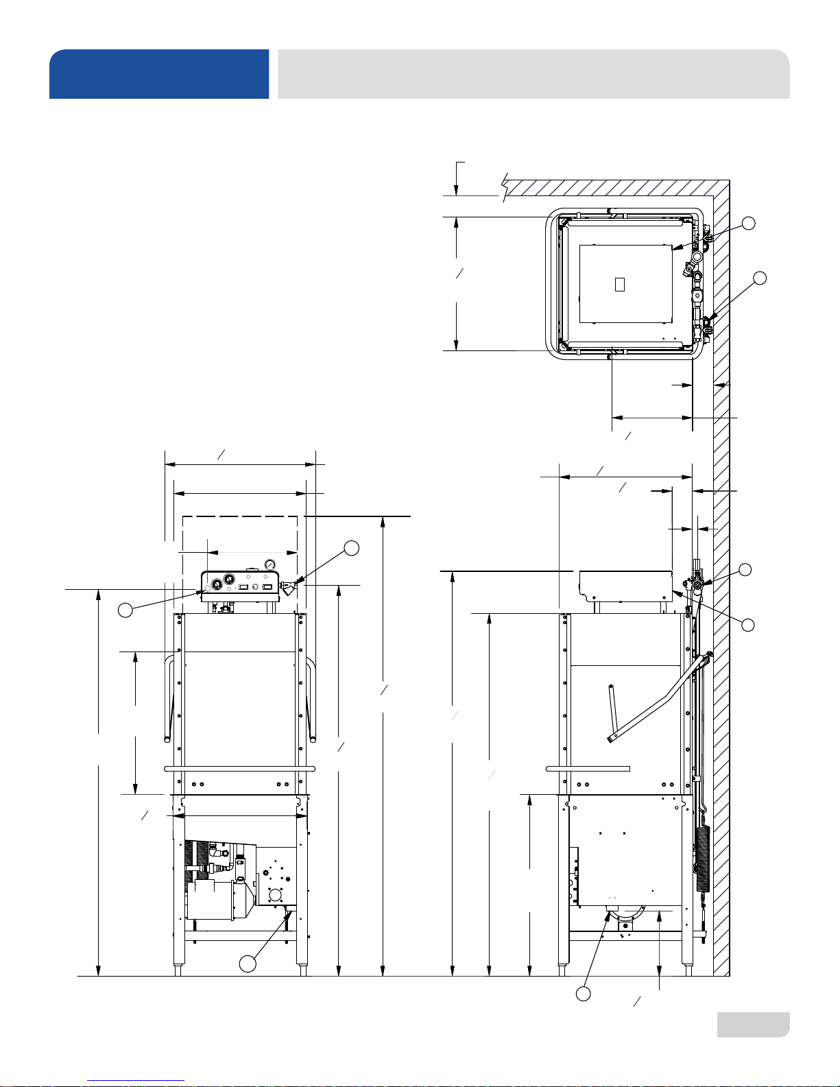
SPECIFICATIONS
LEGEND
A - Drain 1 1/2" NPT
B - Water Inlet 3/4" NPT
C - Electrical Connection
All dimensions from the oor can be
increased 2" using the machine's
adjustable feet.
MACHINE DIMENSIONS
07610-002-23-32-AC
2
Page 11
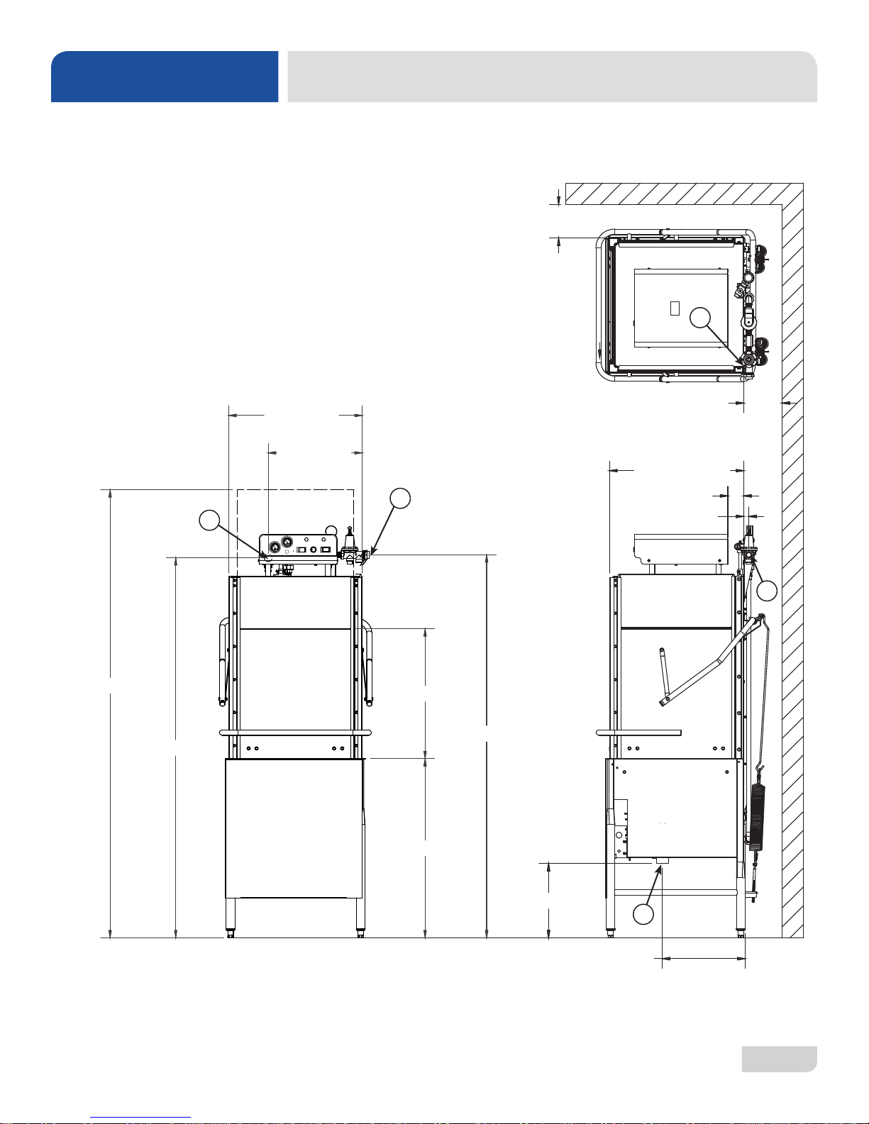
SPECIFICATIONS
DIMENSIONS - PRESSURE REGULATOR OPTION
LEGEND
A - Drain 1 1/2" NPT
B - Water Inlet 3/4" NPT
C - Electrical Connection
All dimensions from the oor can be
increased 2" using the machine's
adjustable feet.
4 [102mm]
B
86 3/4 [2203mm]
73 [1856mm]
25 [637mm]
17 [432mm]
B
C
27 [686mm]
73 1/4 [1873mm]
4 [102mm]
25 1/4 [641mm]
3 [76mm]
1 [25mm]
B
07610-002-23-32-AC
34 [861mm]
11 3/4 [298mm]
A
15 1/4 [387mm]
3
Page 12
4 [101mm]
[1873mm]
25 1/4 [639mm]
1 [25mm]
12 1/4 [310mm]
4 [102mm]
4 [102mm]
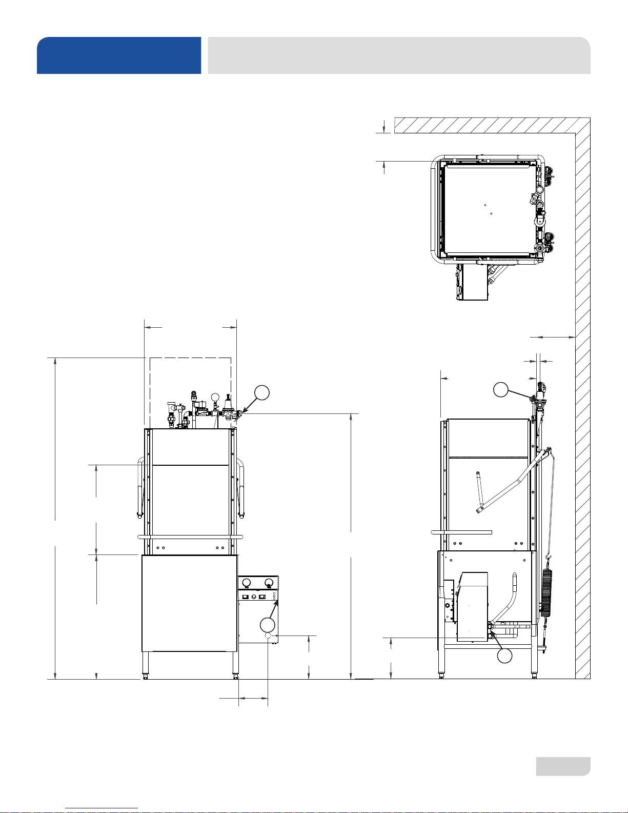
SPECIFICATIONS
DIMENSIONS - SIDE-MOUNT CONTROL BOX
LEGEND
A - Drain 1 1/2" NPT
B - Water Inlet 3/4" NPT
C - Electrical Connection
All dimensions from the oor can be
increased 2" using the machine's
adjustable feet.
LEGEND
A - DRAIN 1 1/2" IPS
B - WATER INLET 3/4" IPS
C - ELECTRICAL CONNECTION
All dimensions are in inches. All vertical
dimensions are +/- 1/2" due to adjustable
bullet feet.
25 [637mm]
4 [102mm]
4 [102mm]
1 [25mm]
25 1/4 [639mm]
B
B
27
[687]
34
[863mm]
7 1/2 [190mm]
C
12 3/4 [327mm]
73 3/4
A
07610-002-23-32-AC
4
Page 13
73 3/4
[1873mm]
25 [637mm]
25 1/4 [639mm]
86 1/4
[2156mm]
1 [25mm]
7 1/2 [190mm]
12 3/4 [327mm]
12 1/4 [310mm]
4 [102mm]
4 [102mm]
34
[863mm]
27
[687]
3 [76mm]
15 1/4
[388mm]
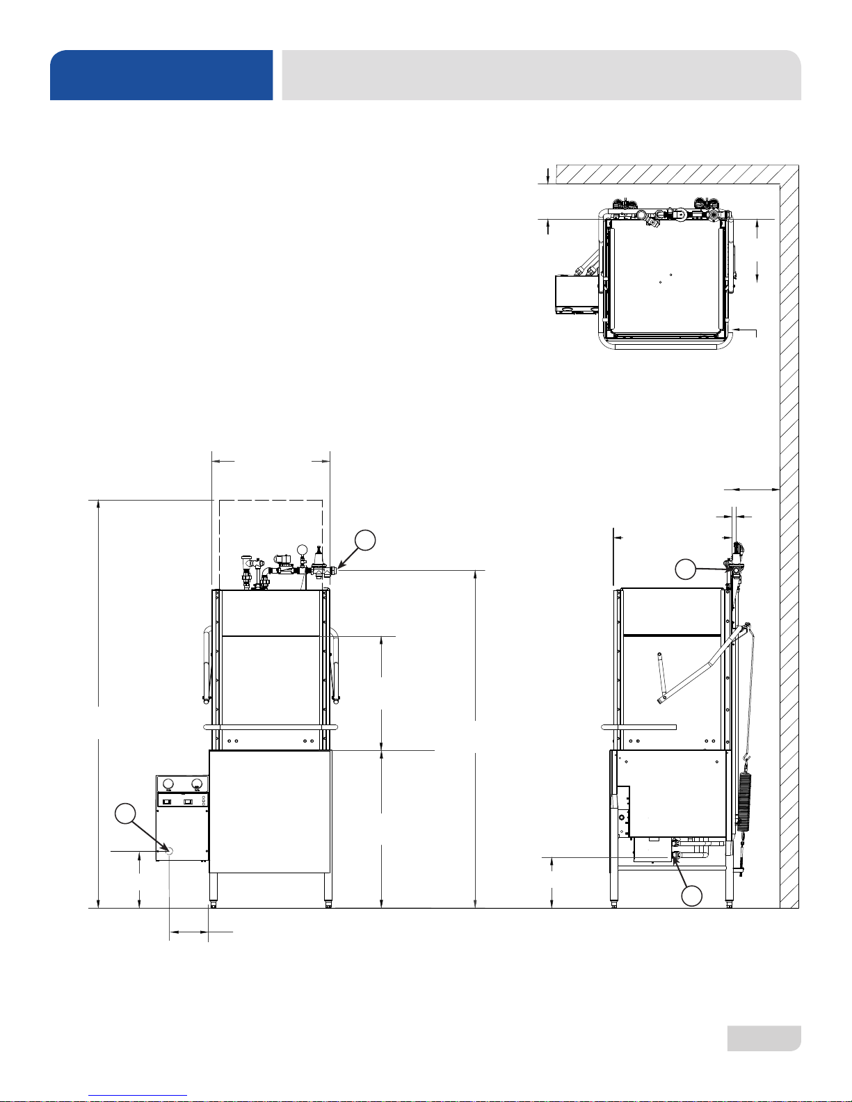
SPECIFICATIONS
LEGEND
A - Drain 1 1/2" NPT
B - Water Inlet 3/4" NPT
C - Electrical Connection
All dimensions from the oor can be
increased 2" using the machine's
adjustable feet.
DIMENSIONS - LEFT -SIDE CONTROL BOX
B
B
C
A
07610-002-23-32-AC
5
Page 14

25
1
4
(639mm)
2
3
4
(79mm)
17 (432mm)
25
1
4
(637mm)
73 (1856mm)
93 (2362mm)
(
)
LEGEND
A) DRAIN 1
1
2
IPS
B) WATER INLET
3
4
MIP
C) ELECTRICAL CONNECTIONS
All vertical dimensions are ± 1
/2" due to
adjustable bullet feet
B
88 (2235mm)
C
SPECIFICATIONS
LEGEND
A - Drain 1 1/2" NPT
B - Water Inlet 3/4" NPT
C - Electrical Connection
All dimensions from the oor can be
increased 2" using the machine's
adjustable feet.
1
25
(639mm)
B
4
DIMENSIONS - VENTLESS
101mm
3 (76mm)
1
5
(134mm)
4
B
1
25
(637mm)
4
17 (432mm)
4
88 (2235mm)
3
2
(79mm)
4
93 (2362mm)
73 (1856mm)
C
34 (861mm)
1
15
(387mm)
4
A
07610-002-23-32-AC
3
11
(298mm)
4
6
Page 15
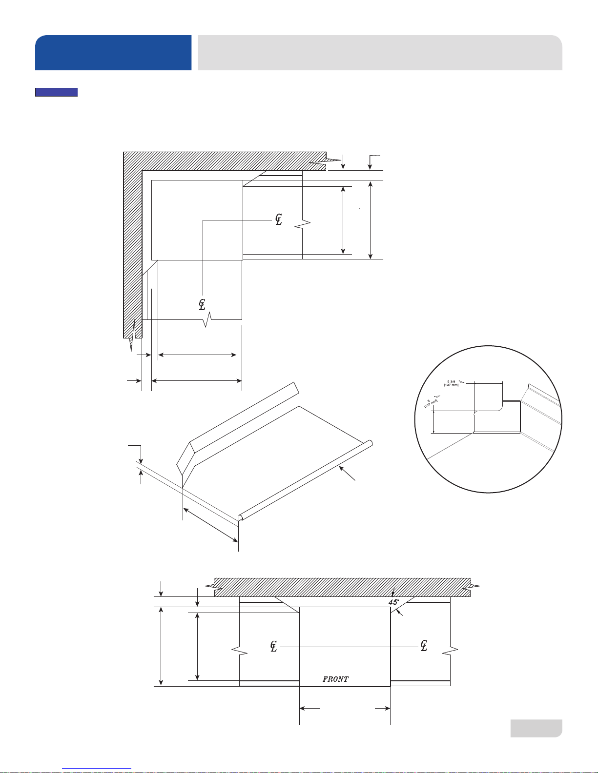
SPECIFICATIONS
NOTICE
Remove the front dress panel from the dishmachine if mounting the dishmachine in a corner
installation with side tables. Corner installation will trap the panel, making it difcult to remove.
2 1/2” (6.4 cm)
4” (10.2 cm)
MINIMUM
20 1/2” (52.1 cm)
OPENING
25 1/4”
(64.1 cm)
TABLE DIMENSIONS
4” (10.2 cm)
(6.4 cm)
2 1/2”
OPENING
20 1/2” (52.1 cm)
TABLE DIMENSIONS
CORNER INSTALLATION
25 1/4”
(64.1 cm)
MINIMUM
NOTCH DIMENSIONS
3/4” (1.9 cm)
07610-002-23-32-AC
20 1/2”
(52.1 cm)
4” (10.2 cm)
MINIMUM
25 1/4”
(64.1 cm)
2 1/2”
(6.4 cm)
OPENING
20 1/2” (52.1 cm)
TABLE DIMENSIONS
STRAIGHT THROUGH INSTALLATION
-
1 1/2” (3.81 cm) ROLL
TABLE DIMENSIONS
CONNECTION TO DISHMACHINE
25 1/4” (64.1 cm)
7
Page 16

SPECIFICATIONS
NOTICE
OPERATING PARAMETERS
OPERATING CAPACITY:
Normal Cycle
Racks per Hour 53
Dishes per Hour 1325
Glasses per Hour 1908
Medium Cycle
Racks per Hour 28
Dishes per Hour 700
Glasses per Hour 1008
Heavy Cycle
Racks per Hour 19
Dishes per Hour 475
Glasses per Hour 684
Extra-heavy Cycle
Racks per Hour 11
Dishes per Hour 275
Glasses per Hour 396
OPERATING CYCLES (SECONDS):
Wash Rinse Dwell Total
HH-E 40 10 10 60
Normal 45 15 2 62
Medium 103 15 2 120
Heavy 163 15 2 180
Extra-Heavy 283 15 2 300
Ventless:
Wash T ime 45
Rinse Time 15
Dwell Time 2
Condensate Removal 30
Total 92
Tank Capacity:
Rinse Tank (gallons/liters) 3.0/11.4
Wash Tank (gallons/liters) 8.0/30.3
WATER REQUIREMENTS:
TempStar HH & TempStar HH Ventless:
Wash Temperature (minimum) (°F/°C) 150/66
Rinse Temperature (minimum) (°F/°C) 180/83
Inlet Water Temperature:
12 kW Rinse Heater (°F/°C) 140/60
14 kW Rinse Heater (°F/°C) 110/44
14 kW Ventless (°F) 40-70
14 kW Ventless (°C) 4.4-21
Flow Pressure (PSI) 20±5
Water Line Size (NPT) 3/4"
Drain Line Size (NPT) 1 1/2"
TempStar HH-E:
Wash Temperature (minimum) (°F/°C) 155/68
Rinse Temperature (minimum) (°F/°C) 180/83
Inlet Water Temperature (°F/°C) 110/44
Flow Pressure (PSI) 10
Water Line Size (NPT) 1/2"
Drain Line Size (NPT) 1 1/2"
TempStar HH NB/Tempstar HH S:
Wash Temperature (minimum) (°F/°C) 150/66
Rinse Temperature (minimum) (°F/°C) 180/83
Inlet Water Temperature (°F/°C) 180/83
Flow Pressure (PSI) 20±5
Water Line Size (NPT) 3/4"
Drain Line Size (NPT) 1 1/2"
TempStar HH LT:
Wash Temperature (minimum) (°F/°C) 120/49
Rinse Temperature (minimum) (°F/°C) 120/49
Inlet Water Temperature (°F/°C) 120/49
Flow Pressure (PSI) 20±5
Water Line Size (NPT) 3/4"
Drain Line Size (NPT) 1 1/2"
STEAM REQUIREMENTS:
MOTOR HP:
Wash Motor HP 2.0
Always refer to the machine data plate for specic electrical and water requirements.
The material provided on this page is for reference only and is subject to change without notice.
i
07610-002-23-32-AC
Coil Size 3/4"
Steam Flow Pressure (PSI) 10-30
Consumption @ 15 PSI (lbs/hr) 45
8
Page 17

NOTICE
SPECIFICATIONS
Typical Electrical Circuit is based on:
1. 125% of the full amperage load of the machine.
i
Local codes may require more stringent protection than what is displayed here. Always verify with your electrical service
contractor that your circuit protection is adequate and meets all applicable national and local codes. Numbers in this manual
are for reference and may change without notice.
TEMPSTAR HH & HH-E:
Volts Phase Freq
415 3 60 Hz 12 kW 28 A 35 A
415 3 60 Hz 14 kW 30 A 40 A
208 1 60 Hz 12 kW@240 V 75 A 100 A
208 1 60 Hz 14 kW@240 V 82 A 110 A
230 1 60 Hz 12 kW@240 V 81 A 110 A
230 1 60 Hz 14 kW@240 V 90 A 125 A
208 3 60 Hz 12 kW@240 V 48 A 60 A
208 3 60 Hz 14 kW@240 V 52 A 70 A
230 3 60 Hz 12 kW@240 V 52 A 70 A
230 3 60 Hz 14 kW@240 V 57 A 80 A
460 3 60 Hz 12 kW@480 V 24 A 30 A
460 3 60 Hz 14 kW@480 V 26 A 35 A
TEMPSTAR HH VENTLESS:
Volts Phase Freq
208 1 60 Hz 15.4 kW 87 A 1 10 A
230 1 60 Hz 15.4 kW 96 A 125 A
208 3 60 Hz 15.4 kW 55 A 70 A
230 3 60 Hz 15.4 kW 61 A 80 A
460 3 60 Hz 15.4 kW 28 A 35 A
TEMPSTAR HH NB & TEMPSTAR HH LT:
Volts Phase Freq
208 1 60 Hz N/A 31 A 35 A
230 1 60 Hz N/A 33 A 35 A
208 3 60 Hz N/A 23 A 25 A
230 3 60 Hz N/A 24 A 35 A
460 3 60 Hz N/A 10 A 15 A
TEMPSTAR HH S:
Volts Phase Freq
208 1 60 Hz N/A 12 A 15 A
230 1 60 Hz N/A 12 A 15 A
208 3 60 Hz N/A 12 A 15 A
230 3 60 Hz N/A 12 A 15 A
2. Typical xed-trip circuit breaker sizes as listed in the NEC (latest edition).
ELECTRICAL REQUIREMENTS
Rinse Heater
Ratings
Rinse Heater
Ratings
Rinse Heater
Ratings
Rinse Heater
Ratings
T otal Amps
T otal Amps
T otal Amps
T otal Amps
Typical Electrical
Circuit
Typical Electrical
Circuit
Typical Electrical
Circuit
Typical Electrical
Circuit
07610-002-23-32-AC
9
Page 18

INSTALLATION
INSTRUCTIONS
INSPECTION
Do not throw away
packaging if damage is
evident!
UNPACKING
LEVELING
Before installing the unit, check the packaging and machine for damage. If the packaging
is damaged, the machine might also be damaged. If there is damage to both packaging
and machine, do not throw away the packaging. The dishmachine has been inspected
and packed at the factory and is expected to arrive to you in new, undamaged condition.
However, rough handling by carriers or others might result in damage to the unit while
in transit. If so, do not return the unit to the manufacturer. Instead, contact the carrier
and ask them to send a representative to the site to inspect the damage and complete
an inspection report. You must contact the carrier and the dealer that sold you the unit
within 48 hours of receiving the machine.
While removing the machine from the container, ensure that there are no missing parts.
If an item is missing, contact the manufacturer immediately .
The dishmachine must be level in its operating location to
prevent damage to the machine during operation and to
ensure the best results. The unit comes with four adjustable
bullet feet, which can be turned using a pair of channel locks
(or by hand if the unit can be raised safely). Ensure that
the unit is level from side-to-side and front-to-back before
making any connections.
Raise
Frame with Adjustable Foot
Lower
PLUMBING
The plumber MUST ush
the incoming water line!
A water hardness test
MUST be performed.
STEAM LINE
CONNECTION
Plumbing connections must comply with all applicable local, state, and national
plumbing codes. The plumber is responsible for ensuring that the incoming water line
is thoroughly ushed before connecting it to any component of the dishmachine. It is
very important to remove all foreign debris from the water line that might potentially get
trapped in the valves or cause an obstruction. Any valves that are fouled as a result of
foreign matter left in the water line—and any expenses resulting from this fouling—are
not the responsibility of the manufacturer.
A water hardness test must be performed to determine if the HTS-11 (scale
prevention and corrosion control) needs to be installed. If water hardness is higher
than 5 GPG, the HTS-11 will need to be installed. Please contact the manufacturer
to purchase the HTS-11.
The steam machines come with lines to connect the source steam. Connect all steam
lines to the machine as all applicable codes provide. See machine data plate for
information concerning steam ow pressure.
Click here for the Steam Booster manual.
07610-002-23-32-AC
10
Page 19

INSTALLATION
INSTRUCTIONS
WATER SUPPLY
CONNECTION:
WATER HARDNESS
GREATER THAN
5 GPG
WATER SUPPLY
CONNECTION:
WATER HARDNESS
OF 5 GPG OR LESS
PRESSURE
REGULATOR
Take care not to confuse
static pressure with
ow pressure.
If water hardness tests at greater than 5 GPG, install the HTS-11 into the water
line before the dishmachine’s incoming water connection point using copper pipe.
Observe proper inlet/outlet water directions. A water shut-off valve should be
installed to allow access for service. Plumb from the HTS-11 outlet to the incoming
water connection point using copper pipe (or order the exible hose kit offered by
the manufacturer).
If water hardness tests at 5 GPG or less, install the water supply line to the
dishmachine’s incoming water connection point using copper pipe (or order the
exible hose kit offered by the manufacturer). A water shut-off valve should be
installed to allow access for service.
The manufacturer recommends the installation of a water pressure regulator in the
incoming water line to ensure proper owrate at all times and offers these devices as
options. See the Plumbing Options page.
Do not confuse static pressure with ow pressure. Static pressure is the line pressure
in a “no ow” condition (all valves and services are closed). Flow pressure is the
pressure in the ll line when the ll valve is opened during the cycle.
SHOCK ABSORBER
CONNECTING THE
DRAIN LINE
The manufacturer also recommends the installation of a shock absorber in the
incoming water line and offers these devices as options. This prevents line hammer/
hydraulic shock—induced by the solenoid valve as it operates—from causing damage
to the equipment. See the Plumbing Options page.
The dishmachine's drain is a gravity-discharge drain. All piping from the 1 1/2” NPT
connection on the wash tank must be pitched (1/4” per foot) to the oor or sink drain.
All piping from the machine to the drain must be a minimum 1 1/2” NPT and must not
be reduced. There must also be an air-gap between the machine drain line and the
oor sink or drain. If a grease trap is required by code, it should have a ow capacity
of 5 GPM.
07610-002-23-32-AC
11
Page 20
INSTALLATION
INSTRUCTIONS
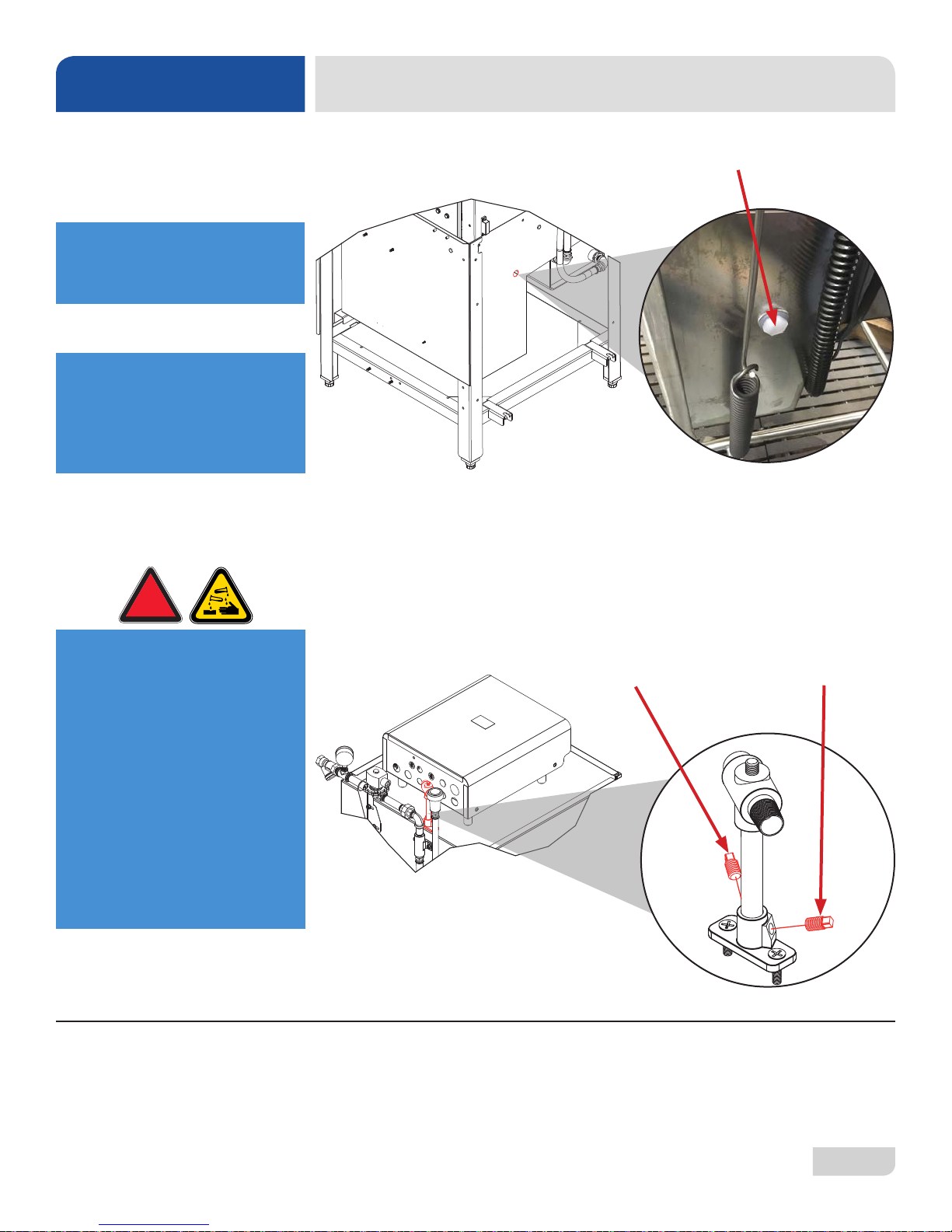
CHEMICAL
CONNECTIONS
Chemical connections
should be made by the
chemical supplier.
Using deionized water or
other aggressive uids
will result in corrosion and
failure of components and
will void the warranty.
!
WARNING
Detergent
Connect detergent by removing the bulkhead tting on the back of the machine and
replacing it with the appropriate dispensing equipment.
Rinse-aid and Sanitizer
Connect rinse-aid (and sanitizer, if an LT unit) by removing the brass plug at the base
of the rinse injector and replacing it with the appropriate dispensing equipment.
WARNING! Some of the
chemicals used in
dishwashing may cause
chemical burns if they
come in contact with skin.
Wear protective gear when
handling these chemicals.
If any skin comes in
contact with these
chemicals, immediately
follow the instructions
provided with the
chemicals for treatment.
PLUMBING CHECK
Sanitizer (LT Only) Rinse-aid
Slowly turn on the water supply to the machine after the incoming ll line and the drain
line have been installed. Check for any leaks and repair as required. All leaks must be
repaired before operating the machine.
07610-002-23-32-AC
12
Page 21

INSTALLATION
NOTICE
NOTICE
NOTICE
INSTRUCTIONS
ELECTRICAL POWER
CONNECTIONS
Disconnect electrical
power supplies and
lockout/tagout in
accordance with
appropriate procedures
and codes at the
disconnect switch.
Electrical and grounding conductors must comply with the applicable portions of the
National Electric Code ANSI/NFPA 70 (latest edition) and/or other electrical codes.
The data plate is located on the right side of the dishmachine. Refer to the data plate for
machine operating requirements, machine voltage, total amperage and serial number.
1. Open the control box by using a phillips screwdriver to remove the four screws on
the front cover of the control box.
2. Install 3/4” conduit into the pre-punched holes in the back of the control box.
3. Route power wires and connect to power block and grounding lug.
4. Install the service wires (L3 for 3-Phase only) to the appropriate terminals as they
are marked on the terminal block.
3Φ
Ground
L1
L2
L3
5. Install the grounding wire into the lug provided.
6. Tighten the connections.
Imbalanced
wild leg goes
to L3.
!
CAUTION
VOLT AGE CHECK
i
SURROUNDING AREA
It is recommended that “DE-OX” or similar anti-oxidation agent be used on
all power connections.
CAUTION! Improperly connecting external devices can cause damage to the
machine and/or electrical infrastructure! See Addendum for a wiring guide.
Ensure that the power button is in the off position and apply power to dishmachine.
Check the incoming power at the terminal block and ensure it corresponds with the
voltage listed on the data plate. If not, contact a qualied service agency to examine
the problem. Do not run dishmachine if voltage is too high or too low. Shut off the
service breaker and advise all proper personnel of the location of the breaker and
any problems. Replace the control box cover and tighten-down the screws.
This is a commercial dishmachine and reaches temperatures that can exceed
those generated by a residential machine. Surrounding countertops, cabinets, ooring
material, and suboor material must be designed and/or selected with these higher
temperatures in mind.
Any damage to surrounding area caused by heat/moisture to materials that
are not recommended for higher temperatures will not be covered under
warranty or by the manufacturer.
TEMPERATURE
SETPOINTS
07610-002-23-32-AC
The temperature setpoints on this unit have been set at the factory. They should
only be adjusted by an authorized service agent.
13
Page 22
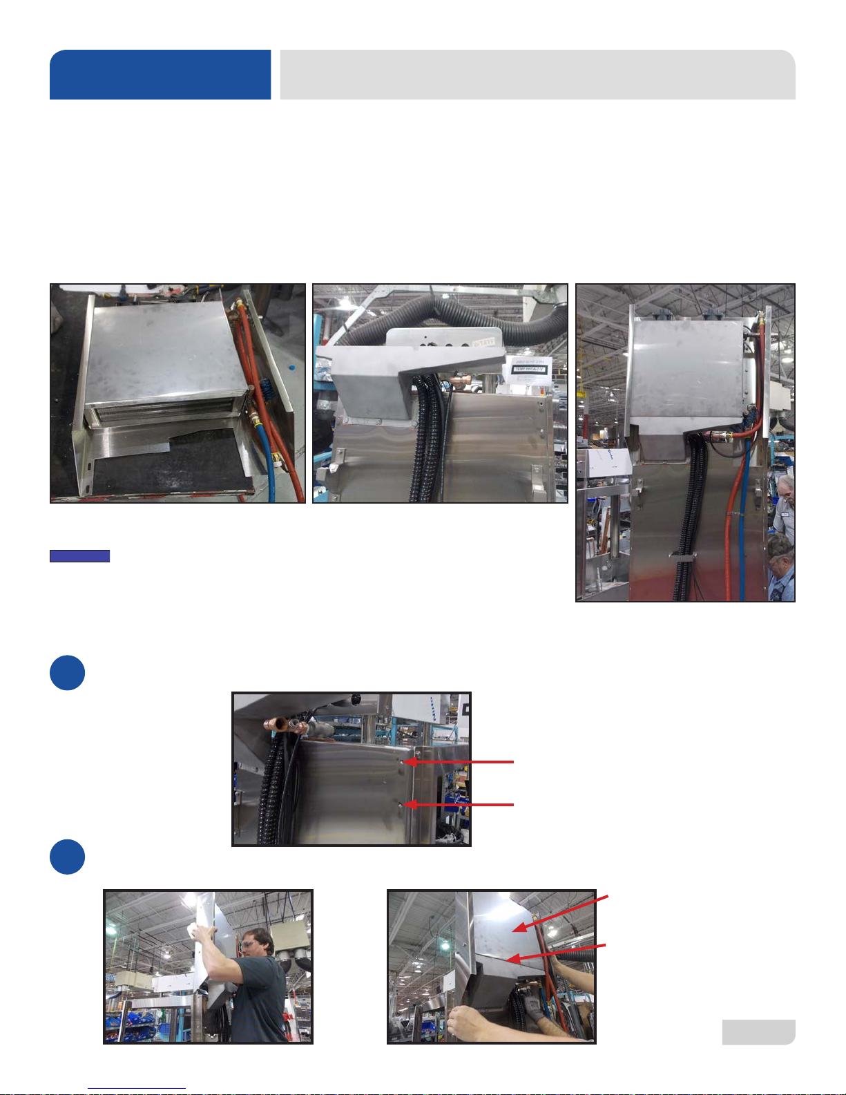
INSTALLATION
NOTICE
Due to shipping constraints, the Ventless/Energy Recovery assembly is not mounted by the manufacturer. These
instructions show how to mount the Ventless/Energy Recovery assembly onto the Ventless machine.
VENTLESS MOUNTING INSTRUCTIONS
TOOLS REQUIRED:
• 7/16” Wrench
• 9/16” Wrench
• Adjustable Wrench
Ventless/Energy Recovery Unit
The Ventless/Energy Recovery assembly is packaged with the machine
but not mounted.
INSTRUCTIONS:
Base Unit Fully-assembled Unit
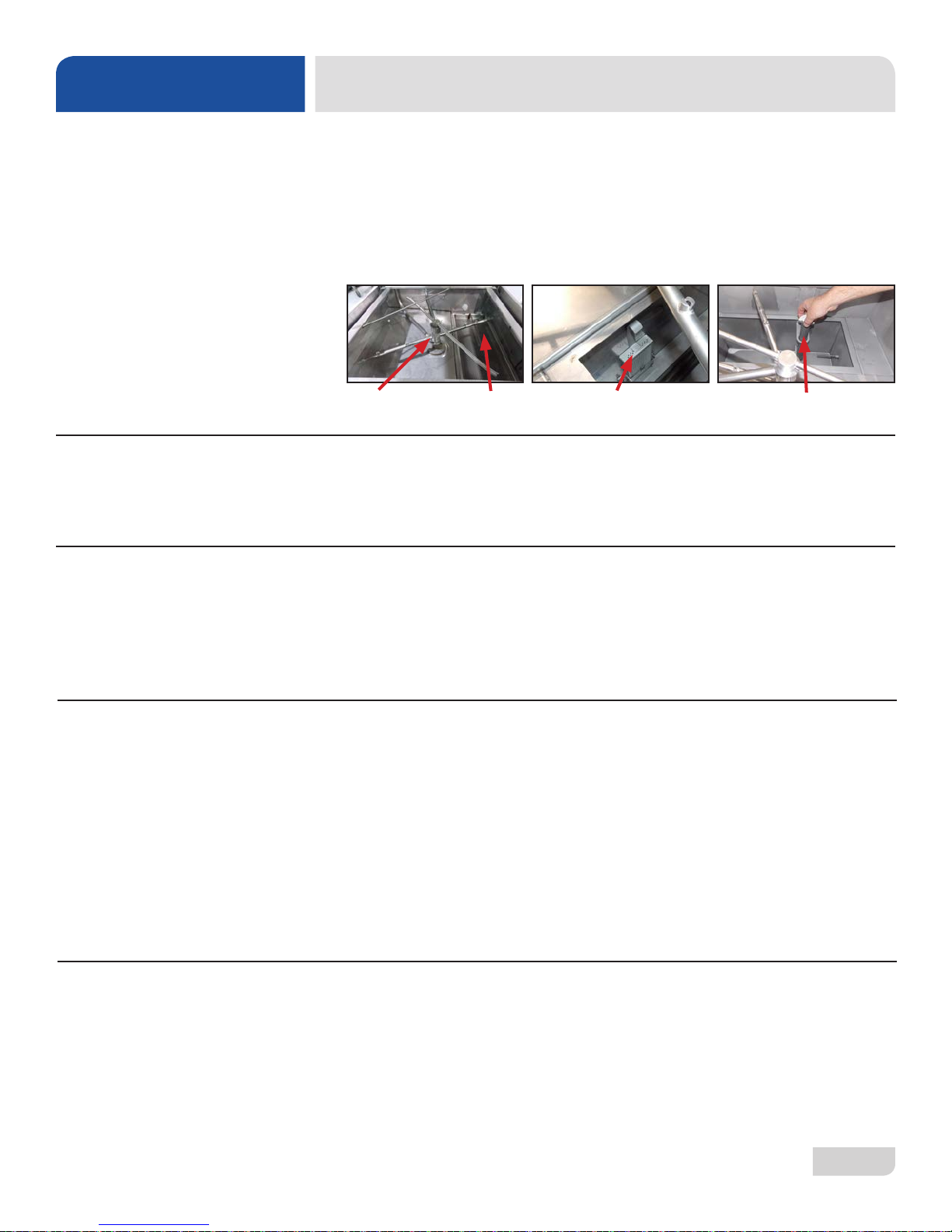
Locate and remove the four 1/4-20 bolts using a 7/16 wrench. These are located in the top-left and right corner of the
1
unit.
Lift the Ventless/Energy Recovery unit up and over the lower air inlet, then align and slide unit onto the lower air inlet.
2
Upper unit should slide inside the lower air inlet at the seam.
Ventless/Energy Recovery Unit
Lower Air Inlet Seam
07610-002-23-32-AC
14
Page 23
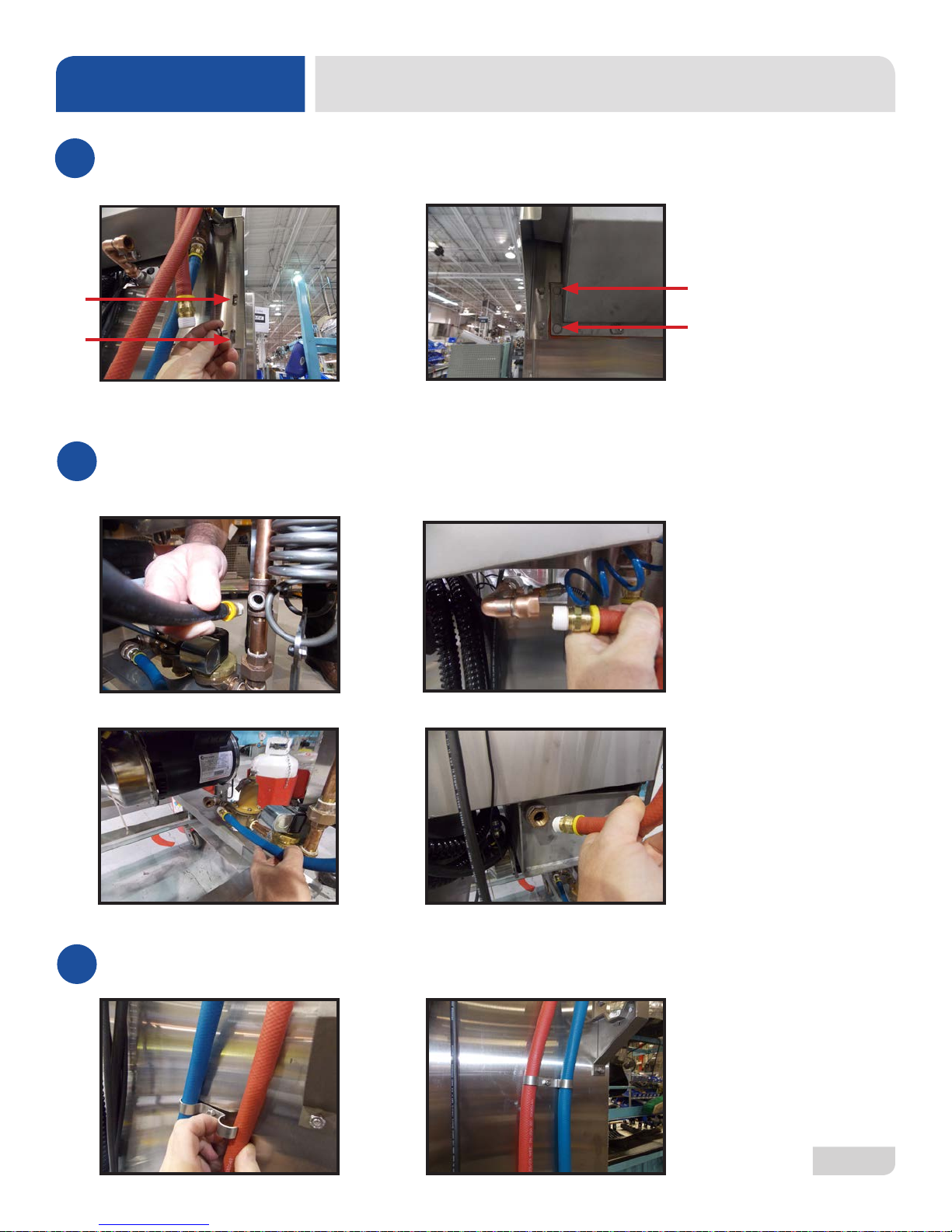
INSTALLATION
Reinstall the four 1/4-20 bolts that were removed in step 1 with a 7/16 wrench. They insert into the machine on the
3
right and left corners.
Connect pressure gauge with a 9/16 wrench. Connect the two hoses using an adustable wrench. The hoses are cut-
4
to-length and will only reach their intended connection point.
A. Connect the Gauge B. Final Rinse Inlet
VENTLESS MOUNTING INSTRUCTIONS
C. PRV Inlet from Coil D. Booster Outlet
Before moving to the next step, tidy up the hoses by sliding them under the clamps. You might need to loosen the nut
5
to accomplish this.
07610-002-23-32-AC
15
Page 24

INSTALLATION
Locate the wire connectors at the top of the unit and connect the white and black wires from the base unit.
6
Tidy up the wires and lock them in place with the P-Clamp on top of the unit.
7
VENTLESS MOUNTING INSTRUCTIONS
Slide wire into the hole and push the lever down.
P-Clamp
You now have a fully-assembled unit.
8
07610-002-23-32-AC
16
Page 25

INSTALLATION
PROGRAMMING EXHAUST FAN TIMER
1. Apply power (120, 208, or 240 VAC) to the A1 & A2 terminals.
Timer Wiring with Correct Wire Colors
Light Gray
Dark Gray
Red/Yellow
Yellow/Black
2. Hold down the SET and ADJ buttons for at least three seconds.
Yellow
Red
3. Repeatedly press the ADJ button until the letter E appears on the left-hand side.
4. Press the SET button.
5. Press the ADJ button until the letters M S appear.
6. Press the SET button.
7. Press the ADJ button to adjust the rst digit to 2.
8. Press the SET button.
9. Press the ADJ button to adjust the second digit to 3.
10. Press the SET button.
11. Press the ADJ button to adjust the third digit to 0.
12. Press the SET button.
13. Press the ADJ button so there is an arrow facing downward.
14. Press the SET button.
07610-002-23-32-AC
17
Page 26

NOTICE
INSTALLATION
STEP ACTION RESULT
1. Apply power (120, 208, or 240 VAC) to the A1 & A2 terminals. Idle state.
TESTING EXHAUST FAN TIMER
2. Make control signal connection at B1. No control signal is
applied.
3. Apply control signal (logic high). Relay closes (ports 15-18).
4. Remove control signal (logic low). Relay remains closed for 2.5 minutes.
In Step 4, if control signal is reapplied while the relay is still closed, Step 3 will restart.
Remains in idle state.
07610-002-23-32-AC
18
Page 27

INSTALLATION
FALSE PANEL INSTRUCTIONS
Rack rail removed and
repositioned for a
corner operation.
07610-002-23-32-AC
False Panel Positioned in Unit
1. Remove the rack assembly from the dishmachine.
2. The false panel will mount inside of the dishmachine.
3. Position the panel in the dishmachine on the side to be closed.
4. Hold the panel against the side of the dishmachine and push upward.
5. The panel will clip in at the top, inside of the unit.
6. The holes in the false panel will line-up with the rack assembly holes.
7. Reinstall the screws for the rack assembly which will secure
the false panel to the unit.
8. Reassemble the rack track in an "L" shape for a corner operation.
19
Page 28
OPERATION
OPERATING INSTRUCTIONS
PREPARATION
POWER UP
FILLING THE
WASH TUB
Before operating the unit, verify the following:
1. The tank is clean and free of debris.
2. The wash arms, rinse arms, sump strainer, and scrap screen are all installed
correctly.
3. The standpipe is installed.
Wash & Rinse Arms, Scrap Screen
To energize the unit, turn on the power at the service breaker. The voltage should
have been previously veried as being correct. If not, the voltage will have to be
veried.
Ensure that the mode switch is in the "AUTO" position, and place the power switch into
the "ON" position. The machine will ll automatically and shut-off when the appropriate
level is reached (just below the scrap screen). The wash tub must be completely lled
before operating the wash pump to prevent damage to the component. Once the
wash tub is lled, the unit is ready for operation.
Sump Strainer
Standpipe
PREPARATION
DAILY MACHINE
PREPARATION
07610-002-23-32-AC
WARE
Proper preparation of ware will help ensure good results and fewer re-washes.
If not prepared properly, ware might not come out clean and the efciency of the
dishmachine will be reduced. Putting unscraped dishes into the machine affects its
performance, so scraps should always be removed from ware before being loaded
into a rack. Pre-rinsing and pre-soaking are good ideas, especially for silverware and
casserole dishes.
Place cups and glasses upside-down in racks so they don't hold water during the
cycle. The dishmachine sanitizes as well as cleans. To do this, ware must be properly
prepared before being placed in the machine.
Refer to the “Preparation” section and follow the instructions there. Afterward, ensure
that chemicals are supplied to the machine. If not, contact your chemical supplier.
20
Page 29

OPERATION
OPERATING INSTRUCTIONS
WARM-UP CYCLES
W ASHING A RACK
OF WARE
OPERATIONAL
INSPECTION
For the rst operation of each day, it might be necessary to run the machine through
three cycles to ensure that all of the cold water is out of the system and to verify that
the unit is operating correctly. To cycle the machine, ensure that the power is on and
that the tub has lled to the correct level. Lift the door and the cycle light will illuminate.
When the light goes out, close the door, the unit will start, run through the cycle, and
shut-off automatically. Repeat this two more times. The unit should now be ready to
proceed with the washing of ware.
To wash a rack, open the door completely (avoiding hot water that might drip from
the door) and slide the rack into the unit.
Close the door and the unit will start automatically. Once the cycle is complete,
open the door (again watching for the dripping hot water) and remove the rack of
clean ware. Replace with a rack of soiled ware and close the door. The process will
repeat itself.
Based upon usage, the scrap screen might become clogged with soil and debris
as the workday progresses. Operators should regularly inspect the scrap screen to
ensure it has not become clogged. If clogged, it will reduce the washing capability of
the machine. Instruct operators to clean-out the scrap screen at regular intervals or
as required by workload.
SHUTDOWN &
CLEANING
!
WARNING
1. Turn machine off by flipping the “Power On/Power Off” switch to “OFF.”
2. Open the door and allow steam/heat to escape.
3. Remove the standpipe and allow the tub to drain.
WARNING! Wash tank water will be hot!
07610-002-23-32-AC
21
Page 30

OPERATION
OPERATING INSTRUCTIONS
SHUTDOWN &
CLEANING
4. Remove the sump strainer and scrap screen.
5. Use a hand-scraper to scrape foodsoil into a trash basket.
6. Rinse with pre-rinse hose and replace.
07610-002-23-32-AC
7. Remove all wash and rinse arms.
8. Remove the end-caps from the arms.
9. Clean nozzles with a brush.
22
Page 31

OPERATION
OPERATING INSTRUCTIONS
SHUTDOWN &
CLEANING
10. Use a small wire or toothpick to remove remaining debris or lime deposits from
the nozzles.
11. Flush the arms with water.
12. Replace end-caps and ensure they have been tightened.
13. Spray or wipe out interior of the machine.
14. Replace wash and rinse arms.
15. Ensure sump strainer and scrap screen are clean and securely in place.
16. Use stainless steel polish to clean and protect outside of dishmachine.
07610-002-23-32-AC
23
Page 32

OPERATION
DETERGENT CONTROL
DETERGENT
CONTROL
Detergent usage and water hardness are two factors that contribute greatly to how
efciently this dishmachine will operate. Using detergent in the proper amount can
become a source of substantial savings. A qualied water treatment specialist can
determine what is needed for maximum efciency from the detergent.
1. Hard water greatly affects the performance of the dishmachine, causing the
amount of detergent required for washing to increase. If the machine is installed
in an area with hard water, the manufacturer recommends the installation of
water treatment equipment.
2. Deposited solids from hard water can cause spotting that will not be removed
with a drying agent. Treated water will reduce this occurence.
3. Treated water might not be suitable for use in other areas of operation and it
might be necessary to install a water treatment unit for the water going to the
dishmachine only. Discuss this option with a qualied water treatment specialist.
4. Dishmachine operators should be properly trained on how much detergent is to
be used per cycle. Meet with a water treatment specialist and detergent vendor
to discuss a complete training program for operators.
5. These dishmachines require that chemicals be provided for proper operation
and sanitization and require the installation of third-party chemical feeders to
introduce these chemicals to the machine. Contact a chemical supplier with any
questions.
6. Water temperature is an important factor in ensuring that the dishmachine
functions properly. The machine's data plate details what the minimum
temperatures must be for the incoming water supply, the wash tank, and the
rinse tank. If minimum requirements are not met, there is a possibility that dishes
will not be clean or sanitized.
7. Instruct dishmachine operators to observe the required temperatures and to
report when they fall below the minimum allowed. A loss of temperature can
indicate a larger problem.
07610-002-23-32-AC
24
Page 33

OPERATION
DELIME INSTRUCTIONS
DELIMING
To delime the machine, follow the steps below. The tank capacities of the machine
can be found in the Specications section of this manual.
1. Remove rinse arms and place in sink with deliming solution.
2. Disconnect or turn off chemical feeder pumps.
3. Add deliming solution per chemical supplier’s instructions.
4. Close the door and turn the machine on in "MANUAL" mode.
5. Run the machine for the length of time recommended by the chemical supplier.
6. Flip the mode switch to "AUTO" to shut the unit off.
7. Open the door and step away for ve minutes.
8. Inspect the inside of the machine. If the machine is not delimed, run again.
9. When clean, drain and re-ll the machine.
10. Run two cycles in "AUTO" to remove residual deliming solution.
11. Drain and re-ll the machine.
12. Flush rinse arms with water and replace.
Mode Switch
07610-002-23-32-AC
!
CAUTION
Power Switch
CAUTION! This equipment is not recommended for use with deionized water or other
aggressive uids. Use of deionized water or other aggressive uids will result in corrosion and
failure of materials and components. Use of deionized water or other aggressive uids will
void the manufacturer’s warranty.
25
Page 34

MAINTENANCE
PREVENTATIVE MAINTENANCE
PREVENTATIVE
MAINTENANCE
i
The manufacturer highly recommends that any maintenance and repairs not specically
discussed in this manual be performed only by qualied service personnel. Performing
maintenance on your dishmachine may void your warranty, lead to larger problems, or
even cause harm to the operator.
By following the operating and cleaning instructions in this manual, you should get the
most efcient results from your machine. As a reminder, here are some steps to take to
ensure that you are using the dishmachine the way it was designed to work:
1. Ensure that the water temperatures match those listed on the machine data plate.
There can be a variety of reasons why your water temperature could be too low.
2. Ensure that all strainers are clean and securely in place before operating the machine.
When cleaning out strainers, do NOT beat them on waste cans. Wipe-out strainers
with a rag and rinse under a faucet if necessary. Use a toothpick to dislodge any
stubborn debris.
3. Ensure that all wash and rinse arms are secure in the machine before operating.
4. Ensure that the standpipe is seated in the sump before operating.
5. Remove as much soil from dishes by hand as possible before loading into racks.
6. Do not overll racks.
7. Ensure that glasses are placed upside-down in the rack.
8. Ensure that all chemicals being injected into machine have been veried at the
correct concentrations.
9. Clean-out the machine at the end of every workday per the Shutdown and Cleaning
section of this manual.
10. Follow all safety procedures, whether listed in this manual or put forth by local, state,
or national codes/regulations.
07610-002-23-32-AC
26
Page 35

MAINTENANCE
RINSE ARM MAINTENANCE
BEARING
REPLACEMENT
Disconnect electrical
power supplies and
lockout/tagout in
accordance with
appropriate procedures
and codes at the
disconnect switch.
06401-004-33-51
RINSE ARM BEARING KIT
• 1 Bearing
03120-004-12-13
• 1 Retaining Clip
05340-112-01-11
• 2 Washers
05330-011-42-10
1. Unscrew the rinse arm from the manifold.
2. Take the retaining clip off with a flathead screwdriver.
3. Remove the first washer.
4. Remove the rinse head bushing.
TOOLS REQUIRED
• Flathead Screwdriver
5. Remove the bearing.
6. Remove the second washer.
07610-002-23-32-AC
27
Page 36

MAINTENANCE
RINSE ARM MAINTENANCE
BEARING
REPLACEMENT
One of the washers from
the kit is used in this step.
The bearing from the kit is
used in this step.
7. Place one of the washers from the kit on the rinse arm.
8. Put the bearing from the kit on top of the washer.
9. Place the rinse head bushing back on the rinse arm.
One of the washers from
the kit is used in this step.
The retaining clip from the
kit is used in this step.
!
CAUTION
10. Put the other washer from the kit on top of the rinse head bushing.
11. Push the retaining clip from the kit into place.
12. Screw the rinse arm back on the manifold.
CAUTION! Work performed on dishmachines by unauthorized or unqualified
personnel may void the warranty. Before beginning this or any other maintenance
on a unit under warranty, you should contact a qualified service agency.
07610-002-23-32-AC
28
Page 37

TROUBLESHOOTING
WARNING! Inspection, testing, and repair of electrical equipment should only be performed by a
!
WARNING
PROBLEM POSSIBLE CAUSE REMEDY
Dishmachine runs
continuously in the
wash cycle.
qualied service technician. Many of the tests require that the unit have power to it and live electrical
components be exposed. USE EXTREME CAUTION WHEN TESTING THE MACHINE.
Machine is in manual (delime)
mode.
Wash cycle delay timer is faulty.
Change operation mode from MANUAL to AUTO position.
During the wash cycle, the cam timer will move for the rst 30 seconds
of the wash cycle. The cycle delay timer will then cause the cam timer to
stop in order to increase the length of the wash cycle. The red light on
the delay timer is in control of the cam timer. If the red light is not turning
on (only during cycles B, C, or D), replace the cycle timer.
COMMON PROBLEMS
Dishmachine will not
ll after the door is
closed. Power "ON"
light is illuminated.
Dishmachine will not
ll after the door is
closed. Power "ON"
light is not illuminated.
Dishmachine will not
ll after the door is
closed. Power "ON"
light is not illuminated.
Wash cycle delay timer settings are
not correctly adjusted.
Cam timer is faulty.
Faulty rinse solenoid valve.
Faulty door switch.
Fouled/faulty high-level probe.
Service breaker tripped.
Machine not connected to power
source.
Faulty power source.
Service breaker tripped.
Machine not connected to power
source.
If the wash cycle delay timer and rotating cam timer are working correctly,
the time cycles on the delay timer might be incorrectly adjusted. Adjust
the delay potentiometer corresponding to the B, C, or D cycle. Rerun
the appropriate cycle and see if the adjustment made any change in the
length of the cycle. If not, replace the cycle delay timer.
Conrm that the wash cycle delay timer is functioning correctly (see
above). Conrm that the timer motor is receiving power. If it is, replace
the motor and/or timer assembly. Make sure there are no obstructions
which limit the rotation of the cam timer.
Repair or replace valve as required.
Verify the wiring of the switch; if correct, replace the switch.
Clean probe if fouled. If clean and not working, replace.
Reset. If the breaker trips again, contact an electrician to verify the amp
draw of the machine.
Verify that the machine has been properly connected to the power
source.
Verify the wiring of the switch; if correct, replace switch.
Reset. If the breaker trips again, contact an electrician to verify the amp
draw of the machine.
Verify that the machine has been properly connected to the power
source.
Faulty power source.
Wash or rinse heater
does not work.
07610-002-23-32-AC
Faulty heater element.
Faulty heater contactor.
Mis-adjusted/faulty thermostat(s).
Verify the wiring of the switch; if correct, replace switch.
Check element for continuity; if open, replace the heater.
Replace the contactor.
Verify the operation and setting of thermostats; replace if necessary.
29
Page 38

TROUBLESHOOTING
WARNING! Inspection, testing, and repair of electrical equipment should only be performed by a
!
WARNING
PROBLEM POSSIBLE CAUSE REMEDY
Dishmachine lls
slowly and/or rinse is
weak.
qualied service technician. Many of the tests require that the unit have power to it and live electrical
components be exposed. USE EXTREME CAUTION WHEN TESTING THE MACHINE.
Clogged or obstructed rinse arms.
Low incoming water pressure.
Remove and clean the rinse arms.
Adjust the water pressure regulator (not supplied) to ensure the ow
pressure matches the data plate.
COMMON PROBLEMS
Rinse water is not
reaching required
temperature.
Wash water is not
reaching required
temperature.
Doors will not close
completely.
Water leaks at the
wash pump.
Will not rinse during
auto-cycle.
Y-strainer is clogged.
Faulty rinse heater.
Mis-adjusted/faulty thermostat(s).
Rinse thermometer is defective.
Faulty wash heater.
Mis-adjusted/faulty thermostat(s).
Wash thermometer is defective.
Improper spring tension.
Obstruction in door channel.
Doors are not square with frame.
Wash pump seal defective.
Petcock or pump drain (if
equipped) not shut/tight.
Loose hoses (hose clamps) on the
wash pump.
Defective rinse solenoid.
Faulty ll microswitch.
Clean out the Y-strainer.
Check element for continuity; if open, replace heater.
Verify operation and setting of thermostats; replace if necessary.
Replace thermometer.
Check element for continuity; if open, replace heater.
Verify operation and setting of thermostats; replace if necessary.
Replace thermometer.
Adjust spring tension as required by loosening (not removing) spring bolt
nuts and adjusting the tension. Tighten nuts back when done.
Remove the obstruction.
Adjust the frame to accommodate the doors.
Replace the seal.
Close or tighten.
Tighten the hose clamps.
Repair or replace the rinse solenoid as required.
Replace microswitch.
No water to the machine.
Dishes are not
coming clean.
07610-002-23-32-AC
Machine temperatures are not up
to the minimum requirements.
No detergent/too much detergent.
Solid dispenser canister is empty.
Verify that the ow pressure matches the data plate.
Verify that incoming water, rinse water, and wash water match the re-
quired temperatures as listed on the machine data plate.
Adjust detergent concentration as required for the amount of water held
by the machine.
Replace the canister.
30
Page 39

PARTS
26
TOP-MOUNT CONTROL BOX
30
36
34
33
1
25
28
29
22
07610-002-23-32-AC
21
31
Page 40

PARTS
32
TOP-MOUNT CONTROL BOX
16
31
5
6
7
6
66
6423
24
37
39
2
6
8
1114
1215
9 10
17
18
20
6
27
07610-002-23-32-AC
13
424041
32
Page 41

PARTS
TOP-MOUNT CONTROL BOX
ITEM QTY DESCRIPTION PART NUMBER
1 1 Control Box Weldment 05700-003-30-14
2 1 Timer Bracket 05700-003-02-08
3 2 Locknut, 6-32 (Not Shown) 05310-373-03-00
4* 2 Heater Contactor 05945-109-01-69
5 1 Terminal Block 05940-011-48-27
6 17 Locknut, 10-24 05310-373-01-00
7 1 Contactor, Wash Motor 05945-002-74-20
8
9 1 Light, Green 05945-111-44-43
10 1 Light, Red 05945-111-44-45
11 1 Temperature Gauge, Wash 96" Lead 06685-004-17-27
12 1 Temperature Gauge, Rinse 48" Lead 06685-111-68-48
13 1 Light, Yellow 05945-111-44-44
14 1 Decal, Wash 150 °F Min 09905-002-97-61
15 1 Decal, Rinse 180 °F Min 09905-002-97-62
16 1 Ground Lug 05940-200-76-00
17 1 Bracket, Liquid Level Control Board 05700-002-13-22
18 1 Liquid Level Control Board 06680-200-08-21
19 6 Tricnut, 6-32 05340-118-04-00
20 3 Screw, 6-32 x 5/8" 05305-011-39-85
21 3 Plug, 1/2" 05975-011-47-81
22 2 Grommet, 7/8" Split 05975-200-40-00
1 Relay 05945-111-47-74
1 Relay (460 V, 3-Phase, 5-Wire Only) 05945-111-89-75
23 1 Bushing Snap 05975-210-05-00
24 1 Clamp, Hose .25 - .312 05975-002-61-43
25 1 Decal, Warning-Disconnect Power 09905-004-08-16
26 1 Cover, Top-mount Control Box 05700-002-23-03
27 1 Decal, Control Box 09905-003-97-36
28 4 Lockwasher, Int. Tooth #10 05311-273-03-00
29 4 Screw, 10-32 x 3/8" 05305-173-12-00
30 1 Decal, Copper Conductors 09905-011-47-35
31 1 Decal, Ground 09905-011-86-86
32 1 Decal, L1, L2, L3 09905-101-12-66
33 1 Bracket, Fuse Strip 05700-002-42-03
07610-002-23-32-AC
33
Page 42

PARTS
TOP-MOUNT CONTROL BOX
ITEM QTY DESCRIPTION PART NUMBER
34 1 Fuse Holder, 6-Pole (Not Shown) 05920-002-42-13
35 2 Screw, 6-32 x 3/8" with Tooth Washer (Not Shown) 05305-002-25-91
36
37 1 Timer, Universal 05945-003-75-23
38 4 Locknut, 10-32 (Not Shown) 05310-373-02-00
39 4 Screw 10-32 x 1" (Not Shown) 05305-002-19-42
40 1 Switch, Rotary Selector 05930-003-97-61
41 1 Switch, Operation 05930-301-53-00
42 1 Switch, Power 05930-011-49-55
43* 1 Overload, TK-ONY (460 V Unit Only) 05945-002-65-02
44* 1 Motor Contactor, SC-03Y (460 V Unit Only) 05945-002-65-00
45* 1 Din Rail, 2 3/4" (460 V Unit Only) 05700-001-84-65
*For a 460 V Unit, replace item 4 with items 43, 44 & 45.
1 Decal, Dispenser Connection (Not Shown) 09905-003-34-09
1 Decal, Dispenser Connection (460 V Unit Only) (Not Shown) 09905-004-43-81
07610-002-23-32-AC
34
Page 43

PARTS
SIDE-MOUNT CONTROL BOX
1
2
3
1010
9
7
5
12
13
14
15
2829
4
1
26
27
36
30
31
10
32
18
19
20
2421
07610-002-23-32-AC
21
22
23
24
11
35
Page 44

PARTS
SIDE-MOUNT CONTROL BOX
ITEM QTY DESCRIPTION PART NUMBER
1 1 Bracket, Electrical Box Mounting 05700-002-18-48
2 9 Locknut, 1/4-20 Hex with Nylon Insert 05310-374-01-00
3 9 Washer, 1/4-20 ID 05311-174-01-00
4
5
6 4 Screw, 10-32 x 1/2" 05305-002-32-37
7 1 Liquid Level Control 06680-200-08-21
8 3 Screw, 6-32 x 5/8" 05305-011-39-85
9 1 Thermometer, 48 Lead, Wash 06685-111-68-48
9a 1 Decal, Wash 150 °F 09905-002-97-61
9b 1 Decal, 120 °F Wash/Rinse (Not Shown) (LT Only) 09905-002-82-46
10 1 Relay, 240 V, 50/60 Hz, Top-Mount 05945-002-47-74
11 8 Screw, 6-32 x 3/8" SEMS with Tooth Washer 05305-002-25-91
12 1 Decal, Control Box Gauge 09905-002-10-69
13 1 Thermometer, 96 Lead, Rinse 06685-111-68-49
13a 1 Decal, Rinse 180 °F 09905-002-97-62
13b 1 Decal, 120 °F Wash/Rinse (Not Shown) (LT Only) 09905-002-82-46
14 1 Timer, Universal 05945-003-75-23
1 Control Box Weldment, Right-hand 05700-002-06-48
1 Control Box Weldment, Left-hand 05700-002-23-08
2
1
Contactor, 4-Pole, 220 V, 1-Phase
No Booster, Steam Models, and LT
05945-109-01-69
15 1 Timer, Bracket 05700-002-98-21
15a 6 Holder, Keystone 05940-002-21-87
15b 1 Keying Plug 05940-003-11-66
15c 2 Connector 05940-003-11-65
16 1 Contactor, 2-Pole, 220 V, 20 A (208-230 V Unit Only) 05945-002-74-20
17 1
18 1 Terminal Block, 3-Pole 05940-011-48-27
19 1 Decal, L1, L2, L3 09905-101-12-66
20 1 Decal, Copper Conductors 09905-011-47-35
21 4 Locknut, 10-24 Hex with Nylon Insert 05310-373-01-00
22 1 Wire Lug 05940-200-76-00
23 1 Decal, Ground 09905-011-86-86
24 1 Holder, Fuse 05920-401-03-14
07610-002-23-32-AC
Timer, Cycle Delay (not used with Universal Timer or LT) (Not
Shown)
05945-002-13-78
36
Page 45

PARTS
SIDE-MOUNT CONTROL BOX
ITEM QTY DESCRIPTION PART NUMBER
25
26 4 Bolt, 10-32 x 1/2" Slotted Truss 05305-173-04-00
27 1 Switch, Rotary Selector (Not on LT) 05930-003-97-61
28 1 Switch, Operation 05930-301-53-00
1 Cover, Control Box Weldment 05700-002-06-51
Cover, Control Box Weldment (Not Shown) (LT Only) 05700-004-22-50
29
30 1 Light, Red 05945-504-07-18
31 1 Light, Green Indicator 05945-504-08-18
32 1 Light, Amber 05945-504-06-18
33 1 Cover, Dielectric Control Panel (Not Shown) 05700-021-50-89
34 1 Contactor, 2-Pole, 220 V, 20 A (460 V Unit Only) 05945-002-65-00
35 1 Overload (460 V Unit Only) 05945-002-65-01
36 1 Switch, Power 05930-011-49-55
1 Decal, Control Box Cover 09905-003-97-39
1 Decal, Control Box Cover (Not Shown) (LT Only) 09905-004-22-33
07610-002-23-32-AC
37
Page 46

PARTS
9
HOOD ASSEMBLY
1
10
3
6
8
7
4
5
2
07610-002-23-32-AC
38
Page 47

PARTS
HOOD ASSEMBLY
ITEM QTY DESCRIPTION PART NUMBER
1 1
2 2 Hood Support Assembly 05700-004-13-45
3 1 Left Back Inner Door Guide 05700-031-76-34
4 1 Right Back Outer Door Guide 05700-031-76-80
5 1 Right Back Inner Door Guide 05700-031-76-35
6 1 Left Back Outer Door Guide 05700-031-76-33
7 34 Locknut, 1/4-20 Hex with Nylon Insert 05310-374-01-00
8 26 Washer, 1/4-20 05311-174-01-00
9 6 Screw, 1/4-20 x 5/8" Hex 05305-274-24-00
10 20 Bolt, 1/4-20 x 1/2" 05305-274-02-00
Hood Weldment
Hood Weldment, HH-E
05700-003-52-53
05700-004-49-92
DOOR SWITCH AND BRACKET
5
ITEM QTY DESCRIPTION PART NUMBER
1 1
Complete Assembly, Bracket, Magnet Mounting
Bracket, Magnet Mounting
05700-004-48-16
05700-004-47-83
2 1 Bumper, Door 05700-004-14-25
3 1 Magnet, N50 05930-003-31-63
4 1 End-cap 05700-011-60-92
5 1 Magnetic Door Switch 05930-003-05-84
07610-002-23-32-AC
39
Page 48

PARTS
CANTILEVER ARM/DOOR ASSEMBLY
8
4
5
25
26
5
4
3
18
32
31
35
30
29
17
24
34
33
22
36
22
7
2
6
22
18
17
22
1
21
9
10
11
12
13
12
14
15
16
24
23
28
21
19
4
ITEM QTY DESCRIPTION PART NUMBER
1 1 Cantilever Arm 05700-004-14-29
2 2 Sleeve, Cantilever Arm 05700-000-85-69
3 2 Screw, 1/4-20 x 1 1/2" Hex 05305-274-23-00
4 4 Washer, 1/4" ID 05311-174-01-00
5 4 Locknut, 1/4-20 Low-prole with Nylon Insert 05310-374-02-00
6 4 Plug, Cantilever 05340-011-35-00
7 2 Connecting Link 05700-021-92-45
8 2 Spring Pin, 1/4" x 1 1/8" 05315-407-06-00
9 2 Y oke Assembly 05700-000-75-77
10 2 Nut, 3/8-16 Hex Locking 05310-256-04-00
11 2 Rod, Spring Connecting 05700-002-00-91
12 4 Plate, Spring Multiplier 05700-002-00-88
13 4 Spring, Cantilever Door 05340-111-35-22
14 4 Bolt, Cantilever Hanger Eye 3/8-16 05306-956-05-00
15 4 Washer, Impeller 05311-176-02-00
07610-002-23-32-AC
40
Page 49

PARTS
CANTILEVER ARM/DOOR ASSEMBLY
ITEM QTY DESCRIPTION PART NUMBER
16 8 Nut, 3/8-16 Hex 05310-276-01-00
17
18 4 Glide, Upper Door 05700-002-00-83
19
20 2 Glide, Lower Door 05700-002-23-64
21 1 Bracket, Magnet Mounting See "Hood Assembly" page.
22 1 Magnetic Door Switch See "Hood Assembly" page.
23 12 Screw, 1/4-20 x 5/8" 05305-274-24-00
24 12 Locknut, 1/4-20 Hex with Nylon Insert 05310-374-01-00
25 2 Screw, 1/4-20 x 1/2" Hex 05305-274-02-00
26 2 Spacer, PB Bolt 05700-000-29-40
27 2 Bracket, Door Connector 05700-004-14-24
28 1 Handle, Front Door Weldment 05700-004-14-30
29
2 Door, Upper, Left and Right Assemblies (Not Shown) 05700-002-01-30
2 Door, Upper, Left and Right Weldment 05700-002-29-59
1 Door, Lower, Right Assembly (Not Shown) 05700-002-01-33
1 Door, Lower, Right 05700-004-14-17
1 Door, Lower, Front Assembly (Not Shown) 05700-004-14-21
1 Door, Lower, Front 05700-004-14-22
30 2 Glide, Upper Door 05700-002-23-64
31
32 2 Glide, Upper Door 05700-002-00-83
33
34 2 Glide, Lower Door 05700-002-23-64
35 6 Door Stop Weldment 05700-002-29-60
36 1 Door Stop Kit 06401-003-08-69
37 2 Cantilever Arm Support Bracket (Not Shown) 09515-003-15-64
38 6 Wear Button (Not Shown) 05700-011-88-01
1 Door, Upper Front Assembly (Not Shown) 05700-002-24-92
1 Door, Upper, Front Weldment 05700-002-29-57
1 Door, Lower, Left Assembly (Not Shown) 05700-002-01-32
1 Door, Lower, Left Assembly (Door Lock) (Not Shown) 05700-004-24-22
1 Door, Lower, Left 05700-004-14-20
1 Door, Lower, Left (Door Lock) (Not Shown) 05700-004-24-23
1 Door Interlock Bracket (Not Shown) 05700-004-23-17
07610-002-23-32-AC
41
Page 50

PARTS
TUB ASSEMBLY
2
3
2 3 5 6 7 8 9
5 9
7 8
6
12
101211
10, 11
Solid State Thermostat
13
13
14, 11
14
11
15
15
34
37
34
37
36
1
1
3
3
16
16
17
17
16
16
18
18
19
36
33
26
33
26
35
35
32
31, 30
30 31
43
38
38
42
41
40
40
39
39
20
20
22
4
21
4
23
22 2321
25 24
24
25 27, 28
27
28
29
29
07610-002-23-32-AC
42
Page 51

PARTS
TUB ASSEMBLY
ITEM QTY DESCRIPTION PART NUMBER
1 1 Tub Weldment 05700-002-01-25
2 1 Rack Assembly 05700-002-01-00
3 2 Bulk Head Plug 04730-609-05-00
4 1 Motor Assembly
5 1 Gasket 05700-111-35-03
6 1 O-ring 05330-111-35-15
7 4 Bolt, Hex 3/8-16 x 1 1/4" 05305-276-10-00
8 1 Lower Wash Manifold Weldment 05700-031-46-00
9 1 Suction Strain Weldment 05700-002-16-13
10 1 Suction Strain Bracket 05700-002-18-28
11 8 Locknut, 1/4-20 with Nylon Insert 05310-374-02-00
12 1 Strainer Weldment 05700-003-07-76
13 1 Wash Overow Weldment 05700-001-25-69
13a 1 Support, Ball Stop Lift 05700-002-91-55
13b 1 Ball Stop Lift 05700-003-07-50
13c 1 Shim, Overow Support 05700-002-96-48
14 1 Overow Support Bracket 05700-001-27-55
15 1 O-ring 05330-400-05-00
16 2 Clamp, Hose 1 5/16” to 2 1/4” 04730-719-01-37
See "Motor & Pump Assembly"
and "Motors & Heaters” page.
17 1 Discharge Hose 05700-011-88-24
18 1 Nipple 05700-021-34-84
19 Item intentionally left blank.
20 1 Clamp, Hose 5 5/8" to 6" 04730-011-34-90
21 1 Connector, 1/2” 05975-111-01-00
22 4 Nut, 3/8-16 Hex 05310-276-01-00
23 4 Lockwasher, 3/8” 05311-276-01-00
24 1 See "Motors & Heaters” page. N/A
25 1 Probe, High Water 06680-200-02-68
26 5 Locknut, 6-32 with Nylon Insert 05310-373-03-00
27 4 Lockwasher, 5/16", Split 05311-275-01-00
28 4 Nut, Hex, 5/16-18 05310-275-01-00
29 4 Locknut, 10-24 with Nylon Insert 05310-373-01-00
07610-002-23-32-AC
43
Page 52

PARTS
TUB ASSEMBLY
ITEM QTY DESCRIPTION PART NUMBER
30 1 Cover, Wash Heater 05700-031-47-57
31 1 Decal, Warning-Disconnect Power 09905-004-08-16
32 1 Decal, Hi-Limit 09905-011-84-32
33 1 Thermostat Bracket 05700-011-81-64
34 1 Wash Heater Gasket 05330-011-47-79
35 1 Thermostat, Regulating 05930-510-02-79
1
36 1 Thermostat, Hi-limit 05930-011-49-43
37 1 Fitting, 1/4" Imperial Brass 05310-924-02-05
38 1 Probe, Thermistor 4” 06680-004-17-26
39 1 Thermostat Mounting Bracket 05700-004-22-17
40 1 Thermostat, Elan Electric Dual 06685-004-17-27
41 1 Harness, 5-Connector 05700-004-23-78
42 1 Harness, 4-Connector 05700-004-23-79
43 1 Harness, 2-Connector 05700-004-23-80
Associated Hardware:
Lockwasher, #8 Internal Tooth 05311-272-03-00
Locknut, 1/4-20 Hex with Nylon Insert 05310-374-01-00
Screw, 8-32 x 3/4" Round Head 05305-172-06-00
Kit, Wash Thermostat Replacement
(
Thermostat, brass tting, two jumper wires, and instructions)
06401-003-18-22
07610-002-23-32-AC
44
Page 53

02725
-
,WHP
,WHP
0%
4W\
02725
%2/76
4W\
02725
$'$37(5
0(&+$1,&$/
6($/
(1&/26('
,03(//(5
,03(//(5
25,1*
&$6,1*
4W\
,WHP
4W\
,WHP
4W\
,WHP
4W\
,WHP
PARTS
MOTOR & PUMP ASSEMBLY
Complete Motor and Pump Assembly
06105-002-01-29
2
1
3
4
789
5
6
ITEM QTY DESCRIPTION PART NUMBER
1 1 Casing 05700-002-82-57
2 1 Impeller 05700-002-82-50
3 1 Mechanical Seal 05330-002-34-22
4 4 Motor Bolt 05700-002-82-55
5 1 Motor Adapter 05330-002-82-53
6 1 Motor 06105-002-82-60
7 1 Seal Plate 05700-002-82-52
8 1 Case O-ring 05330-002-34-23
9 8 Case Screws 05700-002-82-54
Complete Motor Mount Assembly
06105-004-13-10
ITEM QTY DESCRIPTION PART NUMBER
1 1 Bracket, Motor Mount Outer 05700-004-13-08
2 1 Bracket, Motor Mount Inner 05700-004-13-07
3 1 Bolt, 1/4-20 x 1/2" 05305-274-02-00
4 1 Washer, 1/4" ID x 3/4" OD 05311-011-76-30
5 1 Locknut, 1/4-20 Hex with Nylon Insert 05310-374-01-00
07610-002-23-32-AC
45
Page 54

PARTS
1
1
3
3
16
16
17
17
16
16
2
3
2 3 5 6 7 8 9
5
7 8
6
STEAM TUB ASSEMBLY
9
12
101211
10, 11
13
13
1511
14
14, 11, 15
Solid State Thermostat
24
24
26
26
37
24
36
35
34
33
33
32
32
18
18
31
31
19
20
20
22
4
21
4
23
22, 2321
25
25 27, 28
27
28
29
29
ITEM QTY DESCRIPTION PART NUMBER
1 1 Tub Weldment 05700-002-63-13
2 1 Rack Assembly 05700-002-01-00
3 2 Bulk Head Plug 04730-609-05-00
4 1 Motor Assembly
5 1 Gasket 05700-111-35-03
6 1 O-ring 05330-111-35-15
See "Motor & Pump Assembly"
and "Motors & Heaters” page.
7 4 Bolt, Hex 3/8-16 x 1 1/4" 05305-276-10-00
8 1 Lower Wash Manifold Weldment 05700-031-46-00
9 1 Suction Strain Weldment 05700-002-16-13
10 1 Suction Strain Bracket 05700-002-18-28
11 8 Locknut, 1/4-20 with Nylon Insert 05310-374-02-00
07610-002-23-32-AC
46
Page 55

PARTS
STEAM TUB ASSEMBLY
ITEM QTY DESCRIPTION PART NUMBER
12 1 Strainer Weldment 05700-003-07-76
13 1 Wash Overow Weldment 05700-001-25-69
13a 1 Support, Ball Stop Lift 05700-002-91-55
13b 1 Ball Stop Lift 05700-003-07-50
13c 1 Shim, Overow Support 05700-002-96-48
14 1 Overow Support Bracket 05700-001-27-55
15 1 O-ring 05330-400-05-00
16 2 Clamp, Hose 1 5/16” to 2 1/4” 04730-719-01-37
17 1 Discharge Hose 05700-011-88-24
18 1 Nipple 05700-021-34-84
19 Item intentionally left blank. N/A
20 1 Clamp, Hose 5 5/8" to 6" 04730-011-34-90
21 1 Connector, 1/2” 05975-111-01-00
22 4 Nut, 3/8-16 Hex 05310-276-01-00
23 4 Lockwasher, 3/8” 05311-276-01-00
24 1 Fitting, 1/4" Imperial Brass 05310-924-02-05
25 1 Probe, High Water 06680-200-02-68
26 1 Thermostat, Regulating 05930-510-02-79
1
27 1 Cover, Wash Heater 05700-031-47-57
28 1 Decal, Warning-Disconnect Power 09905-004-08-16
29 2 Locknut, 10-24 with Nylon Insert 05310-373-01-00
30 3 Locknut, 6-32 with Nylon Insert 05310-373-03-00
31 1 Probe, Thermistor 4” 06685-004-17-26
32 1 Thermostat Mounting Bracket 05700-004-22-17
33 1 Thermostat, Elan Electric Dual 06685-004-17-27
34 1 Harness, 5-Connector 05700-004-23-78
35 1 Harness, 4-Connector 05700-004-23-79
36 1 Harness, 2-Connector 05700-004-23-80
37 1 Steam Coil See "Steam Coil Assembly" page.
Kit, Wash Thermostat Replacement
(Thermostat, brass tting, two jumper wires, and instructions)
06401-003-18-67
07610-002-23-32-AC
47
Page 56

PARTS
RINSE TANK ASSEMBL Y
Complete Assemblies
1
230 V, 14 kW 70
240 V, 12 kW 40
410 V, 12 kW 40
415 V, 12 kW 40
◦
Rise - 06401-004-19-57
◦
Rise - 06401-004-19-55
◦
Rise - 06401-004-19-56
◦
Rise - 06401-004-19-54
7
13
8
10
See "Motors & Heaters" page.
8
5
4
ITEM QTY DESCRIPTION PART NUMBER
1 1 Booster Tank Weldment 05700-002-10-19
2 2 Locknut, 10-24 with Nylon Insert 05310-373-01-00
3 2 Washer, #10 Flat 05311-173-01-00
4 1 Decal, Warning-Disconnect Power 09905-004-08-16
5 1 Booster Tank Cover Weldment 05700-002-16-51
6 6 Nut, Hex, 5/16-18 05310-275-01-00
7 1 Thermostat, Hi-Limit 05930-011-49-43
8 1 Thermostat, Regulating with Imperial Brass Fitting 06401-011-66-55
9 6 Lockwasher, 5/16", Split 05311-275-01-00
10 1 Gasket, Rinse Heater 05330-200-02-70
11 4 Locknut, 1/4-20 with Nylon Insert 05310-374-01-00
12 4 Washer, 1/4", Flat 05311-174-01-00
13 1 Probe, Thermistor 4" 06685-004-17-26
07610-002-23-32-AC
48
Page 57

PARTS
VENTLESS RINSE TANK ASSEMBLY
Complete Assembly
05700-004-21-95
13
(2 PLC'S)
4
1
14
2
(2 PLC'S)
3
12
11
10
5
9
(8 PLC'S)
(8 PLC'S)
8
7
(3 PLC'S)
ITEM QTY DESCRIPTION PART NUMBER
1 1 Booster Tank Weldment - Ventless HH 05700-004-21-83
2 2 Gasket, Wash Heater 05330-011-47-79
6
3 1 Heater, 10 kW, 230 V 04540-021-62-57
4 1 Probe, Thermistor 4" 06685-004-17-26
5 1 Booster Tank Cover 05700-004-21-94
6 1 Decal, Warning-Disconnect Power 09905-004-08-16
7 3 Nut, Lock 6-32 Hex with Nylon Insert 05310-373-03-00
8 8 Nut, Hex 5/16-18 05310-275-01-00
9 8 Lockwasher, 5/16", Split 05311-275-01-00
10 1 Thermostat, Hi-Limit 05930-011-49-43
11 1 Clamp 05975-601-10-15
12 1 Heater, 5.45 kW, 240 V, Wash 04540-121-47-39
13 2 Nut, Lock 10-24 Hex with Nylon Insert 05310-373-01-00
14 1 Fitting, Brass Nut Sleeve Fitting 05310-924-02-05
07610-002-23-32-AC
49
Page 58

PARTS
INLET PLUMBING
7 8 9
6
5
2
4
3
2
1
10
11
12
07610-002-23-32-AC
13
14
13
15
11
10
14
50
Page 59

PARTS
NOTICE
INLET PLUMBING
ITEM QTY DESCRIPTION PART NUMBER
1 1 Y-strainer, 3/4” NPT Brass 04730-717-02-06
2 2 Nipple, 3/4" x 1 3/8" Closed Brass 04730-207-34-00
3 1 Bracket, Incoming Plumbing Support 05700-021-34-02
4 1 Tee, 3/4" x 3/4" x 1/4" Brass 06685-111-88-34
5 1 Valve, Ball Test Cock, Bronze 04810-011-72-67
6 1 Gauge, Pressure 1/4" BTM Connect 06685-111-88-34
7 1 Solenoid Valve, 3/4", 220 V 04810-100-03-18
8 1 Nipple, 3/4" x 2" NPT Brass 04730-207-46-00
9 1 Elbow, 3/4" Street Brass, 90-Degree 04730-206-04-34
10 2 Union, 3/4" Brass with O-ring 05700-002-63-79
11 2 Adapter, 3/4" Female 04730-401-11-01
12 1 Tube, Copper 3/4” x 48” 05700-011-87-89
13 2 Elbow, 3/4" 04730-406-16-01
14 2 Adapter, 3/4" 04730-401-10-01
15 1 Tube, Copper 1/2” x 3.25” 05700-002-25-06
When servicing plumbing components, take care not to damage the threads of each individual item. Damaged threads
can cause leaks and loss of pressure, which could adversely affect the performance of the dishmachine. It is strongly
recommended that teon thread tape, used in conservative amounts, be applied to threads when joining components
together. It is not advised to use thread-sealing compounds, sometimes referred to as “pipe dope." Compounds can be
ejected from the threads during the tightening process and become lodged in key components, rendering them useless.
07610-002-23-32-AC
51
Page 60

PARTS
OUTLET PLUMBING
2
1
3
2
2
4
07610-002-23-32-AC
5
52
Page 61

PARTS
NOTICE
OUTLET PLUMBING
ITEM QTY DESCRIPTION PART NUMBER
1 1 Outlet Plumbing, Vacuum Breaker Assembly 05700-003-22-08
2 3 Plug, 1/8" Brass 04730-209-07-37
3 1 Rinse Injector Assembly 05700-021-47-65
4 1 Gasket, Rinse Plumbing 05330-111-42-81
5 1 Outlet Plumbing, Lower Elbow Assembly 05700-003-22-09
When servicing plumbing components, take care not to damage the threads of each individual item. Damaged threads
can cause leaks and loss of pressure, which could adversely affect the performance of the dishmachine. It is strongly
recommended that teon thread tape, used in conservative amounts, be applied to threads when joining components
together. It is not advised to use thread-sealing compounds, sometimes referred to as “pipe dope." Compounds can be
ejected from the threads during the tightening process and become lodged in key components, rendering them useless.
07610-002-23-32-AC
53
Page 62

PARTS
INLET PLUMBING - HH-E
8
9
7
5
4
6
5
3
2
1
10
11
12
07610-002-23-32-AC
13
2
14
54
Page 63

PARTS
NOTICE
INLET PLUMBING - HH-E
ITEM QTY DESCRIPTION PART NUMBER
1 1 Y-strainer, 1/2" Brass 04730-217-01-10
2 2 Nipple, 1/2" Close Brass 04730-207-15-00
3 1 Tee, 1/2" x 1/2" x 1/4" 04730-002-22-56
4 1 Gauge, Pressure 06685-111-88-34
5 2 Nipple, 1/2" x 4" Brass 04730-207-04-00
6 1 Bracket, Incoming Plumbing 05700-004-48-11
7 1 Solenoid Valve, 1/2", 208 V 04810-003-71-56
8 1 Union, 1/2" x 1/2" Brass 04730-003-62-44
9 1 Elbow, 90-degree, 1/2" Street Brass 04730-206-08-00
10 1 Nipple, 1/2" x 2" Brass 04730-207-19-00
11 1 Casting, 1/2" Flanged Coupling 05700-004-47-97
12 1 Hose Assembly, 1/2" x 48" Blue 05700-004-48-23
13 1 Bushing, 3/4" to 1/2" Brass 04730-002-56-27
14 1 Elbow, 90-degree, 1/2" Brass 04730-011-42-96
When servicing plumbing components, take care not to damage the threads of each individual item. Damaged threads
can cause leaks and loss of pressure, which could adversely affect the performance of the dishmachine. It is strongly
recommended that teon thread tape, used in conservative amounts, be applied to threads when joining components
together. It is not advised to use thread-sealing compounds, sometimes referred to as “pipe dope." Compounds can be
ejected from the threads during the tightening process and become lodged in key components, rendering them useless.
07610-002-23-32-AC
55
Page 64

PARTS
OUTLET PLUMBING - HH-E
2
3
1
4
07610-002-23-32-AC
7
6
5
56
Page 65

PARTS
NOTICE
OUTLET PLUMBING - HH-E
ITEM QTY DESCRIPTION PART NUMBER
1 3 Plug, 1/8" Brass 04730-209-07-37
2 1 Rinse Injector Assembly 05700-002-56-75
3 1 Vacuum Breaker, 1/2" Brass 04820-003-06-13
4 1 Hose Assembly, 1/2" x 47" Red 05700-004-48-24
5 1 Elbow, 90-degree, 1/2" Brass 04730-011-42-96
6 1 Nipple, 1/2" Close Brass 04730-207-15-00
7 1 Bushing, 3/4" to 1/2" Brass 04730-002-56-27
When servicing plumbing components, take care not to damage the threads of each individual item. Damaged threads
can cause leaks and loss of pressure, which could adversely affect the performance of the dishmachine. It is strongly
recommended that teon thread tape, used in conservative amounts, be applied to threads when joining components
together. It is not advised to use thread-sealing compounds, sometimes referred to as “pipe dope." Compounds can be
ejected from the threads during the tightening process and become lodged in key components, rendering them useless.
07610-002-23-32-AC
57
Page 66

PART NUMBER
DESCRIPTIONQTY
ITEM
04820-003-06-13VAC BRKR 1/2 BRASS BON.EDP-033640211
04730-206-08-00
ELBOW, 90 DEGREE 1/2 STREET BRASS
12
05700-004-19-83W-PLUMBING, RINSE INJECTOR13
05700-004-19-12
A-PLUMBING, OUTLET_W/ HEAT EXC.
14
PART NUMBER
(TEMPSTAR)QTY
ITEM
05700-004-19-89A-HOSE, 1/2" ID X 24" LG RED15
05700-004-19-90
A-HOSE, 1/2" ID X 60" LG RED
16
05700-004-19-91A-HOSE, 1/2" ID X 58" LG BLUE17
PART NUMBER
(TE
MPSTAR HH)QTY
ITEM
05700-004-19-89A-HOSE, 1/2" ID X 24" LG RED15
05700-004-19-99
A-HOSE, 1/2" ID X 67" LG RED
16
05700-004-20-00A-HOSE, 1/2" ID X 69" LG BLUE17
RINSE INJECTOR
09515-004-22-73
HOSE PAC, ASSEMBLY (TEMPSTAR) 05700-004-20-01
HOSE PAC, ASSEMBLY (TEMPSTAR HH) 05700-004-20-02
PART NUMBER
04820-003-06-13VAC BRKR 1/2 BRASS BON.EDP-033640211
04730-206-08-00
05700-004-19-83W-PLUMBING, RINSE INJECTOR13
05700-004-19-12
PART NUMBER
05700-004-19-89A-HOSE, 1/2" ID X 24" LG RED15
05700-004-19-90
05700-004-19-91A-HOSE, 1/2" ID X 58" LG BLUE17
PART NUMBER
05700-004-19-89A-HOSE, 1/2" ID X 24" LG RED15
05700-004-19-99
05700-004-20-00A-HOSE, 1/2" ID X 69" LG BLUE17
PARTS
PLUMBING - HH VENTLESS
1
3
7
2
5
6
RINSE INJECTOR
Rinse Injector
09515-004-22-73
05700-004-22-73
4
ITEM QTY DESCRIPTION PART NUMBER
1 1 Vacuum Breaker, 1/2" Brass 04820-003-06-13
2 1 Elbow, 90-Degree 1/2" Street Brass 04730-206-08-00
3 1 Plumbing, Rinse Injector 05700-004-19-83
4 1 Plumbing, Outlet with Heat Exchanger 05700-004-19-12
5 1 Hose, 1/2" x 24" Red 05700-004-19-89
6 1 Hose, 1/2" x 67" Red 05700-004-19-99
7 1 Hose, 1/2" x 69" Blue 05700-004-20-00
8 1 Hose Pack Assembly (Not Shown) 05700-004-20-02
07610-002-23-32-AC
58
Page 67

1
2
3
2
4
2
5
6
PARTS
5
4
7
PLUMBING - HH VENTLESS
2
1
6
3
ITEM QTY DESCRIPTION PART NUMBER
1 1 Bushing, Hex 3/4" to 1/2" Brass 04730-002-56-27
2 1 Elbow, 3/4 Street Brass, 90-Degree 04730-206-04-34
3 1 Union, 1/2" x 1/2" Brass 04730-003-62-44
4 1 Tee, 1/2" x 1/2" x 1/4" 04730-002-22-56
5 1 Nipple, Brass 1/2" x 4" 04730-207-04-00
6 1 Fitting, 1/4" Barb, 1/4" Swivel 04730-011-95-41
7 1 Nipple, 1/2" x 2" Brass 04730-207-19-00
2
2
1
3
5
6
4
7
ITEM QTY DESCRIPTION PART NUMBER
1 1 Bushing, Hex 3/4" to 1/2" Brass 04730-002-56-27
2 3 Elbow, 3/4" Street Brass, 90-Degree 04730-206-04-34
3 1 Pressure Regulator, 3/4" 06685-011-58-22
4 1 Nipple, 3/4" x 1 3/8" Closed Brass 04730-207-34-00
5 1 Valve, 3/4" - 220 V Solenoid 04810-100-03-18
6 1 Nipple, 1/2" Closed Brass 04730-207-15-00
7 Elbow, 90-Degree, 1/2" Street Brass 04730-206-08-00
07610-002-23-32-AC
59
Page 68

Union, 3/4’’ NPT, Black Iron
04730-912-01-01
Elbow, 3/4” 90° Street
04730-011-87-37
Steam Trap, 3/4” NPT F&T
06680-500-02-77
Nipple, Close, 3/4’’ NPT, Black Iron
04730-907-01-00
Bushing, Reducing, 3/4’’ to 1/2’’
04730-911-02-34
To order this complete assembly, use part number:
05700-002-01-55
PARTS
NOTICE
INLET PLUMBING - HH STEAM
Complete Assembly
05700-002-01-60
order this complete assembly, use part number:
Bracket, Steam Plumbing Support
Y-Strainer, 3/4” NPT Black Iron
Gate Valve, 3/4” NPT
04820-100-19-00
9
Elbow, 3/4” 90° Street
04730-011-87-37
05700-002-20-83
04730-217-01-32
3
3/4” NPT Black Iron Pipe
05700-002-20-83
10
8
Union, 3/4’’ NPT, Black Iron
2 per assembly
2
04730-912-01-01
4
Solenoid Valve, Steam Plumbing, 220V
7
04820-002-01-32
Nipple, Close, 3/4’’ NPT, Black Iron
6
4 per assembly
04730-907-01-00
Bushing, Reducing, 3/4’’ to 1/2’’
1
04730-911-02-34
Elbow, 3/4” 90° Street
5
04730-011-87-37
When servicing plumbing components, take care not to damage the threads of each individual item. Damaged threads
can cause leaks and loss of pressure, which could adversely affect the performance of the dishmachine. It is strongly
recommended that teon thread tape, used in conservative amounts, be applied to threads when joining components
together. It is not advised to use thread-sealing compounds, sometimes referred to as “pipe dope." Compounds can be
ejected from the threads during the tightening process and become lodged in key components, rendering them useless.
ITEM QTY DESCRIPTION PART NUMBER
1 1 Bushing, Reducing, 3/4’’ to 1/2’’ 04730-911-02-34
2 2 Union, 3/4’’ Black Iron 04730-912-01-00
3 1 Elbow, 90-Degree Street, Black Iron 04730-011-87-37
4 1 Pipe, 3/4” NPT Black Iron 05700-002-20-83
5 1 Elbow, 90-Degree 3/4" NPT Black Iron 04730-906-10-34
6 4 Nipple, Close 3/4" Black Iron 04730-907-01-00
7 1 Solenoid Valve, Steam Plumbing, 220 V 04820-002-01-56
8 1 Y-Strainer, 3/4" NPT 04730-217-01-32
9 1 Gate Valve, 3/4" NPT 04820-100-19-00
10 1 Bracket, Steam Plumbing Support 05700-002-01-63
07610-002-23-32-AC
60
Page 69

use part number:
PARTS
NOTICE
OUTLET PLUMBING - HH STEAM
Union, 3/4’’ NPT, Black Iron
04730-912-01-01
Steam Trap, 3/4” NPT F&T
06680-500-02-77
When servicing plumbing components, take care not to damage the threads of each individual item. Damaged threads
can cause leaks and loss of pressure, which could adversely affect the performance of the dishmachine. It is strongly
recommended that teon thread tape, used in conservative amounts, be applied to threads when joining components
together. It is not advised to use thread-sealing compounds, sometimes referred to as “pipe dope." Compounds can be
ejected from the threads during the tightening process and become lodged in key components, rendering them useless.
5
1
Elbow, 3/4” 90° Street
3
04730-011-87-37
Nipple, Close, 3/4’’ NPT, Black Iron
4
04730-907-01-00
Complete Assembly
To order this complete assembly,
05700-002-01-55
05700-002-01-55
Bushing, Reducing, 3/4’’ to 1/2’’
2
04730-911-02-34
ITEM QTY DESCRIPTION PART NUMBER
1 1 Union, 3/4’’ NPT, Black Iron 04730-912-01-00
2 1 Bushing, Reducing, 3/4’’ to 1/2’’ 04730-911-02-34
3 2 Elbow, 3/4” 90-Degree Street 04730-011-87-37
4 1 Nipple, Close, 3/4’’ NPT, Black Iron 04730-907-01-00
5 1 Steam Trap, 3/4” NPT F&T 06680-500-02-77
Click here for the Steam Booster manual.
07610-002-23-32-AC
61
Page 70

PARTS
SHOCK ABSORBER (WA TER ARREST OR) OPTION
Nipple, 3/4”, Brass
04730-207-34-00
HH-E Only
Nipple, 1/2”, Brass
04730-207-15-00
PLUMBING OPTIONS
Water Arrestor, 1/2”
06685-100-05-00
Tee, 3/4” x 3/4” x 1/2”
04730-211-06-00
HH-E Only
Tee, 1/2” x 1/2” x 1/2”
04730-211-27-00
PRESSURE REGULATOR OPTION
Water Pressure Regulator, 3/4"
Water Pressure Regulator, 1/2”
06685-011-58-22
HH-E Only
05700-100-04-07
07610-002-23-32-AC
62
Page 71

PARTS
SOLENOID VALVE & VACUUM BREAKER PARTS
Data Plate
Valve Bonnet
Diaphragm
Retainer
Screen
Retainer
Screw
Coil & Housing
Spring
06401-003-07-40
Spring & Plunger
06401-003-07-40
Plunger
06401-003-07-40
O-Ring
06401-003-07-42
O-ring & Diaphragm
06401-003-07-42
Diaphragm
06401-003-07-42
Data Plate
Cap Retainer
Components of Repair Kit
06401-003-06-24
Cap Screw
Cap
O-Ring
Plunger
Body
Mesh Screen
Valve Body
Complete 240 Volt Solenoid Valve Assembly
04810-100-03-18
Coil & Housing only
06401-003-07-44
Complete Vacuum Breaker Assembly
04820-002-53-77
07610-002-23-32-AC
63
Page 72

PARTS
Elbow, 1-1/2” 90 Street
04730-206-32-00
Nipple, 1-1/2” NPT
04730-207-40-00
Modified Compression
Fitting
05700-001-16-52
DRAIN QUENCH ASSEMBLY
Drain Quench
Drain Quench
Kit
Assembly
06401-002-59-52
Lid, Drain Quench
05700-002-67-16
Thermostat
05930-003-13-65
Reducer, 1-1/2” x 1/4”
04730-002-55-76
To Dishmachine Drain
Tee, 1-1/2” x 1-1/2” x 1-1/2”
04730-011-69-93
Reducer, 1-1/2” to 1/2”
04730-002-55-75
Valve, Check, 1/2”
(Not Shown)
04820-002-55-77
Nipple, Close, 1/2” NPT
(Not Shown)
04730-207-15-00
Solenoid Valve
04810-100-09-18
To Cold Water Supply
Box, Drain Quench
05700-002-69-96
From the existing drain, attach two additional Tees using the 1 1/2" NPT Close Nipples. Tighten the Reducers into the
Tees as shown above. Attach the Modied Compression Fitting into the 1 1/2" to 1/4" Reducer. Position the bulb of the
thermostat so that it rests approximately 1/4" from the bottom of the Tee. Tighten the Modied Compression Fitting as
required. Attach to the incoming cold water line. Use thread tape as required to prevent any leaks.
07610-002-23-32-AC
64
Page 73

PARTS
STEAM COIL ASSEMBLY
Complete Assembly
2
1
8
05700-002-08-62
3
7
4
6
ITEM QTY DESCRIPTION PART NUMBER
1 1 Steam Coil Weldment 05700-021-41-38
2 1 Stand C, Steam Coil Support 05700-002-08-52
3 1 Stand D, Steam Coil Support 05700-002-08-53
4 1 Gasket, Steam Coil 05700-001-17-86
5 2 Washer, Steam Coil 05700-001-17-87
6 2 Adapter, Steam Coil Nut 05310-011-17-85
5
7 1 Stand A, Steam Coil Support 05700-002-08-50
8 1 Stand B, Steam Coil Support 05700-002-08-51
07610-002-23-32-AC
65
Page 74

PARTS
NOTICE
The models covered in this manual come supplied with various wash motor assemblies, depending on the characteristics
of the machine. To ensure that the correct wash motor assembly is ordered for the model being serviced, refer to the
following table:
MOTORS & HEATERS
MODEL VOLTS Hz PHASE
Tempstar HH 415 50 3 06105-002-01-29
Tempstar HH, HH NB, HH S, HH LT 208 60 1 06105-002-01-29
Tempstar HH, HH NB, HH S, HH LT 230 60 1 06105-002-01-29
Tempstar HH, HH NB, HH S, HH LT 208 60 3 06105-002-01-29
Tempstar HH, HH NB, HH S, HH LT 230 60 3 06105-002-01-29
Tempstar HH, HH NB, HH S, HH LT 460 60 3 06105-002-09-30
When servicing a wash motor please refer to the wiring schematic found on the motor to ensure that it is wired
correctly. Different manufacturers use different wire color codes and your new motor might not connect using
the same wires. Always refer to the diagrams on the motor you are installing. If the schematics have been
removed from the motor you are installing, contact the manufacturer immediately.
The dishmachines covered in this manual come supplied with various heaters, depending on the characteristics of the
machine. To ensure that the correct heater is ordered for the model being serviced, refer to the following table:
MODEL V Hz PH
WASH HEATER
ASSEMBLY
WASH MOTOR
ASSEMBLY
40°F RISE
RINSE HEATER
(12 kW)
70°F RISE
RINSE HEATER
(14 kW)
Tempstar HH 415 50 3 04540-002-43-09 04540-002-43-10 N/A
Tempstar HH 208 60 1 04540-121-47-39 04540-121-47-40 04540-121-63-38
Tempstar HH 230 60 1 04540-121-47-39 04540-121-47-40 04540-121-63-38
Tempstar HH 208 60 3 04540-121-47-39 04540-121-47-40 04540-121-63-38
Tempstar HH 230 60 3 04540-121-47-39 04540-121-47-40 04540-121-63-38
Tempstar HH 460 60 3 04540-121-65-99 04540-100-01-15 04540-121-63-39
Tempstar HH NB, HH LT 208 60 1 04540-121-47-39 N/A N/A
Tempstar HH NB, HH LT 230 60 1 04540-121-47-39 N/A N/A
Tempstar HH NB, HH LT 208 60 3 04540-121-47-39 N/A N/A
Tempstar HH NB, HH LT 230 60 3 04540-121-47-39 N/A N/A
Tempstar HH NB, HH LT 460 60 3 04540-121-65-99 N/A N/A
Tempstar HH S 208 60 1 04540-121-47-39 N/A N/A
Tempstar HH S 230 60 1 04540-121-47-39 N/A N/A
Tempstar HH S 208 60 3 04540-121-47-39 N/A N/A
Tempstar HH S 230 60 3 04540-121-47-39 N/A N/A
Tempstar HH S 460 60 3 04540-121-65-99 N/A N/A
07610-002-23-32-AC
66
Page 75

PARTS
FRAME ASSEMBLY
Cover, Front Panel
05700-002-01-42
Frame Weldment
05700-002-03-49
Frame Weldment, 460 V
05700-002-62-41
Frame Weldment
05700-004-22-56
Bullet Foot
05340-108-02-06
Bullet Foot
05340-002-14-55
07610-002-23-32-AC
Flange Feet
05340-002-01-15
67
Page 76

PARTS
18
18
18
18
18
18
18
18
19
19
15
15
11
11
12
12
WASH & RINSE ASSEMBLIES
13
13
16
16
14
14
15
15
1
1 5
10
10
5
9
9
189
9, 18
186
6, 18
21
178
17, 8
1
21
7
2 3 4
2, 3, 4
1
5
5
7
7
21
21
17
17
7
07610-002-23-32-AC
2 3 19
2, 3, 19
5
5
68
Page 77

PARTS
WASH & RINSE ASSEMBLIES
ITEM QTY DESCRIPTION PART NUMBER
1 1 Upper Manifold 05700-031-34-82
2 4 Nut, 3/8-16 Hex 05310-276-01-00
3 4 Lockwasher, 3/8" 05311-276-01-00
4 2 Bolt, Hex 3/8-16 x 7/8" 05306-011-36-95
5 2 O-ring 05330-111-35-15
6 1 Positioning Bracket, Manifold Tube 05700-011-34-63
7 1 Tube, Wash Manifold 05700-031-92-58
8 2 Gasket, Manifold 05700-111-35-03
9 1 Wash Arm Assembly 05700-004-13-13
10 1 Bearing Assembly 05700-021-35-97
11 2 Clip, Retaining, Rinse Head Bushing 05340-112-01-11
12 4 Washer 05330-011-42-10
13 2 Bushing, Rinse Head 05700-021-33-84
2
14
2
15 4 Plug 04730-111-60-41
16 2 Bearing 03120-004-12-13
17 1 Lower Wash Manifold Weldment 05700-002-21-70
18 5 Locknut, 1/4-20 Hex with Nylon Insert 05310-374-01-00
19 1 Rinse Manifold Weldment 05700-002-01-19
20 2 Bolt, Hex 3/8-16 x 1 1/4" 05305-276-10-00
21 1 Wash Arm, Double Assembly 05700-003-94-00
1 Wash Arm, Double Assembly, 460 V (Not Shown) 05700-002-46-86
1 Wash Arm Assembly, 460 V (Not Shown) 05700-021-63-81
1 Wash Arm Weldment, 460 V (Not Shown) 05700-021-63-42
1 Bearing Assembly, 460 V (Not Shown) 05700-021-63-80
Complete Rinse Arm Assembly
Complete Rinse Arm Assembly, HH-E Only
Rinse Arm
Rinse Arm, HH-E Only
Rinse Arm Bearing Kit
(Includes items 11, 12, and 16)
06401-004-33-51
05700-002-58-09
05700-004-47-74
05700-031-49-58
05700-004-47-56
See Maintenance section for replacement instructions.
07610-002-23-32-AC
69
Page 78

PARTS
460 V MACHINE TRANSFORMER MOUNTING BOX
07610-002-23-32-AC
70
Page 79

PARTS
EXHAUST F AN CONTROL OPTION
07610-002-23-32-AC
71
Page 80

PARTS
VENTLESS & ENERGY RECOVER Y ASSEMBLY
23
1
15
16
11
5
8
4
10
9
12
07610-002-23-32-AC
6
7
17
72
Page 81

PARTS
ITEM QTY DESCRIPTION PART NUMBER
1 1 Coil, Heat Exchanger 04420-004-19-61
2 1 Inlet, Cold Water 05700-004-19-01
3 1 Ring, Water Inlet 05700-004-19-24
4 1 Plate, Fan Mounting 05700-004-18-07
5 1 Upper Shroud 05700-004-18-06
6 1 Exhaust Box 05700-004-18-04
7 1 Gasket, Heat Exchanger 05330-004-18-22
8 1 Gauge 06680-011-86-42
9 1 Coil Box Back 05700-004-18-03
10 12 Bolt, 1/4-20 x 3/8" Hex 05305-274-20-00
11 1 Bracket, Vacuum Breaker 05700-004-18-91
12 1 Shroud, Heat Exchanger 05700-004-18-92
13 6 Locknut, 10-24 Hex with Nylon Insert 05310-373-01-00
VENTLESS & ENERGY RECOVERY SYSTEM ASSEMBL Y
14 6 Washer, Flat 05311-173-02-00
15 2 Fan, 3.62 Square, 85-236 VAC, Corrosion-resistant 05999-004-19-46
16 8 Screw, 6-32 x 1 1/2" 05305-004-19-80
17 4 Locknut, 1/4-20 Hex with Nylon Insert 05310-374-01-00
See Installation section for mounting instructions.
07610-002-23-32-AC
73
Page 82

PARTS
VENTLESS DOOR INTERLOCK
2
4
13
11
3
7
8
5
6
12
9
10
1
ITEM QTY DESCRIPTION PART NUMBER
1 1 Guide Block, Door Lock 09330-004-22-72
2 1 Cover, Door Lock Mounting 05700-004-22-80
3 1 Rod, Interlock Weldment 05700-004-23-15
4 1 Solenoid, Horizontal, 1" Push 04820-004-24-11
5 1 Spring, Compression 05935-004-24-10
6 1 Base, Door Interlock Box 05700-004-24-25
7 8 Screw, 3/8" Pan Head 05305-171-02-00
8 8 Washer, Flat #10 05311-173-02-00
9 2 Locknut, 1/4-20 05310-374-01-00
10 2 Washer, 1/4-20 05311-174-01-00
11 1 Fitting, Black 05975-011-59-50
12 2 Connector, 2-Conductor 05935-004-03-49
13 1 SJ Cord, 55" 05700-004-24-31
07610-002-23-32-AC
74
Page 83

PARTS
Door Interlock Box Bottom
05700-001-21-26
VENTLESS DOOR INTERLOCK OVERRIDE
Other Door Interlock
components (not shown):
Pipe Clamp (found on the side of the machine)
05700-000-35-05
Solenoid, Electrical Interlock Option
04810-100-61-33
Relay
05945-111-47-51
Door Interlock Box Cover
05700-001-21-27
Latch access hole
The following instructions are for models equipped with the Door Interlock option. These instructions should only be
used if the door interlock fails to unlatch and the doors won't open.
1. To manually disengage, nd the latch access hole.
2. Gently insert the tip of a screwdriver or other metal utensil into the access hole, making contact with the latching arm.
3. Disengage the interlock by pushing the latching arm back with a minimal amount of force.
4. The doors should now open.
07610-002-23-32-AC
75
Page 84

SCHEMATICS
208/230 V, 50/60 HZ, 1-PHASE
07610-002-23-32-AC
76
Page 85

SCHEMATICS
460 V, 50/60 HZ, 3-PHASE
07610-002-23-32-AC
77
Page 86

SCHEMATICS
LT & NB, 208/230 V, 50/60 HZ,1-PHASE
07610-002-23-32-AC
78
Page 87

SCHEMATICS
LT & NB, 460 V, 50/60 HZ, 3-PHASE
07610-002-23-32-AC
79
Page 88

SCHEMATICS
STEAM, 208/230 V, 50/60 HZ, 1/3 PHASE
07610-002-23-32-AC
80
Page 89

SCHEMATICS
Door Interlock Box Bottom
05700-001-21-26
Door Interlock Box Cover
05700-001-21-27
Other Door Interlock
components (not shown):
Pipe Clamp (found on the side of the machine)
05700-000-35-05
Solenoid, Electrical Interlock Option
04810-100-61-33
Relay
05945-111-47-51
Latch access hole
SDI OPTIONS
07610-002-23-32-AC
81
Page 90

SCHEMATICS
DRAIN QUENCH OPTION
07610-002-23-32-AC
82
Page 91

ADDENDUM
NOTICE
X1 OUT
EXTERNAL DEVICE WIRING
!
CAUTION
Do NOT connect
primary load directly to
Fuse Block!
Orientation of Fuse Block
and wires might differ
between models. Wire colors
correspond to function.
INPUT L1
(EXTERNAL)
Exhaust Fan
Exhaust Fan
EXHAUST FAN
CONNECTION
MAXIMUM LOAD
1 AMP, 240/120 VAC
OUTPUT TO
EXT. RELAY
Wiring Diagram
Contactor
Contactor
(Customer provides or orders
(customer provides)
optional kit - 05700-004-35-35)
Dish Machine
Dishmachine
Customer
Customer Connecons
Connections
Timer
TIMER
Fuse Block
WARNING: DISCONNECT POWER TO MACHINE BEFORE SERVICING
CONSTANT VOLTAGE
CONNECTION
LIVE WHEN MACHINE
POWER SWITCH IS ON
FUSE: 3 AMP SLOW-ACTING
L1 OUT
L2 OUT
RINSE-AID DISPENSER
CONNECTION
LIVE WHEN RINSE
VALVE IS OPEN
FUSE: 3 AMP SLOW-ACTING
L1 OUT
L2 OUT
PUMP MOTOR IS ON
FUSE: 3 AMP SLOW-ACTING
Fuse Block
DETERGENT
DISPENSER
CONNECTION
LIVE WHEN WASH
L1 OUT
L2 OUT
208/230 V
Decal
L1
L2/N
L1
L2/N
RED/YEL YEL/BLK GRY RED BLU RED BLK RED
EXHAUST FAN
CONNECTION
MAXIMUM LOAD
1 AMP, 240/120 VAC
INPUT L1
(EXTERNAL)
07610-002-23-32-AC
OUTPUT TO
EXT. RELAY
WARNING: DISCONNECT POWER TO MACHINE BEFORE SERVICING
CONSTANT VOLTAGE
CONNECTION
LIVE WHEN MACHINE
POWER SWITCH IS ON
FUSE: 200 mA SLOW-ACTING FUSE: 200 mA SLOW-ACTING
X4 OUT
X1 OUT
RINSE-AID DISPENSER
CONNECTION
LIVE WHEN RINSE
VALVE IS OPEN
X4 OUT
X1 OUT
DETERGENT
DISPENSER
CONNECTION
LIVE WHEN WASH
PUMP MOTOR IS ON
FUSE: 200 mA
X4 OUT
SLOW-ACTING
460 V
Decal
83
Page 92

Jackson WWS, Inc. • 6209 N. US Hwy 25E • Gray, KY 40734 USA
1.888.800.5672 • www.jacksonwws.com
TempStar® HH Manual • 07610-002-23-32-AC
 Loading...