

Page 1

Jackson MSC, Inc.
P.O. BOX 1060
BARBOURVILLE, KY. 40906
FAX (606) 523-9196
PHONE (606) 523-9795
Company
DUAL TEMPERATURE, GAS HEATED
DOOR-TYPE DISHMACHINES
INSTALLATION & OPERATION MANUAL
FOR JACKSON MODELS:
TEMPSTAR GPX
TEMPSTAR HH GPX
August 06, 2007
P/N 7610-002-57-30 (Revision C)
An
HWY. 25E
www.jacksonmsc.com
Page 2

MANUFACTURERS WARRANTY ONE YEAR LIMITED PARTS & LABOR WARRANTY
DEFECTS IN MATERIAL OR WORKMANSHIP, UNDER NORMAL USE AND OPERATION FOR A PERIOD OF (1) ONE
YEAR FROM THE DATE OF PURCHASE, BUT IN NO EVENT TO EXCEED (18) EIGHTEEN MONTHS FROM THE DATE
Jackson MSC agrees under this warranty to repair or replace , at its discretion, any original part which fails under normal use due to faulty
-
tained and operated in accordance with the applicable factory instruction manual furnished with the machine and the failure is reported to
the authorized service agency within the warranty period. This includes the use of factory specified genuine replacement parts, purchased
-
The labor to repair or replace such failed part will be paid by Jackson MSC, within the continental United States, Hawaii and Canada, during
the warranty period provided a Jackson MSC authorized service agency, or those having prior authorization from the factory, performs the
service. Any repair work by persons other than a Jackson MSC authorized service agency is the sole responsibility of the customer. Labor
-
es, pressure regulators, pre rinse units, etc. that are shipped with the unit and installed at the site are included. Labor to repair or replace
-
thorized persons, improper installation, if serial number has been removed or altered, or if unit is used for purpose other than it was origi
-
Jackson MSC limits warranty travel time to (2) two hours and mileage to (100) one hundred miles. Jackson MSC will not pay for travel time
Jackson replacement parts are warranted for a period of 90 days from the date of installation or 180 days from the date of shipment from the
THERE ARE NO WARRANTIES, EXPRESSED OR IMPLIED, INCLUDING FOR FITNESS OR MERCHANTABILITY, THAT ARE NOT SET
LIABLE FOR ANY LOSS OR DAMAGE, DIRECT OR CONSEQUENTIAL, OR FOR THE DAMAGES IN THE NATURE OF PENALTIES,
-
ers at anytime. Nor does it cover adjustments such as, but not limited to timer cams, thermostats or doors, beyond 30 days from the date
of installation. In addition, the warranty will only cover the replacement of wear items such as curtains, drain balls, door guides or gaskets
during the first 30 days after installation. Also, not covered are conditions caused by the use of incorrect (non-Commercial) grade detergents,
ALL NEW JACKSON DISHWASHERS ARE WARRANTED TO THE ORIGINAL PURCHASER TO BE FREE FROM
OF SHIPMENT FROM THE FACTORY.
material or workmanship during the warranty period, providing the equipment has been unaltered, and has been properly installed, main
directly from a Jackson authorized parts distributor or service agency. Use of generic replacement parts may create a hazard and void war
ranty certification.
coverage is limited to regular hourly rates, overtime premiums and emergency service charges will not be paid by Jackson MSC.
Accessory components not installed by the factory carry a (1) one year parts warranty only. Accessory components such as table limit switch
these components is not covered by Jackson MSC.
This warranty is void if failure is a direct result from shipping, handling, fire, water, accident, misuse, acts of god, attempted repair by unau
nally intended.
TRAVEL LIMITATIONS
and mileage that exceeds this, or any fees such as those for air or boat travel without prior authorization.
WARRANTY REGISTRATION CARD
The warranty registration card supplied with the machine must be returned to Jackson MSC within 30 days to validate the warranty.
REPLACEMENT PARTS WARRANTY
factory, which ever occurs first.
PRODUCT CHANGES AND UPDATES
Jackson MSC reserves the right to make changes in design and specification of any equipment as engineering or necessity requires.
THIS IS THE ENTIRE AND ONLY WARRANTY OF JACKSON MSC. JACKSON’S LIABILITY ON ANY CLAIM OF ANY KIND, INCLUDING
NEGLIGENCE, WITH RESPECT TO THE GOODS OR SERVICES COVERED HEREUNDER, SHALL IN NO CASE EXCEED THE PRICE
OF THE GOODS OR SERVICES OR PART THEREOF WHICH GIVES RISE TO THE CLAIM.
FORTH HEREIN, OR THAT EXTEND BEYOND THE DURATION HEREOF. UNDER NO CIRCUMSTANCES WILL JACKSON MSC BE
ARISING OUT OF THE USE OR INABILITY TO USE ANY OF ITS PRODUCTS.
ITEMS NOT COVERED
This warranty does not cover cleaning or deliming of the unit or any component such as, but not limited to, wash arms, rinse arms or strain
incorrect water temperature or pressure, or hard water conditions.
Page 3

i
REVISION/
PAGE
REVISION
DATE
MADEBYAPPLICABLE
ECN
DETAILS
C 07-08-04 MAW N/A
Changed to new layout.
3 08-06-07 MAW Process Updated amps from 14 to 24.
Page 4

NOMENCLATURE FOR THE MODELS COVERED IN THIS MANUAL:
TEMPSTAR HH GPX
TEMPSTAR GPX = Gas heated, hot water sanitizing, door-type dishmachine
TEMPSTAR HH GPX = Gas heated, hot water sanitizing, door-type dishmachine with higher hood
Model:
Serial No.:
Installation Date:
Service Rep. Name:
Phone No.:
Jackson MSC Inc. provides technical support for all
of the dishmachines detailed in this manual. We
strongly recommend that you refer to this manual
before making a call to our technical support staff.
Please have this manual with you when you call so
that our staff can refer you, if necessary, to the proper page. Technical support is available from 8:00
a.m. to 5:00 p.m. (EST), Monday through Friday.
Technical support is not available on holidays.
Contact technical support toll free at 1-888-800-
5672. Please remember that technical support is
available for service personnel only.
ii
Page 5

TABLE OF CONTENTS
Section Description Page
I. SPECIFICATION INFORMATION
Specifications of the Tempstar GPX 2
Specifications of the Tempstar HH GPX 3
Dimensions for the Tempstar GPX 4
Dimensions for the Tempstar HH GPX 5
Table Dimensions 6
II. INSTALLATION/OPERATION INSTRUCTIONS
Installation Instructions 8
Electrical Installation Instructions 9
Gas Booster Heater Connection 10
Operation Instructions 12
III. PREVENTATIVE MAINTENANCE 14
IV. SCHEMATICS
115 Volt, 50/60 Hertz, Single Phase Tempstar GPX 17
208 - 230 Volt, 50/60 Hertz, Single & Three Phase Tempstar GPX 18
115 Volt, 50/60 Hertz, Single Phase Tempstar HH GPX 19
208 -230 Volt, 50/60 Hertz, Single & Three Phase Tempstar HH GPX 20
V. JACKSON MAINTENANCE & REPAIR CENTERS 21
iii
Page 6

SECTION 1:
SPECIFICATION INFORMATION
1
Page 7

SPECIFICATIONS OF THE TEMPSTAR GPX
SECTION 1: SPECIFICATION INFORMATION
PERFORMANCE/CAPABILITIES
OPERATING CAPACITY (RACKS/HOUR)
RACKS PER HOUR 57
DISHES PER HOUR 1425
GLASSES PER HOUR 1425
OPERATING CYCLE (SECONDS)
WASH TIME 45
RINSE TIME 11
DWELL TIME 2
TOTAL CYCLE TIME 60
TANK CAPACITY (GALLONS)
WASH TANK (MINIMUM) 8.0
WASH PUMP CAPACITY
GALLONS PER MINUTE 150
ELECTRICAL REQUIREMENTS
WASH PUMP MOTOR HP 3/4
RECIRCULATOR PUMP MOTOR HP 1/8
NOTE: Typical Electrical Circuit is based upon (1) 125% of the
full amperage load of the machine and (2) typical fixed-trip circuit breaker sizes as listed in the NEC 2002 Edition. Local
codes may require more stringent protection than what is displayed here. Always verify with your electrical service contractor that your circuit protection is adequate and meets all
applicable national and local codes. These numbers are provided in this manual simply for reference and may change
without notice at any given time.
RINSE TYPICAL
HEATER TOTAL ELECTRICAL
VOLTS PH HZ RATINGS AMPS CIRCUIT
110 - 120 1 60 N/A 14 20 AMP
208 - 240 1 60 N/A 7 15 AMP
WATER REQUIREMENTS
INLET TEMPERATURE BOOSTER OUTPUT (BTU)
60 -110°F 100,000
110 -140°F 60,000
WASH TEMPERATURE (MINIMUM) 150°F
RINSE TEMPERATURE (MINIMUM) 180°F
GALLONS PER HOUR 52.2
WATER LINE SIZE NPT (MINIMUM) 1/2”
DRAIN LINE SIZE NPT (MINIMUM) 1-1/2”
FLOW PRESSURE NPT 20A5
NOTE: Always refer to the machine data plate for specific
electrical and water requirements. The material provided on
this page is for reference only and may be subject to change
without notice.
2
Page 8

SECTION 1: SPECIFICATION INFORMATION
SPECIFICATIONS OF THE TEMPSTAR HH GPX
PERFORMANCE/CAPABILITIES
OPERATING CAPACITY (RACKS/HOUR)
RACKS PER HOUR 53
DISHES PER HOUR 1325
GLASSES PER HOUR 1325
OPERATING CYCLE (SECONDS)
SELECTION (A)
WASH TIME 45
RINSE TIME 15
TOTAL CYCLE TIME 60
SELECTION (B)
WASH TIME 103
RINSE TIME 15
DWELL TIME 2
TOTAL CYCLE TIME 120
SELECTION (C)
WASH TIME 163
RINSE TIME 15
ELECTRICAL REQUIREMENTS
WASH PUMP MOTOR HP 2.0
RECIRCULATOR PUMP MOTOR HP 1/8
NOTE: Typical Electrical Circuit is based upon (1) 125% of the
full amperage load of the machine and (2) typical fixed-trip circuit breaker sizes as listed in the NEC 2002 Edition. Local
codes may require more stringent protection than what is displayed here. Always verify with your electrical service contractor that your circuit protection is adequate and meets all
applicable national and local codes. These numbers are provided in this manual simply for reference and may change
without notice at any given time.
RINSE TYPICAL
HEATER TOTAL ELECTRICAL
VOLTS PH HZ RATINGS AMPS CIRCUIT
110 - 120 1 60 N/A 24 30 AMP
208 - 240 1 60 N/A 7 15 AMP
WATER REQUIREMENTS
INLET TEMPERATURE BOOSTER OUTPUT (BTU)
LESS THAN 60°F 200,000
60 -110°F 100,000
140°F 60,000
DWELL TIME 2
TOTAL CYCLE TIME 180
SELECTION (D)
WASH TIME 283
RINSE TIME 15
DWELL TIME 2
TOTAL CYCLE TIME 300
TANK CAPACITY (GALLONS)
WASH TANK (MINIMUM) 8.0
WASH PUMP CAPACITY
GALLONS PER MINUTE 150
WASH TEMPERATURE (MINIMUM) 150°F
RINSE TEMPERATURE (MINIMUM) 180°F
GALLONS PER HOUR 72.0
WATER LINE SIZE NPT (MINIMUM) 1/2”
DRAIN LINE SIZE NPT (MINIMUM) 1-1/2”
FLOW PRESSURE NPT 20A5
NOTE: Always refer to the machine data plate for specific
electrical and water requirements. The material provided on
this page is for reference only and may be subject to change
without notice.
3
Page 9
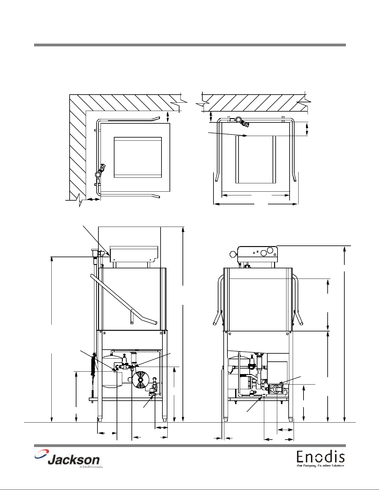
DIMENSIONS FOR TEMPSTAR GPX
A - DRAIN 1 1/2” NPT
B - WATER INLET 1/2” NPT
C - ELECTRICAL CONNECTION
LEGEND
SECTION 1: SPECIFICATION INFORMATION
D - STANDARD WALL CLEARANCE WITH DISHTABLE 4”
E - OUTLET TO BOOSTER HEATER 3/4” NPT
F - INLET FROM BOOSTER HEATER 3/4” NPT
C
D
D
76”
W/ DOOR
OPEN
D
4 7/8”
C
25 1/4”
32”
ALL DIMENSIONS ARE +/- 1/2”
DUE TO ADJUSTABLE FEET.
64 3/8”
17”
MACHINE
OPENING
60 5/8”
ELECTRICAL
CONNECTION
TO THE
FLOOR
E
18 1/4”
5”
F
4 1/4”
13 1/4”
B
21”
A
14"
34”
TABLE
HEIGHT
F
14"
1”
4
11”
Page 10
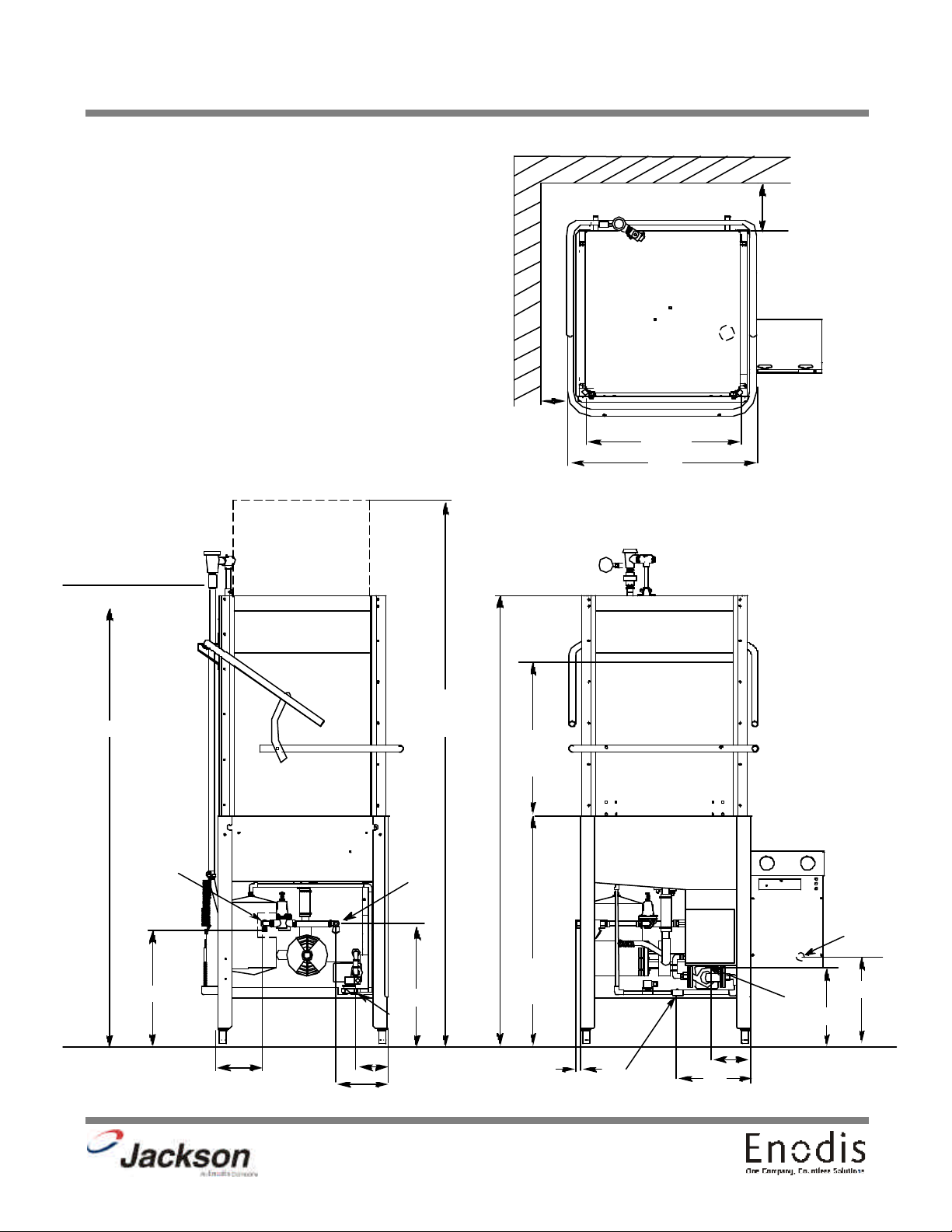
SECTION 1: SPECIFICATION INFORMATION
LEGEND:
DIMENSIONS FOR TEMPSTAR HH GPX
A - DRAIN 1 1/2” NPT
B - WATER INLET 1/2” NPT
C - ELECTRICAL CONNECTION
D - STANDARD WALL CLEARANCE WITH DISHTABLE 4”
E - OUTLET TO BOOSTER HEATER 3/4” N.P.T.
F - INLET FROM BOOSTER HEATER 3/4” N.P.T.
ALL DIMENSIONS ARE +/- 1/2” DUE TO ADJUSTABLE FEET.
D
D
25 1/4”
32”
74 3/4”
E
16 1/4”
5”
7 1/4”
B
19”
F
4 1/4”
86 1/4”
W/ DOOR
OPEN
17”
MACHINE
OPENING
34”
TABLE
HEIGHT
1”
C
12 3/4”
A
12 1/4”
F
11”
3”
5
Page 11

TABLE DIMENSIONS
SECTION 1: SPECIFICATION INFORMATION
2 1/2”
4” MINIMUM
20 1/2”
OPENING
25 1/4”
2 1/2”
20 1/2”
OPENING
4” MINIMUM
25 1/4”
TABLE DIMENSIONS
CORNER INSTALLATION
3/4”
4” MINIMUM
25 1/4”
TABLE DIMENSIONS
STRAIGHT THROUGH INSTALLATION
2 1/2”
20 1/2”
OPENING
20 1/2”
1 1/2” ROLL
TABLE DIMENSIONS
CONNECTION TO DISHMACHINE
25 1/4”
6
Page 12

SECTION 2:
INSTALLATION/OPERATION
INSTRUCTIONS
7
Page 13

SECTION 2: INSTALLATION/OPERATION INSTRUCTIONS
INSTALLATION INSTRUCTIONS
VISUAL INSPECTION: Before installing the unit, check the container and machine for damage. A damaged container is an indi-
cator that there may be some damage to the machine. If there is damage to both the container and machine, do not throw away
the container. The dishmachine has been inspected and packed at the factory and is expected to arrive to you in new, undamaged condition. However, rough handling by carriers or others may result in there being damage to the unit while in transit. If
such a situation occurs, do not return the unit to Jackson; instead, contact the carrier and ask them to send a representative to
the site to inspect the damage to the unit and to complete an inspection report. You must contact the carrier within 48 hours of
receiving the machine. Also, contact the dealer through which you purchased the unit.
UNPACKING THE DISHMACHINE: Once the machine has been removed from the container, ensure that there are no missing parts from the machine. This may not be obvious at first. If it is discovered that an item is missing, contact Jackson immediately to have the missing item shipped to you.
LEVEL THE DISHMACHINE: The dishmachine is designed to operate while being level. This is important to prevent any damage to the machine during operation and to ensure the best results when washing ware. The unit comes with adjustable bullet
feet, which can be turned using a pair of channel locks or by hand if the unit can be raised safely. Ensure that the unit is level
from side to side and from front to back before making any connections.
PLUMBING THE DISHMACHINE: All plumbing connections must comply with all applicable local, state, and national plumbing codes. The plumber is responsible for ensuring that the incoming water line is thoroughly flushed prior to connecting it to
any component of the dishmachine. It is necessary to remove all foreign debris from the water line that may potentially get
trapped in the valves or cause an obstruction. Any valves that are fouled as a result of foreign matter left in the water line, and
any expenses resulting from this fouling, are not the responsibility of the manufacturer.
CONNECTING THE DRAIN LINE: The drain for the Tempstar models covered in this manual are gravity discharge drains. All
piping from the 1-1/2” FNPT connection on the wash tank must be pitched (1/4” per foot) to the floor or sink drain. All piping
from the machine to the drain must be a minimum 1-1/2” NPT and shall not be reduced. There must also be an air gap between
the machine drain line and the floor sink or drain. If a grease trap is required by code, it should have a flow capacity of 5 gallons per minute.
NOTE: This equipment is not recommend for use with deionized water or other aggressive fluids. Use of deionized water or other aggressive fluids will result in corrosion and failure of materials and components. Use of
deionized water or other aggressive fluids will void the manufacturer's warranty.
WATER SUPPLY CONNECTION: Ensure that you have read the section entitled “PLUMBING THE DISHMACHINE” above
before proceeding. Install the water supply line (1/2” pipe size minimum) to the dishmachine line strainer using copper pipe. It
is recommended that a water shut-off valve be installed in the water line between the main supply and the machine to allow
access for service. The water supply line is to be capable of 25 PSI “flow” pressure at the recommended temperature indicated on the data plate.
For the Tempstar GPX, the line should also have the capacity to supply 52.2 GPH @ 25 PSI “flow” pressure.
For the Tempstar HH GPX, the line should also have the capacity to supply 72 GPH @ 25 PSI “flow” pressure.
In areas where the water pressure fluctuates or is greater than the recommended pressure, it is suggested that a water pressure regulator be installed. The Tempstar models covered in this manual come with water pressure regulators as standard
equipment. Please notify Jackson immediately if this component is not present on your machine.
Do not confuse static pressure with flow pressure. Static pressure is the line pressure in a “no flow” condition (all valves and
services are closed). Flow pressure is the pressure in the fill line when the fill valve is opened during the cycle.
It is also recommended that a shock absorber (not supplied with the Tempstar models) be installed in the incoming water line.
This prevents line hammer (hydraulic shock), induced by the solenoid valve as it operates, from causing damage to the equipment.
WATER CONNECTION TO THE GAS BOOSTER HEATER: Refer to page entitled “GAS BOOSTER HEATER CONNECTIONS”.
8
Page 14

SECTION 2: INSTALLATION/OPERATION INSTRUCTIONS
INSTALLATION INSTRUCTIONS
GAS BOOSTER HEATER ELECTRICAL INSTALLATION: The gas booster heater must have a separate electric hookup than
that supplied to the dishmachine. Please refer to the manual supplied with your gas booster heater.
GAS CONNECTION TO THE BOOSTER HEATER: Please refer to the manual supplied with your gas booster heater.
VENTILATION OF THE GAS BOOSTER HEATER: Please refer to the manual supplied with your gas booster heater.
PLUMBING CHECK: Slowly turn on the water supply to the machine after the incoming fill line and the drain line have been
installed. Check for any leaks and repair as required. All leaks must be repaired prior to placing the machine in operation.
ELECTRICAL POWER CONNECTION: Electrical and grounding connections must comply with the applicable portions of the
National Electrical Code ANSI/NFPA 70 (latest edition) and/or other electrical codes.
Disconnect electrical power supply and place a tag at the disconnect switch to indicate that you are working on the circuit.
The dishmachine data plate is located on the right side and to the front of the machine. Refer to the data plate for machine
operating requirements, machine voltage, total amperage load and serial number.
To install the incoming power lines, remove the control box cover. Install 3/4” conduit into the pre-punched holes in the back of
the control box. Route power wires and connect to power block and grounding lug. Install the service wires (L1 and L2) to the
appropriate terminals as they are marked on the terminal block. Install the grounding wire into the lug provided. and tighten the
connections. It is recommended that “DE-OX” or another similar anti-oxidation agent be used on all power connections.
VOLTAGE CHECK: Ensure that the power switch is in the OFF position and apply power to the dishmachine. Check the incoming power at the terminal block and ensure it corresponds to the voltage listed on the data plate. If not, contact a qualified service agency to examine the problem. Do not run the dishmachine if the voltage is too high or too low. Shut off the service breaker and mark it as being for the dishmachine. Advise all proper personnel of any problems and of the location of the service
breaker. Replace the control box cover and tighten down the screws.
9
Page 15

SECTION 2: INSTALLATION/OPERATION INSTRUCTIONS
GAS BOOSTER HEATER CONNECTIONS
WARNING
ENSURE THAT THERE IS NO ELECTRICAL POWER APPLIED TO THE MACHINE WHEN MAKING GAS CONNECTION.
CHECK ALL GAS CONNECTIONS FOR LEAKS PRIOR TO APPLYING POWER.
THE GASES USED FOR COMBUSTION IN THIS DISH MACHINE ARE HIGHLY FLAMMABLE.
DO NOT SMOKE AROUND THIS MACHINE.
ENSURE THAT THE AREA WHERE THIS MACHINE IS TO BE INSTALLED IS WELL-VENTILATED TO PREVENT THE
BUILD-UP OF COMBUSTIBLE GASES.
ENSURE THAT ALL LOCAL HEALTH, FIRE, AND BUILDING CODES ARE BEING ADHERED TO WHEN INSTALLING
THIS MACHINE. VERIFY WITH LOCAL OFFICIALS IF THERE ARE ANY QUESTIONS.
INSTALL A SHUT-OFF VALVE AT THE GAS SOURCE.
Due to the fact that each customer may have different requirements for the orientation of the gas booster heater relative to the
main dishmachine, the hose lengths that connect the two units must be customized during each installation.
To prevent incorrect measurements of the hose, it is recommended to place one barbed hose fitting into the end of the uncut
length of hose coil and attach that fitting to an appropriate connection. Run the hose to the corresponding connection on the
other unit before cutting the hose. Use a barbed hose fitting that is screwed into the second connection on the other unit before
cutting the hose. Use a barbed hose fitting that is screwed onto the second connection to gauge the correct distance. Ensure
a smooth “flow” of hose without any sharp turns or kinks.
To aid in pushing the barbed hose fitting into the hose, place the fitting on a hard surface (i.e. the floor) with the barbed end of
the fitting pointing upward and push the hose down onto the fitting. A small amount of lubricant (i.e. petroleum jelly) may aid in
this process.
Barbed Hose Fitting
Attach the hose fitting to
this connection before
Connection
making the cut at the
other end of the hose.
Hose
10
Cut the hose at the location where
the hose is even with the yellow
plastic stop.
Page 16

SECTION 2: INSTALLATION/OPERATION INSTRUCTIONS
GAS BOOSTER HEATER CONNECTIONS (CONTINUED)
BUILDINGS
WATER
SUPPLY
AN ASTERISK ( )
DENOTES ITEMS
INCLUDED WITH
*
PHOSPHATE
WATER
TREATMENT
CARTRIDGE
*
THE GAS BOOSTER
HEATER
RINSE ARM
DISHMACHINE
PRESSURE
REGULATING
VALVE
Y-STRAINER
3/4" HOSE
GAS BOOSTER
*
TEMPERATURE/PRESSURE
*
GAGE
HEATER
INLET OUTLET
DRAIN VALVE
PRESSURE
*
RELIEF
VALVE
3/4" HOSE
TEMPERATURE/PRESSURE
*
GAGE
ALL COMPONENTS WITHIN THE DOTTED REGION
ARE FOUND WITHIN THE FOOTPRINT OF THE MACHINE.
ALL OTHER ITEMS ARE INSTALLED AT THE SITE.
HEATING COIL
RECIRC
PUMP
VACUUM
BREAKER
PRESSURE
GAGE
RINSE
SOLENOID
VALVE
S
THERMAL
EXPANSION
TANK
11
Page 17

SECTION 2: INSTALLATION/OPERATION INSTRUCTIONS
OPERATION INSTRUCTIONS
PREPARATION: Before proceeding with the start-up of the unit, verify the following:
1. The pan strainer and pump suction strainer are in place and are clean.
2. The overflow tube and o-ring are installed.
3. That the wash and rinse arms are screwed securely into place and that their endcaps are tight. The wash and rinse arms
should rotate freely.
GAS BOOSTER HEATER OPERATION: For all start up and operation information, please refer to the manual supplied with
your gas booster heater.
POWER UP: To energize the unit, turn on the power at the service breaker. The voltage should have been previously verified
as being correct. If not, the voltage will have to be verified.
FILLING THE WASH TUB (TEMPSTAR GPX): Ensure that the delime switch is in the NORMAL position, and place the power
switch into the ON position. The Tempstar model should fill automatically and shut off when the appropriate level is reached
(just below the pan strainer). Verify that the drain stopper is preventing the wash tub water from leaking excessively. There may
be some slight leakage from the drain hole. Verify that there are no other leaks on the unit before proceeding any further. The
wash tub must be completely filled before operating the wash pump to prevent damage to the component. Once the wash tub
is filled, the unit is ready for operation.
FILLING THE WASH TUB (TEMPSTAR HH GPX): For the initial fill, ensure that the cycle selection switch is in the “AUTO”
(automatic) position, and place the power switch in the “ON” position. The unit will fill automatically and run through a rinse
cycle. Open the doors and verify that the water level is correct. Hereafter, the water level is controlled by the overflow tube.
Verify that the drain stopper is preventing the wash tub water from draining excessively. There may be some slight leakage from
the drain hole. Verify that there are no other leaks on the unit before proceeding any further. The wash tub must be completely filled before operating the wash pump to prevent damage to the component. Once the wash tub is filled, the unit is ready for
operation.
WARE PREPARATION: Proper preparation of ware will help ensure good results and less re-washes. If not done properly, ware
may not come out clean and the efficiency of the dishmachine will be reduced. It is important to remember that a dishmachine
is not a garbage disposal and that simply throwing unscraped dishes into the machine simply defeats the purpose altogether
of washing the ware. Scraps should be removed from ware prior to being loaded into a rack. Pre-rinsing and pre-soaking are
good ideas, especially for silverware and casserole dishes. Place cups and glasses upside down in racks so that they do not
hold water during the cycle. The dishmachine is meant not only to clean, but to sanitize as well, to destroy all of the bacteria
that could be harmful to human beings. In order to do this, ware must be properly prepared prior to being placed in the machine.
DAILY MACHINE PREPARATION: Refer to the section entitled “PREPARATION” at the top of this page and follow the instructions there. Afterwards, check that all of the chemical levels are correct and/or that there is plenty of detergent available for the
expected workload.
WARM-UP CYCLES: For a typical daily start-up, it may be necessary to run the machine through 3 cycles to ensure that all of
the cold water is out of the system and to verify that the unit is operating correctly. To cycle the machine, ensure that the power
is on and that the tub has filled to the correct level. Lift the doors and the cycle light will illuminate. When the light goes out,
close the doors, the unit will start, run through the cycle, and shut off automatically. Repeat this two more times. The unit should
now be ready to proceed with the washing of ware.
WASHING A RACK OF WARE: To wash a rack, open the doors completely (being careful for hot water that may drip from the
doors) and slide the rack into the unit. Close the doors and the unit will start automatically. Once the cycle is completed, open
the door (again watching for the dripping hot water) and remove the rack of clean ware. Replace with a rack of soiled ware and
close the doors. The process will then repeat itself.
12
Page 18

SECTION 2: INSTALLATION/OPERATION INSTRUCTIONS
OPERATION INSTRUCTIONS (CONTINUED)
OPERATIONAL INSPECTION: Based upon usage, the pan strainer may become clogged with soil and debris as the workday
progresses. Operators should regularly inspect the pan strainer to ensure it has not become clogged. If the strainer does, it will
reduce the washing capability of the machine. Instruct operators to clean out the pan strainer at regular intervals or as required
by work load.
SHUTDOWN AND CLEANING: At the end of the workday, close the doors. When the unit completes the cycle, turn the power
switch to the OFF position and open the doors. Remove and clean the pan strainer. Remove the drain stopper from the tub and
allow the tub to drain (NOTE: the wash tank water will be hot so caution is advised). Once the wash tub is drained, remove the
pump suction strainer. Remove soil and debris from the strainer and set to the side. Unscrew the wash and rinse arms from
their manifolds. Remove the endcaps and flush the arms with water. Use a brush to clean out the inside of the arms. If the nozzles appear to be clogged, use a toothpick to remove the obstruction. Wipe the inside of the unit out, removing all soil and
scraps. Reassemble the wash and rinse arms and replace them in the unit. The arms only need to be hand tight, do not use
tools to tighten them down. Reinstall the drain stopper
and strainers and close the doors.
WATER CONSUMPTION ISSUES AND EFFICIENCY: The Tempstar HH GPX provides you, the customer, with the ability to
control the hourly rack capacity of the machine. Extending the wash cycle to wash severely soiled ware, such as mixing bowls,
does not increase the machine’s water consumption. However, selecting a longer time cycle does lower the amount of dishes
the machine will be able to wash per hour. It is important for operators to select the correct wash cycle depending on the amount
of washing required. Not every rack of dishes requires the machine to be set on the longest wash cycle!
Using good prescrapping procedures and observing the results of individual racks of ware, operators will soon gain the experience and knowledge required to ensure that the Tempstar HH GPX operates at peak efficiency for your needs.
Water hardness and detergent usage will also effect the results of the Tempstar HH GPX. This manual provides a page entitled “Detergent Control” for your reference. It is recommended that owners and operators take the time to carefully review this
section in order to ensure that everything is done to make sure the Tempstar HH GPX operates at peak performance!
13
Page 19

SECTION 3:
PREVENTATIVE MAINTENANCE
14
Page 20

SECTION 3: PREVENTATIVE MAINTENANCE
PREVENTATIVE MAINTENANCE
The dishmachines covered in this manual are designed to operate with a minimum of interaction with the operator. However,
this does not mean that some items will not wear out in time. Jackson highly recommends that any maintenance and repairs
not specifically discussed in this manual should be performed by QUALIFIED SERVICE PERSONNEL ONLY. Performing maintenance on your dishmachine may void your warranty if it is still in effect, so if you have a question or concern, do not hesitate
to contact one of the QUALIFIED SERVICE AGENCIES listed in the back of this manual.
There are many things that operators can do to prevent catastrophic damage to the dishmachine. One of the major causes of
component failure has to do with prescrapping procedures. A dishmachine is not a garbage disposal; any large pieces of material that are put into the machine shall remain in the machine until they are either broken up (after spreading out on your ware!)
or physically removed. Strainers are installed to help catch debris, but they do no good of they are clogged. Have operators
regularly inspect the pan strainers to ensure (1) that they are free of soil and debris and (2) they are laying flat in the tub.
When cleaning out strainers, do NOT beat them on waste cans. The strainers are made of metal and can be forgiving; but once
severe damage is done, it is next to impossible for the strainer to work in the way it was designed to. Wipe out strainers with
a rag and rinse under a faucet if necessary. For stubborn debris, a toothpick should be able to dislodge any obstructions from
the perforations. Always ensure that strainers are placed back in the machine before operation and that they lay flat in the tub.
You may wish to also refer to the page entitled “Detergent Control” in order to learn more about how your water hardness will
effect the performance of your machine. Hard water makes dishmachines work harder and decreases efficiency.
Again, it is important to remind operators that trying to perform corrective maintenance on the dishmachine could lead to larger problems or even cause harm to the operator. If a problem is discovered; secure the dishmachine using proper shut down
procedures as listed in this manual and contact a QUALIFIED SERVICE AGENCY as listed in the back of this manual.
Some problems, however, may having nothing to do with the machine itself and no amount of preventative maintanence is
going to help. A common problem has to do with temperatures being too low. Verify that the water temperatures coming to your
dishmachine match the requirements listed on the machine data plate. There can be a variety of reasons why your water temperature could be too low and you should discuss it with a QUALIFIED SERVICE AGENCY to determine what can be done.
By following the operating and cleaning instructions in this manual, you should get the most efficient results from your machine.
As a reminder, here are some steps to take to ensure that you are using the dishmachine the way it was designed to work:
1. Ensure that the water temperatures match those listed on the machine data plate.
2. Ensure that all strainers are in place before operating the machine.
3. Ensure that all wash and/or rinse arms are secure in the machine before operating.
4. Ensure that drains are closed/sealed before operating.
5. Remove as much soil from dishes by hand as possible before loading into racks.
6. Do not overfill racks.
7. Ensure that glasses are placed upside down in the rack.
8. Ensure that all chemicals being injected to machine have been verified as being at the correct concentrations.
9. Clean out the machine at the end of every workday as per the instructions in the manual.
10. Always contact a QUALIFIED SERVICE AGENCY whenever a serious problem arises.
11. Follow all safety procedures, whether listed in this manual or put forth by local, state or national codes/regulations.
15
Page 21

SECTION 4:
ELECTRICAL SCHEMATICS
16
Page 22

SECTION 4: ELECTRICAL SCHEMATICS
TEMPSTAR GPX 115 VOLT - 50/60 HERTZ - SINGLE PHASE
17
Page 23

TEMPSTAR GPX 208-230 VOLT - 50/60 HERTZ - SINGLE PHASE
SECTION 4: ELECTRICAL SCHEMATICS
18
Page 24

SECTION 4: ELECTRICAL SCHEMATICS
TEMPSTAR HH GPX 115 VOLT - 50/60 HERTZ - SINGLE PHASE
19
Page 25

TEMPSTAR HH GPX 208-230 VOLT - 50/60 HERTZ - SINGLE PHASE
SECTION 4: ELECTRICAL SCHEMATICS
20
Page 26

SECTION 5:
JACKSON MAINTENANCE &
REPAIR CENTERS
21
Page 27

ALABAMA TO HAWAII
SECTION 5: JACKSON MAINTENANCE & REPAIR CENTERS
ALABAMA:
JONES-McLEOD
APPLIANCE SVC
1616 7TH AVE. NORTH
BIRMINGHAM, AL 35203
(205) 251-0159
800-821-1150
FAX: (205) 322-1440
service@jones-mcleod.com
JONES-McLEOD
APPLIANCE SVC
854 LAKESIDE DRIVE
MOBILE, AL 36693
(334) 666-7278
800-237-9859
FAX: (334) 661-0223
ALASKA:
RESTAURANT
APPLIANCE SVC
7219 ROOSEVELT WAY NE
SEATTLE, WA 98115
(206) 524-8200
800-433-9390
FAX: (206) 525-2890
info@restappl.com
ARIZONA:
AUTHORIZED COMMERCIAL
FOOD EQMT. SVC
4832 SOUTH 35TH STREET
PHOENIX, AZ 85040
(602) 234-2443
800-824-8875
FAX: (602) 232-5862
acsboss@aol.com
GCS SERVICE INC.
PHOENIX, AZ
800-822-2303
ARKANSAS:
BROMLEY PARTS & SVC
10TH AND RINGO
P.O. BOX 1688
LITTLE ROCK, AR 72202
(501) 374-0281
800-482-9269
FAX: (501) 374-8352
service@bromleyparts.com
parts@bromleyparts.com
COMMERCIAL PARTS & SVC.
3717 CHERRY ROAD
MEMPHIS, TN 38118
(901) 366-4587
800-262-9155
FAX: (901) 366-4588
CALIFORNIA:
BARKERS FOOD
MACHINERY SERVICES
5367 SECOND STREET
IRWINDALE, CA 91706
(626) 960-9390
800-258-6999
FAX: (626) 337-4541
service@barkers.com
GCS SERVICE INC.
LOS ANGELES, CA
800-822-2303
P & D APPLIANCE
4220-C ROSEVILLE ROAD
NORTH HIGHLANDS, CA 95660
(916) 974-2772
800-824-7219
FAX:(916) 974-2774
INDUSTRIAL ELECTRIC SVC
5662 ENGINEER DRIVE
HUNTINGON BEACH, CA 92649
(714) 379-7100
800-4573783
FAX: (714) 379-7109
GCS SERVICE INC.
360 LITTLEFIELD AVE
S. SAN FRANCISCO, CA 94080
(650) 635-0720
800-969-4427
FAX: (650) 871-4019
BARKERS FOOD
MACHINERY SERVICES
9373 ACTIVITY ROAD #G
SAN DIEGO, CA 92126
(858) 695-1091
800-995-7955
FAX: (858) 995-7955
GCS SERVICE INC.
9030 KENMAR DR. SUITE 313
SAN DIEGO, CA 92121
(858) 549-8411
800-422-7278
FAX: (858) 549-2323
P & D APPLIANCE SVC
100 SOUTH LINDEN AVE.
S. SAN FRANCISCO, CA 94080
(650) 635-1900
800-424-1414
FAX: (650) 635-1919
pndappl@aol.com
COLORADO:
HAWKINS COMMERCIAL
APPLIANCE SERVICE
3000 S. WYANDOT ST.
ENGLEWOOD, CO 80110
(303) 781-5548
(800) 624-2117
FAX: (303) 761-8861
COLORADO (cont.):
METRO APPLIANCE SERVICE
1640 S BROADWAY
DENVER, CO 80210
(303) 778-1126
800-525-3532
FAX: (303) 778-0268
metroappls@aol.com
CONNECTICUT:
GCS SERVICE INC.
302 MURPHY ROAD
HARTFORD, CT 06114
(860) 549-5575
800-423-1562
FAX: (860) 527-6355
DELAWARE:
AMERICAN KITCHEN MACHINERY & REPAIR
204 QUARRY STREET
PHILADELPHIA, PA 19106
(215) 627-7760
800-848-7760
FAX: (215) 627-1604
GCS SERVICE INC.
817 N. THIRD STREET
PHILADELPHIA, PA
(215)925-6217
800-441-9115
FAX: (215) 925-6208
ELMER SCHULTZ SERVICE
36 BELMONT AVE.
WILLMINGTON, DE 19804
(302) 655-8900
800-225-0599
FAX: (302) 656-3673
elmer2@erols.com
EMR SERVICE DIVISION
106 WILLIAMSPORT CIRCLE
SALISBURY, MD 21804
(410) 543-8197
FAX: (410) 548-4038
FLORIDA:
COMMERCIAL APPLIANCE SVC
8416 LAUREL FAIR CIRCLE
BLDG 6, SUITE 114
TAMPA, FL 33610
(813) 663-0313
800-282-4718
FAX: (813) 663-0212
commercialappliance@worldnet.at
t.net
FLORIDA (cont.):
GCS SERVICE INC
3373 N. W. 168TH STREET
MIAMI, FL 33056
(305) 621-6666
800-766-8966
FAX: (305) 621-6656
GCS SERVICE INC
3902 CORPORES PARK DR.
SUITE 350
TAMPA, FL 33619
(813) 626-6044
800-282-3008
FAX: (813) 621-1174
JONES-McLEOD
APPLIANCE SVC
854 LAKESIDE DRIVE
MOBILE, AL 36693
(334) 666-7278
800-237-9859
FAX: (334) 661-0223
service@jones-mcleod.com
GEORGIA:
GCS SERVICE INC
3127 PRESIDENTIAL DRIVE
ATLANTA, GA 30340
(770) 452-7322
800-334-3599
FAX: (770) 452-7473
SOUTHEASTERN
RESTAURANT SVC.
2200 NORCROSS PKWY.
SUITE 210
NORCROSS, GA 30071
(770) 446-6177
800-235-6516
FAX: (770) 446-3157
info@srs-atl.com
WHALEY FOODSERVICE
REPAIRS
109-A OWENS INDUSTRIAL
DRIVE
SAVANNAH, GA 31405
(912) 447-0827
888-765-0036
FAX: (912) 447-0826
HAWAII:
FOOD EQMT. PARTS & SERVICE CO.
300 PUUHALE RD.
HONOLULU, HI 96819
(808) 847-4871
FAX: (808) 842-1560
fepsco@hula.net
22
Page 28

SECTION 5: JACKSON MAINTENANCE & REPAIR CENTERS
IDAHO TO MISSISSIPPI
IDAHO:
RON'S SERVICE
703 E 44TH STREET STE 10
GARDEN CITY, ID 83714
(208) 375-4073
FAX: (208) 375-4402
RESTAURANT APPLIANCE SVC.
7219 ROOSEVELT WAY NE
SEATTLE, WA 98115
(206) 524-8200
800-433-9390
FAX: (206) 525-2890
info@restappl.com
ILLINOIS:
CONES REPAIR SVC.
2408 40TH AVE.
MOLINE, IL 61265
(309) 797-5323
800-716-7070
FAX: (309)797-3631
jackb@cones.com
EICHENAUER SERVICES INC.
130 S OAKLAND ST.
DECATUR, IL 62522
(217) 429-4229
800-252-5892
FAX: (217) 429-0226
esi@esiquality.com
GCS SERVICE INC.
696 LARCH AVENUE
ELMHURST, IL 60126
(630) 941-7800
800-942-9689
FAX: (630) 941-6048
GCS SERVICE INC.
9722 REAVIS PARK DRIVE
ST. LOUIS, MO 63123
(314) 683-7444
800-284-4427
FAX: (314) 638-0135
INDIANA:
GCS SERVICE INC.
5310 E. 25TH STREET
INDIANAPOLIS, IN 46218
(317) 545-9655
800-727-8710
FAX: (317) 549-6286
IOWA:
GOODWIN-TUCKER GROUP
3509 DELAWARE AVENUE
DES MOINES, IA 50313
(515) 262-9308
800-372-6066
FAX: (515) 262-2936
goodwintuc@aol.com
IOWA (cont.):
CONES REPAIR SVC.
1056 27TH AVENUE SW
CEDAR RAPIDS, IA 52404
(319) 365-3325
800-747-3326
FAX: (319) 365-0885
KANSAS:
GCS SERVICE INC.
6107 CONNECTICUT
KANSAS CITY, MO 64210
(816) 920-5999
800-229-6477
FAX: (816) 920-7387
KENTUCKY:
CERTIFIED SERVICE CENTER
127 DISHMAN LANE
BOWLING GREEN, KY 42101
(270) 783-0012
(877) 907-0012
FAX: (270) 783-0058
CERTIFIED SERVICE CENTER
1051 GOODWIN DRIVE
LEXINGTON, KY 40505
(606) 254-8854
800-432-9269
FAX: (606) 231-7781
jatkins@certifiedsc.com
GCS SERVICE INC.
1002 NANDINO BLVD.
LEXINGTON, KY 40511
(606) 255-0746
800-432-9260
FAX: (606) 255-0748
CERTIFIED SERVICE CENTER
RAMCO BUSINESS PARK
4283 PRODUCE ROAD
LOUISVILLE, KY 40218
(502) 964-7007
800-637-6350
FAX: (502) 964-7202
cwalker@certifiedsc.com
droenigk@certifiedsc.com
GCS SERVICE INC.
4204 SOUTH BROOK STREET
LOUISVILLE, KY 40214
(502) 367-1788
800-752-6160
FAX: (502) 367-0400
LOUISIANA:
BANA PARTS INC.
1501 KUEBLE STREET
HARAHAN, LA 70123
(504) 734-0076
800-325-7543
FAX: (504) 734-8456
LOUISIANA (cont.):
BANA PARTS INC.
4028 GREENWOOD ROAD
SHREVEPORT, LA 71109
(318) 631-6550
800-832-6550
FAX: (318) 636-5675
MAINE:
MRE, INC.
170 JOHN ROBERTS RD UNIT #3
PROTLAND, ME 04106
(207) 772-1152
800-823-9700
FAX: (207) 772-1445
NORTHERN CROWN
SERVICES, INC.
225 INDUSTRIAL WAY
PORTLAND, ME 04103
(207) 797-7333
(800) 696-7560
FAX: (207) 696-1128
steve@northerncrownservices.com
richard@northerncrownservices.com
MARYLAND:
EMR SERVICE DIVISION
700 EAST 25TH STREET
BALTIMORE, MD 21218
(410) 467-8080
800-879-4994
FAX: (410) 467-4191
baltparts@emrco.com
EMR SERVICE DIVISION
106 WILLIAMSPORT CIRCLE
SALISBURY, MD 21804
(410) 543-8197
888-687-8080
FAX: (410) 548-4038
baltparts@emrco.com
EMR SERVICE DIVISION
2626 PITTMAN DRIVE
SILVER SPRING, MD 20910
(301) 588-8080
800-348-2365
FAX: (301) 588-6985
baltparts@emrco.com
GCS SERVICE INC.
2660 PITTMAN DRIVE
SILVER SPRING, MD 20910
(301) 585-7550 (DC)
(410) 792-0338 (BALT)
(800) 638-7278
FAX: (301) 495-4410
MASSACHUSETTS:
ACE SERVICE CO.
95 HAMPTON AVE.
NEEDHAM, MA 02494
(781) 449-4220
800-225-4510 MA & NH
FAX: (781) 444-4789
taceservice@aol.com
MASSACHUSETTS
RESTAURANT SUPPLY
34 SOUTH STREET
SOMERVILLE, MA 02143
(617) 868-1930
800-338-6737
FAX: (617) 868-5331
GCS SERVICE INC.
180 SECOND STREET
CHELSEA, MA 02150
(617) 889-9393
800-225-1155
FAX: (617) 889-1222
GCS SERVICE INC.
302 MURPHY ROAD
HARTFORD, CT 06114
(860) 549-5575
800-723-1562
FAX: (860) 527-6355
MICHIGAN:
GCS SERVICE INC.
31829 WEST EIGHT MILE ROAD
LIVONIA, MI 48152
(248) 426-9500
800-772-2936
FAX: (248) 426-7555
JACKSON SERVICE
COMPANY
3980 BENSTEIN RD.
COMMERCE TOWNSHIP, MI
48382
(248) 363-4159
800-332-4053
FAX: (248) 363-5448
MINNESOTA:
GCS SERVICE INC.
2857 LOUISIANA AVENUE N.
MINNEAPOLIS, MN 55427
(612) 546-4221
800-345-4221
FAX: (612) 546-4286
MISSISSIPPI:
GCS SERVICE INC.
2815 19TH ANENUE, UNIT A
GULFPORT, MS 39501
(228) 864-2722
877-964-2722
FAX: (228) 822-9412
23
Page 29

MISSISSIPPI TO NORTH CAROLINA
SECTION 5: JACKSON MAINTENANCE & REPAIR CENTERS
MISSISSIPPI (cont.):
GCS SERVICE INC.
5755 GALLANT DRIVE.
JACKSON, MS 39206
(601) 956-7800
800-274-5954
FAX: (601) 956-1200
GCS SERVICE INC.
3717 CHERRY ROAD
MEMPHIS, TN 38118
(901) 366-4587
800-262-9155
FAX: (901) 366-4588
MISSOURI:
GCS SERVICE INC.
6107 CONNECTICUT
KANSAS CITY, MO 64120
(816) 920-5999
800-229-6477
FAX: (816) 920-7387
GCS SERVICE INC.
9722 REAVIS PARK DRIVE
ST. LOUIS, MO 63123
(314) 638-7444
800-284-4427
FAX: (314) 638-0135
KAMMERLIN PARTS & SVC.
1359 SOUTH KINGSHIGHWAY
ST. LOUIS, MO 63110
(314) 535-2222
FAX: (314) 535-6205
petek@kps.stl.com
MONTANA:
RESTAURANT
APPLIANCE SVC.
7219 ROOSEVELT WAY NE
SEATTLE, WA 98115
(206) 524-8200
800-433-9390
FAX: (206) 525-2890
info@restappl.com
NEBRASKA:
GOODWIN - TUCKER GROUP
7535 D STREET
OMAHA, NE 68124
(402) 397-2880
800-228-0372
FAX: (402) 397-2881
goodwintuc@aol.com
NEVADA:
HI TECH COMMERCIAL SVC
400 E. MEAD BLVD.
LAS VEGAS, NV 89030
(702) 649-4616
(877) 924-4832
FAX: (702) 649-4607
GCS SERVICE INC.
LAS VEGAS, NV
800-822-2303
NEW HAMPSHIRE:
GCS SERVICE INC.
180 SECOND STREET
CHELSEA, MA 02150
(617)889-9393
800-225-1155
FAX: (617) 889-1222
ACE SERVICE CO.
500 HARVEY RD.
MANCHESTER, NH 03103
(603) 668-5070
800-225-4510
FAX: (603) 626-6067
taceservice@aol.com
MASSACHUSETTS
RESTAURANT SUPPLY
34 SOUTH STREET
SOMERVILLE, MA 02143
(617) 868-1930
800-338-6737
FAX: (617) 868-5331
NEW JERSEY:
JACKSON FASPRAY SVC.
155 SARGEANT AVE.
CLIFTON, NJ 07013
(973) 471-8000
800-356-6740
FAX: (973) 471-1289
jfs155@aol.com
AMERICAN KITCHEN
MACHINERY & REPAIR
204 QUARRY STREET
PHILADELPHIA, PA 19106
(215) 627-7760
800-848-7760
FAX: (215) 627-1604
GCS SERVICE INC.
817 N. THIRD STREET
PHILADELPHIA, PA 19123
(215) 925-6217
800-441-9115
FAX: (215) 925-6208
NEW JERSEY (cont.):
ELMER SCHULTZ SERVICES
201 WASHINGTON AVE.
PLEASANTVILLE, NJ 08232
(609) 641-0317
800-378-1641
FAX:(609) 641-8703
elmer2@erols.com
NEW MEXICO:
STOVE PARTS SUPPLY CO.
2120 SOLANA STREET
FORT WORTH, TX 76117
(817) 831-0381
800-433-1804
FAX: (817) 834-7754
bud@stoveparts.com
HAWKINS COMMERCIAL APPLIANCE SERVICE
300 S. WYANDOT STREET
ENGLEWOOD, CA 80110
(303) 781-5548
800-624-2117
FAX: (303) 761-8861
NEW YORK:
GCS SERVICE INC.
BROOKLYN, NY 11211
800-822-2303
APPLIANCE INSTALLATION
AND SERVICE CORP.
1336 MAIN STREET
BUFFALO, NY 14209
(716) 884-7425
800-722-1252
FAX: (716) 884-0410
ais@worldnet.att.net
B.E.S.T. INC.
3003 GENESEE STREET
BUFFALO, NY 14225
(716) 893-6464
800-338-5011
FAX: (716) 893-6466
bestserv@aol.com
DUFFY'S EQUIPMENT SVC.
3138 ONEIDA STREET
SAUQUOIT, NY 13456
(315) 737-9401
800-443-8339
FAX: (315) 737-7132
duffyequip@aol.com
NORTHERN PARTS & SVC.
21 NORTHERN AVENUE
PLATTSBURGH, NY 12903
(518) 563-3200
800-634-5005
FAX: (800) 782-5424
info@northernparts.com
NEW YORK (cont.):
JACKSON FASPRAY SVC.
155 SARGEANT AVE.
CLIFTON, NJ 07013
(973) 471-8000
800-356-6740
FAX: (973) 471-1289
jfs155@aol.com
ALL ISLAND REPAIR
40-9 BURT DRIVE
DEER PARK, NY 11729
(631) 242-5588
800-323-9411
FAX: (631) 242-6102
A. I. S. COMMERCIAL
PARTS & SVC
1900 COLLEGE AVENUE
ELMIRA HEIGHTS, NY 14901
(607) 734-6072
888-724-7377
FAX: (607) 734-9294
A. I. S. COMMERCIAL
PARTS & SVC
13 WESTR MAIN STREET
FALCONER, NY 14733
(716) 665-6556
800-552-6556
FAX: (716) 665-4227
A. I. S. COMMERCIAL
PARTS & SVC
200 SALINA ST. SUITE 114
LIVERPOOL, NY 13088
(315) 435-0709
800-371-5921
FAX: (315) 453-1412
A. I. S. COMMERCIAL
PARTS & SVC
7387 PITTSFORD VICTOR RD.
ROCHESTER, NY 14610
(716) 461-2370
800-458-4198
FAX: (716) 461-5545
NORTH CAROLINA:
AUTHORIZED APPLIANCE
SERVICE CENTER
1020 TUCKASEEGEE RD.
CHARLOTTE, NC 28208
(704) 377-4501
(800) 532-6127
FAX: (704) 377-4504
WHALEY FOODSERVICE
203-D CREEK RIDGE RD.
GREENSBORO, NC 27604
(336) 333-2333
FAX: (336) 333-2533
24
Page 30

SECTION 5: JACKSON MAINTENANCE & REPAIR CENTERS
NORTH CAROLINA TO TEXAS
NORTH CAROLINA (cont.):
AUTHORIZED APPLIANCE
SERVICE CENTER
109 HINTON AVE.
WILMINGTON, NC 28403
(910) 313-1250
FAX: (910) 313-6130
WHALEY FOODSERVICE
8334-K ARROWRIDGE BLVD
CHARLOTTE, NC 28273
(704) 529-6242
FAX: (704) 529-1558
info@whaleyfoodservice.com
WHALEY FOODSERVICE
REPAIRS
335-105 SHERWEE DRIVE
RALEIGH, NC 27603
(919) 779-2266
FAX: (919) 779-2224
info@whaleyfoodservice.com
WHALEY FOODSERVICE
REPAIRS
6418-101 AMSTERDAM WAY
WILMINGTON, NC 28405
(910) 791-0000
FAX: (910) 791-6662
info@whaleyfoodservice.com
NORTH DAKOTA:
GCS SERVICE INC.
2857 LOUISIANA AVENUE N.
MINNEAPOLIS, MN 55427
(612) 546-4221
800-345-4221
FAX: (612) 546-4286
OHIO:
CERTIFIED SERVICE CENTER
890 REDNA TERRACE
CINCINNATI, OH 45215
(513) 772-6600
800-543-2060
FAX: (513) 612-6600
sbarasch@certifiedsc.com
CERTIFIED SERVICE CENTER
6025 N. DIXIE DRIVE
DAYTON, OH 45414
(937) 898-4040
(800) 257-2611
FAX: (937) 898-4177
dharvey@certifiedsc.com
COMMERCIAL PARTS & SVC.
OF COLUMBUS
1150 WEST MOUND STREET
COLUMBUS, OH 43223
(614) 221-0057
800-837-8327
FAX: (614) 221-3622
OHIO (cont.):
GCS SERVICE INC.
2830 JOHNSTON RD.
COLUMBUS, OH 43219
(614) 476-3225
800-282-5406
FAX: (614) 476-1196
ELECTRICAL APPLIANCE
REPAIR SVC.
5805 VALLEY BELT ROAD
CLEVELAND, OH 44131
(216) 459-8700
800-621-8259
FAX: (216) 459-8707
tomr@electapplrep.com
OKLAHOMA:
HAGAR RESTAURANT EQMT.
1229 W MAIN STREET
OKLAHOMA CITY, OK 73106
(405) 235-2184
800-445-1791
FAX: (405) 236-5592
OREGON:
RON'S SERVICE
16364 SW 72ND AVE
PORTLAND, OR 97224
(503) 624-0890
800-851-4118
FAX: (503) 684-6107
lrobinson@ronsservice.com
PENNSYLVANIA:
A.I.S. COMMERCIAL PARTS &
SERVICE
1816 WEST 26TH STREET
ERIE, PA 16508
(814) 456-3732
800-332-3732
FAX: (814) 452-4843
aiserie@aol.com
ELMER SCHULTZ SVC.
540 NORTH 3RD STREET
PHILADELPHIA, PA 19123
(215) 627-5400
FAX: (215) 627-5408
elmer2@erols.com
K & D PARTS & SERVICE
1833-41 N. CAMERON STREET
HARRISBURG, PA 17103
(717) 236-9039
800-932-0503
FAX: (717) 238-4367
PENNSYLVANIA (cont.):
AMERICAN KITCHEN MACHINERY & REPAIR
204 QUARRY STREET
PHILADELPHIA, PA 19106
(215) 627-7760
800-848-7760
FAX: (215) 627-1604
GCS SERVICE INC.
817 N. THIRD STREET
P.O. BOX 3564
PHILADELPHIA, PA 19123
(215) 925-6217
800-441-9115
FAX: (215) 925-6208
GCS SERVICE INC.
210 VISTA PARK DRIVE
PITTSBURGH, PA 15205
(412) 787-1970
800-738-1221
FAX: (412) 787-5005
RHODE ISLAND:
GCS SERVICE INC.
180 SECOND STREET
CHELSEA, MA 02150
(617)889-9393
800-225-1155
FAX: (617) 889-1222
SOUTH CAROLINA:
AUTHORIZED APPLIANCE
SERVICECENTER
1811 TAYLOR ST.
COLUMBIA, SC 29202
(803) 254-8414
FAX: (803) 254-5146
AUTHORIZED APPLIANCE
SERVICECENTER
2249 AUGUSTA RD.
GREENVILLE, SC 29605
(864) 235-9616
FAX: (864) 235-9623
WHALEY FOODSERVICE
REPAIRS
I 26 & US1
P.O. BOX 4023
WEST COLUMBIA, SC 29170
(803) 791-4420
800-877-2662
FAX: (803) 794-4630
info@whaleyfoodservice.com
WHALEY FOODSERVICE
REPAIRS
748 CONGAREE ROAD
GREENVILLE, SC 29607
(864) 234-7011
800-494-2539
FAX: (864) 234-6662
info@whaleyfoodservice.com
SOUTH CAROLINA (cont.):
WHALEY FOODSERVICE
REPAIRS
1406-C COMMERCE PL.
MYRTLE BEACH, SC 29577
(843) 626-1866
FAX: (843) 626-2632
info@whaleyfoodservice.com
WHALEY FOODSERVICE
REPAIRS
4740-A FRANCHISE STREET
N. CHARLESTON, SC 29418
(843) 760-2110
FAX: (843) 760-2255
info@whaleyfoodservice.com
SOUTH DAKOTA:
GCS SERVICE INC.
2857 LOUISIANA AVENUE N.
MINNEAPOLIS, MN 55247
(612) 546-4221
800-345-4221
FAX: (612) 546-4286
TENNESSEE:
GCS SERVICE INC.
3717 CHERRY ROAD
MEMPHIS, TN 38118
(901) 366-4587
800-262-9155
FAX: (901) 366-4588
GCS SERVICE INC.
748 FESSLERS LANE
NASHVILLE, TN 37210
(615) 244-8050
800-831-7174
FAX: (615) 244-8885
TEXAS:
GCS SERVICE INC.
AUSTIN, TX
800-822-2303
ARMSTRONG
REPAIR CENTER
1700 S LAMAR BLVD #327
AUSTIN, TX 78704
(512) 416-1101
800-392-5322
FAX: (512) 416-6912
ARMSTRONG
REPAIR CENTER
5110 GLENMONT DRIVE
HOUSTON, TX 77081
(713) 666-7100
800-392-5325
FAX: (713) 661-0520
gm@armstrongrepair.com
25
Page 31

TEXAS TO WYOMING/CANADA
SECTION 5: JACKSON MAINTENANCE & REPAIR CENTERS
TEXAS (cont.):
COMMERCIAL KITCHEN
REPAIR CO.
1377 N BRASOS
P.O BOX 831128
SAN ANTONIO, TX 78207
(210) 735-2811
800-292-2120
FAX: (210) 735-7421
brock@commercialkitchen.com
GCS SERVICE INC.
440 WRANGLER DRIVE #100
COPPELL, TX 75019
(972) 906-0307
800-442-5026
FAX: (972) 906-9886
GCS SERVICE INC.
HOUSTON, TX
800-822-2303
GCS/STOVE PARTS
2120 SOLANA STREET
FORT WORTH, TX 76117
(817) 831-0381
800-433-1804
FAX: (817) 834-7754
bud@stoveparts.com
UTAH:
LA MONICA'S RESTAURANT
EQMT. SVC.
6182 SOUTH STRATLER
AVENUE
MURRAY, UT 84107
(801) 263-3221
800-527-2561
FAX: (801) 263-3229
lamonica81@aol.com
GCS SERVICE INC.
1366 S. 400 WEST
SALT LAKE CITY, UT 84115
(801) 487-3653
800-955-9201
FAX: (801) 487-2253
VERMONT:
NORTHERN PARTS & SVC.
4874 S. CATHERINE STREET
PLATTSBURGH, NY 12901
(518) 563-3200
800-634-5005
FAX: (800) 782-5424
info@northernparts.com
GCS SERVICE INC.
180 SECOND STREET
CHELSEA, MA 02150
(617)889-9393
800-225-1155
FAX: (617) 889-1222
VIRGINIA:
DAUBERS, INC.
7645 DYNATECH COURT
SPINGFIELD, VA 22153
(703) 866-3600
800-554-7788
FAX: (703) 866-4071
daubers@aol.com
GCS SERVICE INC.
2660 PITTMAN DRIVE
SILVER SPRING, MD 20910
(301) 585-7550(DC)
(410) 792-0388(BALT)
800-638-7278
FAX: (301)495-4410
GCS SERVICE INC.
RICHMOND, VA
800-822-2303
WASHINGTON:
RESTAURANT APPLIANCE SVC
7219 ROOSEVELT WAY, NE
SEATTLE, WA 98115
(206) 524-8200
800-433-9390
FAX: (206) 525-2890
info@restappl.com
WEST VIRGINIA:
STATEWIDE SERVICE, INC.
603 MAIN AVE.
NITRO, WV 25143
(304) 755-1811
(800) 441-9739
FAX: (304) 755-4001
sws3182@aol.com
WISCONSIN:
APPLIANCE SERVICE
CENTER, INC.
2439 ATWOOD AVE
MADISON, WI 53704
(608) 246-3160
800-236-7440
FAX: (608) 246-2721
ascmad@execpc.com
APPLIANCE SERVICE
CENTER, INC.
6843 W. BELLOIT RD.
WEST ALLIS, WI 53219
(414) 543-6460
800-236-6460
FAX: (414) 543-6480
ascmil@execpc.com
WISCONSIN (cont.):
APPLIANCE SERVICE CENTER
786 MORRIS AVE
GREEN BAY, WI 54304
(920) 496-9993
800-236-0871
FAX: (920) 496-9927
ascfox@execpc.com
METROPOLITAN SERVICE
3210 LONDON RD.
EAU CLAIRE, WI 54701
(715) 832-0555
800-848-3945
FAX: (715) 832-7813
WYOMING:
HAWKINS COMMERCIAL
APPLIANCE SERVICE
300 S. WYANDOT ST.
ENGLEWOOD, CO 80110
(303) 781-5548
(800) 624-2117
FAX: (303) 761-5561
johns@hawkinscommercial.com
METRO APPLIANCE SERVICE
1640 S BROADWAY
DENVER, CO 80210
(303) 778-1126
800-525-3532
FAX: (303) 778-0268
metroappls@aol.com
CANADA
Garland Commercial
Ranges, Ltd.
1177 KAMATO ROAD
MISSISSAUGA, ONTARIO L4W
1X4
(905) 624-0260
800-427-6668
FAX: (905) 624-0623
26
 Loading...