

Page 1

TEMPSTAR
(380 VOLT, 50 HZ, 3 PHASE MODEL)
HOT WATER SANITIZING UPRIGHT
DOOR DISHMACHINES
SERVICESERVICE
MANUALMANUAL
Visit Jackson on the Internet at:
www.jacksonmsc.com
July 26, 2000 P/N 7610-002-23-91
Page 2

MANUFACTURERS WARRANTY
ONE YEAR LIMITED PARTS & LABOR WARRANTY
ALL NEW JACKSON DISHWASHERS ARE WARRANTED TO THE ORIGINAL PURCHASER TO BE FREE FROM
DEFECTS IN MATERIAL OR WORKMANSHIP, UNDER NORMAL USE AND OPERATION FOR A PERIOD OF (1) ONE
YEAR FROM THE DATE OF PURCHASE, BUT IN NO EVENT TO EXCEED (18) EIGHTEEN MONTHS FROM THE DATE
OF SHIPMENT FROM THE FACTORY.
Jackson MSC agrees under this warranty to repair or replace , at its discretion, any original part which fails under normal use due to faulty
material or workmanship during the warranty period, providing the equipment has been unaltered, and has been properly installed, maintained and operated in accordance with the applicable factory instruction manual furnished with the machine and the failure is reported to
the authorized service agency within the warranty period. This includes the use of factory specified genuine replacement parts, purchased
directly from a Jackson authorized parts distributor or service agency. Use of generic replacement parts may create a hazard and void warranty certification.
The labor to repair or replace such failed part will be paid by Jackson MSC, within the continental United States, Hawaii and Canada, dur ing the warranty period provided a Jackson MSC authorized service agency, or those having prior authorization from the factory, performs
the service. Any repair work by persons other than a Jackson MSC authorized service agency is the sole responsibility of the customer.
Labor coverage is limited to regular hourly rates, overtime premiums and emergency service charges will not be paid by Jackson MSC.
Accessory components not installed by the factory carry a (1) one year parts warranty only. Accessory components such as table limit
switches, pressure regulators, pre rinse units, etc. that are shipped with the unit and installed at the site are included. Labor to repair or
replace these components is not covered by Jackson MSC.
This warranty is void if failure is a direct result from shipping, handling, fire, water, accident, misuse, acts of god, attempted repair by unauthorized persons, improper installation, if serial number has been removed or altered, or if unit is used for purpose other than it was originally intended.
TRAVEL LIMITATIONS
Jackson MSC limits warranty travel time to (2) two hours and mileage to (100) one hundred miles. Jackson MSC will not pay for travel time
and mileage that exceeds this, or any fees such as those for air or boat travel without prior authorization.
WARRANTY REGISTRATION CARD
The warranty registration card supplied with the machine must be returned to Jackson MSC within 30 days to validate the warranty.
REPLACEMENT PARTS WARRANTY
Jackson replacement parts are warranted for a period of 90 days from the date of installation or 180 days from the date of shipment from
the factory, which ever occurs first.
PRODUCT CHANGES AND UPDATES
Jackson MSC reserves the right to make changes in design and specification of any equipment as engineering or necessity requires.
THIS IS THE ENTIRE AND ONLY WARRANTY OF JACKSON MSC. JACKSON’S LIABILITY ON ANY CLAIM OF ANY KIND, INCLUDING
NEGLIGENCE, WITH RESPECT TO THE GOODS OR SERVICES COVERED HEREUNDER, SHALL IN NO CASE EXCEED THE PRICE
OF THE GOODS OR SERVICES OR PART THEREOF WHICH GIVES RISE TO THE CLAIM.
THERE ARE NO WARRANTIES, EXPRESSED OR IMPLIED, INCLUDING FOR FITNESS OR MERCHANTABILITY, THAT ARE NOT SET
FORTH HEREIN, OR THAT EXTEND BEYOND THE DURATION HEREOF. UNDER NO CIRCUMSTANCES WILL JACKSON MSC BE
LIABLE FOR ANY LOSS OR DAMAGE, DIRECT OR CONSEQUENTIAL, OR FOR THE DAMAGES IN THE NATURE OF PENALTIES,
ARISING OUT OF THE USE OR INABILITY TO USE ANY OF ITS PRODUCTS.
ITEMS NOT COVERED
This warranty does not cover adjustments to timer cams or thermostats, cleaning wash arms or strainers, or replacement of wear items such
as curtains, squeeze tubes, drain balls, door guides, or gaskets beyond 30 days from installation of unit. Also not covered are conditions
caused by the use of incorrect (non commercial) grade detergents, excessive supply water temperature or pressure, or hard water conditions.
Page 3

TABLE OF CONTENTS
Section Title Page
I GENERAL SECTION
Specifications of the Tempstar 1
Detail of the Tempstar Data Plate 2
General Notes 3
II INSTALLATION INSTRUCTIONS 4
III DETERGENT CONTROL 5
IV INSTALLATION CHECKLIST 6
V OPERATION INSTRUCTIONS 7
VI TROUBLESHOOTING SECTION 8
VII DRAWINGS AND PARTS SECTION
Dimensions 12
Table Dimensions 13
Control Box Assembly 14
Incoming Plumbing Assembly 16
Outlet Plumbing Assembly 19
Booster Tank Assembly 20
Thermostats 21
Hood Assembly 22
Tub Front Assembly 23
Inner Tub Assembly 25
Wash Heaters/Rinse Heaters 26
Cantilver Arm/Door Assemblies 27
Wash & Rinse Arms/Manifolds 29
Wash Pump Exploded View 31
Wash Motor Hanger/Track Assemblies 33
Ordering Replacement Wire 34
Conduit and Fittings 35
Ordering Replacement Fasteners 36
Schematic, 380 Volt, 50 Hz 38
VIII IMPORTANT INFORMATION DATA SHEET 39
i
Page 4

SPECIFICATIONS ofthe TEMPSTAR
PERFORMANCE/CAPABILITIES
OPERATING CAPACITY (RACKS/HOUR)
RACKS PER HOUR 57
DISHES PER HOUR 1425
GLASSES PER HOUR 1425
OPERATING CYCLE (SECONDS)
WASH TIME 45
RINSE TIME 11
DWELL TIME 2
TOTAL CYCLE TIME 60
TANK CAPACITY (GALLONS)
WASH TANK (MINIMUM) 8.0
BOOSTER TANK 3.0
TANK CAPACITY (LITERS)
WASH TANK (MINIMUM) 30.3
BOOSTER TANK 11.4
ELECTRICAL REQUIREMENTS
WASH PUMP MOTOR HP 3/4
AMPERAGE LOADS (12 KW BOOSTER HEATER)
VOLTS PHASE AMPS
380 3 43.6
AMPERAGE LOADS (14 KW BOOSTER HEATER)
VOLTS PHASE AMPS
380 3 48.4
WATER REQUIREMENTS
INLET TEMPERATURE (12 KW) 140
INLET TEMPERATURE (14 KW) 110
INLET TEMPERATURE (12 KW) 60
INLET TEMPERATURE (14 KW) 43.3
GALLONS PER HOUR 52.0
LITERS PER HOUR 196.8
WATER LINE SIZE I.P.S. (Minimum) 3/4”
DRAIN LINE SIZE I.P.S. (Minimum) 1-1/2”
°F
°F
°C
°C
WASH PUMP CAPACITY
GALLONS PER MINUTE 150
LITERS PER MINUTE 567.8
TEMPERATURES
WASH--RINSE ---°F (MINIMUM) 180
WASH--RINSE ---°C (MINIMUM) 82.2
°F (MINIMUM) 150
°C (MINIMUM) 65.6
FLOW PRESSURE P.S.I. (Optimum) 20
FLOW PRESSURE (KG/SQ. CM) (Optimum) 1.41
FRAME DIMENSIONS
WIDTH 25 3/4”
65.4 CM
DEPTH 25 1/4”
64.1 CM
HEIGHT 56 3/4”
144.1 CM
STANDARD TABLE HEIGHT 34”
86.4 CM
MAXIMUM INSIDE CLEARANCE 17 1/4”
43.8 CM
1
Page 5
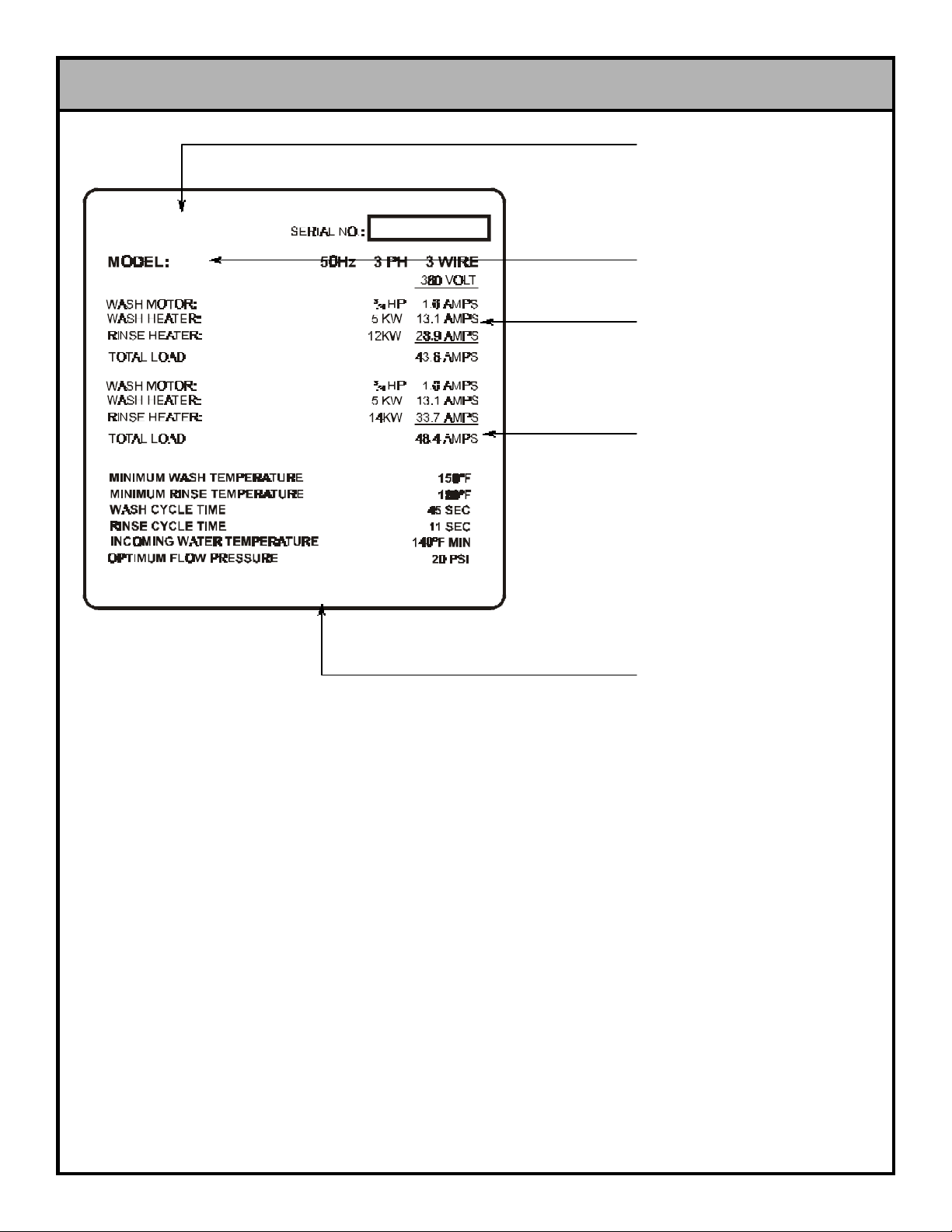
DETAIL of the TEMPSTAR DATA PLATE
MANUFACTURER’S
LOGO
MODEL DESIGNATION
(I.E. “TEMPSTAR”)
AMPERAGE LOAD
INFORMATION
MINIMUM PARAMETERS
(SEE NOTE 1)
MANUFACTURERS
ADDRESS INFORMATION
The data plate is located (standing before the unit) on the right side front corner, directly under the tub lip. Under no circumstances
should the data plate be removed from the unit. The data plate is essential in identifying the particular characteristics of your machine
and is of great benefit to installers, operators, and maintenance personnel. It is recommended that, in the event the data plate is
removed, you copy down the essential information on the final page in this manual for reference before installation. Do not use the
above data plate to represent your dishmachine. The data plate above is a generic representation used only to show you where to
locate information.
2
Page 6

GENERAL NOTES SECTION
Before connecting, operating, or adjusting any of the dishmachines covered in this manual, please carefully read through the entire
manual to familiarize yourself with the machine and its proper operation. This manual contains important operating, safety, and maintenance information concerning your dishmachine. You must follow the instructions and guidelines provided in this manual to ensure
that your warranty remains in effect.
FOR SERVICE PERSONNEL: Jackson MSC Inc. provides technical support for all of the dishmachines detailed in this manual. We
strongly recommend that you refer to this manual before making a call to our technical support staff. Please have this manual with you
when you call so that our staff can refer you, if necessary, to the proper page. Technical support is avaliable from 8:00 a.m. to 5:00 p.m.
(EST), Monday through Friday. Technical support is not available on holidays. Contact technical support toll-free at 1-888-800-5672.
Please remember that technical support is available for service personnel only. Non-service personnel should refer to the list of provided service agencies in this manual for local service support.
NOTES CONCERNING THE TEMPSTAR MODEL DATA PLATES:
NOTE 1: This area of the data plate denotes the minimum parameters that must be met in order for your dishmachine to operate at the
designed level of efficiency. Not meeting the required parameters can result in substandard performance of the dishmachine. Do not
refer to the data plate example in this manual for the parameters of your machine; instead, refer to the data plate affixed to the machine.
Not every Tempstar model machine operates the same way. If you are unsure of whether or not you are meeting the required minimum
parameters, contact your nearest Jackson authorized service agency.
3
Page 7

INSTALLATION INSTRUCTIONS
VISUAL INSPECTION: Before installing the unit, check the container and machine for damage. A damaged container is an indicator that there may be some damage to the machine. If there is
damage to both the container and machine, do not throw away the
container. The dishmachine has been inspected and packed at
the factory and is expected to arrive to you in new, undamaged
condition. However, rough handling by carriers or others may
result in there being damage to the unit while in transit. If such a
situation occurs, do not return the unit to Jackson; instead, contact
the carrier and ask them to send a representative to the site to
inspect the damage to the unit and to complete an inspection
report.. You must contact the carrier within 48 hours of receiving
the machine. Also, contact the dealer through which you purchased the unit.
UNPACKING THE DISHMACHINE: Once the machine has been
removed from the container, ensure that there are no missing
parts from the machine. This may not be obvious at first. If it is discovered that an item is missing, contact Jackson immediately to
have the missing item shipped to you.
In areas where the water pressure fluctuates or is greater than the
recommended pressure, it is suggested that a water pressure regulator be installed. The Tempstar models covered in this manual
come with water pressure regulators as standard equipment.
Please notify Jackson immediately if this component is not present on your machine.
Do not confuse static pressure with flow pressure. Static pressure
is the line pressure in a “no flow” condition (all valves and services
are closed). Flow pressure is the pressure in the fill line when the
fill valve is opened during the cycle.
It is also recommended that a shock absorber (not supplied with
the Tempstar model) be installed in the incoming water line. This
prevents line hammer (hydraulic shock), induced by the solenoid
valve as it operates, from causing damage to the equipment.
PLUMBING CHECK: Slowly turn on the water supply to the
machine after the incoming fill line and the drain line have been
installed. Check for any leaks and repair as required. All leaks
must be repaired prior to placing the machine in operation.
LEVEL THE DISHMACHINE: The dishmachine is designed to
operate while being level. This is important to prevent any damage to the machine during operation and to ensure the best
results when washing ware. The unit comes with adjustable bullet
feet, which can be turned using a pair of channel locks or by hand
if the unit can be raised safely. Ensure that the unit is level from
side to side and from front to back before making any connections.
PLUMBING THE DISHMACHINE: All plumbing connections must
comply with all applicable local, state, and national plumbing
codes. The plumber is responsible for ensuring that the incoming
water line is throroughly flushed prior to connecting it to any component of the dishmachine. It is necessary to remove all foreign
debris from the water line that may potentially get trapped in the
valves or cause an obstruction. Any valves that are fouled as a
result of foreign matter left in the water line, and any expenses
resulting from this fouling, are not the responsibility of the manufacturer.
CONNECTING THE DRAIN LINE: The drain for the Tempstar
models covered in this manual are gravity disharge drains. All piping from the 1-1/2” MNPT connection on the waste accumulator
must be pitched (1/4” per foot) to the floor or sink drain. All piping
from the machine to the drain must be a minimum 1-1/2” I.P.S. and
shall not be reduced. There must also be an air gap between the
machine drain line and the floor sink or drain. If a grease trap is
required by code, it should have a flow capacity of 5 gallons per
minute.
WATER SUPPLY CONNECTION: Ensure that you have read the
section entitled “PLUMBING THE DISHMACHINE” above before
proceding. Install the water supply line (3/4” pipe size minimum) to
the dishmachine line strainer using copper pipe. It is recommended that a water shut-off valve be installed in the water line between
the main supply and the machine to allow access for service. The
water supply line is to be capable of 25 PSI “flow” pressure at the
recommended temperature indicated on the data plate.
ELECTRICAL POWER CONNECTION: Electrical and grounding
connections must comply with the applicable portions of the
National Electrical Code ANSI/NFPA 70 (latest edition) and/or
other electrical codes.
Disconnect electrical power supply and place a tag at the disconnect switch to indicate that you are working on the circuit.
The dishmachine data plate is located on the right side and to the
front of the machine. Refer to the data plate for machine operat ing requirements, machine voltage, total amperage load and serial number.
To install the incoming power lines, open the control box. This will
require taking a phillipshead screwdriver and removing the four (4)
screws on the front cover of the control box. Install 3/4” conduit
into the pre-punched holes in the back of the control box. Route
power wires and connect to power block and grounding lug. Install
the service wires (L1, L2, and L3 (3 phase only)) to the appropriate terminals as they are marked on the terminal block. Install the
grounding wire into the lug provided. Tighten the connections and
perform the “pull test”. The tightened wires should remain in place
after giving the wires a moderate pull to see if they will come
loose.
It is recommended that “DE-OX” or another similar anti-oxidation
agent be used on all power connections.
VOLTAGE CHECK: Ensure that the power switch is in the OFF
position and apply power to the dishmachine. Check the incoming
power at the terminal block and ensure it corresponds to the volt age listed on the data plate. If not, contact a qualified service
agency to examine the problem. Do not run the dishmachine if the
voltage is too high or too low. Shut off the service breaker and
mark it as being for the dishmachine. Advise all proper personnel
of any problems and of the location of the service breaker.
Replace the control box cover and tighten down the screws.
4
Page 8

DETERGENT CONTROL
Detergent usage and water hardness are two factors that contribute greatly to how efficiently your dishmachine will operate. Using
detergent in the proper amount can become, in time, a source of substantial savings. A qualified water treatment specialist can tell you
what is needed for maximum efficiency from your detergent, but you should still know some basics so you’ll understand what they are
talking about.
First, you must understand that hard water greatly effects the performance of the dishmachine. Water hardness is the amount of dissolved calcium and magnesium in the water supply. The more dissolved solids in the water, the greater the water hardness. Hard water
works against detergent, thereby causing the amount of detergent required for washing to increase. As you use more detergent, your
costs for operating the dishmachine will increase and the results will decrease. The solids in hard water also may build-up as a scale
on wash and rinse heaters, decreasing their ability to heat water. Water temperature is important in removing soil and sanitizing dishes. If the water cannot get hot enough, your results may not be satisfactory. This is why Jackson recommends that if you have installed
the machine in an area with hard water, that you also install some type of water treatment equipment to help remove the dissolved
solids from the water before it gets to the dishmachine.
Second, hard water may have you adding drying agents to your operating cycle to prevent spotting, when the real problem is deposit ed solids on your ware. As the water evaporates off of the ware, the solids will be left behind to form the spotting and no amount of drying agent will prevent this. Again, using treated water will undoubtedly reduce the occurences of this problem.
Third, treated water may not be suitable for use in other areas of your operation. For instance, coffee made with soft water may have
an acid or bitter flavor. It may only be feasible to install a small treatment unit for the water going into the dishmachine itself. Discuss
this option with your qualified water treatment specialist.
Even after the water hardness problems have been solved, there still must be proper training of dishmachine operators in how much
detergent is to be used per cycle. Talk with your water treatment specialist and detergent vendor and come up with a complete training program for operators. Using too much detergent has as detrimental effects as using too little. The proper amount of detergent must
be used for job. It is important to remember that certain menu items may require extra detergent by their nature and personnel need to
be made aware of this. Experience in using the dishmachine under a variety of conditions, along with good training in the operation of
the machine, can go a long way in ensuring your dishmachine operates as efficiently as possible.
Certain dishmachine models require that chemicals be provided for proper operation and sanitization. Some models even require the
installation of third-party chemical feeders to introduce those chemicals to the machine. Jackson does not recommend or endorse any
brand name of chemicals or chemical dispensing equipment. Contact your local chemical distributor for questions concerning these
subjects.
Some dishmachines come equipped with integral solid detergent dispensers. These dispensers are designed to accomodate detergents in a certain sized container. If you have such a unit, remember to explain this to your chemical distributor upon first contacting
them.
As explained before, water temperature is an important factor in ensuring that your dishmachine functions properly. The data plate located on each unit details what the minimum temperatures must be for either the incoming water supply, the wash tank and the rinse tank,
depending on what model of dishmachine you have installed. These temperatures may also be followed by temperatures that Jackson
recommends to ensure the highest performance from you dishmachine. However, if the minimum requirements are not met, the
chances are your dishes will not be clean or sanitized. Remember, a dish can look clean, but it may not be sanitized. Instruct your dishmachine operators to observe the required temperatures and to report when they fall below the minimum allowed. A loss of temperature can indicate a much larger problem such as a failed heater or it could also indicate that the hot water heater for your operation is
not up to capacity and a larger one may need to be installed.
There are several factors to consider when installing your dishmachine to ensure that you get the best possible results from it and that
it operates at peak efficiency for many years. Discuss your concerns with your local chemical distibutor and water treatment specialist
before there is a problem.
5
Page 9

INSTALLATION CHECKLIST
CHECK OFF THE FOLLOWING ITEMS AS THEY ARE COMPLETED BEFORE PROCEEDING TO OPERATION OF DISHMACHINE.
Has the dishmachine been checked for concealed/hidden damage?
Has the dishmachine and the surrounding area been properly vented in accordance with all applicable codes?
Has the dishmachine been properly leveled?
Has the drain plumbing been installed with an air gap?
Has the service voltage been checked to ensure that it meets the electrical requirements listed on the dishma-
chine’s data plate?
Has the dishmachine been properly grounded?
Has the dishmachine circuit breaker/service breaker been sized correctly, given the dishmachine’s load, and has it
been marked clearly and identified to all pertinent personnel?
Has the incoming water supply been flushed for debris?
Is the hot water supply at the minimum temperature as indicated on the dishmachine data plate?
Is the incoming water supply at 20 PSI?
Is the incoming water supply line at 3/4” minimum?
6
Page 10

OPERATION INSTRUCTIONS
PREPERATION: Before proceeding with the start-up of the unit,
verify the following:
1. The pan strainer and pump suction strainer are in
place and are clean.
2. The overflow tube and o-ring are installed.
3. That the wash and rinse arms are screwed securely
into place and that their endcaps are tight. The wash
and rinse arms should rotate freely.
unit will start automatically. Once the cycle is completed, open the
door (again watching for the dripping hot water) and remove the
rack of clean ware. Replace with a rack of soiled ware and close
the doors. The process will then repeat itself.
OPERATIONAL INSPECTION: Based upon usage, the pan
strainer may become clogged with soil and debris as the workday
progresses. Operators should reguarly inspect the pan strainer to
ensure it has not become clogged. If the strainer does, it will
reduce the washing capability of the machine. Instruct operators
to clean out the pan strainer at regular intervals or as required by
work load.
POWER UP: To energize the unit, turn on the power at the service
breaker. The voltage should have been previously verified as
being correct. If not, the voltage will have to be verified.
FILLING THE WASH TUB: Ensure that the delime switch is in the
NORMAL position, and place the power switch into the ON position. The Tempstar should fill automatically and shut off when the
appropriate level is reached (just below the pan strainer). Verify
that the drain stopper is preventing the wash tub water from leaking excessively. There may be some slight leakage from the drain
hole. Verify that there are no other leaks on the unit before proceeding any further. The wash tub must be completely filled before
operating the wash pump to prevent damage to the component.
Once the wash tub is filled, the unit is ready for operation.
WARE PREPERATION: Proper preparation of ware will help
ensure good results and less re-washes. If not done properly,
ware may not come out clean and the efficiency of the dishmchine
will be reduced. It is important to remember that a dishmachine is
not a garbage disposal and that simply throwing unscrapped dishes into the machine simply defeats the purpose altogether of
washing the ware. Scraps should be removed from ware prior to
being loaded into a rack. Pre-rinsing and pre-soaking are good
ideas, especially for silverware and casserole dishes. Place cups
and glasses upside down in racks so that they do not hold water
during the cycle. The dishmachine is meant not only to clean, but
to sanitize as well, to destroy all of the bacteria that could be
harmful to human beings. In order to do this, ware must be properly prepared prior to being placed in the machine.
SHUTDOWN AND CLEANING: At the end of the workday, close
the doors. When the unit completes the cycle, turn the power
switch to the OFF position and open the doors. Remove and clean
the pan strainer. Remove the drain stopper from the tub and allow
the tub to drain (NOTE: the wash tank water will be hot so caution
is advised). Once the wash tub is drained, remove the pump suction strainer. Remove soil and debris from the strainer and set to
the side. Unscrew the wash and rinse arms from their manifolds.
Remove the endcaps and flush the arms with water. Use a brush
to clean out the inside of the arms. If the nozzles appear to be
clogged, use a toothpick to remove the obstruction. Wipe the
inside of the unit out, removing all soil and scraps. Reassembly
the wash and rinse arms and replace them in the unit. The arms
only need to be hand tight, do not use tools to tighten them down.
Reinstall the drain stopper and strainers and close the doors.
DAILY MACHINE PREPERATION: Refer to the section entitled
“PREPARATION” at the top of this page and follow the instructions
there. Afterwards, check that all of the chemical levels are correct
and/or that there is plenty of detergent available for the expected
workload.
WARM-UP CYCLES: For a typical daily start-up, it may be necessary to run the machine through 3 cycles to ensure that all of the
cold water is out of the system and to verify that the unit is operating correctly. To cycle the machine, ensure that the power is on
and that the tub has filled to the correct level. Lift the doors and
the cycle light will illuminate. When the light goes out, close the
doors, the unit will start, run through the cycle, and shut off auto matically. Repeat this two more times. The unit should now be
ready to proceed with the washing of ware.
WASHING A RACK OF WARE: To wash a rack, open the doors
completely (being careful for hot water that may drip from the
doors) and slide the rack into the unit. Close the doors and the
7
Page 11

TROUBLESHOOTING SECTION
Dishmachine will not fill after the door
Dishmachine will not fill after the door
WARNING: Inspection, testing and repair of electrical equipment should only be performed by a qualified service techni cian. Many of the tests require that the unit have power to it and live electrical components be exposed. USE EXTREME
CAUTION WHEN TESTING THE MACHINE.
Symptom
is closed. Power "ON" light is
illuminated.
is closed. Power "ON" light is not
illuminated.
Possible Cause Action
Faulty rinse solenoid valve. Repair or replace valve as required.
Faulty door switch. Verify the wiring of the switch; if
correct, replace the switch.
Fouled/faulty high level probe. Clean probe if fouled. If clean and
still not working, replace.
Service breaker tripped. Reset. If the breaker trips again,
contact an electrician to verify the
amp draw of the machine.
Machine not connected to power
source.
Verify that the machine has been
properly connected to the power
source.
Dishmachine will not run after the
door is closed. Power "ON" light is
illuminated and unit is filling.
Faulty power switch. Verify the wiring of the switch; if
correct, replace the switch.
Timer motor faulty. Verify that the timer is rotating. If
not, check to see that the motor is
receiving power. If so, replace the
motor and/or timer assembly.
Wash motor faulty/damaged. Verify that the wash motor is getting
power. If so, replace the motor.
Wash motor contactor faulty. Check for continuity; if contacts are
open, replace the contactor.
8
Page 12

TROUBLESHOOTING SECTION
WARNING: Inspection, testing and repair of electrical equipment should only be performed by a qualified service techni cian. Many of the tests require that the unit have power to it and live electrical components be exposed. USE EXTREME
CAUTION WHEN TESTING THE MACHINE.
Symptom
Dishmachine runs continuously in
the wash cycle.
Wash or rinse heater does not work.
Possible Cause Action
Machine is in Delime mode. Flip NORMAL/DELIME switch to
NORMAL mode.
Timer motor faulty. Verify that the timer is rotating. If
not, check to see that the motor is
receiving power. If so, replace the
motor and/or timer assembly.
Cam timer jammed by obstruction. Remove obstruction.
Faulty heater element. Check element for continuity; if
open, replace the heater.
Faulty heater contactor. Replace the contactor.
Dishmachine fills slowly and/or the
rinse is week.
Misadjusted/faulty thermostat(s). Verify operation and setting of
thermostats, replace if necessary.
Clogged or obstructed rinse arms. Remove and clean rinse arms.
Low incoming water pressure. Adjust the water pressure regulator
to ensure that there is 20 PSI flow.
Y-strainer is clogged. Clean out Y-strainer.
9
Page 13

TROUBLESHOOTING SECTION
Adjust spring tension as required by
loosening (not removing) spring bolt
WARNING: Inspection, testing and repair of electrical equipment should only be performed by a qualified service technician. Many of the tests require that the unit have power to it and live electrical components be exposed. USE EXTREME
CAUTION WHEN TESTING THE MACHINE.
Symptom
Rinse water not reaching required
temperature.
Wash water not reaching required
temperature.
Possible Cause Action
Faulty rinse heater. Check element for continuity; if
open, replace the heater.
Misadjusted/faulty thermostat(s). Verify operation and setting of
thermostats, replace if necessary.
Rinse thermometer is defective. Replace thermometer.
Faulty wash heater. Check element for continuity; if
open, replace the heater.
Misadjusted/faulty thermostat(s). Verify operation and setting of
thermostats, replace if necessary.
Doors will not close completely.
Wash thermometer is defective. Replace thermometer.
Improper spring tension.
nuts and adjusting the tension.
Tighten nuts back when done.
Obstruction in door channel. Remove the obstruction.
Doors are not square with frame. Adjust the frame to accommodate
the doors.
10
Page 14

TROUBLESHOOTING SECTION
required for the amount of water held
WARNING: Inspection, testing and repair of electrical equipment should only be performed by a qualified service techni cian. Many of the tests require that the unit have power to it and live electrical components be exposed. USE EXTREME
CAUTION WHEN TESTING THE MACHINE.
Symptom
Water leak at the wash pump.
Will not rinse during autocycle.
Possible Cause Action
Wash pump seal defective. Replace the seal.
Petcock or pump drain (if equipped)
not shut/tight.
Loose hoses (hoseclamps) on the
wash pump.
Defective rinse solenoid. Repair or replace the rinse solenoid
Faulty fill microswitch. Replace microswitch.
Close or tighten.
Tighten hose clamps.
as required.
Dishes are not coming clean
No water to machine. Verify that there is water at 20 PSI
connected to the machine.
Machine temperatures are not up to
the minimum requirements.
No detergent/too much detergent. Adjust detergent concentration as
Solid dispenser cannister empty. Replace cannister.
11
Verify that incoming water, rinse
water, and wash water match the
required temperatures as listed on
the machine data plate.
by the machine.
Page 15

76”
193 cm
DIMENSIONS
ADJUSTABLE HEIGHT OF
4” (10.2 cm) TO 8” (20.3
cm). SHIPS AT 4” (10.2 cm)
SPACE.
60 3/4”
154.3 cm
10 5/8”
27 cm
MAXMUM HEIGHT (CLEARANCE) NEEDED &
HEIGHT TO 3/4” (1.9 cm) NPT WATER CONNECTION.
4” (10.2 cm) SPACE MINIMUM
NOTE: MINIMUM
SPACE REQUIRED
IS FOR BOTH THE
BACK AND SIDES.
14”
35.6 cm
CONTROL BOX CONNECTION AND ADJUSTMENT.
2-7/8”
7.3 cm
15-1/2” (39.4 cm)
HEIGHT TO 1-1/2” (3.8 cm) I.P.S. DRAIN FITTING.
NOTE: ALL OF THE DIMENSIONS INDICATED HERE APPLY TO THE TEMPSTAR. THESE DIMENSIONS ARE REFERENCED
HERE ONLY TO AID IN THE INSTALLATION OF THE UNIT.
1-1/2” (3.8 cm) I.P.S. DRAIN FITTING LOCATION .
12
Page 16

TABLE DIMENSIONS
LETTER DIM (IN) DIM (CM)
A 4” (MIN.) 10.16 CM (MIN)
B 2-1/2” 6.35 CM
C 20-1/2” 52.07 CM
D 25-1/4” 64.14 CM
E 2-1/4” 10.16 CM
F 1-1/2” 3.81 CM
G 3/4” 1.91 CM
TABLE DIMENSIONS
CORNER INSTALLATION
E
A
C
OPENING
D
G
F (ROLL)
C
TABLE DIMENSIONS
CONNECTION TO DISHMACHINE
TABLE DIMENSIONS
STRAIGHT THROUGH INSTALLATION
D
13
Page 17

CONTROL BOX LAYOUT
1
4
5
6
2, 21
3
9,22
11, 2210, 22
13, 14
12, 22
15, 16
17
7, 8
CONTROL BOX FRONT COVER
THE MOUNTING SCREWS FOR THE CONTROL BOX
FRONT COVER (10-32 X 1/2” SLOTTED TRUSSHEAD
SCREWS) MAY BE ORDERED USING 5305-011-39-85.
21, 22
12, 22
18, 23, 24
19
INNER CONTROL BOX LAYOUT
20
CONTROL BOX BOTTOM LAYOUT
14
Page 18

CONTROL BOX LAYOUT (CONTINUED)
ITEM QTY DESCRIPTION MFG No.
1 1 Power Switch 5930-301-21-18
2 1 Cycle Counter 5990-111-47-42
3 1 Normal/Delime Switch 5930-301-46-00
4 1 Power Light 5945-504-06-18
5 1 High Limit Light 5945-504-07-18
6 1 Cycle Light 5945-504-08-18
7 1 Decal, Control Box Cover 9905-021-64-41
8 1 Control Box Cover Weldment 5700-031-91-45
9 1 Relay, Top Mount, Control 5945-111-47-51
10 1 Fuse Holder 5920-401-03-14
11 1 Timer, 220 Volt, 50 Hz 5945-306-14-00
12 2 Contactor, 220V, 4 Pole 5945-109-01-69
13 1 Liquid Level Control Board 6680-200-08-21
14 2 Screw, 6-32 x 5/8" Long 5305-011-39-85
15 1 Wash Motor Contactor 5945-002-14-78
16 3 Screw, 10-32 x 3/8" Panhead 5305-173-26-00
17 1 Motor Overload 5945-002-14-79
18 1 3 Pole Terminal Block 5940-011-48-27
19 1 Control Box Weldment 5700-041-47-55
20 1 Circuit Breaker, 2 Amp 5925-111-64-18
21 1 Control Transformer 5950-111-64-17
22 13 Screw, 6-32 x 3/8" Long 5305-171-02-00
23 3 Locknut, 10-24 with Nylon Insert 5310-373-01-00
24 1 Ground Lug 5940-200-76-00
ORDERING REPLACEMENT LEFT SIDE MOUNTING CONTROL BOXES:
In some rare instances, customers may request a Tempstar unit with the control box mounted on the left side as opposed to the normal right side. The components found in these control boxes are the same as found in the right side mounted box. However, two parts
specifically need to be ordered from the items below if replacements are necessary for the left-handed control box option:
15
Page 19

INCOMING PLUMBING ASSEMBLY
71Nipple, Brass, 3/4" NPT x 2" Long
4730-207-46-00
4
5
7
1
When servicing plumbing components, take care not to damage the threads of each individual item. Damaged threads can cause
leaks and loss of pressure, which could adversely effect the performance of the Tempstar dishmachine. It is strongly recommended
that teflon thread tape, used in conservative amounts, be applied to threads when joining components together. It is not advised to
use thread sealing compounds, sometimes referred to as “pipe dope”. Compounds can be ejected from the threads during the tightening process and become lodged in key components, thereby rendering them useless. Some of the components include the solenoid valve and the pressure gauge isolation ball valve.
ITEM QTY DESCRIPTION MFG No.
1 1 Water Pressure Regulator, 3/4" NPT 6685-011-58-22
2 2 Nipple, Close, 3/4" NPT 4730-207-34-00
3 1 Tee, Brass, 3/4" NPT x 3/4" NPT x 1/4" NPT 4730-211-04-00
4 1 Gauge, Pressure, 0-100 PSI 6685-111-88-34
5 1 Valve, Ball, 1/4" NPT 4810-011-72-67
6 1 Valve, Solenoid, 3/4" NPT 4810-100-03-18
2
3
2
6
16
Page 20

INCOMING PLUMBING ASSEMBLY (CONTINUED)
PREVIOUS COMPONENT IS ITEM 7.
8
9
10
17
11
Page 21

INCOMING PLUMBING ASSEMBLY (CONTINUED)
141Tube, Copper, 3/4" x 3-3/4" Long
5700-011-58-28
ITEM QTY DESCRIPTION MFG No.
8 1 Elbow, 3/4" NPT, Brass, Street 4730-206-04-34
9 1 Union, 3/4" NPT, Brass 4730-212-05-00
10 1 Adapter, 3/4" Male 4730-401-11-01
11 1 Tube, Copper, 3/4" x 36-1/2" Long 5700-011-58-26
PREVIOUS COMPONENT IS ITEM 11.
12 13
INTO THE BOOSTER TANK.
9
13 12 14 10
ITEM QTY DESCRIPTION MFG No.
12 2 Elbow, 3/4" - 90 Degree, #707 Copper 4730-406-16-01
13 2 Adapter, 3/4", 604-2 4730-401-10-01
18
Page 22

OUTLET PLUMBING ASSEMBLY
2
3
4
1
6
5
ITEM QTY DESCRIPTION MFG No.
1 1 Vacuum Breaker, 3/4" NPT 4820-300-08-00
2 1 Nipple, Brass, Close, 3/4" NPT 4730-207-34-00
3 1 Union, Brass, 3/4" NPT 4730-212-05-00
4 1 Tube, Copper with Adapters, 30-3/8" Long 5700-011-82-27
5 1 Elbow, Brass, Street, 3/4" NPT 4730-206-04-34
6 1 Tube, Copper with Adapters, 4-1/2" Long 5700-001-26-72
19
Page 23

TEMPSTAR BOOSTER TANK ASSEMBLY
2
5, 6, 7, 14
1
3 4, 8,12,13
9
10, 11
20
Page 24

TEMPSTAR BOOSTER TANK ASSEMBLY/THERMOSTATS
ITEM QTY DESCRIPTION MFG No.
1 4 Locknut, 1/4"-20 with Nylon Insert 5310-374-01-00
2 4 Washer, 1/4" ID, S/S, Flat 5311-174-01-00
3 1 Booster Tank Weldment 5700-001-22-02
4 1 Rinse Heater (See Rinse Heater Section) N/A
5 1 Fitting, 1/4" Imperial Brass 5310-924-02-05
6 1 Thermostat Bracket 5700-011-73-72
7 1 Thermostat, Rinse 5930-121-71-29
8 6 Nut, Hex, 5/16"-18 5310-275-01-00
9 1 Locknut, 10-24 with Nylon Insert 5310-373-01-00
10 1 Decal, Warning - Disconnect Power 9905-100-75-93
11 1 Booster Tank Cover Weldment 5700-001-29-30
12 6 Lock Washer, 5/16", Split 5311-275-01-00
13 1 Gasket, Rinse Heater 5330-200-02-70
14 1 Decal, Thermostat Regulating 9905-011-84-31
This unit has a probe-direct sensing type thermostat with fixed set point and adjustable range for both wash and booster tank heat
regulating. The same type thermostat is used as the high limit sensor for the wash tank heater. It operates a precision single double
throw switch through a lever for close tolerance narrow differential switching capability. The unit has screw driver adjustment and
front connect terminals and is mounted by 7/16”-24 thread, Loxit fitting for easy removability and serviceability.
The thermostat range is from 140
listed at 12.5 amps at 24/120 VAC.
There are three (3) thermostats on the dishwasher. One monitors the wash tank temperature, the second monitors the rinse water
temperature with the third protecting the heater element. Although all are identical in appearance there are different replacement
part numbers depending on the function of the thermostat.
Calibration:
Wash Thermostat:
Set Point --155
Rinse Thermostat:
Set Point --195
Hi-LImit Thermostat:
Fixed set point--210
The hi-limit thermostat is used to protect the heater element in
the event of a run away regulating thermostat or a dry fire situation. It is set for 210°F(98.9
not adjustable.
The wash tank regulating thermostat will maintain the correct
wash water temperature to meet NSF requirements. These spec ify that the wash be no lower than 150
at 167
°F (75°C)
The rinse tank regulating thermostat will maintain the correct rinse water temperature to meet NSF requirements. It is factory set to
energize the rinse tank heater at 195°F(90.6
.
°F (60°C)
°F (68.3°C)
°F (90.6°C)
°C)
with a fixed set point. This part is
to 240°F(115.6
. Adjustable range.
. Adjustable range
°F (98.9°C)
°F (65.6°C)
. non-adjustable
. It is set at the factory to energize the tank heater at 155°F(68.3
°C)
and de-energize at 200
°C)
with a maximum bulb exposure temperature of 300
°F (93.3°C)
.
°F (
148.9
°C)
°C)
and de-energze
. Unit is
To convert from the old style “bayonette” thermostats, you will need these kits:
Kit, Thermostat, High Limit with Bracket - 6401-021-83-86
Kit, Thermostat, Wash Tank with Bracket - 6401-021-83-90
Kit, Thermostat, Rinse Tank with Bracket - 6401-021-83-83
ITEM QTY DESCRIPTION MFG No.
1 Thermostat, High Limit 5930-121-71-36
1 Thermostat, Wash tank 5930-121-67-72
1 Thermostat, Booster Tank 5930-121-71-29
21
Page 25

HOOD ASSEMBLY
1028Washer, 1/4"-20 ID, S/S, Flat
5311-174-01-00
4
2
1
6
8 9 10
ITEM QTY DESCRIPTION MFG No.
1 1 Hood Weldment 5700-041-94-39
2 1 Left Front Hood Support 5700-021-33-18
3 1 Right Front Hood Support 5700-021-33-17
4 1 Double Door Guide, Front Left 5700-021-33-20
5 1 Double Door Guide, Front Right 5700-021-33-19
6 1 Guide, Right Rear 5700-021-84-70
7 1 Guide, Left Rear 5700-021-84-71
8 28 Screw, 1/4"-20 x 1/2" Long 5305-274-02-00
9 28 Locknut, 1/4"-20 with Nylon Insert 5310-374-01-00
7
3, 5
22
Page 26

TUB FRONT ASSEMBLY
4
6
23
19
7
SEE PAGE ENTITLED
“WASH MOTORS”.
1, 2, 3
8, 9, 10, 11
12
16,17, 18
13, 14
14, 15
SEE PAGE ENTITLED
“WASH HEATERS”.
5
20, 21, 22
23
Page 27

TUB FRONT ASSEMBLY (CONTINUED)
ITEM QTY DESCRIPTION MFG No.
1 8 Screw, 1/4"-20 x 1/2" Long 5305-274-02-00
2 8 Locknut, 1/4"-20 with Nylon Insert 5310-374-02-00
3 8 Washer, 1/4"-20 ID, S/S, Flat 5311-174-01-00
4 1 Frame Weldment 5700-031-48-01
5 4 Bullet Foot 5340-108-01-03
6 1 Discharge Hose 5700-011-88-24
7 2 Hose Clamp 4730-719-01-37
8 1 Gauge Bracket 5700-011-48-08
9 1 Thermometer, Wash 6685-111-40-38
10 1 Thermometer, Rinse 6685-111-40-39
11 2 Locknut, 10-24 with Nylon Insert 5310-373-01-00
12 1 Decal, Gauge Bracket 9905-011-50-88
13 1 Thermostat, High Limit 5930-121-71-36
14 2 Thermostat Bracket 5700-011-73-72
15 1 Thermostat, Regulating 5930-121-67-72
16 1 Decal, High Limit 9905-011-84-32
17 1 Decal, Thermostat Regulating 9905-011-84-31
18 4 Locknut, 6-32 with Nylon Insert 5310-373-03-00
19 1 Fitting, 1/4" Imperial Brass 5310-924-02-05
20 1 Wash Heater Gasket 5330-200-02-70
21 4 Lockwasher, 5/16", S/S, Split 5311-275-01-00
22 4 Nut, Hex, 5/16"18, S/S 5310-275-01-00
23 1 Probe, High Water 6680-200-02-68
24
Page 28

INNER TUB ASSEMBLY
THE TUB PAN STRAINER, WHICH IS NOT SHOWN ON
THIS PAGE, MAY BE ORDERED USING PART NUMBER
5700-021-50-08.
1, 2, 3
FOR INFORMATION CONCERNING THE OTHER ITEMS
ON THIS PAGE THAT ARE NOT SPECIFICALLY CALLED
OUT, REFER TO THE PAGE ENTITLED “TUB FRONT
ASSEMBLY”.
3, 4, 5, 6
ITEM QTY DESCRIPTION MFG No.
1 1 Suction Strainer Bracket 5700-001-22-24
2 1 Suction Strainer Weldment 5700-001-22-23
3 4 Locknut, 1/4"-20 with Nylon Insert 5310-374-01-00
4 1 Wash Overflow Weldment 5700-001-25-69
5 1 Wash Overflow Support 5700-001-27-55
6 1 O-Ring 5330-400-05-00
25
Page 29

WASH HEATERS/RINSE HEATERS
The Tempstar models covered in this manual come supplied with various heaters, depending on the characteristics of the machine. To
ensure that you order the correct heater for the model you are servicing, please refer to the following table:
40
°F Rise
Model Volts Hz Phase Wash Heater Rinse Heater (12 KW) Rinse Heater (14 KW)
Tempstar 380 50 3 4540-121-47-39 4540-121-63-66 4540-121-63-38
NOTE: A 12 KW heater is the normal heater installed in the Tempstar; a 14 KW heater is used for those applications that have lower
temperature incoming water. As a rule, a 12 KW heater requires 140
requires 110
°F (43.3°C).
°F (60°C)
incoming water temperature, while a 14 KW heater
70
°F Rise
SOME NOTES CONCERNING SERVICING WASH AND RINSE TANK HEATERS ON THE TEMPSTAR MODELS:
The heaters installed in these units have certain torque requirements that should be adhered to whenever serviced. For reference, the
following torgue seetings are used on the heaters at the factory:
The hex nuts for securing the heater to the wash tank/rinse tank are torqued to 140 inch-pounds.
The nuts used to secure the bus bar wires to the heaters are torqued to 30 inch-pounds.
The copper bus bars may be ordered using the following part numbers:
Wash Heater: 5700-002-25-80
Rinse Heater: 5700-002-25-83
L1
THREE PHASE WASH TANK HEATER BUSING
L2
L3
26
L2
L3
THREE PHASE RINSE TANK HEATER BUSING
L3
Page 30

CANTILEVER ARM/DOOR ASSEMBLIES
13
14
11
14
18
19
20
12
14
28
30
29
Detail “A”
29
31
27
32
33
1
See Detail “A”
For parts Detail
7
8
9
10
25
6
5
21
23
9
10
24
26
9
10
2
BOTTOM RAIL
MOUNTING OF SPRING
TO BOTTOM RAIL
27
3
17
Page 31

CANTILEVER ARM/DOOR ASSEMBLIES (CONTINUED)
ITEM QTY DESCRIPTION MFG No.
1 2 Bracket, Cantilever Support 5700-031-88-00
2 2 Bolt, Canlilever Hanger Eye 3/8"-16 5306-956-05-00
3 4 Nut, 3/8"-16 Stainless Steel 5310-276-01-00
4 2 Wear Button .50 Dia 5700-011-88-01
5 2 Spring 5340-109-02-00
6 2 Rod, Spring 5700-001-28-18
7 2 Bracket, Door, Connecting 5700-021-33-39
8 8 Screw, 1/4"-20 x 5/8" lg Stainless Steel 5305-274-24-00
9 12 Washer, 1/4" Stainless Steel 5311-174-01-00
10 12 Nut, 1/4"-20 Stainless Steel 5310-374-01-00
11 1 Door, Left Side (Complete Assembly) 5700-021-88-69
11A 1 Left Door Weldment with Studs 5700-002-13-69
12 1 Door, Right Side (Complete Assembly) 5700-021-88-70
12A 1 Door Only, Right Side 5700-021-88-37
13 1 Door, Front (Complete Assembly) 5700-021-88-71
13A 1 Door Only, Front 5700-021-88-36
14 6 Door, Guides 5700-111-33-59
15 1 Reed Switch Kit with Magnet 5930-111-51-69
15A 1 Switch, Reed, Only 5930-011-47-50
15B 1 Magnet, Reed Switch Only 5930-111-51-68
16 2 Nut, #8-32 5310-272-02-00
17 2 Washer, 3/8" Stainless Steel 5311-176-01-00
18 1 Door Switch Cover 5700-011-58-20
19 2 Lochwasher, #8 5311-272-03-00
20 2 Screw #8-32 x 3/4" lg Binder Head 5305-011-72-66
21 2 Sleeve, Cantilever Arm 5700-000-85-69
22 1 Cantilever Arm Assembly 5700-002-21-34
23 2 Screw 1/4"-20 x 1 1/2" lg stainless Steel 5305-274-23-00
24 2 Screw 1/4"-20 x 3/4" lg Stainless Steel 5305-274-04-00
25 2 Connector, Cantilever Arm 5700-011-90-99
26 2 Spacer, PB Bolt 5700-000-29-40
27 2 Yoke 5700-000-75-78
28 2 Clevis Pin 5315-700-05-00
29 4 Washer, Nylon 5311-369-03-00
30 2 Bushing 3120-100-03-00
31 2 Cotter Pin 3/32" x 3/4" 5315-207-01-00
32 2 Space Washer 5311-156-02-00
33 1 Nut, 3/8"-16 Stainless Steel 5310-256-04-00
28
Page 32

WASH & RINSE ARM/MANIFOLD ASSEMBLIES
10
10
18
15
11
12
12
DETAIL “A”
FINAL RINSE ARMS & MANIFOLD
13
14
14
13
11
15
9
1
5
17
9, 17
6, 10
9, 17
16, 8
7
17
16
9
5
2, 3, 4
5
1
7
DETAIL “B”
WASH ARMS & MANIFOLD
2, 3, 4
5
29
Page 33

WASH & RINSE ARM/MANIFOLD ASSEMBLIES (CONTINUED)
ITEM QTY DESCRIPTION MFG No.
1 1 Upper Manifold 5700-031-34-82
2 4 Nut, 3/8"-16 Stainless Steel 5310-276-01-00
3 4 Lockwasher 3/8 5311-276-01-00
4 4 Bolt, Hex 3/8-16 x 1 1/4" lg 5305-276-10-00
5 2 O Ring 5330-111-35-15
6 1 Positioning Bracket, Manifold Tube 5700-011-34-63
7 1 Tube, Wash Manifold 5700-131-15-07
8 2 Gasket, Manifold 5700-111-35-03
9 2 Wash Arm Assembly 5700-021-35-93
10 3 Nut, 1/4"-20 Stainless Steel 5310-374-01-00
11 2 Clip, Retaining, Rinse Head Bushing 5340-112-01-11
12 4 Rinse Arm Washer 5330-011-42-10
13 2 Bushing, Rinse Head 5700-021-33-84
14 2 Rinse Arm 5700-031-88-86
15 4 Plug, Rinse Arm, Stainless Steel 4730-111-60-41
16 1 Lower Wash Manifold 5700-031-46-00
17 2 Bearing Assembly 5700-021-35-97
17a 1 Hub Nut 5700-011-35-94
17b 1 Hub Bushing 5700-011-35-96
17c 1 Hub Spindle 5700-011-35-95
17d 1 Ring, Retainer 5340-011-37-81
17e 15 3/16" Stainless Steel Ball 3120-100-02-00
17f 20 1/8" Stainless Steel Ball 3120-011-37-82
18 1 Rinse Manifold Assembly 5700-021-47-61
17c
17a
17b
17d
1 or 16
9
EXPLODED VIEW OF
ITEM 17
17f
17e
30
Page 34

WASH PUMP EXPLODED VIEW
REPLACEMENT MOTORS ARE AVAILABLE
FOR PURCHASE. CONTACT JACKSON MSC
DIRECTLY TO ENSURE THAT YOU ORDER
THE CORRECT MOTOR FOR YOUR MODEL.
2
2
1
31
Page 35

WASH PUMP EXPLODED VIEW (CONTINUED)/WASH MOTORS
ITEM QTY DESCRIPTION MFG No.
1 1 Impeller 5700-002-01-08
2 1 Casing Gasket 5330-002-00-31
3 1 Mechanical Seal 5330-002-06-21
Model Volts Hz Phase Wash Motor Assembly
Tempstar 380 50 3 6105-121-64-21
Important note: When servicing a wash motor, it
is important to refer to the wiring schematic found
on the motor, to ensure that the motor is wired
correctly. Different manufacturers of motors may
not use the same wire color codes and therefore,
your new motor, which may have been built by
someone different than who built your original
motor, may not connect using the same wires.
Always refer to the wiring diagrams on the motor
you are installing. If the motor you are installinghas had the schematic removed, contact Jackson
MSC immediately for technical support.
32
Page 36

WASH MOTOR HANGER/TRACK ASSEMBLIES
43Locknut, 10-24 with Nylon Insert
5310-373-01-00
2
1
3
ITEM QTY DESCRIPTION MFG No.
1 1 Pump Support Main Bracket Weldment 5700-021-66-47
2 1 Nut, 1/4"-20, Serrated Hex 5310-011-66-49
3 1 Pump Support Adjustable Bracket 5700-002-00-48
1 2
3
4
ITEM QTY DESCRIPTION MFG No.
1 1 Rack Weldment 5700-002-01-01
2 1 Rack Guide 5700-001-28-19
3 3 Screw, 10-24 x 1/2" Long 5305-173-18-00
33
Page 37

LEFT SIDE MOUNTED CONTROL BOX/ORDERING REPLACEMENT WIRE
ORDERING REPLACEMENT LEFT SIDE MOUNTING CONTROL BOXES
In some rare instances, customers may request a Tempstar unit with the control box mounted on the left side of the unit as opposed
to the normal right side. The components found in these control boxes are the same as found in any other control box of a comparable model. However, two parts specifically need to be ordered from the items below if replacements are necessary for the left-handed
control box option:
Left-Handed Control Box Weldment - 5700-041-89-53
Left-Handed Control Box Cover - 5700-031-91-45
ORDERING REPLACEMENT WIRE FOR YOUR DISHMACHINE
Jackson dishmachines have several color and gauges of wire used in them and it may become necessary to replace these wires.
Wire may be ordered from Jackson MSC Inc., but please note that it is only available in feet. Ensure that you order the correct color
and guage.
BLACK WIRE:
RED WIRE:
6 Gauge 6145-002-15-91
8 Gauge 6145-104-43-00
10 Gauge 6145-104-16-00
12 Gauge 6145-112-01-00
14 Gauge 6145-104-09-00
18 Gauge 6145-104-01-97
18 Gauge with Orange Stripes 6145-011-35-66
18 Gauge with White Stripes 6145-011-35-65
18 Gauge with Yellow Stripes 6145-011-35-64
BLUE WIRE:
6 Gauge 6145-002-15-92
8 Gauge 6145-104-45-00
10 Gauge 6145-104-08-00
14 Gauge 6145-104-05-00
18 Gauge 6145-104-37-00
18 Gauge with Black Stripes 6145-011-59-56
18 Gauge with Blue Stripes 6145-011-81-74
18 Gauge with White Stripes 6145-011-81-73
18 Gauge with Yellow Stripes 6145-011-81-75
20 Gauge 6145-104-02-97
6 Gauge 6145-002-15-93
8 Gauge 6145-104-44-00
10 Gauge 6145-104-42-00
14 Gauge 6145-104-04-00
18 Gauge 6145-104-35-00
18 Gauge with Black Stripes 6145-011-46-35
18 Gauge with Red Stripes 6145-011-46-37
18 Gauge with White Stripes 6145-011-46-36
18 Gauge with Yellow Stripes 6145-011-46-38
20 Gauge 6145-104-06-97
20 Gauge with Black Stripes 6145-104-17-97
20 Gauge with White Stripes 6145-104-13-97
GREEN WIRE:
8 Gauge 6145-002-15-94
14 Gauge 6145-104-03-00
18 Gauge 6145-104-32-00
18 Gauge with Yellow Stripes 6145-001-44-96
20 Gauge 6145-104-05-97
20 Gauge with Black Stripes 6145-011-59-57
20 Gauge with Yellow Stripes 6145-104-11-97
GREY WIRE:
18 Gauge 6145-104-36-00
18 Gauge with Black Stripes 6145-011-81-71
18 Gauge with Blue Stripes 6145-011-81-72
18 Gauge with Red Stripes 6145-011-46-41
18 Gauge with White Stripes 6145-011-35-60
18 Gauge with Yellow Stripes 6145-011-46-42
20 Gauge 6145-104-03-97
WHITE WIRE:
10 Gauge 6145-104-19-00
14 Gauge 6145-104-10-00
18 Gauge 6145-104-39-00
18 Gauge with Black Stripes 6145-011-35-70
18 Gauge with Blue Stripes 6145-011-46-40
18 Gauge with Green Stripes 6145-011-35-69
18 Gauge with Grey Stripes 6145-002-20-18
18 Gauge with Red Stripes 6145-011-35-67
18 Gauge with Yellow Stripes 6145-011-35-68
20 Gauge 6145-104-04-97
20 Gauge with Orange & Yellow Stripes 6145-104-16-97
20 Gauge with Yellow Stripes 6145-104-15-97
YELLOW WIRE:
18 Gauge 6145-104-33-00
18 Gauge with Black Stripes 6145-011-81-68
18 Gauge with Blue Stripes 6145-011-81-70
18 Gauge with Red Stripes 6145-011-81-69
20 Gauge 6145-104-07-97
34
Page 38

ORDERING REPLACEMENT WIRE (CONTINUED)/CONDUIT & FITTINGS
MISCELLANEOUS WIRE:
Brown (18 Gauge) 6145-104-20-00
Brown (20 Gauge) 6145-104-08-97
Orange (18 Gauge) 6145-104-34-00
Orange with Black Stripes (18 Gauge) 6145-011-35-62
Orange with Blue Stripes (18 Gauge) 6145-011-46-39
Orange with White Stripes (18 Gauge) 6145-011-35-63
Orange with Yellow Stripes (18 Gauge) 6145-011-35-61
Orange (20 Gauge) 6145-104-10-97
Pink (18 Gauge) 6145-011-82-69
Purple (18 Gauge) 6145-104-31-00
Violet (20 Gauge) 6145-104-09-97
Plug, GFI 6145-001-97-90
Cable, 16 Gauge, 3 Wire Romex 6145-001-98-29
Cord, Hubble Plug MC 6145-011-47-23
Cord, S-J 6145-011-49-02
Cord, Power 6145-011-70-28
Cord, 115V Power 6145-309-02-00
Cord, 125V Power, 96 “ Long 6145-309-04-00
CONDUIT AND RELATED FITTINGS
Jackson dishmachines come with a wide variety of conduit and fittings for use in routing the wires of the machine. The list below
provides for most of stock of such items. When ordering, remember that Jackson does not offer pre-cut sections of conduit for your
machine, instead it is sold by the foot. Please take into account in slack that will be necessary once installing the new conduit to
ensure that it fits correctly. It is recommended that you order at least 6” more conduit than you require to ensure that you have
enough for trimming.
CONDUIT:
Conduit, 1/2”, Liquidtite 5975-101-25-00
Conduit, 1/2”, Non-Metallic 5975-111-46-57
Conduit, 1/2”, PVC 5975-105-04-00
Conduit, 1/2”, Sealtite 5975-105-01-00
Conduit, 1/2”, Xtraflex 5975-105-06-44
Conduit, 3/8”, Liquidtite 5975-105-02-00
Conduit, 3/4”, Cole-Flex 5975-105-05-00
Conduit, 3/4”, Liquidtite 5975-105-03-00
Conduit, 3/4”, Non-Metallic 5975-011-47-71
Conduit, 3/4” Xtraflex 5975-105-07-44
Conduit, 1”, Carlon 5975-011-68-42
CONDUIT FITTINGS:
Elbow, Cole-Flex, 1/2”, 90 Degree 5975-205-40-00
Elbow, Xtraflex, 1/2”, 90 Degree 5975-205-44-44
Elbow, Xtraflex, 3/4”, 90 Degree 5975-205-45-44
Fitting, 1/2” Straight 5975-011-45-13
Fitting, 1/2”, Straight, Zinc Plated 5975-111-89-89
Fitting, 1/2”, 45 Degree 5975-011-45-23
Fitting, 1/2”, 45 Degree, Zinc Plated 5975-111-89-86
Fitting, 1/2”, 90 Degree 5975-011-45-14
Fitting, 1/2”, 90 Degree, Zinc Plated 5975-111-89-88
Fitting, 3/4”, Straight 5975-011-47-72
Fitting, 3/4”, 45 Degree 5975-011-47-74
Fitting, 3/4”, 90 Degree 5975-011-47-73
Fitting, 1”, Straight 5975-011-70-75
Fitting, 1”, 90 Degree 5975-011-68-43
Fitting, Cole-Flex, 1/2” Straight 5975-205-03-00
Fitting, Cole-Flex, 3/4” Straight 5975-205-41-00
Fitting, Cole-Flex, 3/4”, 90 Degree 5975-204-42-00
Fitting, Liquidtite, .231 ID/.394 OD 5975-011-49-03
Fitting, Liquidtite, .25 ID/.546 OD 5975-011-65-51
Fitting, Liquidtite, .27 ID/.48 OD 5975-011-59-50
Fitting, Liquidtite, 1/2”, 90 Degree 5975-111-01-00
Fitting, Liquidtite, 3/8”, Straight 5975-205-03-82
Fitting, Liquidtite, 3/8”, 90 Degree 5975-205-02-82
Fitting, Liquidtite, 3/4”, Straight 5975-205-15-02
Fitting, Liquidtite, 3/4”, 45 Degree 5975-205-01-82
Fitting, Liquidtite, 3/4”, 90 Degree 5975-205-07-82
Fitting, Xtraflex, 1/2”, Straight 5975-205-47-44
Fitting, Xtraflex, 3/4”, Straight 5975-205-46-44
Nut, 1-1/4” 5975-011-42-54
35
Page 39

ORDERING REPLACEMENT FASTENERS
Dishmachines come with a variety of fasteners used to hold them together. On the following pages will be comprehensive list of all of
the fasteners you may order. Jackson reserves the right to require minimum quantities to be ordered.
SCREWS:
Screw, 1/4”-20 x 1/4”, Set 5305-002-10-14
Screw, 1/4”-20 x 1/2”, Phillips Truss Head 5305-174-03-00
Screw, 1/4”-20 x 1/2”, Set Screw 5305-011-71-51
Screw, 1/4”-20 x 1/2”, Slotted Truss Head 5305-002-22-81
Screw, 1/4”-20 x 1/2”, Thumb 5305-011-38-62
Screw, 1/4”-20 x 1/2”, with Rubber Washer 5305-974-01-00
Screw, 1/4”-20 x 5/8”, 80 Deg CSink 5305-002-20-30
Screw, 1/4”-20 x 5/8”, Hex Head 5305-274-24-00
Screw, 1/4”-20 x 5/8”, Phillips Truss Head 5305-174-04-00
Screw, 1/4”-20 x 1-1/8”, Hex Head 5305-274-21-00
Screw, 1/4”-20 x 1-1/4”, Flat Head 5305-174-19-00
Screw, 1/4”-20 x 1-3/8”, Hex Head 5305-274-19-00
Screw, 1/4”-20 x 1-1/2”, Flat Head 5305-174-11-00
Screw, 1/4”-20 x 1-1/2”, Hex Head 5305-274-23-00
Screw, 1/4”-20 x 1-1/2”, Phillips Head 5305-011-44-50
Screw, 1/4”-20 x 1-1/2”, Slotted Truss Hd 5305-002-22-82
Screw, 1/4”-20 x 1-3/4”, Hex Head 5305-274-10-00
Screw, 1/4”-20 x 3-3/4”, Hex Head 5305-011-93-68
Screw, 5/16”-18 x 1/2”, Hex Head 5306-011-88-67
Screw, 5/16”-18 x 1-1/4”, Flat Head 5305-011-83-49
Screw, 3/8”-16 x 1”, Socket Head 5305-356-04-00
Screw, 3/8”-16 x 1-1/4”, Hex Head Plated 5305-256-04-00
Screw, 3/8”-16 x 2”, Cap 5305-011-74-98
Screw, 4-40 x 1/4”, Phillips Pan Head 5305-011-36-92
Screw, 4-40 x 3/8”, Phillips Truss Head 5305-011-59-70
Screw, 4-40 x 1/2” Phillips Pan Head 5305-011-38-19
Screw, 4-40 x 5/8” Phillips Truss Head 5305-011-49-70
Screw, 4-40 x 3/4”, Phillips Pan Head 5305-011-59-64
Screw, 4-40 x 1”, Slotted Pan Head 5305-179-01-00
Screw, 6-32 x 1/4”, Flat Head 5305-171-01-00
Screw, 6-32 x 1/4”, Round Head 5305-151-02-00
Screw, 6-32 x 1/2”, Phillips Head 5305-171-15-00
Screw, 6-32 x 1/2”, Phillips Truss Head 5305-011-39-34
Screw, 6-32 x 3/8”, Phillips Head 5305-171-02-00
Screw, 6-32 x 3/8”, Phillips Round Head 5305-171-07-00
Screw, 6-32 x 5/8”, Phillips Round Head 5305-011-39-85
Screw, 6-32 x 3/4”, Round Head 5305-171-03-00
Screw, 6-32 x 3/4”, Phillips Pan Head 5305-011-37-05
Screw, 6-32 x 7/8”, Phillips Round Head 5305-171-10-00
Screw, 8-32 x 1/4”, Phillips Pan Head 5305-172-09-00
Screw, 8-32 x 1/4”, Slotted Round Head 5305-172-01-00
Screw, 8-32 x 3/8”, Phillips Flat Head 5305-776-03-00
Screw, 8-32 x 3/8”, Phillips Flat Head 5305-011-37-07
Screw, 8-32 x 3/8”, Round Head 5305-172-02-00
Screw, 8-32 x 1/2”, Hex Head 5305-002-02-87
Screw, 8-32 x 1/2”, Phillips Flat Head 5305-011-37-06
Screw, 8-32 x 3/4”, Phillips Round Head 5305-172-06-00
Screw, 10-24 x 3/8”, Flat Head Undercut 5305-773-02-00
Screw, 10-24 x 3/8”, Phillips Truss Head 5305-173-03-00
Screw, 10-24 x 1/2”, Phillips Truss Head 5305-173-18-00
Screw, 10-24 x 1/2”, Set 5305-473-02-00
Screw, 10-24 x 5/8”, Hex Head 5305-011-40-89
Screw, 10-24 x 3/4”, Hex Head 5305-273-05-00
Screw, 10-24 x 2-1/4”, Hex Head 5305-011-38-10
Screw, 10-32 x 1/4”, Round Head 5305-173-01-00
Screw, 10-32 x 3/8”, Phillips Pan Head 5305-173-26-00
Screw, 10-32 x 3/8”, Phillips Truss Head 5305-173-12-00
Screw, 10-32 x 3/8”, Round Head, Slotted 5305-173-02-00
Screw, 10-32 x 1/2”, Phillips Flat Head 5305-011-44-51
Screw, 10-32 x 1/2”, Phillips Pan Head 5305-011-44-52
Screw, 10-32 x 1/2”, Phillips Truss Head 5305-011-39-36
Screw, 10-32 x 1/2”, Self Tapping 5305-011-62-69
Screw, 10-32 x 1/2”, Slotted Truss 5305-173-04-00
Screw, 10-32 x 5/8”, Fillister Head 5305-973-02-00
Screw, 10-32 x 3/4”, Shoulder, .25 Shoulder 5305-011-86-65
Screw, 10-32 x 3/4”, Phillips Truss Head 5305-011-62-17
Screw, 10-32 x 3/4”, Phillips Truss Head 5305-011-49-33
Screw, 10-32 x 7/8”, Fillister Head 5305-973-04-00
Screw, 10-32 x 7/8”, Hex Head 5305-279-01-00
Screw, 10-32 x 1”, Phillips Pan Head 5305-002-19-42
Screw, 10-32 x 1-1/8” Fillister Head 5305-973-03-00
Screw, 10-32 x 1-1/4”, Phillips Truss Head 5305-011-66-03
Screw, 10-32 x 1-1/4”, Socket Head 5305-356-16-00
Screw, 10-32 x 1-1/2”, Fillister Head 5305-973-01-00
Screw, 10-32 x 1-3/4”, Phillips Pan Head 5305-011-62-67
Screw, 10-32 x 1-3/4”, Self Tapping 5305-011-59-92
BOLTS:
Bolt, 1/4”-20 x 3/8”, Hex Head 5305-274-20-00
Bolt, 1/4”-20 x 1/2”, Hex Head 5305-274-02-00
Bolt, 1/4”-20 x 3/4”, Hex Head 5305-274-04-00
Bolt, 1/4”-20 x 7/8”, Hex Head 5305-274-05-00
Bolt, 1/4”-20 x 1”, Hex Head 5305-254-06-00
Bolt, 1/4”-20 x 1-1/4”, Hex Head 5305-274-22-00
Bolt, 1/4”-20 x 2”, Hex Head 5306-011-84-72
Bolt, 1/4”-20 x 2-1/4”, Hex Head 5305-011-30-50
Bolt, 1/4”-20 x 2-1/2”, Hex Head 5306-011-83-52
Bolt, 1/4”-20 x 2-3/4”, Hex Head 5306-011-46-62
Bolt, 1/4”-20 x 3-1/4”, Hex Head 5306-002-05-55
Bolt, 5/16”-18 x 5/8”, Hex Head 5305-275-09-00
Bolt, 5/16”-18 x 3/4”, Hex Head 5305-275-04-00
Bolt, 5/16”-18 x 1” , Hex Head 5305-275-06-00
Bolt, 5/16”-18 x 1-1/4”, Hex Head 5305-275-10-00
Bolt, 3/8”-16 x 3/4”, Hex Head 5306-011-71-60
Bolt, 3/8”-16 x 7/8”, Hex Head 5306-011-36-95
Bolt, 3/8”-16 x 1”, Hex Head 5305-276-03-00
Bolt, 3/8”-16 x 1”, Hex Head, Plated 5305-256-03-00
Bolt, 3/8”-16 x 1-1/4”, Hex Head 5305-276-10-00
Bolt, 3/8”-16 x 1-3/4”, Hex Head 5306-011-36-94
Bolt, 3/8”-16 x 2-1/4”, Hex Head 5306-011-95-12
Bolt, 3/8”-16 x 2-3/4”, U-Bolt 5306-011-51-34
Bolt, 3/8”-16 x 4”, Hex Head 5306-956-02-00
Bolt, 1/2”-13 x 1-3/4” 5305-011-71-94
Bolt, 10-24 x 3/8”, Hex Head 5306-011-63-29
Bolt, 10-32 x 3/8” 5306-011-62-45
36
Page 40

ORDERING REPLACEMENT FASTENERS (CONTINUED)
LOCKWASHERS:
Lockwasher, 1/4”, Split 5311-274-01-00
Lockwasher, 3/8”, Split 5311-276-01-00
Lockwasher, 3/8”, Split 5311-256-01-00
Lockwasher, 5/8” 5311-278-02-00
Lockwasher, 5/16”, Split 5311-275-01-00
Lockwasher, 5/16”, Split, Cad Plated 5311-255-01-00
Lockwasher, #4, External Tooth 5311-011-59-70
Lockwasher, #6 External Tooth 5311-271-02-00
Lockwasher, #8 5311-272-02-00
Lockwasher, #8, External Tooth 5311-272-01-00
Lockwasher, #8, Internal Tooth 5311-272-03-00
Lockwasher, #10, External Tooth 5311-273-02-00
Lockwasher, #10, Internal Tooth 5311-273-03-00
Lockwasher, #10, Split 5311-273-01-00
FLAT WASHERS:
Washer, Flat, Brass, 3/32” ID 5311-129-08-00
Washer, Flat, Brass, 1/4” ID 5311-129-09-00
Washer, 1/4” ID x 3/4” OD 5311-011-76-30
Washer, Flat, 5/16” ID 5311-175-01-00
Washer, Flat, Brass, 5/16”, Cadplated 5311-156-01-00
Washer, Flat, S/S, 3/8” ID 5311-176-01-00
Washer, 3/8” ID x 9/16” OD 5311-011-71-49
Washer, 1/2” ID x 1” OD x 1/8” Thick 5311-011-71-48
Washer, 1/2” ID x 1-5/16” OD, Cadplated 5311-157-01-00
Washer, Nylon, .51” ID x .76” OD 5311-011-62-65
Washer, Flat, S/S, 11/16 “ ID x 1/2” OD 5311-178-01-00
Washer, 7/8” ID x 1-1/2” OD 5311-011-35-37
Washer, Flat, 1/4” ID 5311-174-01-00
Washer, Flat, #10 5311-173-02-00
LOCKNUTS:
Locknut, 1/4”-20 with Nylon, High Profile 5310-374-01-00
Locknut, 1/4”-20 with Nylon, Low Profile 5310-374-02-00
Locknut, 5/16”-24 with Nylon, High Profile 5310-375-01-00
Locknut, 5/16”-24 with Nylon, Low Profile 5310-374-03-00
Locknut, 3/8”-16, with Nylon, High Profile 5310-011-72-55
Locknut, 3/8”-16, with Nylon, Low Profile 5310-376-02-00
Locknut, 4-40, with Nylon 5310-279-06-00
Locknut, 6-32, with Nylon 5310-373-03-00
Locknut, 10-24, with Nylon 5310-373-01-00
Locknut, 10-32, with Nylon 5310-373-02-00
HEX NUTS:
Nut, Hex, 1/4”-20 5310-274-01-00
Nut, Hex, 1/4”-20, Cad Plated 5310-254-01-00
Nut, Hex, 5/16”-18 5310-275-01-00
Nut, Hex, 5/16”-18, Cad Plated 5310-255-01-00
Nut, Hex, 3/8”-16 5310-276-02-00
Nut, Hex, 3/8”-16, Cad Plated 5310-256-02-00
Nut, Hex, 1/2”-13 5310-011-72-58
Nut, Hex, 6-32 5310-271-01-00
Nut, Hex, 8-32 5310-272-01-00
Nut, Hex, 10-24 5310-273-02-00
Nut, Hex, 10-32 5310-273-01-00
MISCELLANEOUS NUTS:
Nut, 1/4”-20, Acorn 5310-174-01-00
Nut, 1/4”-20, Hex, Serrated 5310-011-66-49
Nut, 1/4”-20, Wing, Nylon 5310-994-01-00
Nut, 5/16”-18, Keps 5310-955-01-00
Nut, 5/8”-18, Brass 5310-228-01-11
Nut, 6-32, Keps 5310-002-24-29
Nut, 10-24, Hex Cap 5310-173-01-00
Nut, 10-24, Wing, Nylon 5310-993-01-00
37
Page 41

Tempstar
ELECTRICAL DIAGRAM
208 - 230 volt - 50/60 hertz - single/three phase
38
Page 42

IMPORTANT INFORMATION DATA SHEET
Model:
Serial No.:
Installation Date:
Service Rep. Name:
Phone No.:
Notes:
39
 Loading...