

Page 1
THERMOSTAT RETROFIT INSTRUCTIONS
With these instructions:
You will remove the two existing thermostats from the dishmachine
and will replace with a single new solid-state thermostat.
TOOLS REQUIRED:
TEMPSTAR
• Adjustable Wrench
• Philips Screwdriver
• Small bucket (approx. 1 gallon)
• 5/16” Nut Driver (high-limit switch)
• Wire Crimper for Insulated Terminals
• Control Screwdriver (for setting dip switches)
1
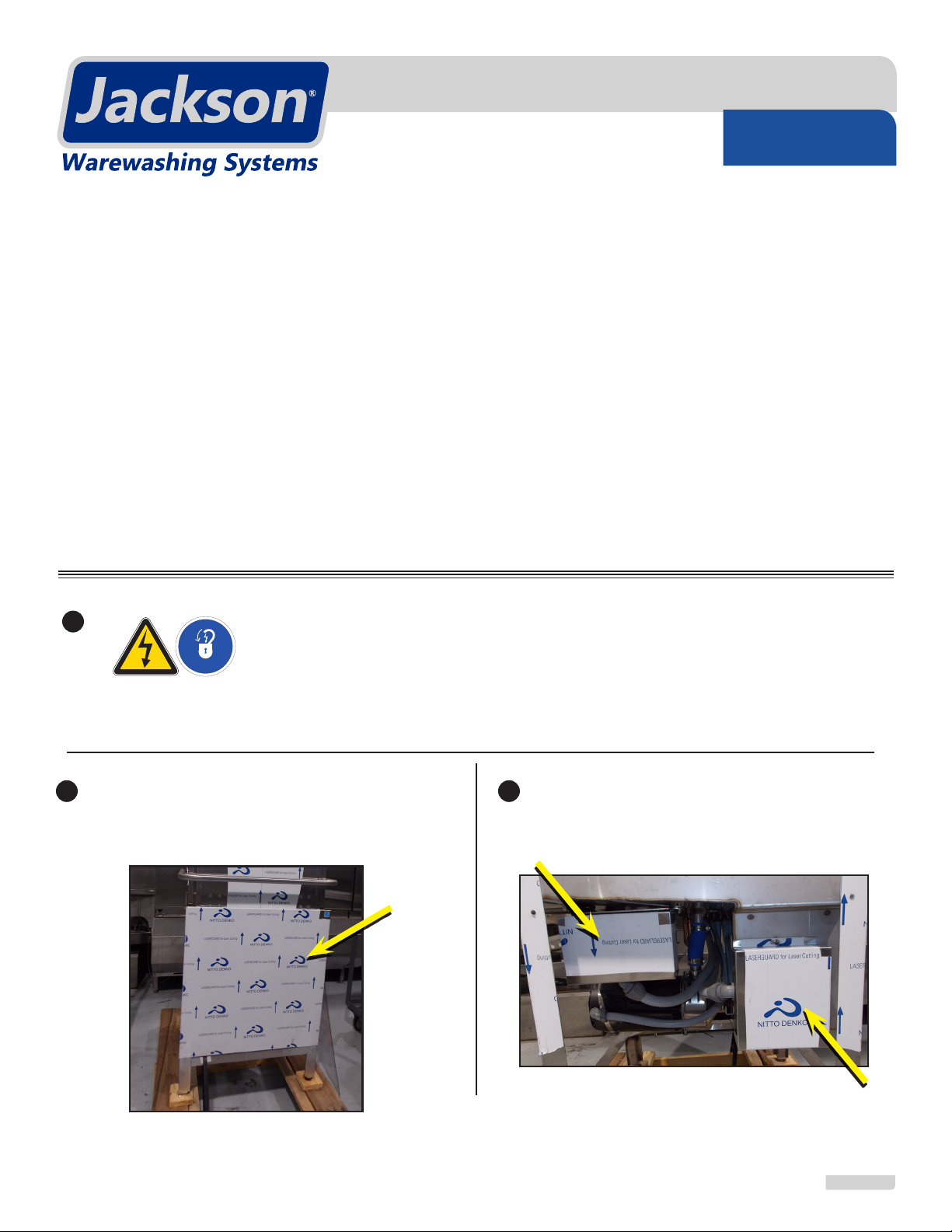
DISCONNECT ALL POWER TO THE DISHMACHINE BEFORE BEGINNING
THIS PROCESS. LOCK OUT/TAG OUT IN ACCORDANCE WITH
APPROPRIATE PROCEDURES AND CODES.
Lift up the panel and pull out gently to remove the
front dress panel.
• Step Stool
• Wire Stripper
• Needle-nose Pliers
• 3/8” Wrench (covers)
• 7/16” Wrench (probe)
32
Remove both wash and rinse heater covers using
a 3/8” wrench.
07610-004-22-11-B
1 of 12
Page 2
THERMOSTAT RETROFIT INSTRUCTIONS
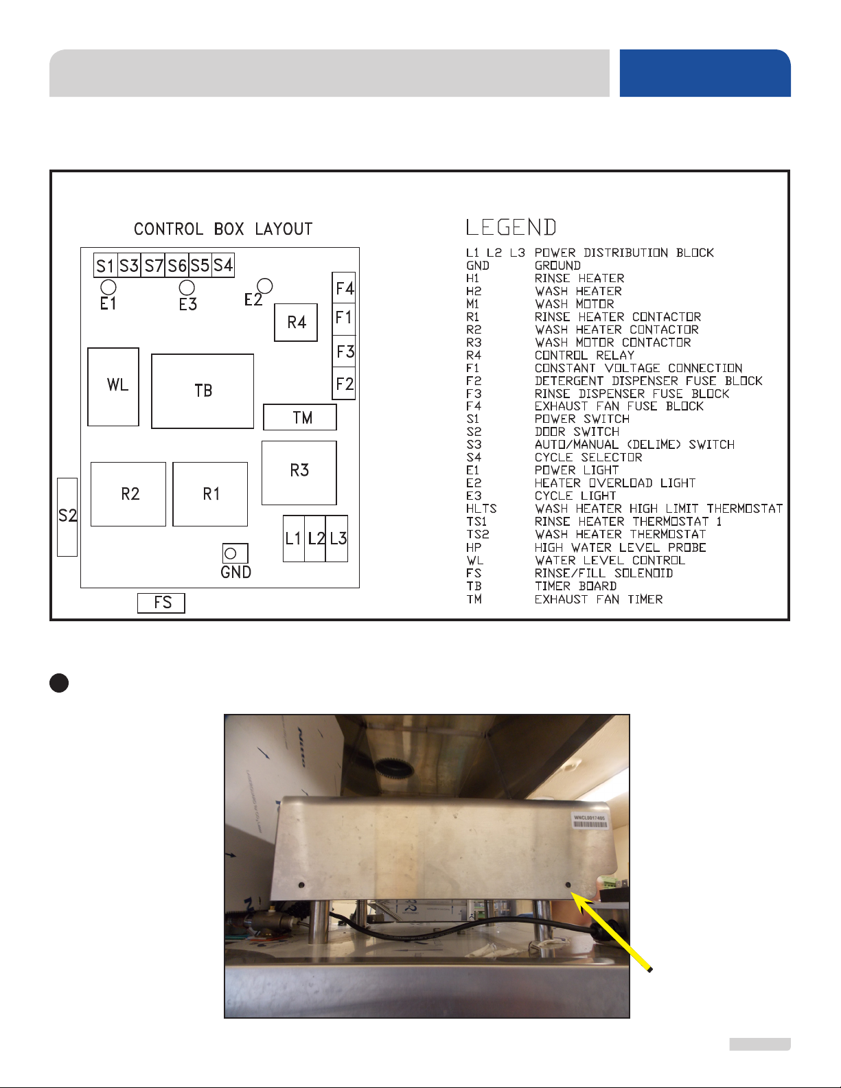
CONTROL BOX SECTION
Front
TEMPSTAR
4
Using a phillips screwdriver, remove the top panel from the control box.
07610-004-22-11-B
Screw Holes
2 of 12
Page 3
THERMOSTAT RETROFIT INSTRUCTIONS
5
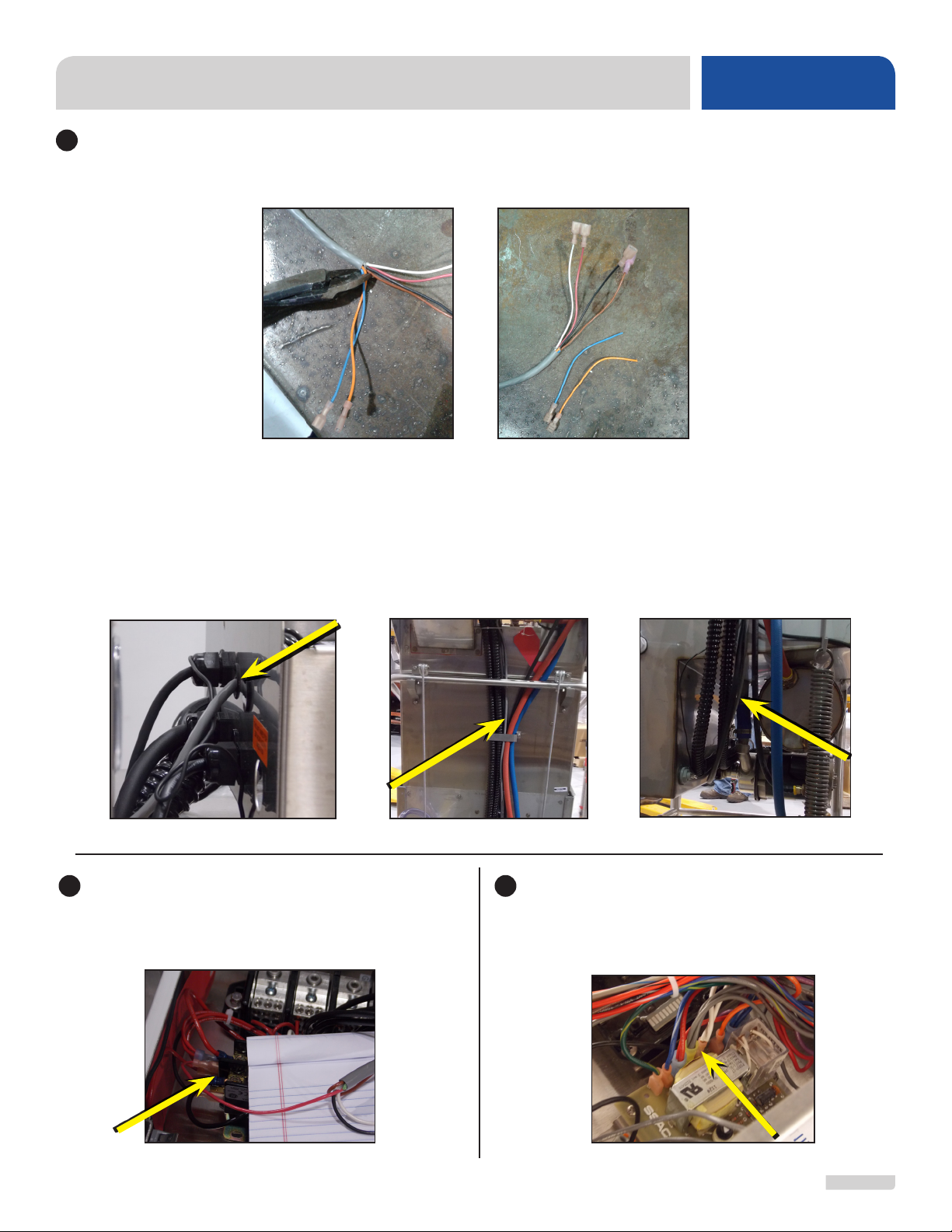
Get the gray 6-conductor cable from the retrot kit. Cut the orange and blue wires off at the edge of the gray
sheath and discard those orange and blue segments. Notice that one end has all female terminals (this is the
bottom portion) and the other end has one male and the three females (this is the top portion).
The gray cable is to be routed from the top of the unit and trail down to the wash heater area. Pop out a black
blank on the back of the control box and insert a new grommet from the retrot kit. Insert the top portion of the
gray cable (with the male and female terminals) through the grommet on the back of the control box (leave
approx. 12” up in the control box). Run the gray cable down the back of the machine. Make sure to run the
wire under the bracket and bar in the back so it is not hanging loose. Underneath the unit, route the gray
cable between the wash tank and rinse booster. Once entering the wash tank heater housing area, route the
gray cable over the high-limit switch.
TEMPSTAR
In the control box, attach the red wire from the
6-conductor cable to the open tab on the L2 side
of the Wash Motor Contactor (R3).
07610-004-22-11-B
76
Locate and remove the two white wires in the
single terminal on the Water Level Controller
(WL) at the #1 position. Cut the terminal off of
the two white wires.
3 of 12
Page 4
THERMOSTAT RETROFIT INSTRUCTIONS
8
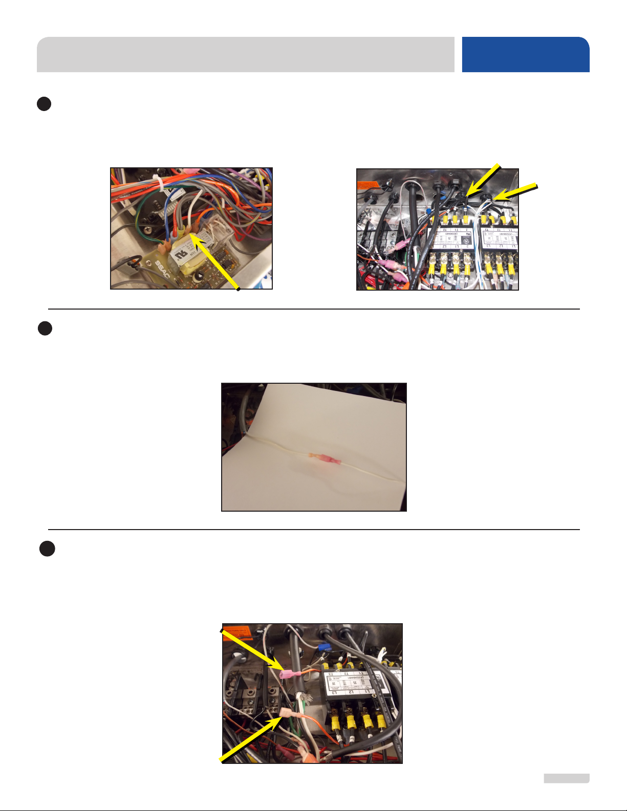
Trace the two white wires to the back of the control box. On the white wire that enters the wash conduit (from
the front of the box, it is the conduit on the far right), strip and crimp a red female terminal onto the end and
connect it back to the Water Level Controller at the #1 position where it was removed in Step 7.
Rinse Conduit
9
Trace the other white wire that was removed in Step 7 to the rinse conduit (from the front, it is the conduit
to the immediate left of the wash conduit). Strip and crimp a red male terminal onto the white wire and then
connect it to the white wire from the 6-conductor cable.
TEMPSTAR
Wash Conduit
10
Locate the orange/white wire coming out of rinse conduit (same conduit as located in Step 9) and note it
ends with a termination into the Rinse Heater Contactor (R1). Cut the orange/white wire approximately
midway between the rinse conduit and the rinse heater contactor (R1). Strip and crimp a red male terminal
on the end that goes to the rinse conduit and a red female on the end that goes to the rinse heater contactor.
07610-004-22-11-B
4 of 12
Page 5

THERMOSTAT RETROFIT INSTRUCTIONS
TEMPSTAR
11
Connect the orange/white wire from the rinse
conduit to the black wire from the 6-conductor
cable.
13
Re-attach the control box cover with the phillips-head screws.
RINSE BOOSTER SECTION
12
Connect the orange/white wire from the rinse
heater contactor to the brown wire from the
6-conductor cable.
14
Find the thermostat on the rinse booster tank. Disconnect the orange/white and white wires from the
rinse thermostat.
15
Cut ring terminals off both the orange/white and white wires. Strip wires and crimp each with red male
terminals.
07610-004-22-11-B
5 of 12
Page 6

THERMOSTAT RETROFIT INSTRUCTIONS
WARNING: Make sure machine has had time to let water in the booster tank cool.
!
WARNING
16
Prepare the new probe with the imperial brass tting before removing the existing thermostat. Remove
rinse thermostat. Use 7/16" wrench on tting behind the thermostat. After tting is loosened, pull out on
the thermostat until the probe is removed from the wash tank.
IF WATER IS NOT COOL, THE WATER TEMPERATURE COULD CAUSE SERIOUS BURNS.
Place a bucket under the booster before the thermostat is removed to catch the water.
If step 16 and 17 are done rapidly, minimal water will drain from the booster tank.
TEMPSTAR
17
Slide new ¼” Imperial brass tting onto the new rinse probe that is included in the retrot kit. Probe slides
into the hole the same way the other came out. Tighten tting on probe with a 7/16” wrench, making sure
to leave ¼” of the probe exposed.
18
Connect the orange/white wire to the black/white wire from the rinse probe. Connect white wire to the
black wire from the rinse probe. Use a zip-tie to straighten-up the wires.
19
Reattach the rinse cover with the 3/8” wrench.
07610-004-22-11-B
6 of 12
Page 7

THERMOSTAT RETROFIT INSTRUCTIONS
WASH TANK SECTION
TEMPSTAR
20
Disconnect white/red wire from wash thermostat
as well as from the high-limit switch. Remove wire
completely and discard.
Cut ring terminal off the white/yellow wire; strip and crimp a red female terminal to the white/yellow wire.
22
WARNING: Make sure that the drain stopper has been
!
WARNING
THE WATER TEMPERATURE COULD CAUSE SERIOUS BURNS.
Remove wash thermostat. Use 7/16” wrench on tting behind the thermostat. After tting is loosened, pull
23
out on the thermostat until the probe is removed from the wash tank.
removed and that the wash tank is drained.
21
Disconnect white/yellow wire from wash
thermostat.
Removed Thermostat
Probe
Imperial Brass Fitting
24
Slide new ¼” Imperial brass tting onto the new wash probe that is included in the retrot kit. Probe slides
into the hole the same way the other came out. Tighten tting on probe with a 7/16” wrench; make sure to
leave ¼” of the probe exposed (a bracket ts over the probe in later steps, be sure that only 1/4" of the probe
is exposed or the bracket will not t correctly).
07610-004-22-11-B
7 of 12
Page 8

THERMOSTAT RETROFIT INSTRUCTIONS
25
Using a 5/16” nut driver, remove the two nuts securing the high-limit switch (nuts used later to reattach). Be
careful with the thin tubing coiled behind the high-limit switch as you remove the switch and bracket from
the studs.
Place new thermostat mounting bracket (from retrot kit) onto the two studs where the high limit switch was
26
removed.
TEMPSTAR
Reposition the coil of thin tubing on top of the mounting bracket and then fasten the high limit switch (with
the same nuts) on top of the mounting bracket to the same studs where it was attached before.
27
Install the new thermostat onto the mounting bracket using the #6 – 32 screws provided in the kit. Make sure
thermostat is congured so that the 5-pin connector is at the bottom.
07610-004-22-11-B
8 of 12
Page 9

THERMOSTAT RETROFIT INSTRUCTIONS
28
Connect the 4-pin and 5-pin connectors to the thermostat.
Connect the white/yellow wire removed earlier from the high-limit switch (Step 22) onto the white/yellow wire
29
(slot 3) from the 4-pin connector.
Locate the white wire in slot 4 of the 4-pin
30
connector. It has a blue female terminal and is
attached to a white jumper. Plug that blue female
terminal into the L1 tab on the thermostat.
31
Locate the white wire located in slot 2 of the
4-pin connector. It has a blue female terminal
and is attached to the same jumper as described
in step 30. Plug that blue female terminal into the
top position (normally closed) on the high-limit
switch.
TEMPSTAR
Locate the white/red wire (slot 1) on the 4-pin
32
connector. Connect that to the brown wire from
the 6-conductor cable.
07610-004-22-11-B
Connect the red wire from the 6-conductor cable
33
to the L2 tab on the thermostat.
9 of 12
Page 10

THERMOSTAT RETROFIT INSTRUCTIONS
TEMPSTAR
Connect the black wire from the 6-conductor
34
cable to the orange/white wire (slot 5) of the 5-pin
connector.
Connect the black wire from the probe to the
36
black wire (slot 2) of the 5-pin connector.
Connect the white wire from the 6-conductor cable
35
to the white wire (slot 4) of the 5-pin connector.
Connect the black/white wire from the probe
37
to the black/white wire (slot 1) of the 5-pin
connector.
38
Using a zip-tie, coil up and secure the black and black/white wires from the 5-pin connector and probe.
07610-004-22-11-B
10 of 12
Page 11

THERMOSTAT RETROFIT INSTRUCTIONS
39
Adjust the settings for the thermostat as follows: set dip switch #1 (rinse) to the 1 position (1 set toward the
"ON" position and 2, 3, 4 set away from the "ON" position). Set dip switch #2 (wash) to the 3 position (3 set
toward the "ON" position and 1, 2, 4 set away from the "ON" position). Note: the switches can be moved
with either a ngernail or control screwdriver through the protective lm.
Blue dials should all be set as indicated in the picture below (or mid-position between the two stops).
TEMPSTAR
Replace standpipe and strainer.
40
Adjust the 1st knob (left knob) until the desired
42
rinse temperature is achieved (between 180 °F
and 195 °F for the entire rinse cycle). Clockwise
= increase temperature. Total adjustment is ±10
°F.
Turn power on to the machine, turn the power
41
switch to the “ON” position, and wait until tanks
heat to setpoint. Run the unit three cycles and
check rinse and wash temperature.
Adjust the 2nd knob (right knob) until 150 °F wash
43
temperature is achieved. Clockwise = increase
temperature. Total adjustment is ±10 °F.
07610-004-22-11-B
11 of 12
Page 12

THERMOSTAT RETROFIT INSTRUCTIONS
Attach new wash heater cover. Adjust strain relief and tighten once in position. Replace front dress panel.
44
TEMPSTAR
07610-004-22-11-B
12 of 12
 Loading...