

Page 1
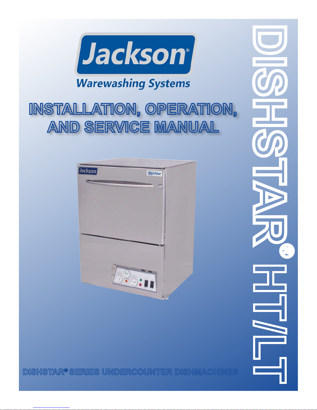
INSTALLATION, OPERATION,
AND SERVICE MANUAL
DISHSTAR
DISHSTAR® SERIES UNDERCOUNTER DISHMACHINES
DishStar® HT/LT Manual • 07610-004-37-13-E
HT/LT
®
Page 2

Page 3

MANUFACTURER'S WARRANTY
ONE YEAR LIMITED PARTS AND LABOR WARRANTY
ALL NEW JACKSON DISHWASHERS ARE WARRANTED TO THE ORIGINAL PURCHASER TO BE FREE FROM DEFECTS IN
MA TERIAL OR WORKMANSHIP, UNDER NORMAL USE AND OPERATION, FOR A PERIOD OF (1) ONE YEAR FROM DATE OF
PURCHASE, BUT IN NO EVENT TO EXCEED (18) EIGHTEEN MONTHS FROM DATE OF SHIPMENT FROM THE F ACTORY.
Jackson WWS agrees under this warranty to repair or replace, at its discretion, any original part which fails under normal use
due to faulty m aterial or workmanship during the warranty period, providing the equipment has been unaltered, and has been
properly instal l e d , mainta i n ed, and operated in accordance with the applicable factory instruction manual and failure is reported
to an authorized service agency within the warranty period. This includes the use of factory-specied genuine replacement parts,
purchased directly from a Jackson-authorized parts distributor or service agency. Use of generic replacement parts may create a
hazard and void warranty certication.
The labor to repair or replace such failed part will be paid by Jackson WWS, within the continental United States, Hawaii, and Canada,
during the warranty period provided a Jackson WWS authorized service agency , or those having prior authorization from the factory,
performs the service. Any repair work by persons other than a Jackson WWS authorized service agency is the sole responsibility of
the customer. Labor coverage is limited to regular hourly rates; overtime premiums and emergency service charges will not be paid
by Jackson WWS.
Accessory components not installed by the factory carry a (1) one year parts warranty only . Accessory components such as table limit
switches, pre-rinse units, etc. that are shipped with the unit and installed at the site are included. Labor to repair or replace these
components is not covered by Jackson WWS.
This warranty is void if failure is a direct result from shipping, handling, re, water, accident, misuse, acts of God, attempted repair by
unauthorized persons, improper installation, if serial number has been removed or altered, or if unit is used for a purpose other than
originally intended.
TRAVEL LIMITATIONS
Jackson WWS limits warranty travel time to (2) two hours and mileage to (100) one-hundred miles. Jackson WWS will not pay for
travel time and mileage that exceeds this, or any additonal fees—such as those for air or boat travel—without prior authorization.
WARRANTY REGISTRATION
T o register your product, go to www .jacksonwws.com or call 1-888-800-5672. Failure to register your product will void the warranty.
REPLACEMENT PARTS WARRANTY
Jackson replacement parts are warranted for a period of (90) ninety days from date of installation or (180) one-hundred-eighty
days from the date of shipment from the factory, whichever occurs rst.
PRODUCT CHANGES AND UPDATES
Jackson WWS reserves the right to make changes in the design and specication of any equipment as engineering or necessity
requires.
THIS IS THE ENTIRE AND ONLY WARRANTY OF JACKSON WWS. JACKSON’S LIABILITY ON ANY CLAIM OF ANY KIND,
INCLUDING NEGLIGENCE, WITH RESPECT TO THE GOODS OR SERVICES COVERED HEREUNDER, SHALL IN NO CASE
EXCEED THE PRICE OF THE GOODS OR SERVICES OR PART THEREOF WHICH GIVES RISE TO THE CLAIM.
THERE ARE NO WARRANTIES, EXPRESSED OR IMPLIED, INCLUDING FOR FITNESS OR MERCHANTABILITY, THAT ARE
NOT SET FORTH HEREIN, OR THAT EXTEND BEYOND THE DURATION HEREOF. UNDER NO CIRCUMSTANCES WILL
JACKSON WWS BE LIABLE FOR ANY LOSS OR DAMAGE, DIRECT OR CONSEQUENTIAL, OR FOR DAMAGES IN THE
NATURE OF PENALTIES, ARISING OUT OF THE USE OR INABILITY TO USE ANY OF ITS PRODUCTS.
ITEMS NOT COVERED
THIS WARRANTY DOES NOT COVER CLEANING OR DELIMING OF THE UNIT OR ANY COMPONENT SUCH AS, BUT NOT
LIMITED TO, WASH ARMS, RINSE ARMS, OR STRAINERS AT ANYTIME. NOR DOES IT COVER ADJUSTMENTS SUCH
AS, BUT NOT LIMITED TO, TIMER CAMS, THERMOSTATS, OR DOORS BEYOND (30) THIRTY DAYS FROM THE DATE OF
INSTALLATION. IN ADDITION, THE WARRANTY WILL ONLY COVER REPLACEMENT WEAR ITEMS SUCH AS CURTAINS,
DRAIN BALLS, DOOR GUIDES, OR GASKETS DURING THE FIRST (30) THIRTY DAYS AFTER INSTALLATION. ALSO,
NOT COVERED ARE CONDITIONS CAUSED BY THE USE OF INCORRECT (NON-COMMERICAL) GRADE DETERGENTS,
INCORRECT WATER TEMPERATURE OR PRESSURE, OR HARD WATER CONDITIONS.
Page 4
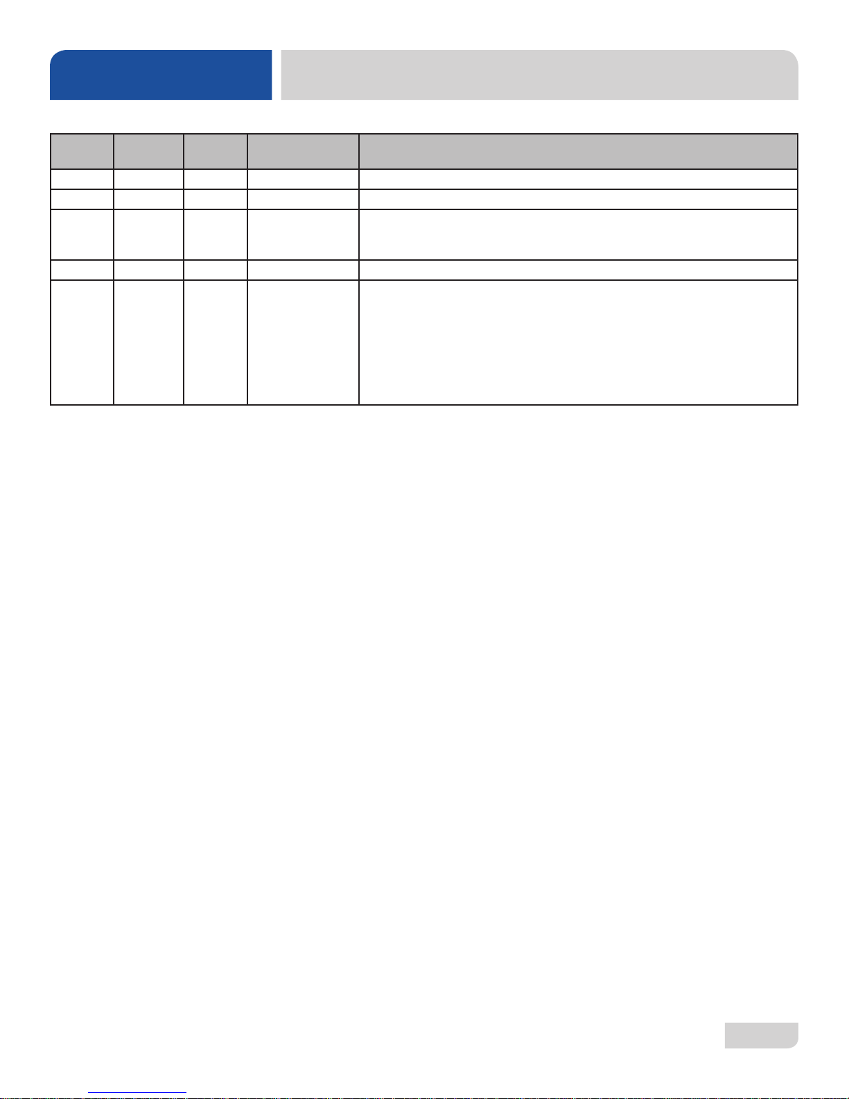
REVISION HISTOR Y
Revision
Letter
A 7-18-16 JH N/A Initial release of the manual.
B 11-30-16 JH N/A Added LT and LT-H units.
C 12-13-16 JH N/A
D 3-6-17 JH N/A Updated pg. 42 with new motor and assembly P/Ns.
E 5-16-17 JH 8511
Revision
Date
Made by Applicable ECNs Details
Updated Operating Parameters on pg. 3.
Added Drain Quench Kit and P/N to pg. 52.
Updated the Go Box kit, pg. 55.
Updated water line connection information.
Changed wording in the chemical feeder pump programming section to
indicate changes are lost if closed without saving.
Removed item #25 from pg. 47.
Changed Discharge Hose to 05700-004-43-76 in the Wash Manifold
Assembly.
Added 05700-004-36-95 to HT Display page.
Added a Plumbing Options page.
i
Page 5

NOMENCLATURE
DISHSTAR® HT
Undercounter dishmachine; high-temperature, hot-water
sanitizing, with a booster tank and
detergent and rinse-aid chemical feeder pumps.
DISHSTAR® LT
Undercounter dishmachine; low-temperature, chemical-
sanitizing, with detergent, rinse-aid, and sanitizer chemical
feeder pumps.
DISHSTAR® LT-H
Undercounter dishmachine; low-temperature with wash tank
heater, chemical-sanitizing, with detergent, rinse-aid, and
sanitizer chemical feeder pumps.
The manufacturer provides
technical support for all of
the dishmachines detailed
in this manual. We strongly
recommend that you refer to
this manual before making a call
to our technical support staff.
Please have this manual with
you when you call so that our
staff can refer you, if necessary,
to the proper page. Technical
support is not available on
holidays. Contact technical
support toll free at
1-888-800-5672.
Technical support is available
for service personnel only.
ii
Page 6

T ABLE OF CONTENTS
GUIDES
Guide to Symbols .............................................................................................................................1
Guide to Abbreviations & Acronyms .................................................................................................1
SPECIFICATIONS
Machine Dimensions ........................................................................................................................2
Operating Parameters ......................................................................................................................3
Electrical Requirements ...................................................................................................................4
INSTRUCTIONS
Installation Instructions .....................................................................................................................5
Inspection......................................................................................................................... 5
Unpacking ........................................................................................................................ 5
Plumbing .......................................................................................................................... 5
Water Supply Connections .............................................................................................. 5
Pressure Regulator .......................................................................................................... 6
Shock Absorber ............................................................................................................... 6
Connecting the Drain Line ............................................................................................... 6
Plumbing Check ............................................................................................................... 6
Electrical Power Connections .......................................................................................... 7
Voltage Check .................................................................................................................. 7
Surrounding Area ............................................................................................................. 7
Thermostats ..................................................................................................................... 7
Chemical Feeder Equipment ........................................................................................... 8
Preparing Chemical Feeder Pumps ................................................................................. 8
Priming Chemical Feeder Pumps .................................................................................... 8
Programming Chemical Feeder Pumps ........................................................................... 9
Leveling...........................................................................................................................11
Heater Contactor Wires (HT Only) ..................................................................................11
Operating Instructions ....................................................................................................................13
Preparation .................................................................................................................... 13
Filling the Wash Tub ...................................................................................................... 13
Ware Preparation ........................................................................................................... 14
Washing a Rack of Ware ............................................................................................... 14
Operational Inspection ................................................................................................... 14
Shutdown & Cleaning .................................................................................................... 14
Deliming ......................................................................................................................... 17
Detergent Control........................................................................................................... 18
MAINTENANCE
Preventative Maintenance ..............................................................................................................19
iii
Page 7

T ABLE OF CONTENTS
TROUBLE SHOOTING
Common Problems .........................................................................................................................20
PARTS
HT Control Panel ............................................................................................................................22
LT Control Panel .............................................................................................................................23
LT-H Control Panel .........................................................................................................................24
HT Display Panel ............................................................................................................................25
LT Display Panel .............................................................................................................................26
LT-H Display Panel .........................................................................................................................27
Terminal Block Box Assembly ........................................................................................................28
HT Chemical Feeder Pump Assembly ........................................................................................... 29
HT Chemical Feeder Pump Components ......................................................................................30
LT/LT-H Chemical Feeder Pump Assembly ....................................................................................31
LT/LT-H Peri-pump Track Assembly ...............................................................................................32
HT Plumbing Assemblies ............................................................................................................... 33
LT/LT-H Plumbing Assemblies ........................................................................................................35
Plumbing Options ...........................................................................................................................37
Vacuum Breaker ............................................................................................................................ 38
Wash Manifold Assembly ...............................................................................................................39
Motor & Pump Assembly ................................................................................................................41
Rinse Arm & Wash Arm Assemblies ............................................................................................... 43
Thermostat & Rinse Tank Assembly ...............................................................................................45
Door Assembly ............................................................................................................................... 46
Miscellaneous Door Components ..................................................................................................48
Frame & Panel Components ..........................................................................................................50
Miscellaneous Parts .......................................................................................................................52
Stands & Components ...................................................................................................................53
HTS-11 (Scale Prevention & Corrosion Device) ............................................................................. 54
Go Box Kit ......................................................................................................................................55
LT-H Optional Heater Components ................................................................................................56
LT/LT-H Vacuum Switch Assembly .................................................................................................57
LT/LT-H Vacuum Switch Assembly Install .......................................................................................58
SCHEMATICS
DishStar® HT 208-240 V, 50/60 Hz, 1/3 Phase ..............................................................................59
®
DishStar
LT/LT-H 115 V, 50/60 Hz, 1 Phase .................................................................................60
iv
Page 8

GUIDES
NOTICE
SYMBOLS
- risk of injury to personnel.
!
WARNING
- risk of damage to equipment.
!
CAUTION
- risk of electrical shock.
- reference data plate.
i
- caustic chemicals.
GUIDES
- ground wire.
- lockout electrical power.
- important note.
ABBREVIA TIONS & ACRONYMS
ANSI - American National Standards Institute
GHT - Garden Hose Thread
GPM - Gallons per Minute
GPG - Grains per Gallon
HP - Horse Power
Hz - Hertz
ID - Inside Diameter
kW - Kilowatts
NFPA - National Fire Protection Association
NPT - National Pipe Thread
PSI - Pounds per Square Inch
V - Volts
07610-004-37-13-E
1
Page 9
SPECIFICATIONS
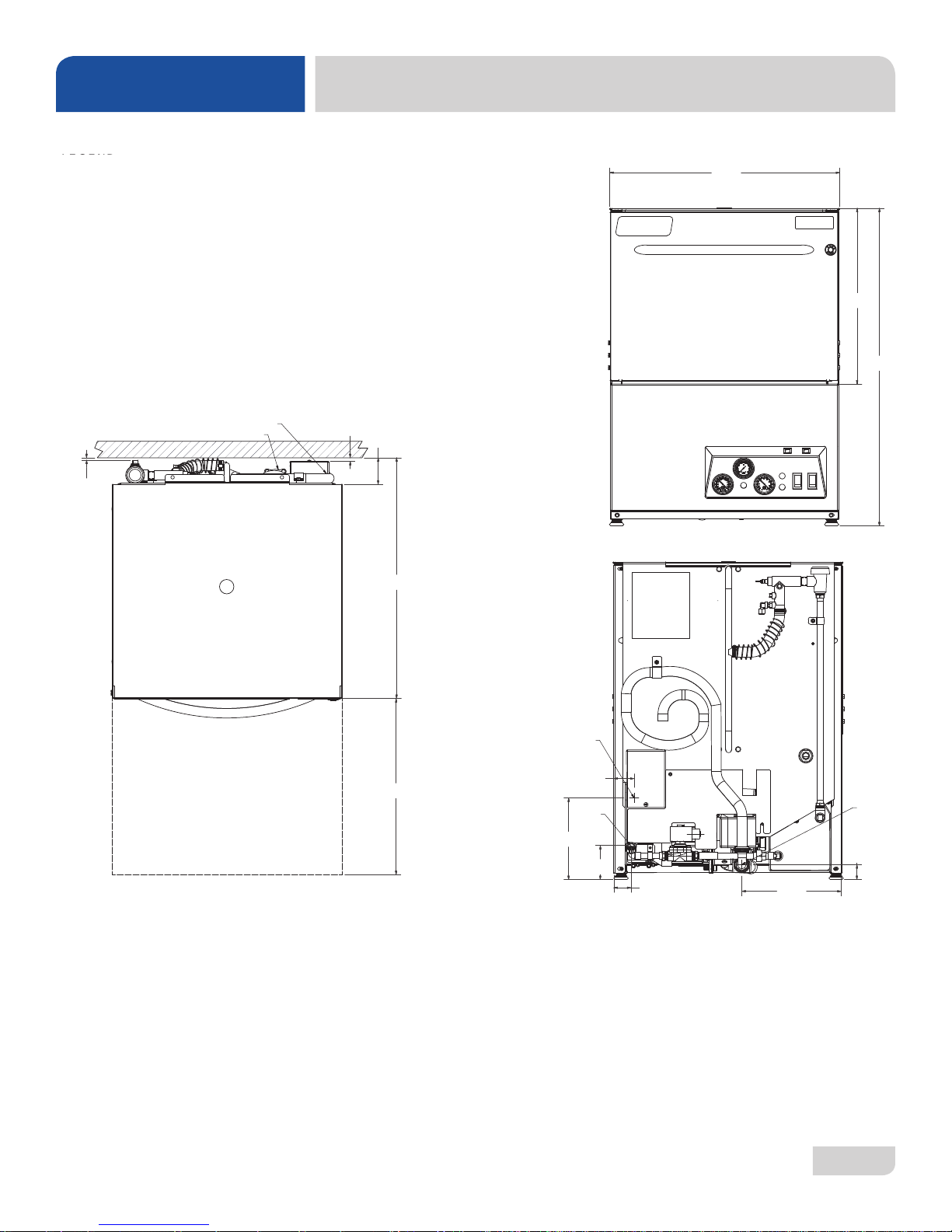
LEGEND
LEGEND
A- Water Inlet - 1/2" Female Pipe Thread
A - Water Inlet
2 -1/2" AFF (Connection to a true 1/2" ID water Line)
(3/4" Male GHT, connect to true 1/2" ID line, 110 °F minimum)
B- Electrical Connection
B- Electrical Connection
C- Drain Connection- 6' coiled Drain Hose.
Shipped inside machine. Must be installed
C - Drain Connection
no more than 24" AFF
(1" ID, 1 3/8" OD)
All dimensions from floor can be increased
1" with adjustablefeet supplied.
All dimensions from the oor can be increased 1" with the
machine's adjustable feet.
MACHINE DIMENSIONS
24 3/16"
(615 mm)
FRONT
18 1/2"
(470 mm)
33 5/16"
(846 mm)
1/4"
(7 mm)
Wall Clearance
TOP
B
A
3/8"
(1 mm)
2 3/4"
(70 mm)
BACK
52 3/8"
(1330 mm)
B
2 1/8"
8 5/8"
(220 mm)
(54 mm)
(18 mm)
A
3 5/8"
1 7/8"
(48 mm)
10 1/2"
(267 mm)
1 5/8"
(41 mm)
C
18 1/2"
(470 MM)
*All dimensions are for reference only and are subject to change without notice.
07610-004-37-13-E
2
Page 10

SPECIFICATIONS
NOTICE
OPERATING PARAMETERS
Operating Capacity: HT LT/LT-H
Racks per Hour 24 24
Dishes per Hour 600 600
Glasses per Hour 864 864
Gallons per Rack 1.1 1.2
Gallons per Hour 26.4 28.8
Tank Capacity (Gallons):
Wash Tank 1.1 1.2
Rinse Tank 3.0 N/A
Electrical Loads (as applicable):
Wash Motor HP 1.0 1.0
Rinse Heater kW 6.7 (208 V)/8.2 (230 V) N/A
Wash Heater kW N/A 1.5
NOTE: Always refer to the machine data plate for specic electrical and
water requirements. The material provided on this page is for reference
only and is subject to change without notice.
i
HOT WATER SANITIZING
Water Temperatures (°F):
Minimum Wash Temperature 150 N/A
Minimum Rinse Temperature 180 N/A
Minimum Incoming Water Temperature 110 N/A
CHEMICAL SANITIZING
Water Temperatures (°F):
Minimum Wash Temperature N/A 120
Minimum Rinse Temperature N/A 120
Minimum Incoming Water Temperature N/A 120
Other Water Requirements:
Water Flow Pressure (PSI) 20 ± 5 20 ± 5
Flow Rate Minimum (GPM) 6.6 6.6
Water Line Connection Size (NPT) 3/4" GHT 3/4" GHT
Water Line Size (NPT) 1/2" 1/2"
Drain Line Size (NPT) 1" ID 1" ID
1 3/8" OD 1 3/8" OD
Minimum Chlorine Required (PPM) N/A 50
07610-004-37-13-E
3
Page 11
NOTICE
SPECIFICATIONS
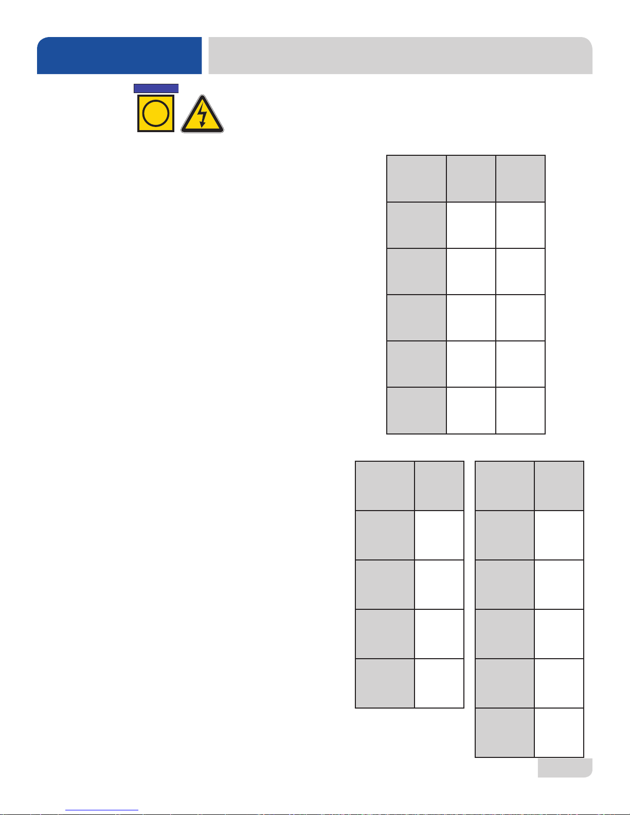
ELECTRICAL REQUIREMENTS
i
All electrical ratings provided in this manual are for reference
only . Always refer to the machine data plate to get exact electrical
information for this machine. All electrical work performed on
machines should be done in accordance with applicable
local, state, territorial, and national codes. Work should only
be performed by qualied electricians and authorized service
agents.
Note that all electrical wiring used in the DishStar® series of
machines must be rated, at a minimum, for 212 °F (100 °C), and
that only copper conductors must be used.
Where applicable, heating element amperage draws have been
adjusted for the assumed input voltage. The manufacturer
assumes incoming voltages will be either 208 or 230 Volts. Some
heating elements used in the machines are rated for other voltages,
such as 240 Volts and 480 Volts. Always verify the amperage
draw of the machine in operation when sizing circuit protection.
If the dishmachine is equipped with the optional rinse heater, note
the rinse heater might have its own electrical connection and
require a separate service. Amperage loads for motors and heaters
are indicated on the machine data plate.
Electrical Characteristics
DishStar® HT
VOLTS 208 230
PHASE 1 1
FREQ 60 60
WASH
MOTOR
AMPS
RINSE
HEATER
AMPS
TOTAL
LOAD
DishStar® LT
5.0 A 5.0 A
32.2 A 35.7 A
37.2 A 40.7 A
DishStar
®
LT-H
The electrical congurations of the DishStar
are as follows:
Available Electrical Characteristics:
HT
• 208 V, 60 Hz, Single-phase
• 230 V, 60 Hz, Single-phase
LT/LT-H
• 115 V, 60 Hz, Single-phase
Available Wash Tank Heaters:
• 1.5 kW (LT-H Only)
*The DishStar® LT-H is designed so that the wash motor is never
running when the wash heater is on. Total Load is based on the
higher of the two loads.
07610-004-37-13-E
®
series of machines
VOLTS 115
PHASE 1
FREQ 60
WASH
MOTOR
AMPS
TOTAL
LOAD
5.0 A
5.0 A
VOLTS 115
PHASE 1
FREQ 60
WASH
MOTOR
AMPS
WASH
HEATER
AMPS
TOTAL
LOAD
5.0 A
13.1 A
13.1 A*
4
Page 12

INSTALLATION
INSTRUCTIONS
INSPECTION
Do not throw away
container if damage is
evident!
UNPACKING
PLUMBING
The plumber must ush
the incoming water line!
Before installing the unit, check packaging and machine for damage. Damaged
packaging might be an indication of damage to the machine. If there is any type
of damage to both packaging and unit, do not throw away the packaging. The
dishmachine has been inspected at the factory before shipping and is expected to
arrive in new, undamaged condition. However, rough handling by carriers or others
might result in damage to the unit while in transit. If this occurs, do not return the unit to
the manufacturer. Instead, contact the carrier and ask them to send a representative
to the site to inspect the damage and request that an inspection report be completed.
Contact the carrier within 48 hours of receiving the machine as well as the dealer that
sold you the unit.
The machine should be unboxed and removed from the pallet before installing. Open
the front door and remove all of the materials from inside. Once unpacked, verify there
are no missing parts. If a part is missing, contact the manufacturer immediately.
All plumbing connections must be made to adhere to local, state, territorial, and
national codes. The installing plumber is responsible for ensuring the incoming
water lines are ushed of debris before connecting to the machine. Note that chips
and materials from cutting processes can become lodged in the solenoid valves
and prevent them from opening or closing. Any valves that are found to be fouled
or defective because of foreign matter left in the water line, and any subsequent
damage, are not the responsibility of the manufacturer.
A water hardness test
must be performed.
WATER SUPPLY
CONNECTIONS:
WATER HARDNESS
HIGHER THAN
5 GPG
07610-004-37-13-E
A water hardness test must be performed. A hardness test kit can be found on the
warning tag that is attached to the incoming plumbing connection on the back of the
machine. If water hardness is higher than 5 GPG, install a water softener or install the
optional HTS-11 (scale prevention and corrosion control). See the Plumbing Options
page for more information on the HTS-11.
If water hardness is higher than 5 GPG and a water softener is not being used, install
the HTS-11 into the water line (1/2” ID pipe size minimum) before the machine’s
incoming water connection point using copper pipe. Observe proper inlet/outlet water
directions (ow directions are molded into the top of the head). It is recommended
that a water shut-off valve be installed before installing the HTS-1 1 to allow access for
service. Plumb from the HTS-11 outlet to the incoming water connection point using
copper pipe (or order the 1/2” ID exible hose kit offered by manufacturer). The water
supply must be capable of a minimum of 10 PSI “ow” pressure at the recommended
temperature indicated on the data plate. See the Plumbing Options page for more
information on the HTS-11.
5
Page 13

INSTALLATION
INSTRUCTIONS
WATER SUPPLY
CONNECTION:
WATER HARDNESS
OF 5 GPG
OR LOWER
PRESSURE
REGULATOR
Take care not to confuse
static pressure with
ow pressure!
SHOCK ABSORBER
If water hardness tests at 5 GPG or lower, install the water supply line (1/2” ID pipe
size minimum) to the machine’s incoming water connection point using copper pipe
(or order the 1/2” ID exible hose kit offered by the manufacturer). It is recommended
that a water shut-off valve be installed in the water line between the main supply and
the machine to allow access for service. The water supply line must be capable of a
minimum of 10 PSI “ow” pressure at the recommended temperature indicated on the
data plate.
The manufacturer has an optional water pressure regulator to accommodate areas
where water pressure uctuates or is higher than the recommended pressure. Take
care not to confuse static pressure with ow pressure: static pressure is line pressure in
a “no ow” condition (all valves and services are closed); ow pressure is the pressure
in the ll line when the valve is opened during the cycle. See the Plumbing Options
page.
It is sug gest ed t hat a sh ock a bso rbe r (not supplied) be installed on the incoming water
line. This prevents water hammer (hydraulic shock)—induced by the solenoid valve
as it operates—from causing damage to the equipment. See the Plumbing Options
page.
CONNECTING THE
DRAIN LINE
PLUMBING CHECK
The dishmachine has a pumped (pressure) drain capable of pumping waste water
to a height of 24” above the oor to the kitchen’s drain system. Each dishmachine is
supplied with a drain hose. When installed, it will extend from the rear side of the ma-
chine. There must be an air-gap between the machine drain line and the oor sink or
drain. If a grease trap is required by code, it should have a ow capacity of 12 GPM.
After installing the incoming ll line and the drain line, slowly turn on the water supply
to the machine. Check for any leaks and repair as required. All leaks must be
repaired before operating the machine.
07610-004-37-13-E
6
Page 14
INSTALLATION
NOTICE
INSTRUCTIONS
ELECTRICAL POWER
CONNECTIONS
Disconnect electrical
power at the breaker or
disconnect switch and
tag-out in accordance with
procedures and codes.
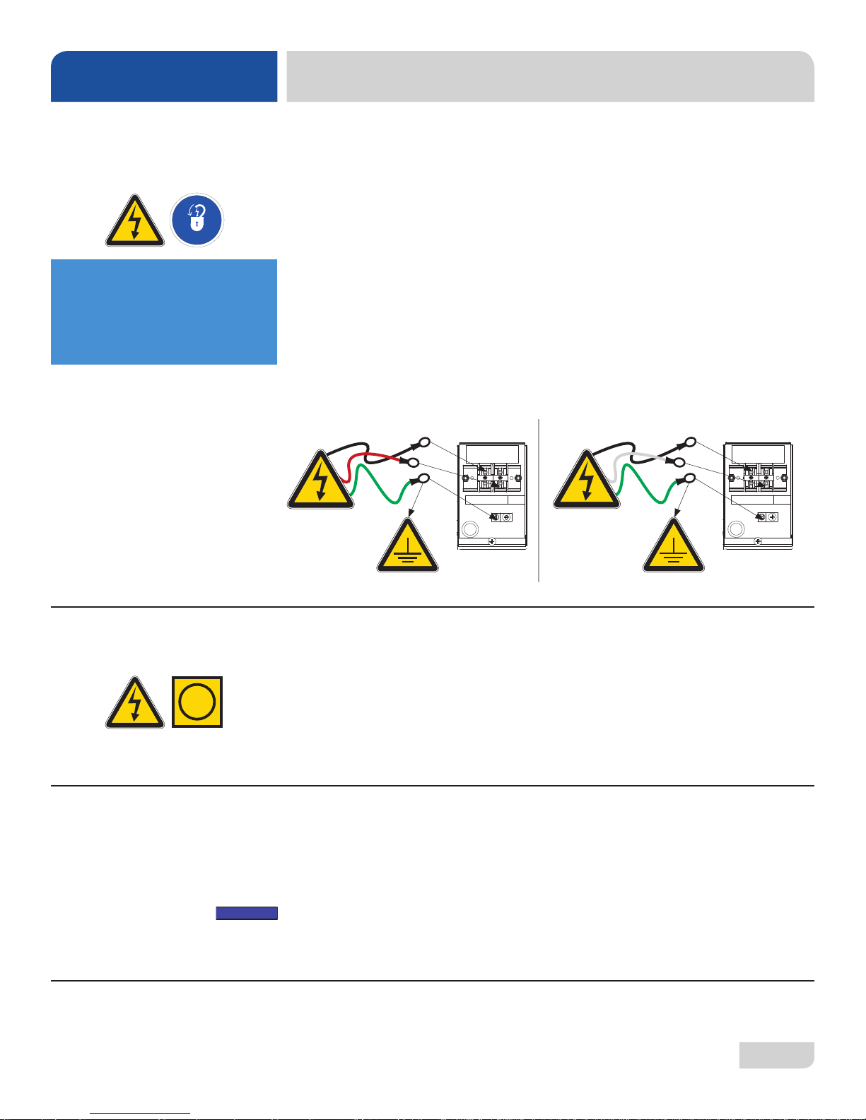
Electrical and grounding conductors must comply with the applicable portions of the
National Electric Code ANSI/NFPA 70 (latest edition) and/or other electrical codes.
The data plate is located at the left-front side of the dishmachine. Refer to the data plate
for machine operating requirements, machine voltage, total amperage, and serial number.
Remove the back panel and set aside. This will require removing the screw at the
bottom of the back panel with a phillips screwdriver. Install 3/4” conduit into the prepunched holes in the back of the control box. Route power wires and connect to power
block and grounding lug. Install the service wires (L1 and L2 for HT, L1 and N for LT/
LT-H) to the appropriate terminals as they are marked on the terminal block. Install
the grounding wire into the lug provided. It is recommended that “DE-OX” or another
similar anti-oxidation agent be used on all power connections.
HT LT/LT-H
L1 L2
GRND
L1 N
GRND
VOLT AGE CHECK
i
SURROUNDING
AREA
THERMOSTATS
Ensure that the "ON/OFF" switch is in the "OFF" position and apply power to
dishmachine. Check the incoming power at the terminal block and ensure it
corresponds with the voltage listed on the data plate. If not, contact a qualied service
agency to examine the problem. Do not run dishmachine if voltage is too high or too
low. Shut-off the service breaker and advise all proper personnel of the location of
the breaker and any problems. Replace the control box cover and tighten-down the
screws.
This is a commercial dishmachine and reaches temperatures that can exceed
those generated by a residential machine. Surrounding countertops, cabinets, ooring
material, and suboor material must be designed and/or selected with these higher
temperatures in mind.
NOTE: Any damage to surrounding area that is caused by heat and/or moisture
to materials that are not recommended for higher temperatures will not be covered
under warranty or by the manufacturer.
The thermostats on this dishmachine have been set at the factory. They should only
be adjusted by an authorized service agent.
07610-004-37-13-E
7
Page 15
INSTALLATION
INSTRUCTIONS
CHEMICAL FEEDER
EQUIPMENT
PREPARING
CHEMICAL FEEDER
PUMPS
CAUTION! Chlorine-based sanitizers can be detrimental to this
!
CAUTION
The bottom of the chemical container cannot be located any higher than 8” from the
oor. If the unit is equipped with the 6” or 18” table stand, the highest position will be
14” or 26” from the oor, respectively. It is important to remember that if you decide
to operate the unit in chemical-sanitizing mode, you must ensure an appropriate
chlorine-based sanitizer is used in the nal rinse line.
The DishStar® HT dishmachine is supplied with detergent and rinse-aid chemical
feeder pumps.
The DishStar® LT and LT-H dishmachines are supplied with detergent, rinse-aid, and
sanitizer chemical feeder pumps.
Locate the open ends of the chemical tubes with the tube stiffeners and place each
one in the appropriate container.
A. Red Tubing = Detergent B. Blue Tubing = Rinse-Aid
C. White Tubing = Sanitizer
machine if the chemical solution is too strong. See a chemical
professional to ensure the dispenser is set-up correctly .
PRIMING CHEMICAL
FEEDER PUMPS
!
WARNING
WARNING: Some of the
chemicals used in
dishwashing might cause
chemical burns if they
come in contact with skin.
Wear protective gear when
handling these chemicals.
If any contact with skin
occurs, immediately
follow the treatment
instructions provided
with the chemicals.
Chemical feeder pumps need priming when the machine is rst installed or if the
chemical lines have been removed and air is allowed to enter.
!
CAUTION
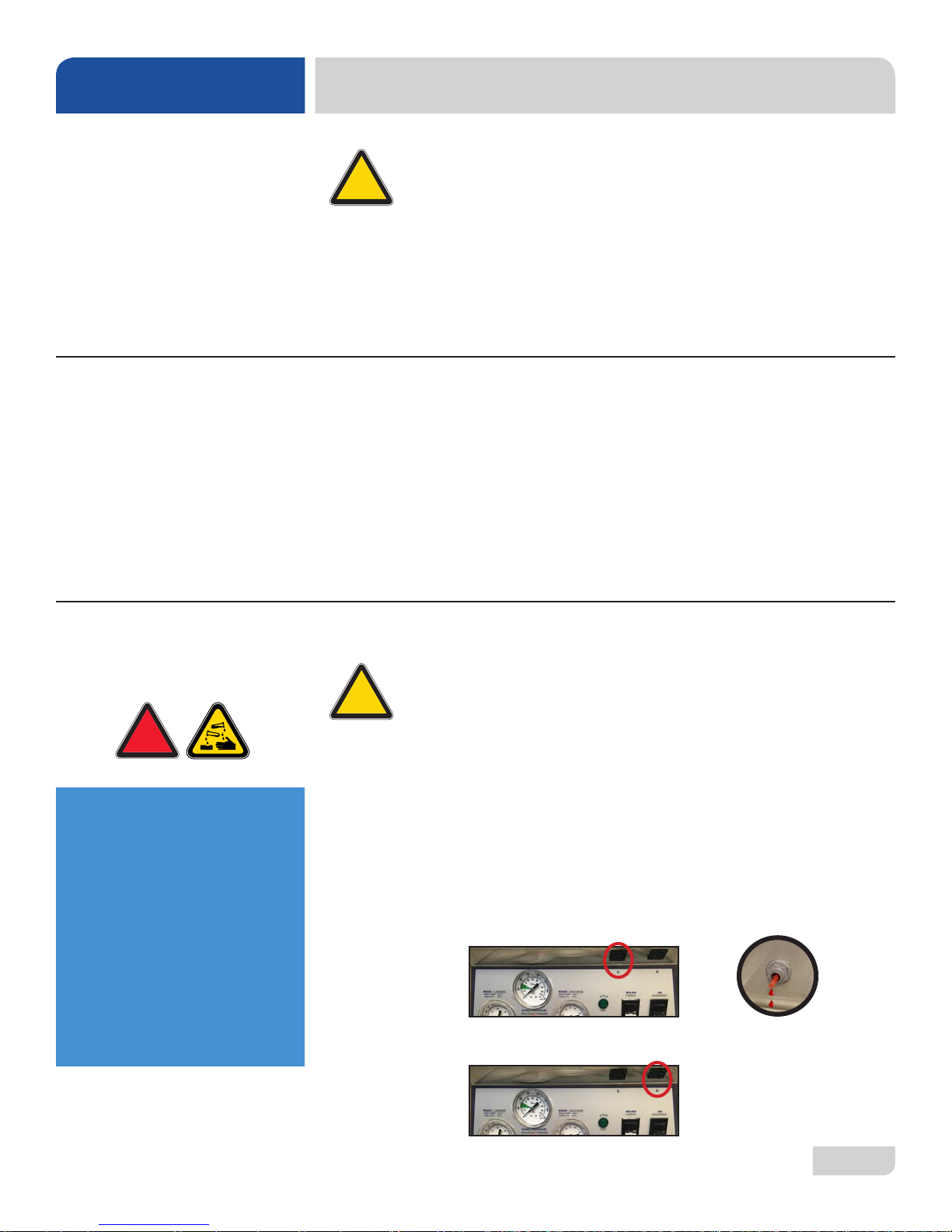
1. Verify that the proper chemical tube stiffener inlet is in the proper container.
2. Use the prime switches located on the control panel at the bottom of the unit to
prime each pump. The switches are clearly marked, "D" for detergent and "R"
for Rinse-aid.
3. To prime the pumps:
HT
• Detergent - hold the "D" switch in the momentary position until detergent is
• Rinse-aid - hold the "R" switch in the momentary position for one minute.
CAUTION! Water must be in the sump and wash tank before chemicals
are dispensed.
seen entering the wash tank.
07610-004-37-13-E
8
Page 16
INSTALLATION
INSTRUCTIONS
PRIMING CHEMICAL
FEEDER PUMPS
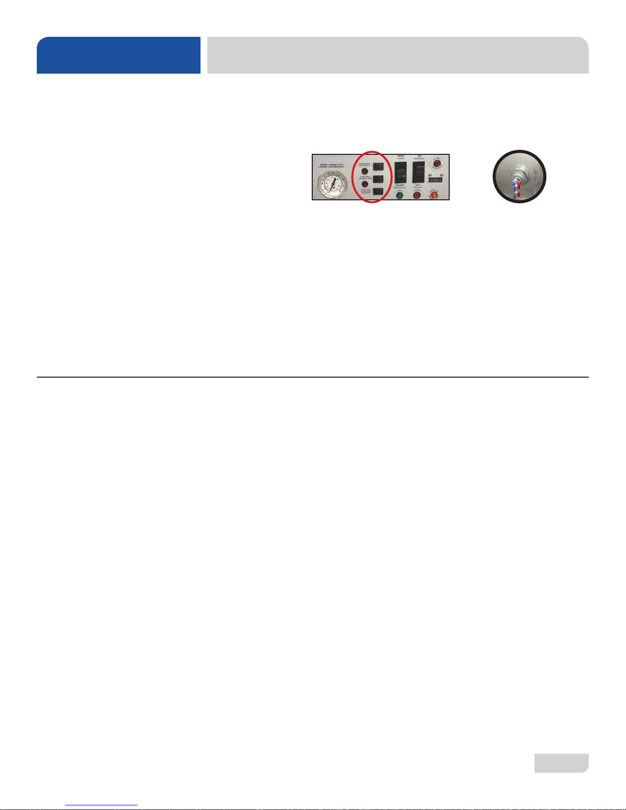
LT/LT-H
• Detergent, Rinse-aid, and Sanitizer - hold each priming switch until the
respective chemical can be seen entering the wash tank.
4. Detergent is dispensed as required during the wash cycle by the timer. The
amount of detergent might need to be increased or decreased depending upon
water quality and type of detergent.
5. Rinse-aid is dispensed as required into the nal rinse. The amount of rinse-aid
might need to be adjusted depending upon water hardness and results.
6. Sanitizer is dispensed proportionally into the nal rinse water line. The amount
of sanitizer might need to be adjusted depending on concentration.
7. Please refer to the instructions below on adjusting the chemical feeder pumps
on the universal timer.
PROGRAMMING
CHEMICAL
FEEDER PUMPS
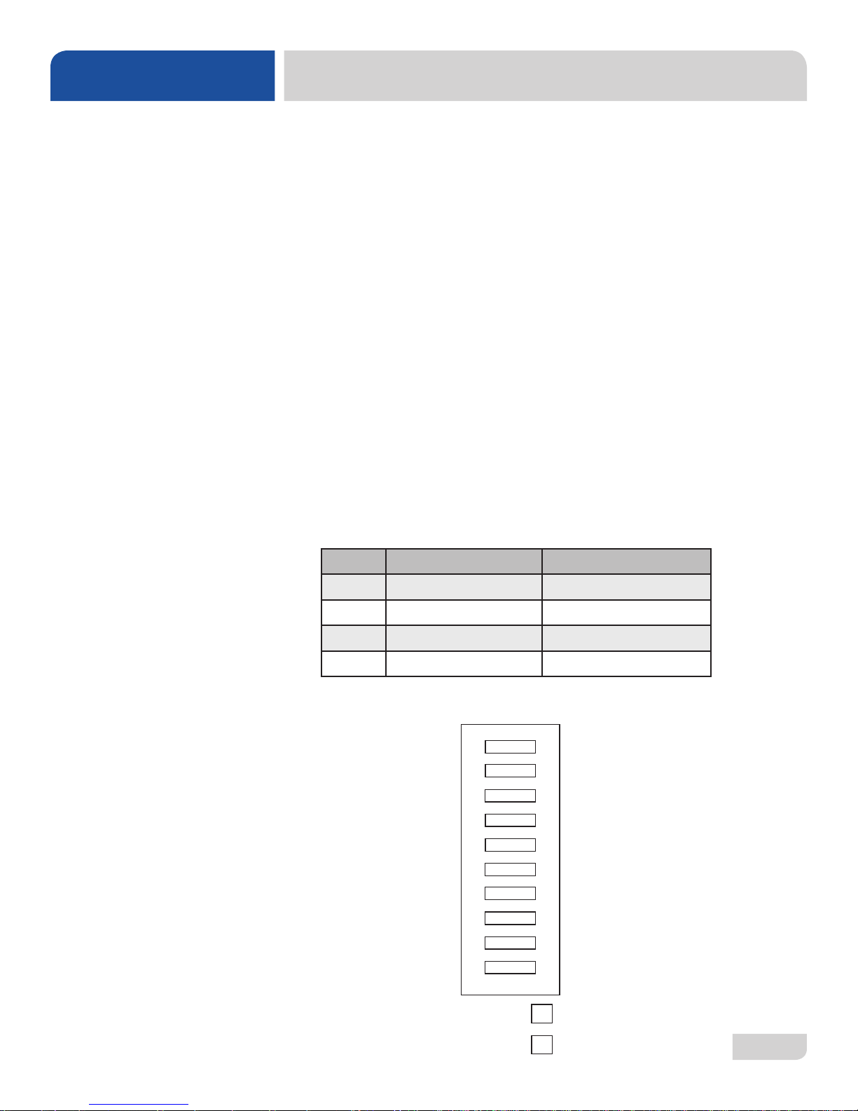
To access the programming mode, the machine must be ON and idle (between
cycles).
On the timer board, press and hold both the MOVE and ENTER buttons on the timer
board simultaneously for two seconds.
The PROGRAM (PGM) light and light A will illuminate.
NOTE: Once in the programming mode, the MOVE button is used to scroll between
the programming categories and the ENTER button is used to select the category.
Press the MOVE button to move the solid light to the desired location of FILL, RINSE
AID, DETERGENT, or SANITIZER. Please note that options A, B, C, and D are not
adjustable outputs.
Press the ENTER button for the chosen category. Now, the (PGM) light will illuminate
along with lights corresponding to the time values for the chosen category. The
ACCEPT light will blink.
The PROGRAM light will illuminate.
07610-004-37-13-E
9
Page 17
INSTALLATION
INSTRUCTIONS
PROGRAMMING
CHEMICAL
FEEDER PUMPS
To change the value of a parameter, use the MOVE button to illuminate the light next
to the time option (time is measured in seconds). In the time categories, each second
in use will light up. To deselect the option, press ENTER and the light will go off, press
ENTER again and it will illuminate. Once you have set your time category, press the
MOVE button until the ACCEPT light illuminates and press ENTER. This will save the
changed parameters and exit the programming mode.
To change any other values, you will have to return to the programming mode. To
revert back to a previous setting, you must return to that option and change the
parameter back to the previous setting.
Once in the programming mode, if there have been no keypad inputs for approximately
two minutes, the system will automatically exit out of the programming mode. Any
changes to parameters will be lost when the programming mode is automatically
exited.
The wash and drain cycles are not adjustable.
All time adjustments are in seconds. Refer to the chart below for adjustable outputs.
PGM DishStar® HT DishStar® LT/LT-H
E Not adjustable Rinse-Aid
F Rinse Fill
G Detergent Sanitizer
H Rinse-Aid Detergent
TIMER PROGRAMMING BOARD
PGM
A
B
C
D
E
F
G
H
ACCEPT
TIME IN SECONDS
8
4
2
1
0.8
0.4
0.2
0.1
07610-004-37-13-E
MOVE
ENTER
10
Page 18
INSTALLATION
INSTRUCTIONS
LEVELING
HEATER CONT ACTOR
WIRES (HT ONLY)
!
CAUTION
Heater contactor wires
must NOT be connected
before water lls the unit
the rst time!
The dishmachine is designed to operate while level. This is important to prevent any
damage to the machine during operation and to ensure the best possible results. The
unit comes equipped with adjustable bullet feet which can be turned using a pair of
pliers. Since this machine is an undercounter unit, it should be levelled as close as
possible to the unit's location before it is pushed under the counter.
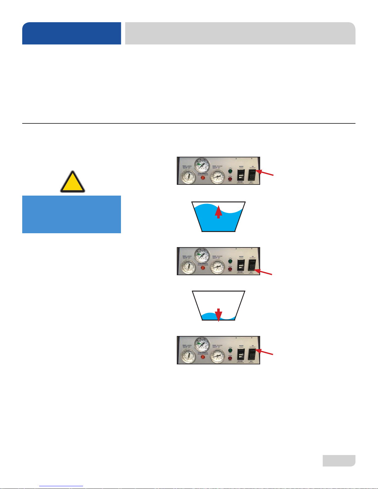
1. Flip the "ON/OFF" switch to "ON."
2. Listen for the water to stop lling.
3. Flip the "ON/OFF" switch to "OFF."
07610-004-37-13-E
4. Listen for the water to stop draining.
5. Flip the "ON/OFF" switch back to "ON."
6. Listen for the water to stop lling.
7. Flip the "ON/OFF" switch back to "OFF."
8. Listen for the water to stop draining.
9. Flip the "ON/OFF" switch back to "ON."
10. Listen for the water to stop lling. This time the water should begin to splash
into the cavity of the machine.
11. Once you hear water splashing, ip the "ON/OFF" switch back to "OFF."
12. Listen for the water to stop draining.
11
Page 19

INSTALLATION
INSTRUCTIONS
HEATER CONT ACTOR
WIRES (HT ONLY)
Disconnect electrical
power at the breaker or
disconnect switch and
tag-out in accordance with
procedures and codes.
13. Disconnect electrical power at the breaker or disconnect switch and tag-out in
accordance with procedures and codes.
14. Remove the front panel of the machine.
15. Locate the disconnected orange/white wires.
16. Connect the wires by pushing the connectors rmly together.
17. Replace the front panel of the machine.
18. Reconnect electrical power at the breaker or disconnect switch in accordance
with procedures and codes.
19. The machine is now ready for operation.
07610-004-37-13-E
12
Page 20

OPERATION
OPERATING INSTRUCTIONS
PREPARATION
Before operating the unit, verify the following:
1. Strainer is in place and clean.
2. Wash and rinse arms are screwed securely into place and end-caps are tight.
3. Wash and rinse arms rotate freely.
07610-004-37-13-E
FILLING THE
WASH TUB
4. Chemical levels in chemical containers are correct.
1. Close the door.
2. Flip the “ON/OFF” switch to the “ON” position.
(HT Controls Shown.)
3. The unit will automatically begin to fill.
4. Once the wash tub is filled, wait for five minutes.
5. Flip the “ON/OFF” switch to the “OFF” position and wait for unit to drain.
6. Flip the “ON/OFF” switch to the “ON” position and wait for unit to fill.
7. Ensure wash temperature is at least 150 °F before operating the unit.
13
Page 21
OPERATION
OPERATING INSTRUCTIONS
WARE
PREPARATION
W ASHING A RACK
OF WARE
OPERATIONAL
INSPECTION
Proper preparation of ware will help ensure good results and fewer re-washes. If not
done properly, ware might not come out clean and the efciency of the dishmachine
will be reduced. Putting unscraped dishes into the machine affects its performance,
so scraps should always be removed from ware before being loaded into a rack.
Pre-rinsing and pre-soaking are good ideas, especially for silverware and casserole
dishes.
Place cups and glasses upside-down in racks so they don't hold water during the
cycle. The dishmachine sanitizes as well as cleans. To do this, ware must be properly
prepared before being placed in the machine.
To wash a rack, open the door completely and slide the rack into the unit. Close the
door, ensure the "W ASH/DELIME" switch is on "WASH," press the "Start" button, and
the unit will start. After the cycle light turns off, the cycle is complete. When the ush
light is on (steady, not ashing), tank water should be drained and relled.
Based on use, the strainer might become clogged with soil and debris as the
workday progresses. Operators should regularly inspect the strainer to ensure it has
not become clogged. If clogged, it will reduce the washing capability of the machine.
Instruct operators to clean out the strainer at regular intervals or as required by
workload.
07610-004-37-13-E
SHUTDOWN &
CLEANING
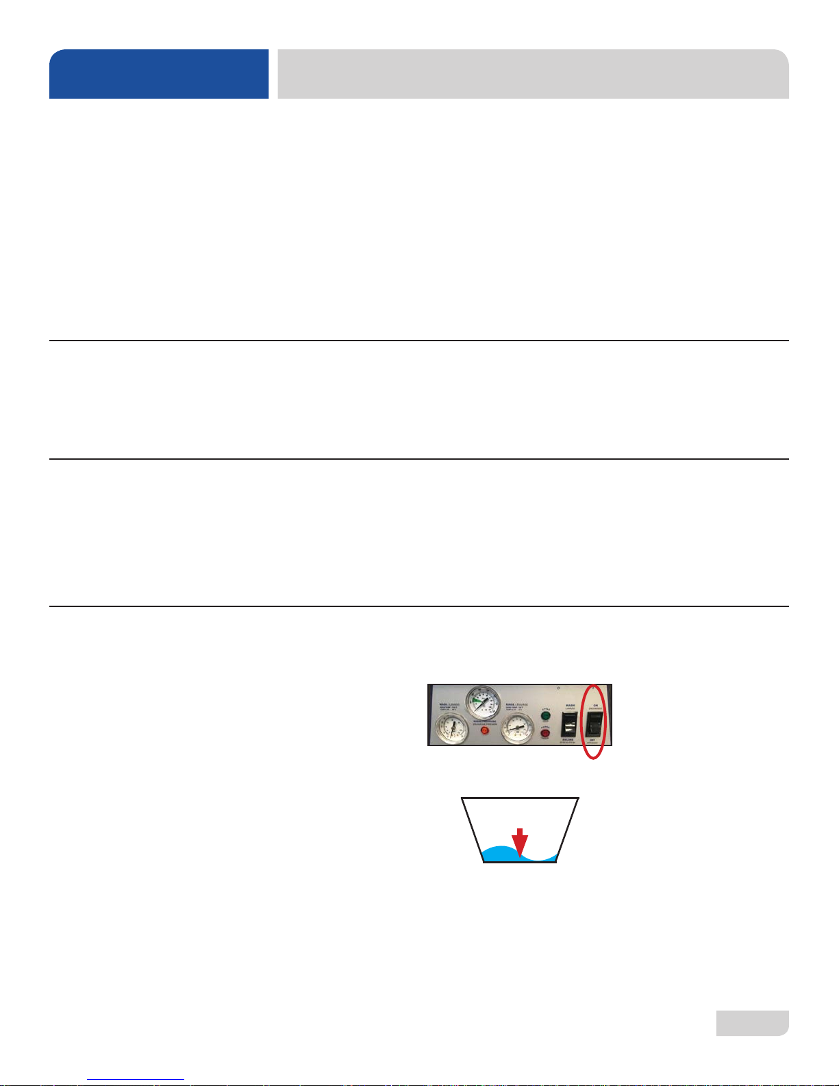
1. At the end of the workday, close the door. Flip the “ON/OFF” switch to the “OFF”
position.
(HT Controls Shown.)
2. The drain pump will activate and empty the unit of water.
14
Page 22
OPERATION
OPERATING INSTRUCTIONS
SHUTDOWN &
CLEANING
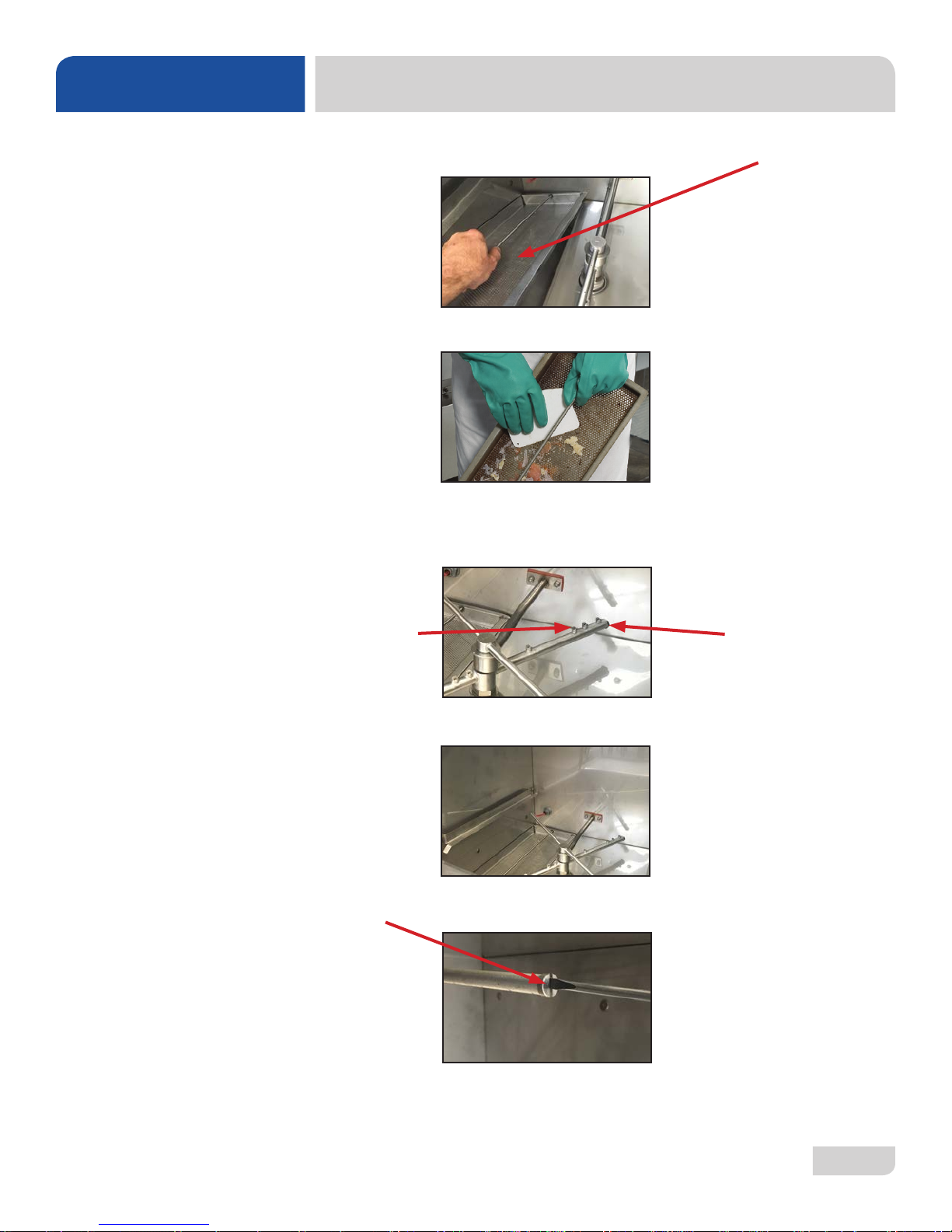
3. When draining stops, remove the strainer.
4. Remove soil and debris from the strainer and set to the side.
5. Unscrew the wash and rinse arms from their manifolds. Remove the end-caps and
ush the arms with water. Use a brush to clean out the inside of the arms. If the
nozzles appear to be clogged, use a toothpick to remove the obstruction.
Nozzle
6. Wipe the inside of the unit out, removing all soil and scraps.
7. Reassemble the wash/rinse arms.
End-Cap
07610-004-37-13-E
15
Page 23
OPERATION
OPERATING INSTRUCTIONS
SHUTDOWN &
CLEANING
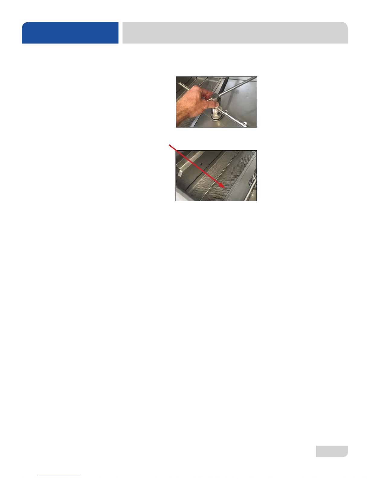
8. Replace the wash and rinse arms in the unit. The arms only need to be hand-tight; do
not use tools to tighten them down.
9. Reinstall the strainer and close the door.
07610-004-37-13-E
16
Page 24
OPERATION
NOTICE
OPERATING INSTRUCTIONS
DELIMING
NOTE: If this machine is
equipped with an
HTS-11 scale prevention
and corrosion control
device and lime is
becoming a frequent
problem, the cartridge
needs to be replaced.
To order a replacement
cartridge, call the
manufacturer.
To proceed with the delime operation, follow the steps below. The tank capacities of
the machine can be found in the Specications section of this manual.
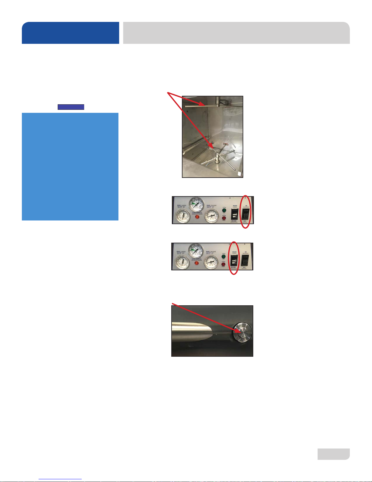
1. Remove rinse arms and place in sink with deliming solution (HT only).
2. Flip the "ON/OFF" switch to the "ON" position.
3. Flip the "WASH/DELIME" switch to the "DELIME" position.
4. Add deliming solution per chemical supplier's instructions.
5. Close the door.
6. Push the "START" button.
7. Wait until cycle is complete and inspect the inside of the machine. If the
machine is not delimed, run again.
This equipment is not recommended for use with deionized water or other aggressive
uids. Use of deionized water or other aggressive uids will result in corrosion and
failure of materials and components. Use of deionized water or other aggressive uids
will void the manufacturer’s warranty.
07610-004-37-13-E
17
Page 25

OPERATION
OPERATING INSTRUCTIONS
DETERGENT
CONTROL
Detergent usage and water hardness are two factors that contribute greatly to how
efciently this dishmachine will operate. Using detergent in the proper amount can
become a source of substantial savings. A qualied water treatment specialist can
determine what is needed for maximum efciency from the detergent.
1. Hard water greatly affects the performance of the dishmachine, causing the
amount of detergent required for washing to increase. If the machine is installed
in an area with hard water, the manufacturer recommends the installation of
water treatment equipment.
2. Deposited solids from hard water can cause spotting that will not be removed
with a drying agent. Treated water will reduce this occurence.
3. Treated water may not be suitable for use in other areas of operation and it
may be necessary to install a water treatment unit for the water going to the
dishmachine only. Discuss this option with a qualied water treatment specialist.
4. Dishmachine operators should be properly trained on how much detergent is to
be used per cycle. Meet with a water treatment specialist and detergent vendor
to discuss a complete training program for operators.
5. This dishmachine requires that chemicals be provided for proper operation and
sanitization. Contact a chemical supplier with any questions.
6. Water temperature is an important factor in ensuring that the dishmachine
functions properly, and the machine's data plate details what the minimum
i
temperatures must be for the incoming water supply, the wash tank, and the
rinse tank. If minimum requirements are not met, there is a possibility that dishes
will not be clean or sanitized.
7. Instruct dishmachine operators to observe the required temperatures and to
report when they fall below the minimum allowed. A loss of temperature can
indicate a larger problem.
07610-004-37-13-E
18
Page 26

MAINTENANCE
PREVENTATIVE MAINTENANCE
PREVENTATIVE
MAINTENANCE
The manufacturer highly recommends that any maintenance and repairs not specically
discussed in this manual be performed only by QUALIFIED SERVICE PERSONNEL.
Performing maintenance on your dishmachine may void your warranty, lead to larger
problems, or even cause harm to the operator. So if you have a question or concern, do
not hesitate to contact a QUALIFIED SERVICE AGENCY.
By following the operating and cleaning instructions in this manual, you should get the
most efcient results from your machine. As a reminder, here are some steps to take to
ensure that you are using the dishmachine the way it was designed to work:
1. Ensure that the water temperatures match those listed on the machine data plate.
There can be a variety of reasons why your water temperature could be too low.
2. Ensure that all strainers are clean and securely in place before operating the machine.
When cleaning out strainers, do NOT beat them on waste cans. Wipe out strainers
with a rag and rinse under a faucet if necessary. Use a toothpick to dislodge any
stubborn debris.
3. Ensure that all wash and rinse arms are secure in the machine before operating.
4. Remove as much soil from dishes by hand as possible before loading into racks.
5. Do not overll racks.
6. Ensure that glasses are placed upside-down in the rack.
7. Ensure that all chemicals being injected into machine have been veried at the correct
concentrations.
8. Clean out the machine at the end of every workday per the Shutdown and Cleaning
section of this manual.
9. Follow all safety procedures, whether listed in this manual or put forth by local, state,
or national codes/regulations.
07610-004-37-13-E
19
Page 27
TROUBLESHOOTING
WARNING: Inspection, testing, and repair of electrical equipment should only be performed by qualied
!
WARNING
PROBLEM POSSIBLE CAUSE REMEDY
Water overow
from bottom of
door.
service personnel. Certain procedures in this section require electrical tests or measurements while
power is applied to the machine. Exercise extreme caution at all times. If test points are not easily
accessible, disconnect power, attach test equipment, and reapply power to test. When replacing
electrical parts, disconnect power at source circuit breaker.
1. Clogged drain.
2. Machine not level.
1. Remove obstruction.
2. Level machine or increase height to the front.
COMMON PROBLEMS
Wash motor
doesn’t
operate on
delime wash.
No water
comes through
the arms when
the "WASH/
DELIME" switch
is depressed.
3. Excessive inlet pressure.
4. Detergent foaming.
5. Wash/rinse arm end-cap missing.
1. Loose or broken wires.
2. Defective "WASH/DELIME" switch.
3. Defective motor starting relay .
4. Machine in FAULT mode and locked out.
1. Water not turned on.
2. Defective solenoid valve
3. Install pressure regulator or adjust if one is present.
Ensure ow meets data plate specication.
4. Reduce detergent quantity.
5. Replace.
1. Reconnect or replace wires in motor.
2. Verify "WASH/DELIME" switch triggers input on PLC. If
not, check wiring/replace membrane.
3. Replace.
4. Review fault screen for active faults.
1. Turn water on.
2. Replace solenoid valve.
Little or no water
coming through
the wash/rinse
assemblies.
Rinse water runs
continuously
with breaker
turned off.
07610-004-37-13-E
1. Limed-up heads or piping.
2. Low water pressure.
1. Defective plunger in solenoid valve.
2. Defective diaphragm in solenoid valve.
1. Delime heads.
2. Adjust pressure regulator (not supplied) or increase
pipe size to machine.
1. Replace.
2. Replace diaphragm.
20
Page 28

TROUBLESHOOTING
PROBLEM POSSIBLE CAUSE REMEDY
Wash
temperature
not at required
temperature
range.
1. Water level low.
2. RTD setpoint too slow.
3. Defective RTD.
1. Check water level. If low, run new ll cycle.
2. Check fault screen. Adjust wash temperature setpoint
3. Replace.
COMMON PROBLEMS
Rinse water
not at
required
temperature
range.
Machine
doesn’t drain
when power
button is
pressed.
No indication of
pressure.
4. Wash heater defective.
5. Defective heater contactor R1.
1. Incoming rinse water does not
meet minimum criteria indicated on
machine data plate.
2. RTD is defective.
3. Rinse heaters damaged.
4. Setpoint screens set low.
1. Drain clogged.
2. Defective drain valve.
1. Water turned off.
2. Pressure gauge failure.
4. Replace heater element.
5. Replace.
1. Adjust as required.
2. Replace if necessary.
3. Check amperages. Replace if necessary.
4. Adjust rinse tank setpoint.
1. Remove obstruction.
2. Replace.
1. Turn water on.
2. Replace pressure gauge.
07610-004-37-13-E
21
Page 29
PARTS
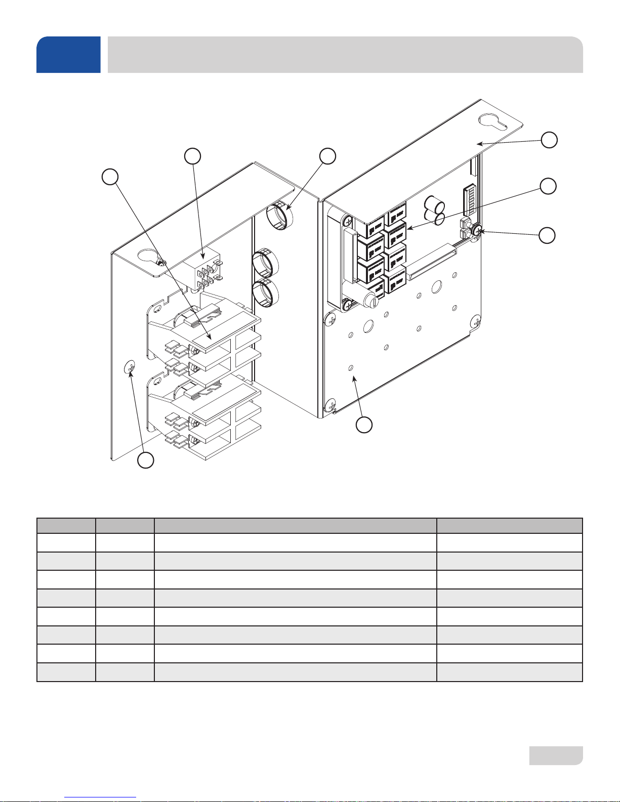
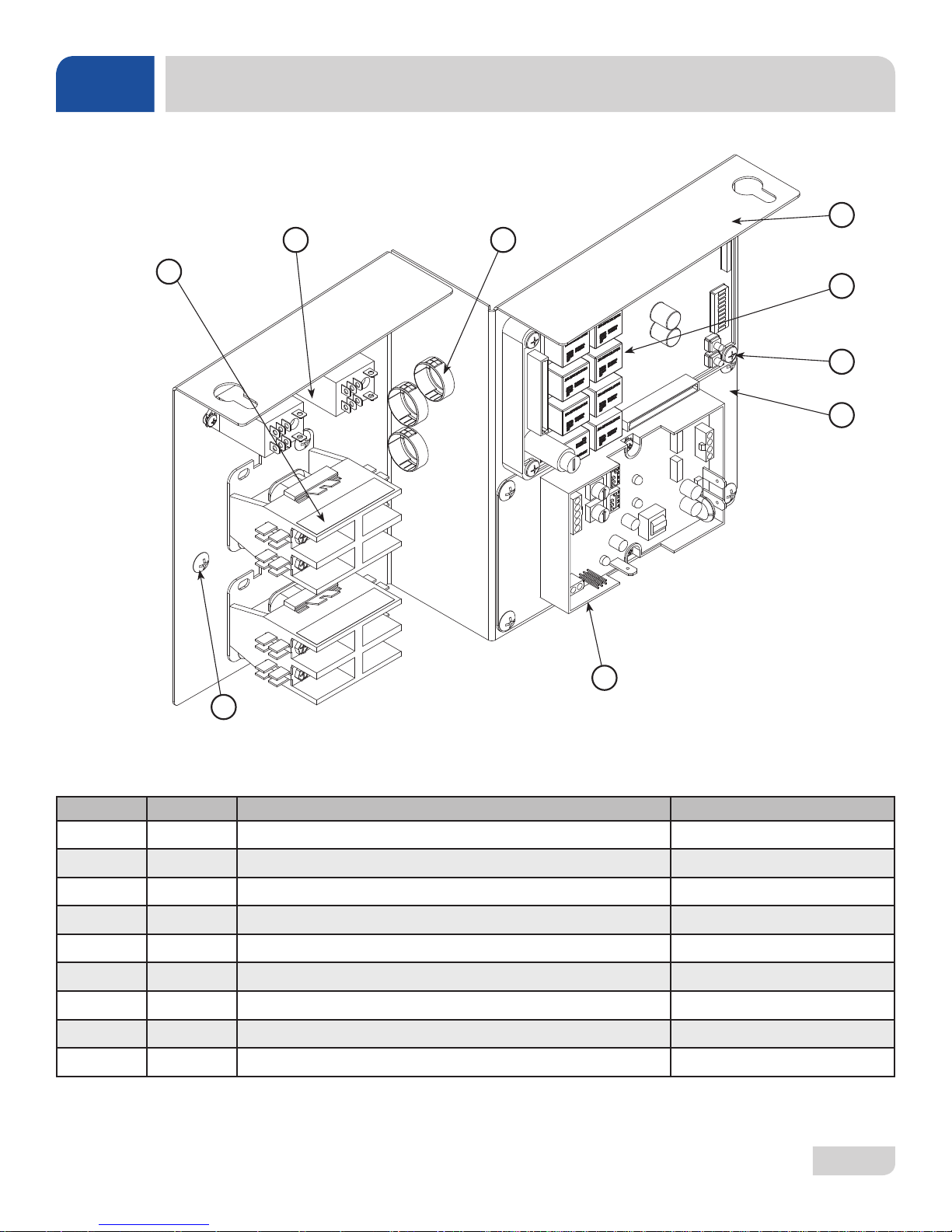
HT CONTROL PANEL
4
2 3
1
7*
8
5
6
ITEM QTY DESCRIPTION PART NUMBER
1 2 Contactor, 30 A, 240 V 05945-002-74-20
2 1 Relay, Omron 05945-111-89-75
3 3 Open/Closed Bushing 05975-003-35-21
4 1 Control Panel Weldment 05700-004-35-76
5 1 Universal Timer 05945-003-75-23
6 4 Screw, 10-32 x 1" 05305-002-19-42
7* 1 Peri-pump Plate 05700-004-35-78
8 9 Screw, 10-32 x 3/8" 05305-173-12-00
*See Chemical Feeder Pump Assembly page for Peri-pumps.
07610-004-37-13-E
22
Page 30
PARTS
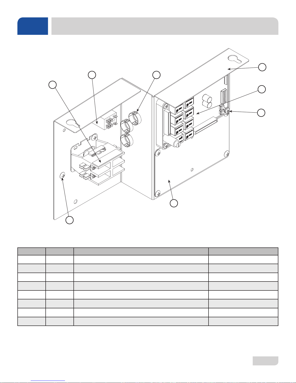
LT CONTROL PANEL
4
2 3
1
7
8
5
6
ITEM QTY DESCRIPTION PART NUMBER
1 1 Contactor, 110 V 05945-109-05-69
2 1 Relay, Omron 05945-002-47-41
3 3 Open/Closed Bushing 05975-003-35-21
4 1 Control Panel Weldment 05700-004-35-76
5 1 Universal Timer 05945-003-75-23
6 4 Screw, 10-32 x 1" 05305-002-19-42
7 1 Thermostat Plate 05700-004-37-67
8 7 Screw, 10-32 x 3/8" 05305-173-12-00
07610-004-37-13-E
23
Page 31
PARTS
LT-H CONTROL PANEL
4
2 3
1
8
9
5
6
7
ITEM QTY DESCRIPTION PART NUMBER
1 2 Contactor, 110 V 05945-109-05-69
2 2 Relay, Omron 05945-002-47-41
3 3 Open/Closed Bushing 05975-003-35-21
4 1 Control Panel Weldment 05700-004-35-76
5 1 Universal Timer 05945-003-75-23
6 4 Screw, 10-32 x 1" 05305-002-19-42
7 1 Thermostat Plate 05700-004-37-67
8 1 Thermostat, ELAN Electric (Dual) 06685-004-17-27
9 7 Screw, 10-32 x 3/8" 05305-173-12-00
07610-004-37-13-E
24
Page 32
PARTS
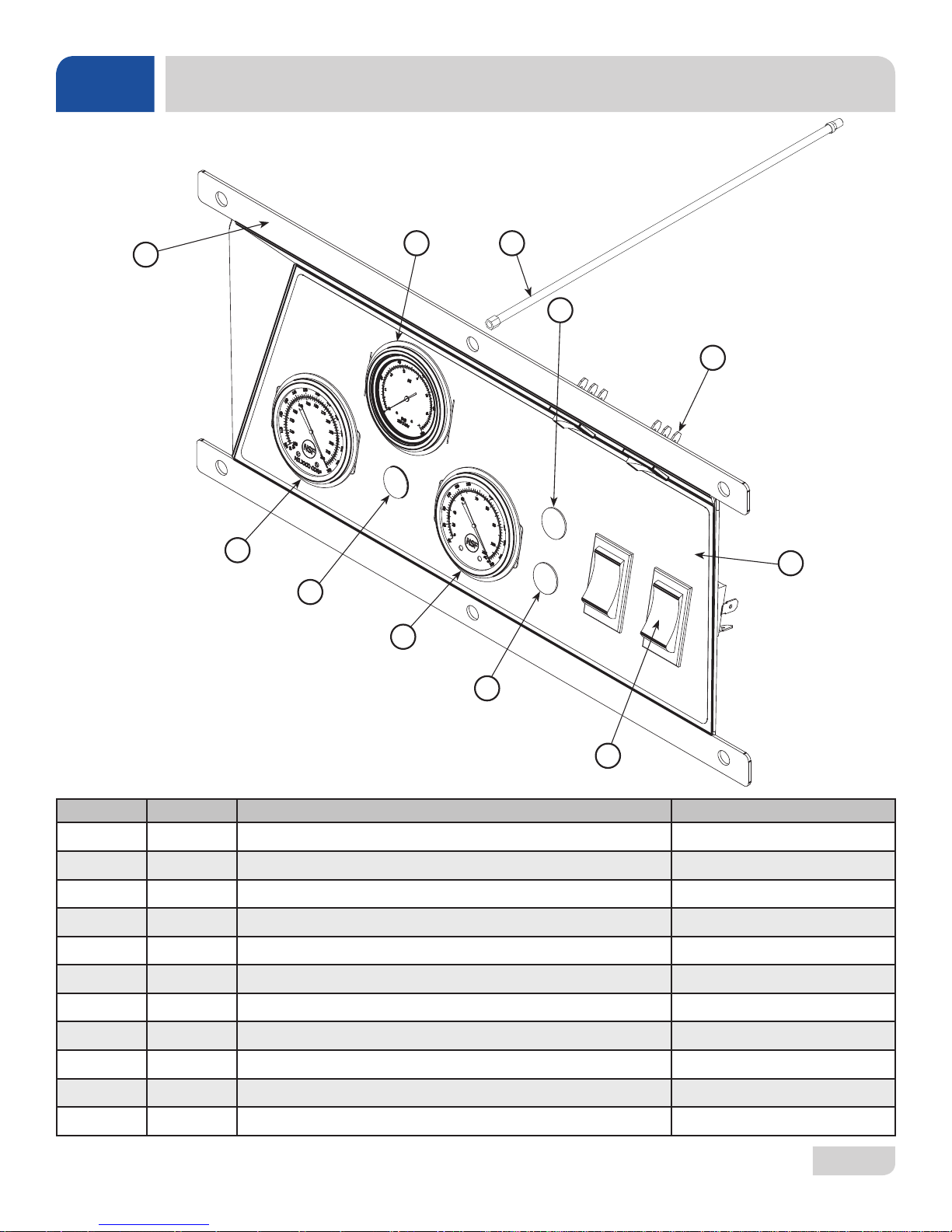
HT DISPLAY PANEL
1
11
10
2
9
3
4
5
6
8
7
ITEM QTY DESCRIPTION PART NUMBER
1 1 Bracket, Control Panel 05700-004-35-82
2 1 Gauge, with Green Zone 06680-011-86-42
3 1 Hose, Pressure Gauge 05700-004-36-95
4 1 Light, Green 05945-111-44-43
5 2 Prime Switch 05930-011-49-54
6 1 Decal, Display Panel 09905-004-35-39
7 2 Switch 05930-011-49-55
8 1 Light, Red 05945-111-44-45
9 1 Rinse Gauge, 96" 06685-004-31-46
10 1 Light, Amber 05945-111-44-44
11 1 Wash Gauge, 48" 06685-004-31-47
07610-004-37-13-E
25
Page 33
PARTS
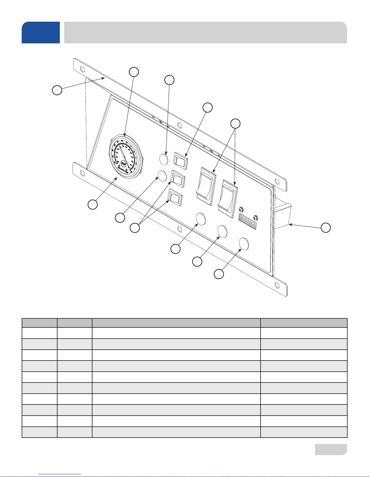
LT DISPLAY PANEL
2
3
1
4
5
10
3
4
9
8
7
ITEM QTY DESCRIPTION PART NUMBER
1 1 Bracket, Control Panel 05700-004-37-73
2 1 Thermometer, 48" Rinse 06685-004-31-47
3 2 Light, Red 05945-504-07-18
4 3 Prime Switch 05930-011-49-54
5 2 Switch 05930-011-49-55
6 1 Counter 05990-111-35-38
6
7 1 Light, Amber 05945-111-44-44
8 1 Light, Green 05945-111-44-43
9 1 Light, Red 05945-111-44-45
10 1 Decal, Display Panel 09905-004-37-72
07610-004-37-13-E
26
Page 34
PARTS
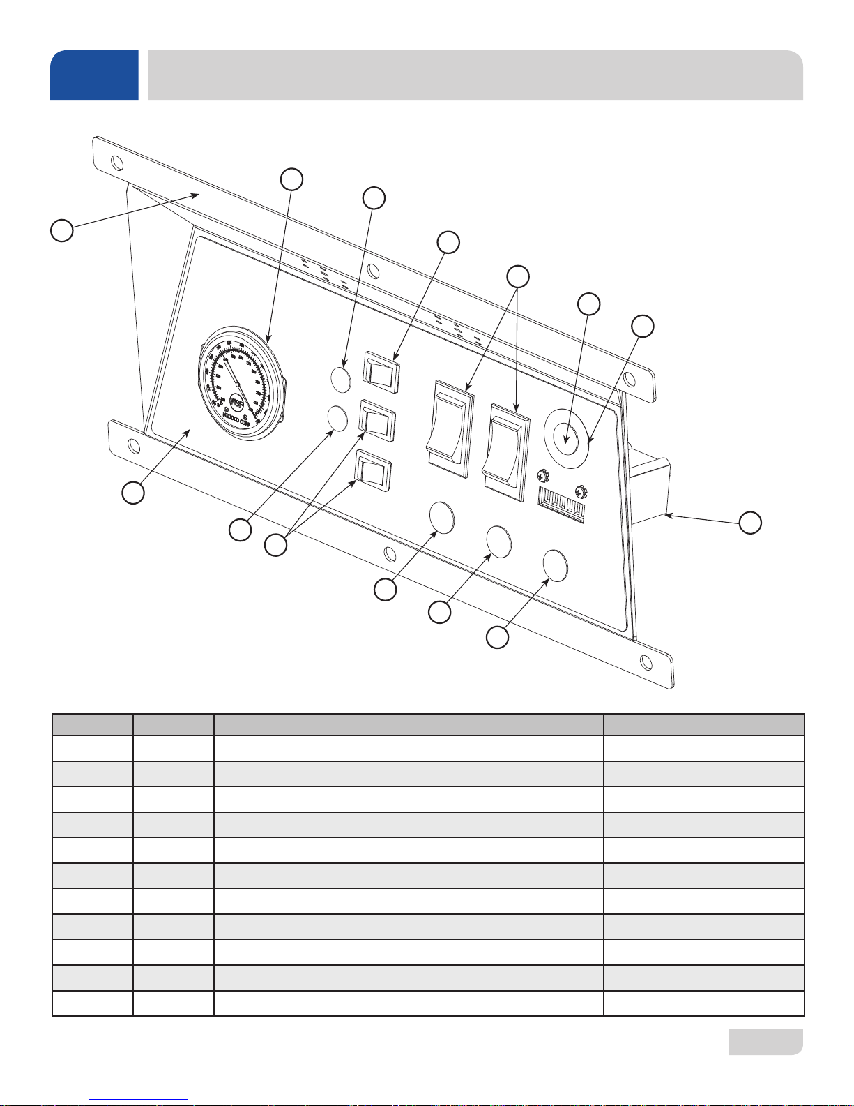
LT-H DISPLAY PANEL
2
3
1
11
3
4
6
4
5
6
7
8
10
9
ITEM QTY DESCRIPTION PART NUMBER
1 1 Bracket, Control Panel 05700-004-37-73
2 1 Thermometer, 48" Rinse 06685-004-31-47
3 2 Light, Red 05945-504-07-18
4 3 Prime Switch 05930-011-49-54
5 2 Switch 05930-011-49-55
6 2 Light, Red 05945-111-44-45
7 1 Decal, Hi-Limit Ring 09905-004-37-89
8 1 Counter 05990-111-35-38
9 1 Light, Amber 05945-111-44-44
10 1 Light, Green 05945-111-44-43
11 1 Decal, Display Panel 09905-004-37-72
07610-004-37-13-E
27
Page 35
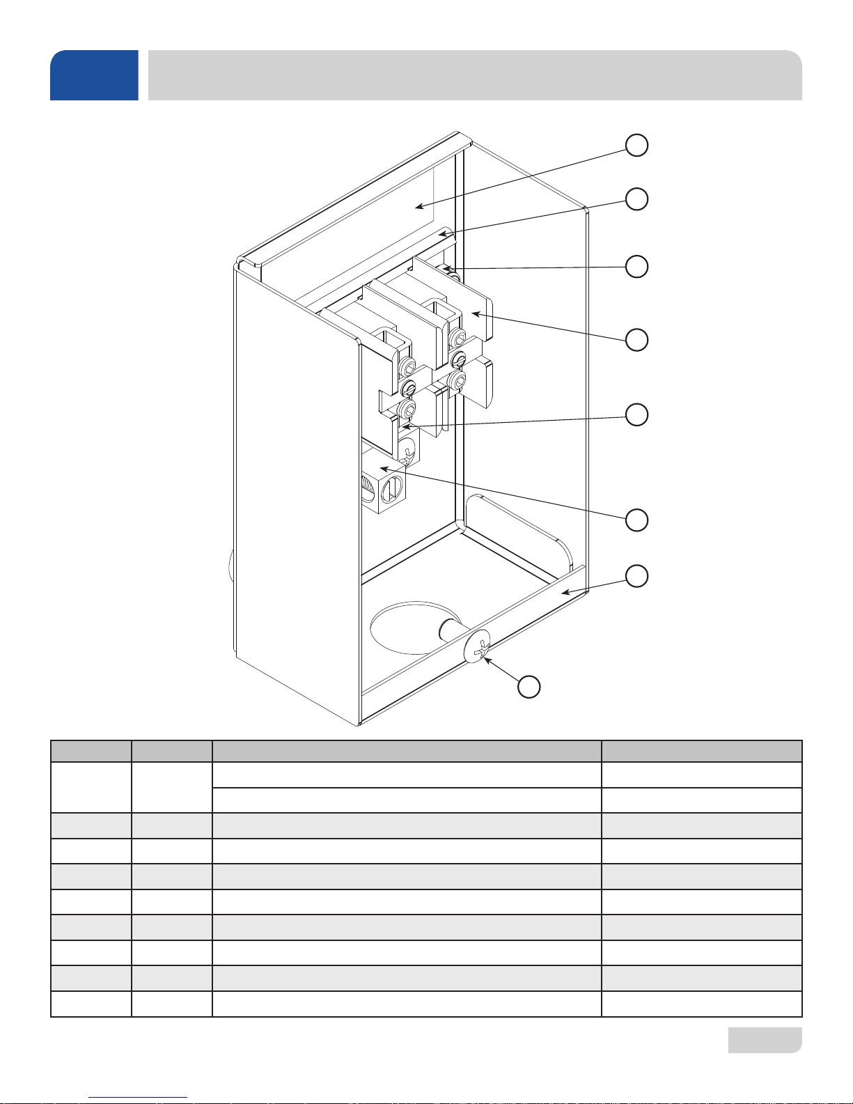
PARTS
TERMINAL BLOCK BOX ASSEMBLY
3
8
7
6
1
5
2
4
ITEM QTY DESCRIPTION PART NUMBER
1 1
2 1 Terminal Block Box 05700-003-27-69
1 Terminal Box Cover (Not Shown) 05700-003-27-70
3 1 Decal, Copper Conductors 09905-011-62-72
4 2 Screw, 10-32 x 1/2" 05305-011-39-36
Decal, Power Connections, HT 09905-011-47-35
Decal, Power Connections, LT/LT-H 09905-011-47-64
5 1 Ground Lug 05940-200-76-00
6 2 Terminal Block 05940-500-02-19
7 1 Locknut, 10-24 SS Hex with Nylon Insert 05310-373-01-00
8 1 Terminal Block Track 05700-000-43-60
07610-004-37-13-E
28
Page 36
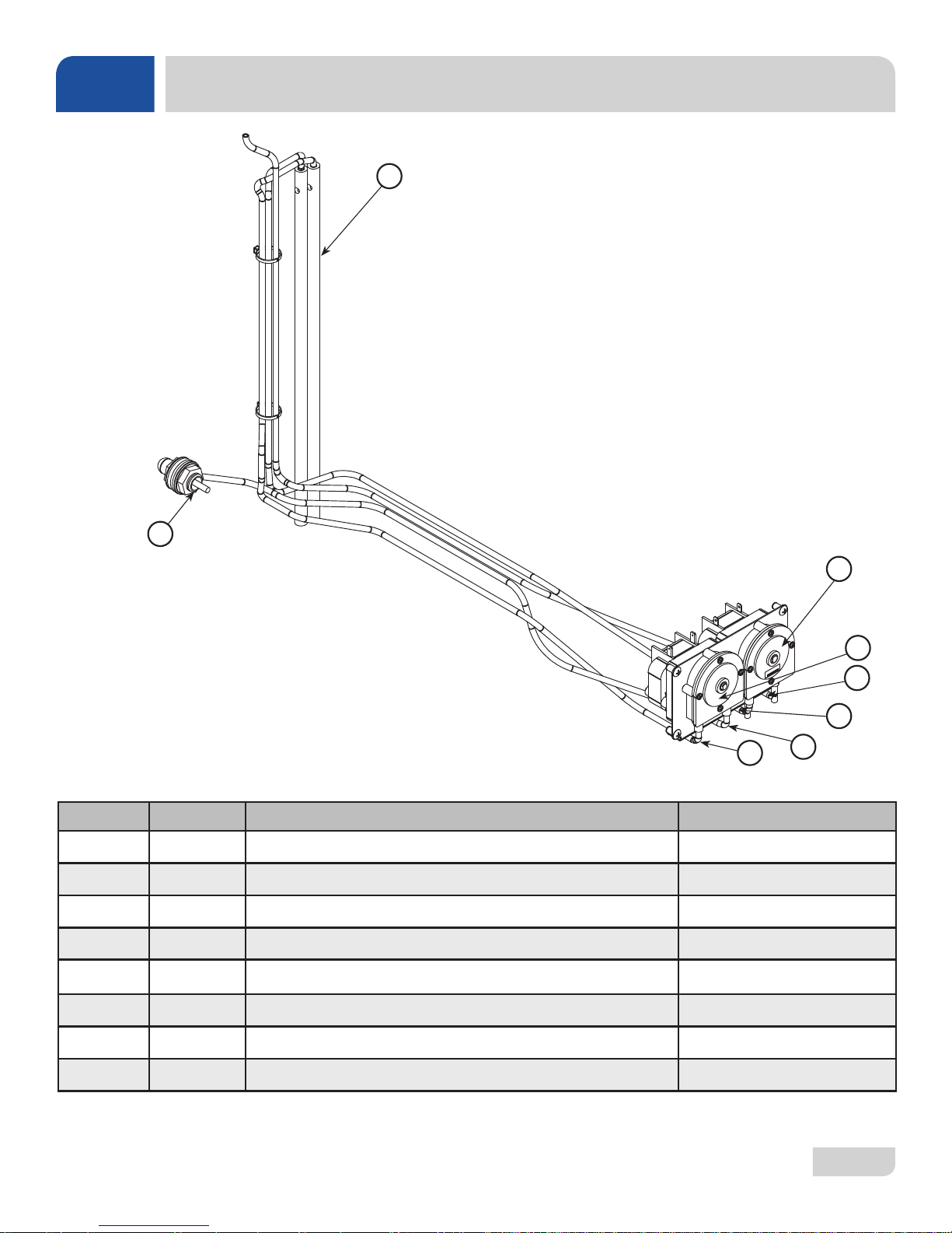
PARTS
HT CHEMICAL FEEDER PUMP ASSEMBLY
1
8
7
6
ITEM QTY DESCRIPTION PART NUMBER
1 2 Stiffener , Chemical T ube 05700-002-66-49
2 1 Peri-pump, 14 RPM 05700-002-72-48
3 1 Peri-pump, 36 RPM 05700-003-78-74
4 1 Chemical Tube 05700-011-37-12
5 1 Chemical Tube 05700-011-37-13
6 1 Chemical Tube 05700-011-37-14
2
3
4
5
7 1 Chemical Tube 05700-011-37-15
8 1 Bulkhead to 1/2" Hose Barb Assembly 05700-004-30-86
07610-004-37-13-E
29
Page 37
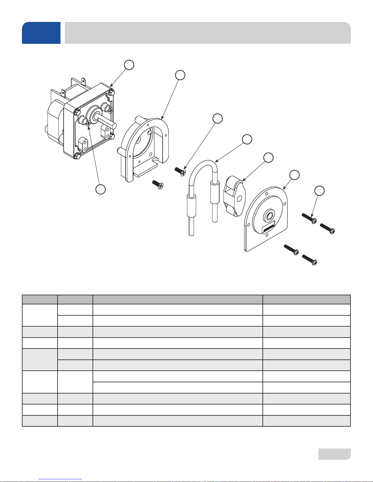
PARTS
HT CHEMICAL FEEDER PUMP COMPONENTS
1
2
3
4
5
6
8
ITEM QTY DESCRIPTION PART NUMBER
1 Motor, 14 RPM 240 V Rinse Aid Feeder Pump 04320-111-47-46
1
1 Motor, 36 RPM 240 V Detergent Feeder Pump 04320-111-47-47
2 1 Rear Housing 04320-111-37-09
3 2 Screw, 8-32 x 1/2" Phillips Pan Head 05305-011-37-06
1 Squeeze Tube (goes with 14 RPM) 05700-011-65-21
4
1 Squeeze Tube (goes with 36 RPM) 05700-003-22-89
7
5 1
Roller, Black (goes with 14 RPM) 04320-111-65-27
Roller, White (goes with 36 RPM) 04320-002-82-28
6 1 Front Housing 04320-111-37-08
7 4 Screw, 6-32 x 3/4" Phillips Pan Head 05700-011-37-05
8 2 Screw, 8-32 x 3/8" Phillips Pan Head 04320-111-37-07
07610-004-37-13-E
30
Page 38
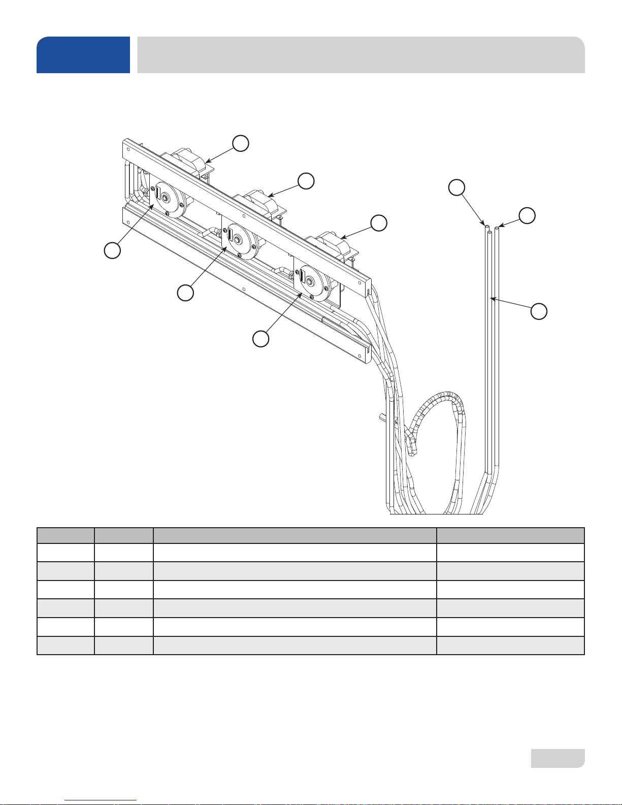
PARTS
LT/LT-H CHEMICAL FEEDER PUMP ASSEMBLY
1
2
2
6
6
6
3
4
5
ITEM QTY DESCRIPTION PART NUMBER
1 1 Motor, 14 RPM 04320-111-35-13
2 2 Motor, 36 RPM 04320-111-35-14
3 1 Tubing, White 05700-002-62-13
4 1 Tubing, Blue 05700-002-62-11
5 1 Tubing, Red 05700-002-62-12
6 3 Pump Cover 04320-111-37-08
07610-004-37-13-E
31
Page 39
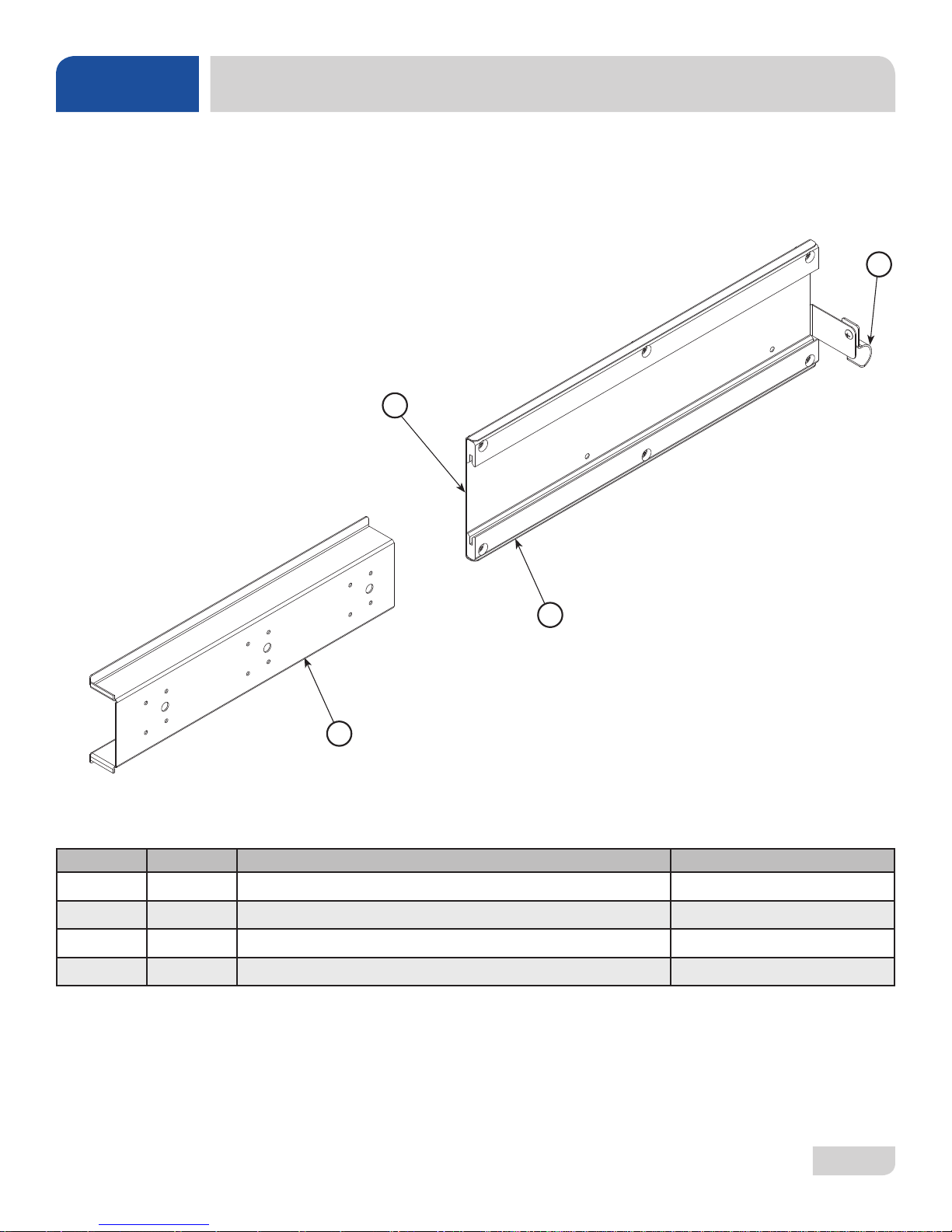
PARTS
LT/LT-H PERI-PUMP TRACK ASSEMBLY
2
1
3
4
ITEM QTY DESCRIPTION PART NUMBER
1 1 Track Mount 05700-004-37-93
2 1 Pipe Clamp 05700-000-35-05
3 2 Peri-pump Track 05700-003-33-29
4 1 Peri-pump Plate 05700-003-54-41
07610-004-37-13-E
32
Page 40
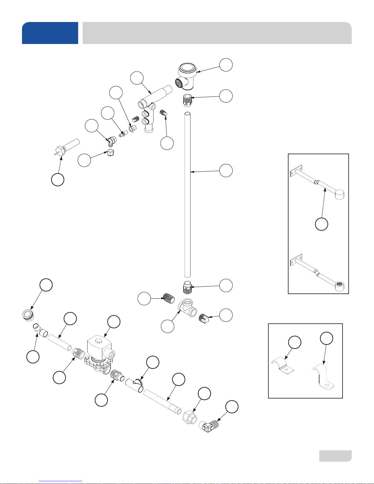
PARTS
HT PLUMBING ASSEMBLIES
6
9
25
12
11
10
13
4
7
5
23
15
16
07610-004-37-13-E
4
3
17
4
22
14
1
20
21
18
2
24
19
8
33
Page 41
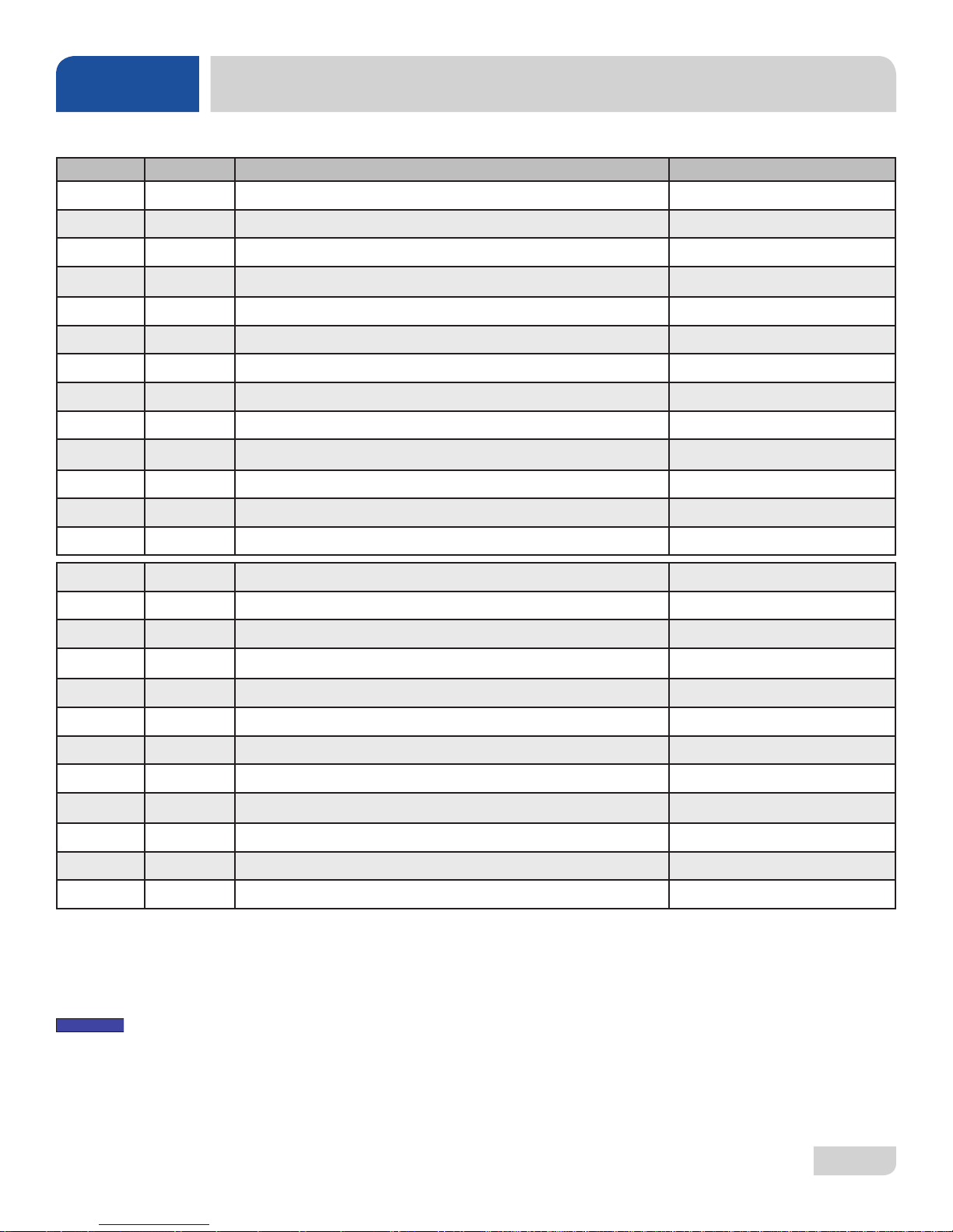
NOTICE
PARTS
ITEM QTY DESCRIPTION PART NUMBER
1 1 Tee, 1/2" Brass 04730-211-27-00
2 1 Plug, 1/2" Brass Pipe 04730-209-03-00
3 1 Nipple, 1/2" Close Brass 04730-207-15-00
4 3 Adapter, Male 04730-401-03-01
5 1 Tube, Copper 1/2" x 22" 05700-003-32-16
6 1 Vacuum Breaker 04820-003-06-13
7 2 Plug, 1/4" Brass 04730-209-01-00
8 1 Pipe Clamp 05700-011-38-62
9 1 Injector Adapter 05700-031-40-44
10 1 Check Valve 04820-111-51-14
11 1 Fitting, Outlet Elbow 04820-111-51-18
12 1 Nut, Tube 04730-011-59-45
HT PLUMBING ASSEMBLIES
13 1 Bushing, 1/4" x 1/8" 04730-003-05-61
14 1 Valve, 1/2" 208/60 04810-003-71-56
15 1 Hose Adapter 04720-004-24-68
16 1 Elbow, 1/2" 04730-406-31-01
17 1 Copper Tube 1/2" x 3" 05700-003-36-25
18 1 Union, 1/2" 04730-412-05-01
19 1 Elbow, 1/2" 90-Degree 04730-406-32-01
20 1 Tee, 1/2" x 1/2" x 1/4" Female 04730-411-25-01
21 1 Copper Pipe, 4 3/4" Long 05700-002-91-02
22 1 Adapter, 1/2" Male 04730-011-59-53
23 2 Rinse Hub Weldment 05700-021-38-31
24 2 Pipe Clamp (Side of Unit) 05700-000-35-05
25 1 Thermometer,100-220 Degrees 48" SS 06685-004-31-47
NOTE: Use teon tape on threads. Do NOT use "pipe dope."
07610-004-37-13-E
34
Page 42
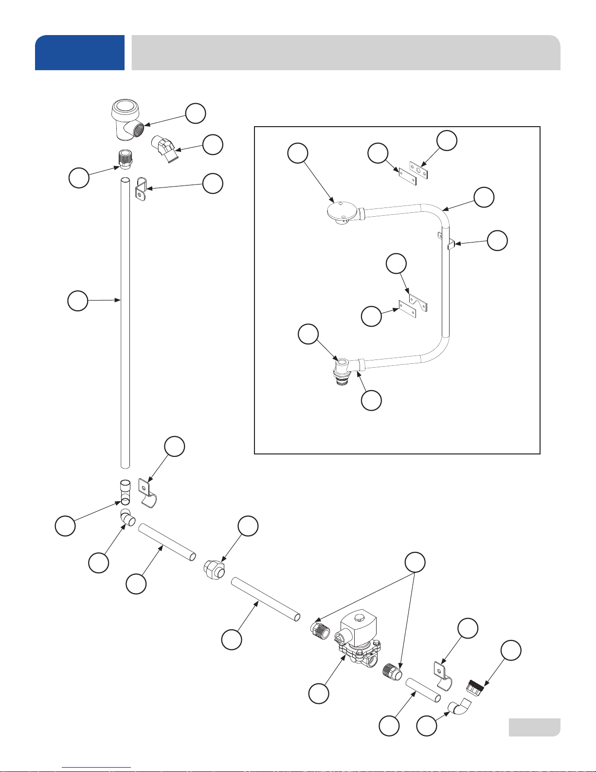
PARTS
LT/LT-H PLUMBING ASSEMBLIES
1
13
2
6
3
14
20
15
21
15
19
16
17
18
7
07610-004-37-13-E
12
11
4
5
6
4
10
5
9
8 7
35
Page 43
NOTICE
PARTS
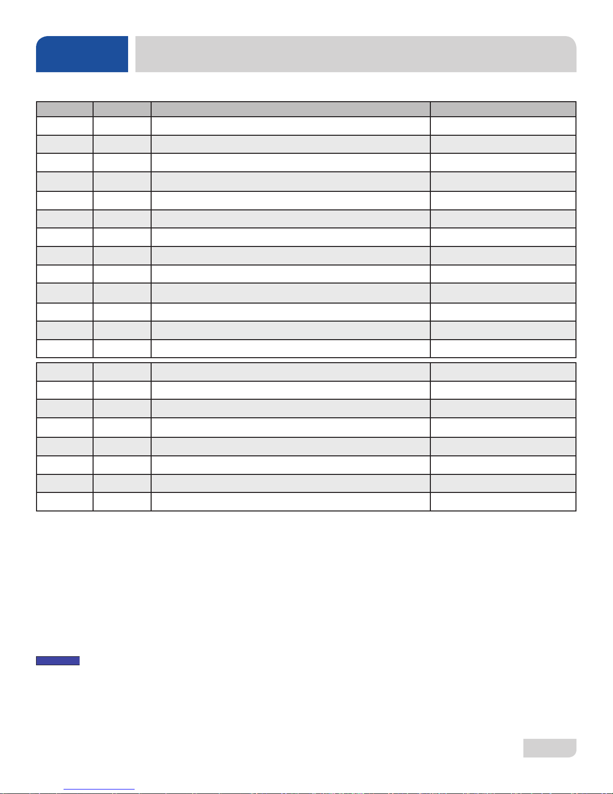
ITEM QTY DESCRIPTION PART NUMBER
1 1 Vacuum Breaker 04820-003-06-13
2 1 Elbow, 1/2" NPT x 3/4" Hose, 45-Degree 04730-003-29-22
3 1 Pipe Clamp 05700-011-38-62
4 2 Pipe Clamp (Side of Unit) 05700-000-35-05
5 1 Union, 1/2" 04730-412-05-01
6 2 Male Adapter 04730-401-03-01
7 2 Elbow, 1/2" 04730-406-31-01
8 1 Copper Pipe, 1/2" x 3" 05700-003-36-25
9 1 Valve, 1/2" 04810-003-71-55
10 1 Copper Pipe, 1/2" x 6 1/2" 05700-002-60-71
11 1 Copper Pipe, 1/2" x 5 1/4" 05700-002-04-92
12 1 Elbow, 1/2", 45-Degree 04730-011-67-77
LT/LT-H PLUMBING ASSEMBLIES
13 1 Copper Pipe, 1/2" x 25 1/2" 05700-011-59-85
14 1 Upper Manifold 05700-031-34-82
15 2 Rinse Plumbing Plate 05700-011-82-86
16 1 Rinse Plumbing Gasket 05330-111-42-81
17 1 Manifold 05700-002-13-75
18 1 Manifold Tube Position Bracket 05700-011-34-63
19 1 Lower Manifold 05700-021-52-80
20 1 O-ring 05330-002-60-69
21 1 Deector Plate 05700-002-62-49
NOTE: Use teon tape on threads. Do NOT use "pipe dope."
07610-004-37-13-E
36
Page 44
PARTS
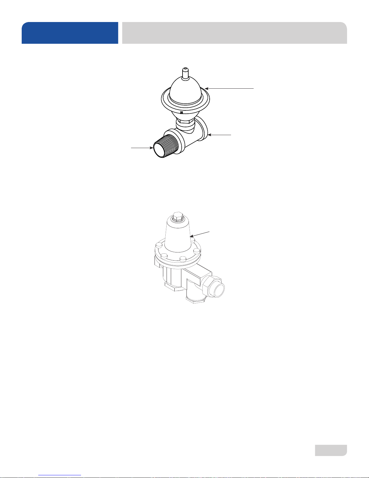
SHOCK ABSORBER (WA TER ARREST OR) OPTION
Nipple, 1/2” NPT, Brass
04730-207-15-00
PLUMBING OPTIONS
Water Arrestor , 1/2”
06685-100-05-00
Tee, 1/2” x 1/2” x 1/2”
04730-211-27-00
Water Arrestor Repair Kit
(Plunger & O-ring)
06401-003-06-23
PRESSURE REGULATOR OPTION
Water Pressure Regulator, 1/2”
05700-100-04-07
07610-004-37-13-E
37
Page 45
PARTS
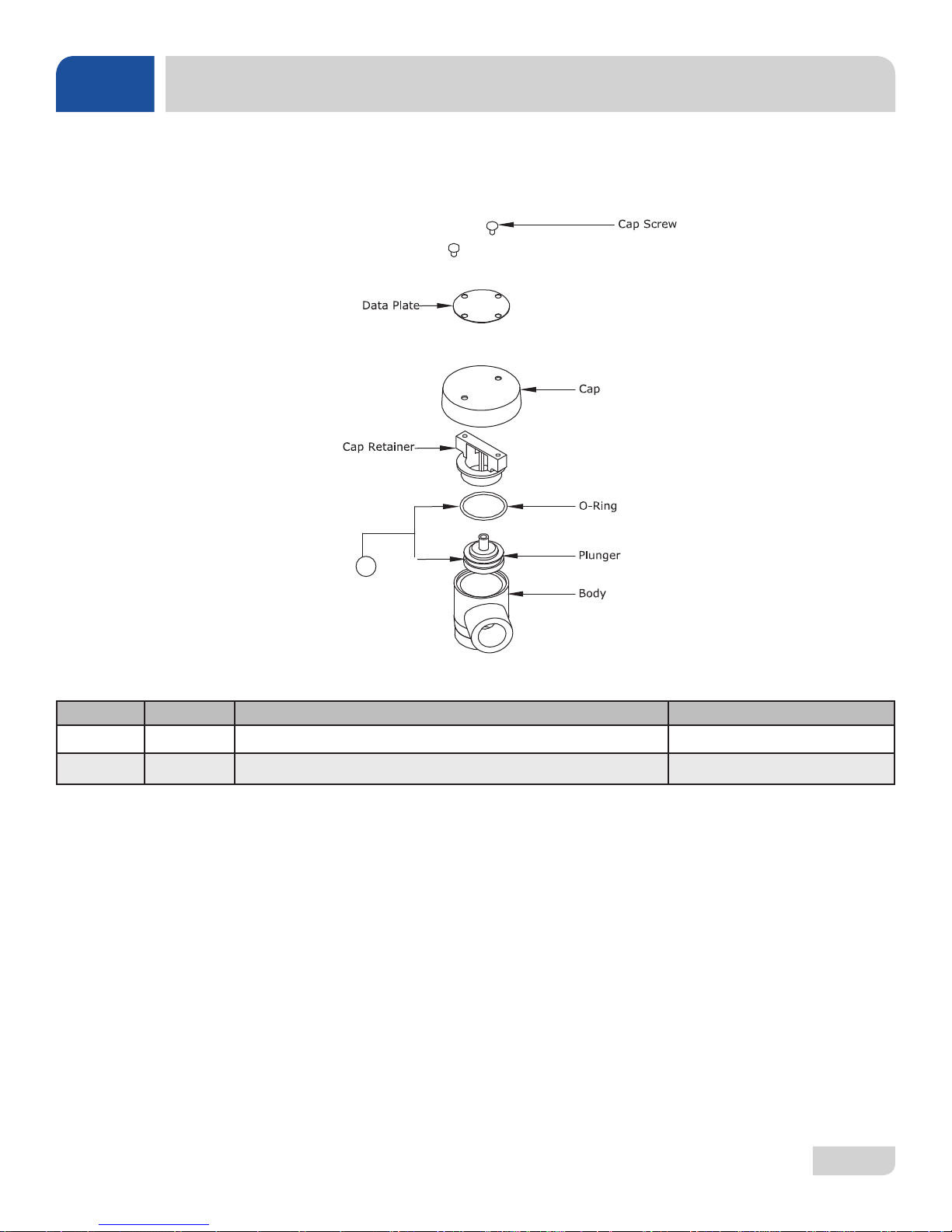
VACUUM BREAKER
Vacuum Breaker Assembly
1
ITEM QTY DESCRIPTION PART NUMBER
1 1 Components of Repair Kit 06401-003-06-23
Complete Vacuum Breaker Assembly 1/2” NPT 04820-003-06-13
07610-004-37-13-E
38
Page 46
PARTS
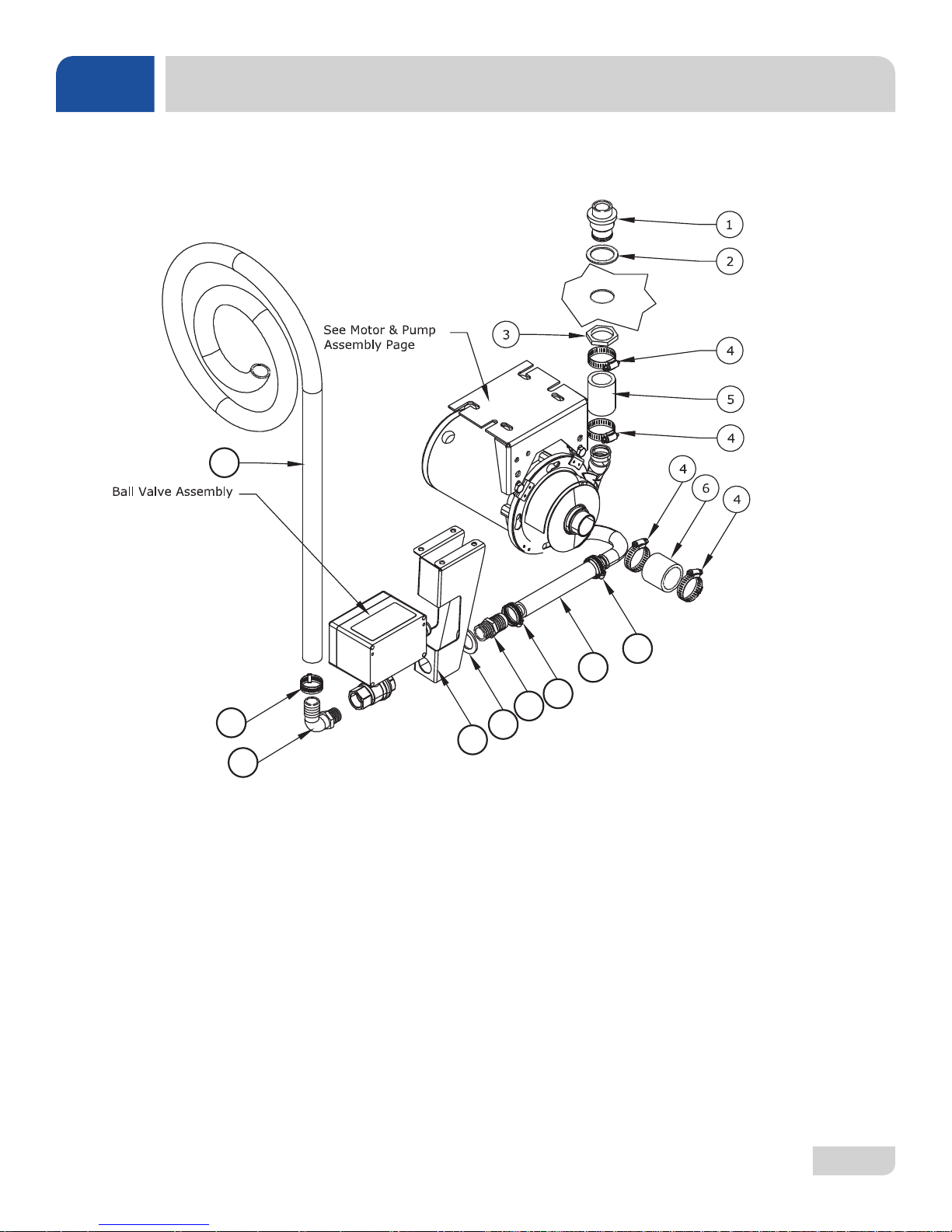
HT
04730-003-34-64
WASH MANIFOLD ASSEMBLY
12
LT/LT-H
04730-003-34-60
7
8
7
9
7
13
10
11
07610-004-37-13-E
39
Page 47
PARTS
ITEM QTY DESCRIPTION PART NUMBER
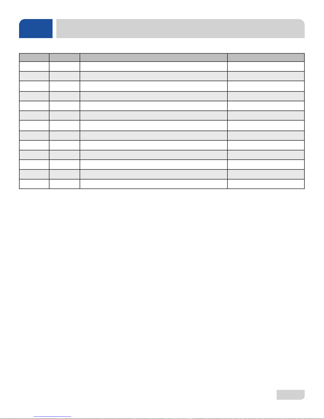
1 1 Hub, Discharge Machine 05700-021-37-90
2 1 Gasket, Manifold 05330-200-23-00
3 1 Nut, Jam 1 1/2-12 05700-000-86-23
4 4 Hose Clamp, 1 5/16” - 2 1/4” #28 04730-719-01-37
5 1 Hose, 1 1/4” x 2 1/4” Reinforced 05700-011-44-48
6 1 Hose, Bottom Manifold Pump 05700-001-22-92
7 3 Clamp, 3/16” to 1 1/2” 04730-719-06-09
8 1 Discharge Hose 05700-004-43-76
9 1 Hosebarb, 1” x 3/4” NPT Polypropylene 04730-011-65-86
10 1 Spacer, Drain Valve 05700-003-31-93
11 1 Bracket, Drain Valve Support 05700-004-35-85
12 1 Hose, 1” ID x 10' Long 05700-011-39-72
WASH MANIFOLD ASSEMBLY
13 1 Hose-barb, 90-Degree 1” x 3/4” NPT 04730-011-65-87
07610-004-37-13-E
40
Page 48
PARTS
8
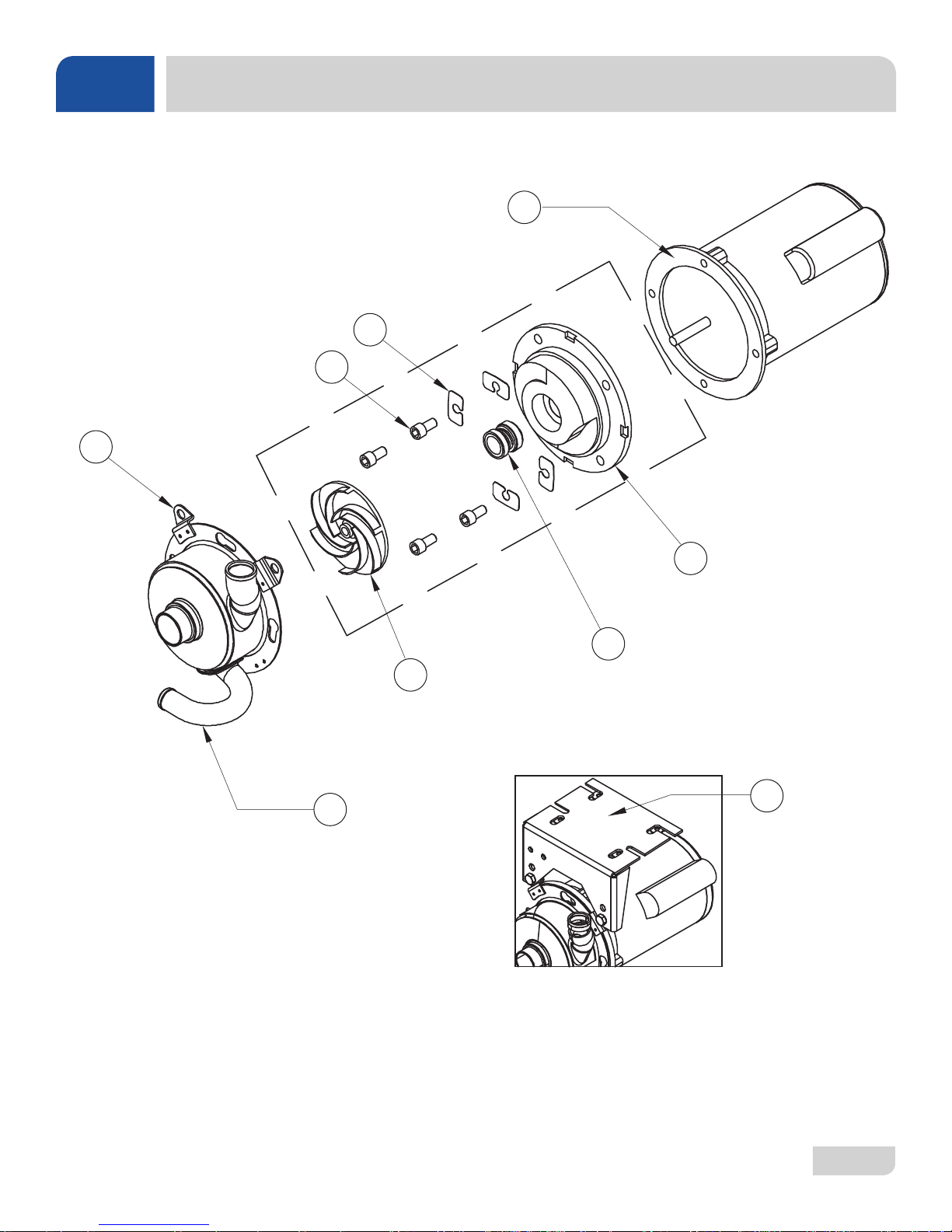
MOTOR & PUMP ASSEMBLY
5
6
7
4
3
2
9
1
07610-004-37-13-E
41
Page 49
PARTS
MOTOR & PUMP ASSEMBLY
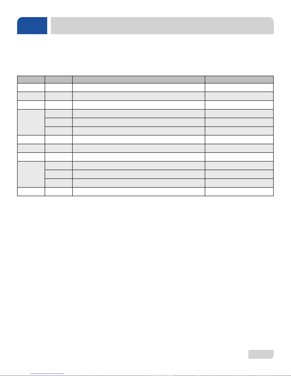
Complete Pump & Motor Assembly, DishStar® HT/LT/LT-H
05700-004-36-57
ITEM QTY DESCRIPTION PART NUMBER
1 1 Pump Casing SS, 60 Hz 05700-002-85-00
2 1 Impeller, 60 Hz 05700-002-81-86
3 1 Mechanical Seal, 60 Hz 05330-002-34-22
1 Seal Plate, 60 Hz 05700-002-81-87
4
5 1 Motor Only, HT/LT/LT-H 06105-004-35-22
6 1 Shim Kit 05700-002-82-58
7 1 Case Capscrew 05305-356-04-00
8
9 1 Mounting Bracket 05700-003-31-58
1 Case O-Ring, 60 Hz 05330-002-81-83
1 Drain Plug (Not Shown) 04730-002-81-89
2 Bolt, 3/8" 05311-276-03-00
2 Lock washer, 3/8" 05311-276-01-00
2 Nut Hex, 3/8-16 05310-276-01-00
07610-004-37-13-E
42
Page 50
PARTS
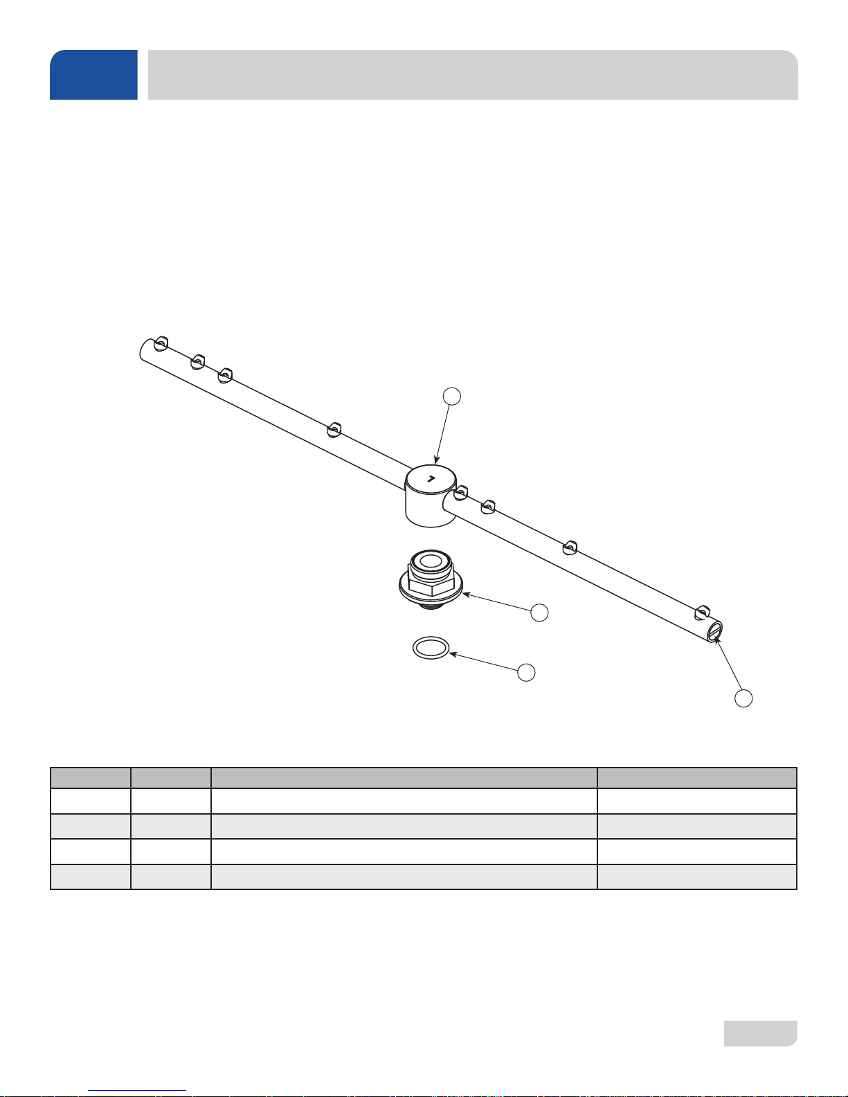
Complete Wash Arm Assembly
1 per Unit on HT
2 per Unit on LT/LT-H
05700-021-39-23
RINSE ARM & WASH ARM ASSEMBLIES
1
2
3
ITEM QTY DESCRIPTION PART NUMBER
1 1 Wash Arm with End-cap 05700-021-46-58
2 1 Bearing, Assembly 05700-021-35-97
3 1 O-Ring 05330-002-60-69
4 2 End-cap, Wash Arm 05700-003-31-59
4
07610-004-37-13-E
43
Page 51
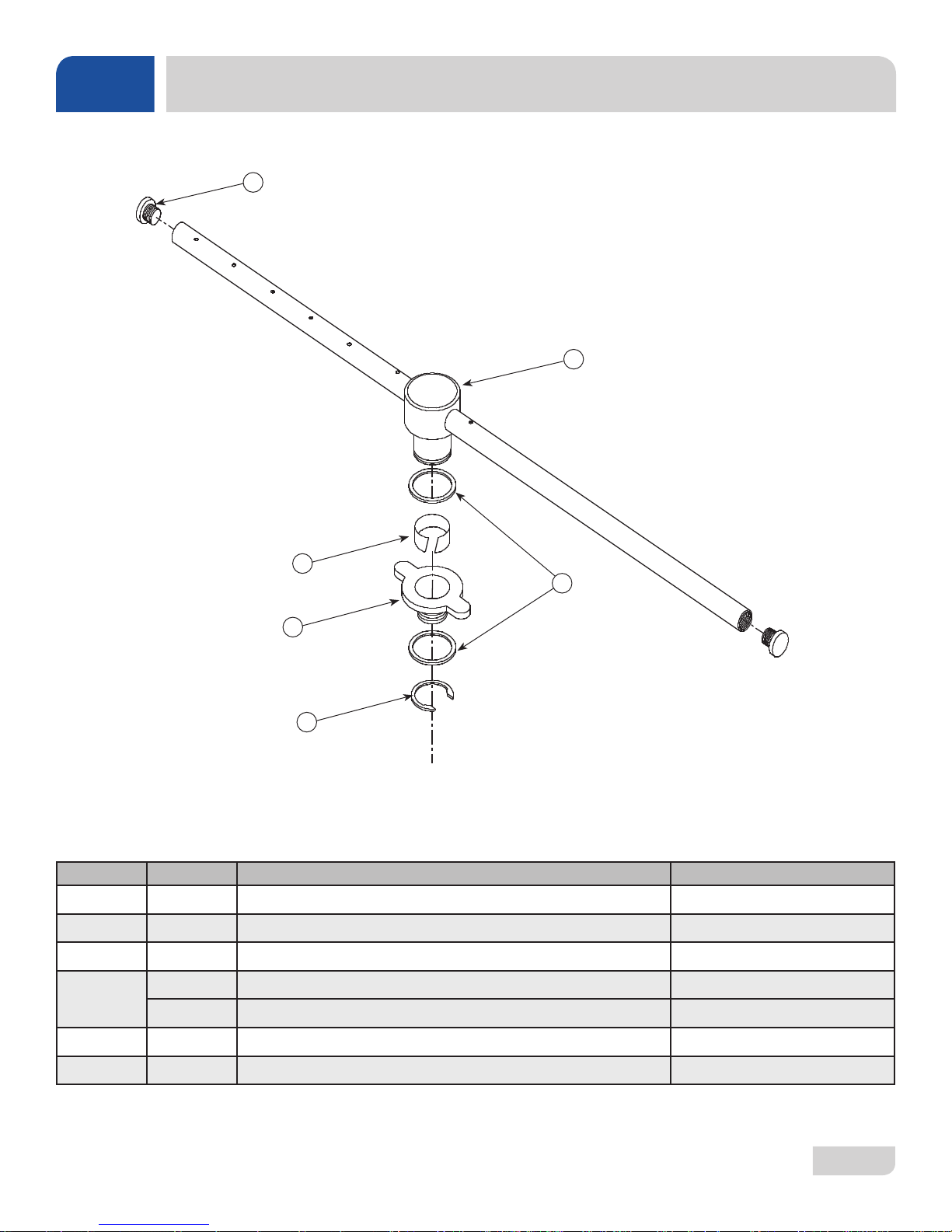
PARTS
RINSE ARM & WASH ARM ASSEMBLIES
6
Rinse Arm Assembly
2 per Unit on HT
0 per Unit on LT/LT-H
05700-031-39-21
Rinse Arm Bearing Kit
5
06401-004-34-89
1
4
2
3
ITEM QTY DESCRIPTION PART NUMBER
1 1 Bearing, Rinse Arm 03120-004-12-13
2 1 Bushing, Rinse Head 05700-021-33-84
3 1 Ring, Retaining, Rinse Head Bushing 05340-112-01-11
4
1 Washer, Rinse Arm 05330-011-42-10
1 O-Ring (Not Shown) 05330-002-60-69
5 1 Rinse Arm 05700-031-38-30
6 2 End-cap, Rinse Arm 04730-111-60-41
07610-004-37-13-E
44
Page 52
F-PLATE, B
19
F-FITTING,
COUPLING
F-BAFFLE,
STUD, 5/16
F-FRONT,A
PARTS
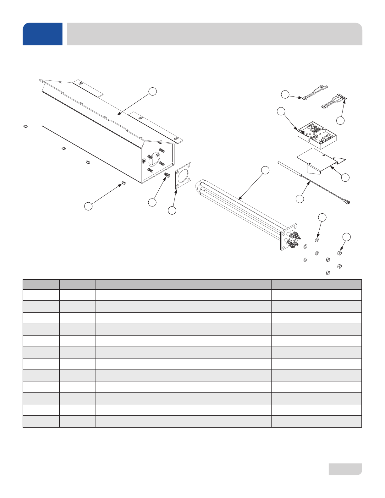
THERMOSTAT & RINSE TANK ASSEMBLY
Complete Rinse Tank Assembly
05700-003-31-94
2
4
9
1
110
211
112
413
114
10
11
8
3
7
ITEM QTY DESCRIPTION PART NUMBER
1 1 Thermostat, Elan Electric Dual 05585-004-17-27
2 1 Rinse Tank Weldment 05700-003-31-95
3 1 Fitting, 1/4" Imperial Brass 05310-924-02-05
12
4 1 208-230 Volt Heater 04540-111-43-21
5 4 Lock Washer, 5/16" Split 05311-275-01-00
6 4 Nut, 5/16-18 SS Hex 05310-275-01-00
7 1 Gasket, Heater 05330-011-47-79
8 9 Locknut, 1/4-20 SS Hex with Nylon Insert 05310-374-01-00
5
6
9 1 Harness, 4-Connector 05700-004-36-24
10 1 Harness, 5-Connector 05700-004-36-25
11 1 Thermostat Mounting Bracket 05700-004-21-55
12 1 Probe, Thermister 4" 06685-004-17-26
07610-004-37-13-E
45
Page 53
PARTS
7
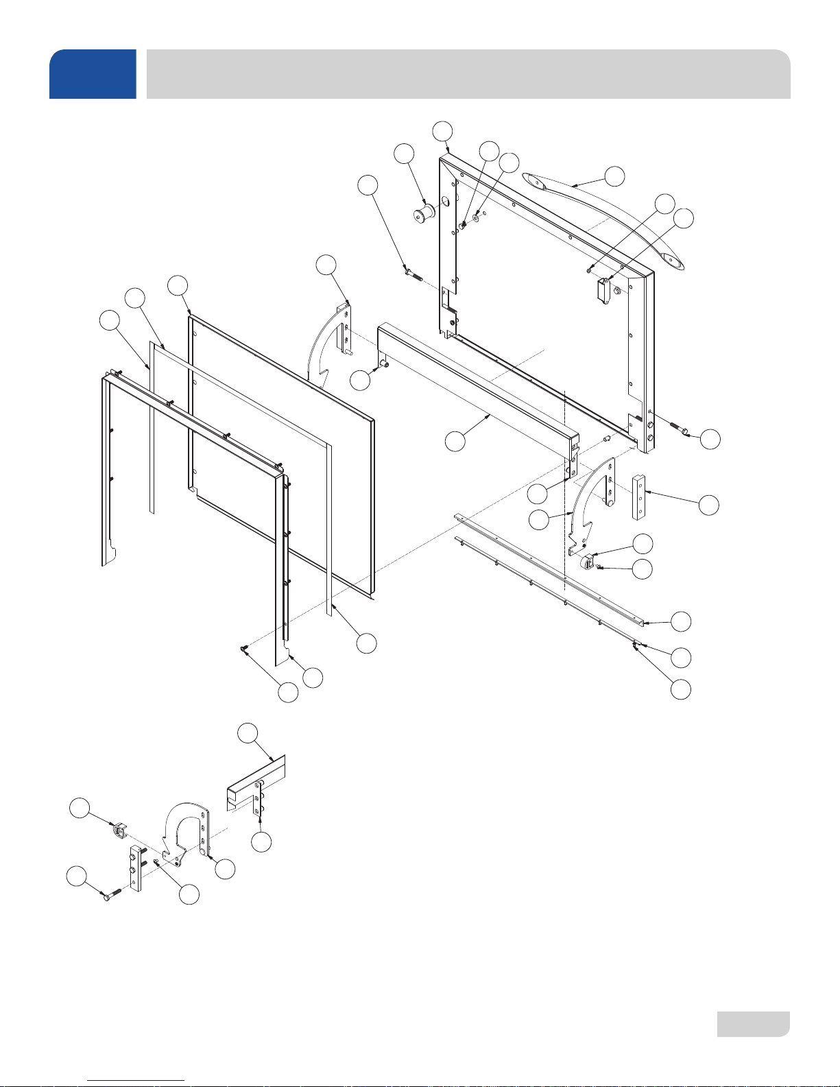
DOOR ASSEMBLY
1
(2 PLC'S)
17
21
(3 PLC'S)
12
13
6
18
3
(2 PLC'S)
5
15
18
11
9
(2 PLC'S)
4
19
21
(3 PLC'S)
8
(12 PLC'S)
16
(2 PLC'S)
10
(2 PLC'S)
2
(2 PLC'S)
22
7
23
20
14
(12 PLC'S)
15
10
18
21
11
2
24
(6 PLC'S)
07610-004-37-13-E
46
Page 54
PARTS
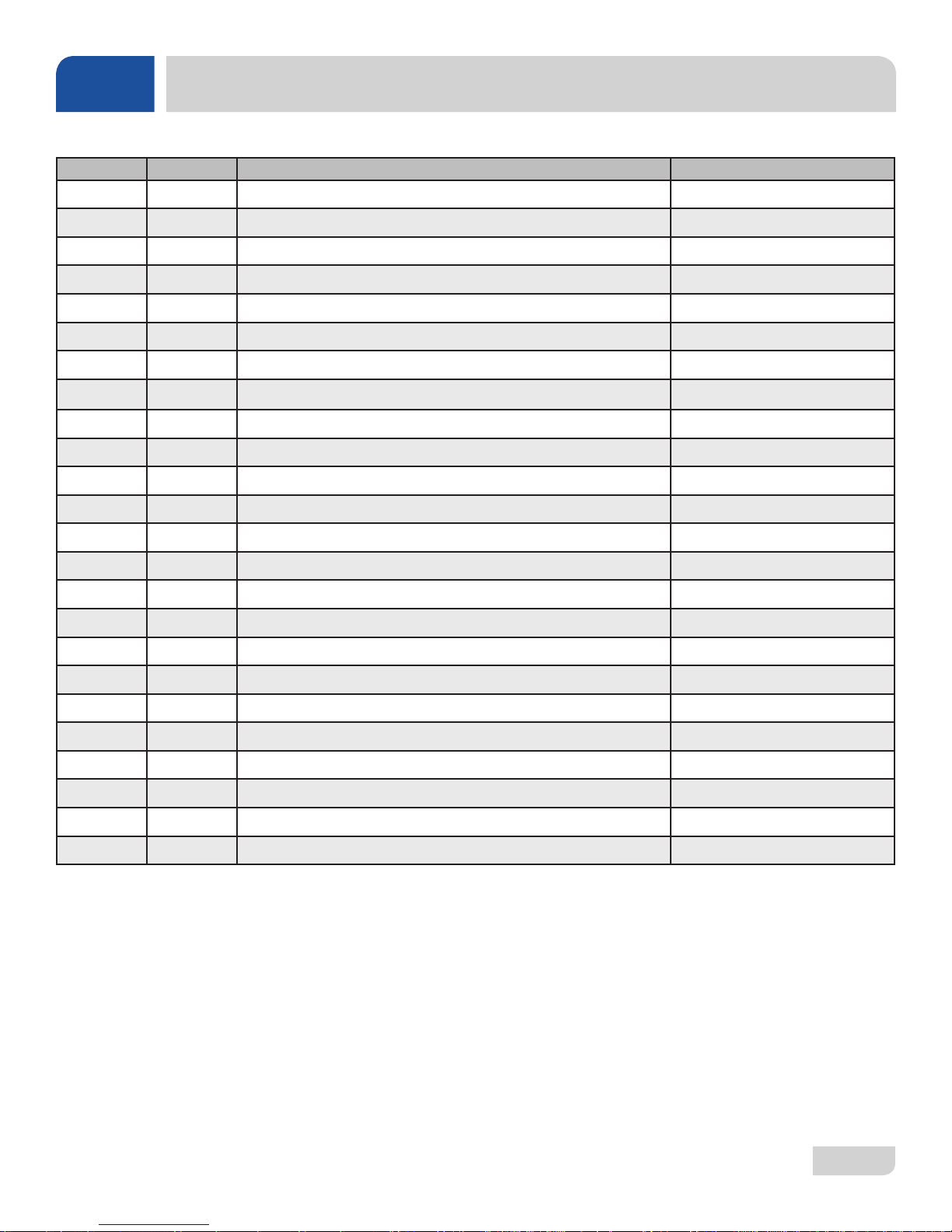
ITEM QTY DESCRIPTION PART NUMBER
1 1 Outer Door Weldment 05700-004-36-55
2 2 Screw, 10-32 x 1/4" 05305-173-01-00
3 2 Bolt, 1/4-20 x 3/8" Hex 05305-274-20-00
4 2 Nut, Lock 6-32 Hex with Nylon Insert 05310-373-03-00
5 2 Washer, SS 1/4-20 ID 05311-174-01-00
6 1 Gasket, Door 20" 05330-003-58-35
7 2 Gasket, Door 17 1/8" 05330-003-58-36
8 Item intentionally left blank.
9 1 Door Handle 05700-003-26-62
10 2 Stop, Door Hinge 05700-003-32-55
11 1 Hinge, Left 05700-003-32-71
12 1 Hinge, Right 05700-003-32-72
13 1 Inner Door 05700-003-33-21
DOOR ASSEMBLY
14 12 Screw, 10-32 x 1/2" Pan Phillips Head 05305-011-44-52
15 1 Baffle, Door 05700-003-33-38
16 2 Hinge Spacer 05700-003-33-42
17 1 Switch Assembly 05700-003-34-80
18 2 Retaining Plate 05700-011-44-37
19 1 Magnet 05930-002-88-42
20 1 Channel, Door Seal 05700-003-55-49
21 6 Screw, 1/4-20 x 1 1/2" Hex 05305-274-23-00
22 1 Gasket, Door L 05330-004-36-05
23 1 Gasket Clamp 05700-004-36-56
24 6 Pop Rivet, 1/8" x 3/8" 05320-003-06-98
07610-004-37-13-E
47
Page 55
PARTS
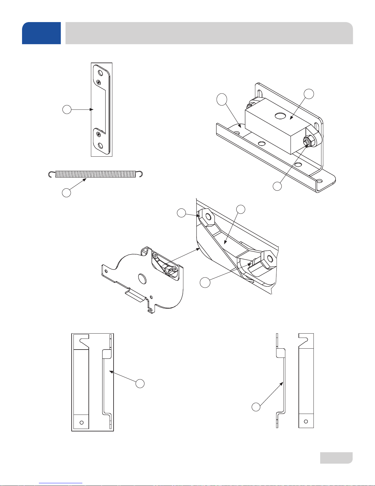
MISCELLANEOUS DOOR COMPONENTS
10
1
8
2
7
6
9
07610-004-37-13-E
5
3
4
48
Page 56
PARTS
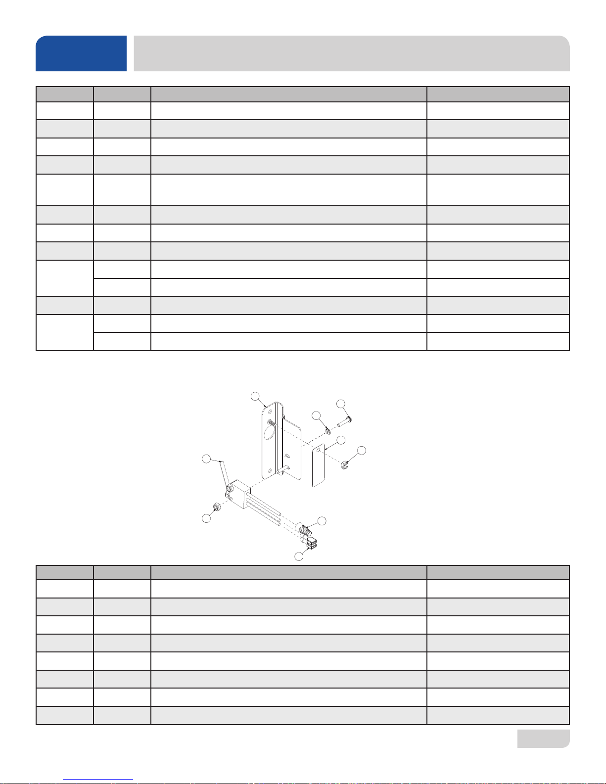
MISCELLANEOUS DOOR COMPONENTS
ITEM QTY DESCRIPTION PART NUMBER
1 1 Switch Mounting Plate Assembly 05700-003-33-54
2 1 Door Spring 05700-003-32-85
3 1 Cover, Left Hinge Weldment 05700-004-36-80
4 1 Cover, Right Hinge Weldment 05700-004-36-81
Hinge Components secured with Locknut, 1/4-20 SS Hex
with Nylon Insert
05310-374-01-00
5 2 O-Ring 05330-003-32-34
6 1 Latch Spring 05700-003-32-32
7 2 Latch Nut 05700-003-32-33
2 Hardware: Locknut, 6-32 SS Hex with Nylon Insert 05310-373-03-00
8
2 Screw, 6-32 x 1/4” Flat Head 05305-171-01-00
9 1 Door Switch 05930-003-31-44
1 Door Switch Bracket 05700-003-31-43
10
Door Switch & Bracket Assembly 05700-003-32-21
Complete Cycle Switch Assembly
05700-004-36-00
1
5
8
(2 PLC'S)
7
6
(2 PLC'S)
2
ITEM QTY DESCRIPTION PART NUMBER
1 1 Switch, Cover Plate 05700-004-35-99
2 3 Nut, Lock 6-32 Hex with Nylon Insert 05310-373-03-00
3 1 Wire Nut, Blue Metal 05945-111-01-00
4 2 Term,190030013 .187 Pink Reel 05940-111-46-18
5 1 Switch, Cherry Door 05930-303-38-00
6 1 Lever Spring, Start Switch 05700-004-35-98
7 2 Screw, 6-32 x 5/8" 05305-011-39-85
8 2 Lockwasher, #6 Ext.Tooth 05311-271-02-00
07610-004-37-13-E
2
(2 PLC'S)
4
3
(2 PLC'S)
49
Page 57
PARTS
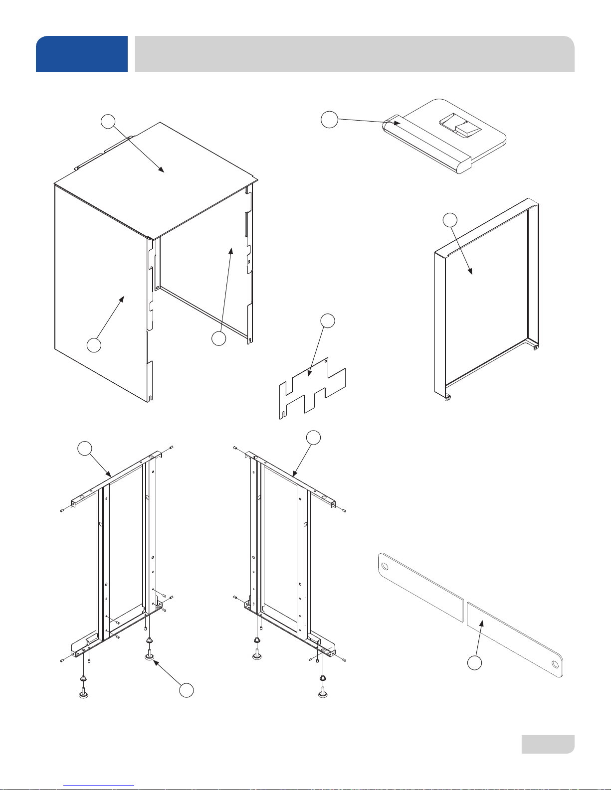
FRAME & PANEL COMPONENTS
1
2
3
10
8
9
6
4
7
5
07610-004-37-13-E
50
Page 58
PARTS
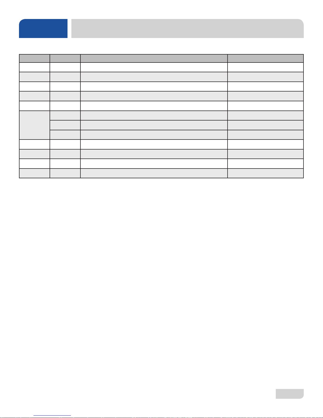
ITEM QTY DESCRIPTION PART NUMBER
1 1 Top Shroud Weldment 05700-003-37-06
2 1 Left Shroud Weldment 05700-003-37-04
3 1 Right Shroud Weldment 05700-004-36-82
4 1 Left Frame Weldment 05700-003-31-91
5 1 Swivel Feet 05340-108-02-00
1 Right Frame Weldment 05700-003-31-90
FRAME & PANEL COMPONENTS
6
7 2 Bottom Strap 05700-003-92-20
8 1 Optional Back Panel 05700-003-33-55
9 1 Standard Back Panel 05700-004-36-83
10 2 Shroud Plug 05700-003-32-50
4 Hardware: Nut, 1/4-20 Serrated Hex 05310-959-03-00
4 Nut, 5/16-18 Cad Spine 05310-959-03-00
07610-004-37-13-E
51
Page 59
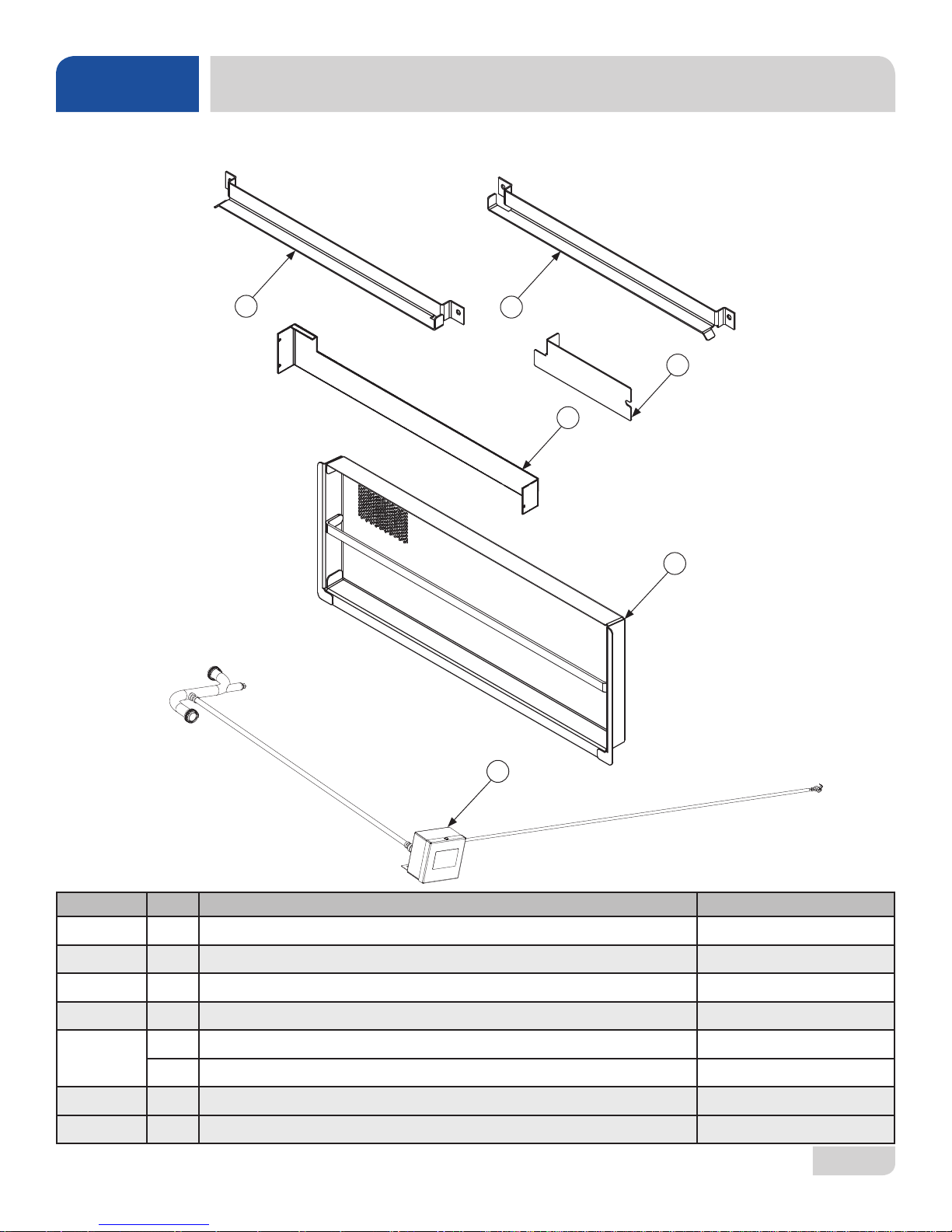
PARTS
Parts are not shown to scale in relation to each other.
MISCELLANEOUS PARTS
1
2
4
3
5
ITEM QTY DESCRIPTION PART NUMBER
Components secured with Locknut, 1/4-20 SS Hex with Nylon Insert 05310-374-01-00
1 1 Rail, Left Rack 05700-031-37-88
2 1 Rail, Right Rack 05700-031-37-88
3 1 Splash Shield 05700-003-33-51
1 Strainer Spacer 05700-002-70-60
4
Attaches with: Nut, Nylon Wing, 1/4-20 05310-994-01-00
5 1 Strainer Weldment 05700-031-35-81
6 1 Drain Quench Kit (DishStar HT) 06401-002-59-99
07610-004-37-13-E
6
52
Page 60
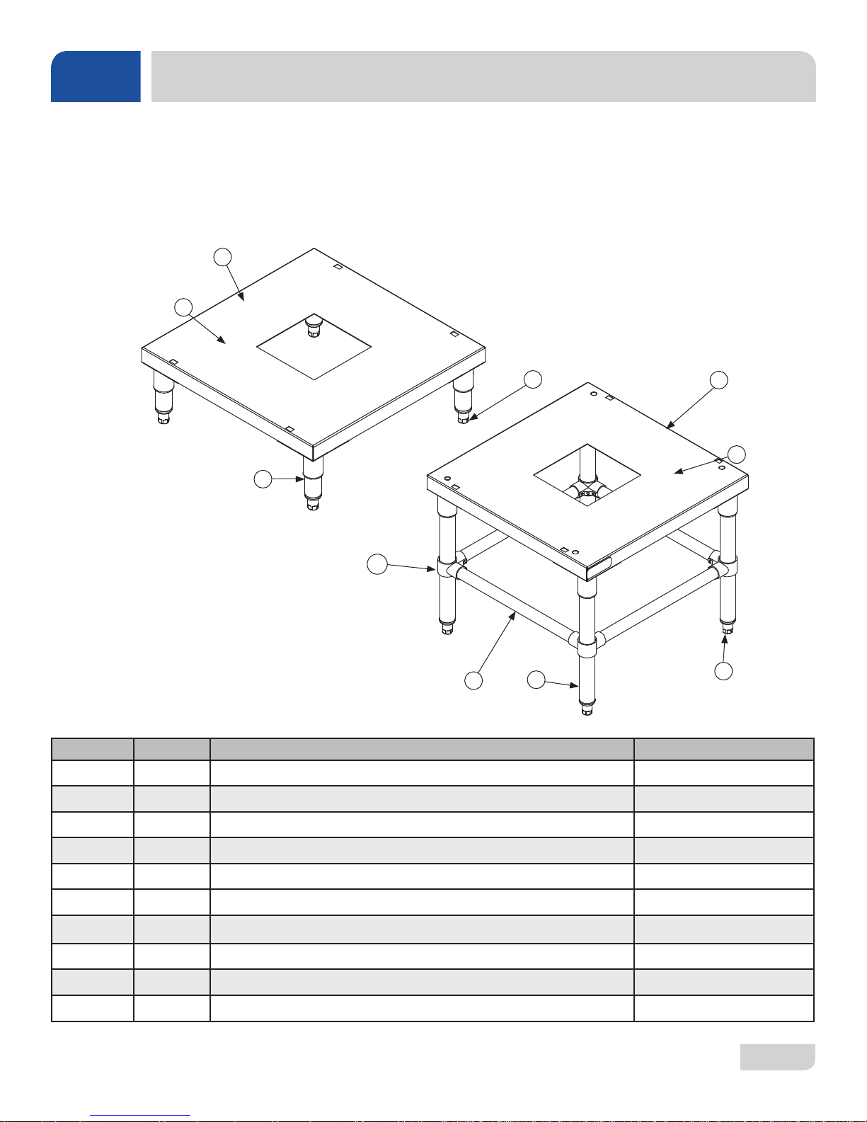
PARTS
STANDS & COMPONENTS
INSTALLATION
INSTRUCTIONS
1
2
3
To install the stand, rst remove the adjustable feet from the machine. Place machine
on table and use the square mounting holes to line-up the machine. Re-insert the
adjustable feet through bottom of table top and tighten to lock machine to table.
4
5
6
10
9
ITEM QTY DESCRIPTION PART NUMBER
1 1 6” Stand Assembly 05700-003-34-24
2 1 Stand 05700-002-88-82
3 4 6” Leg 05700-021-61-10
4 4 Bullet Foot 05340-108-01-03
5 1 18” Stand Assembly 05700-003-34-25
6 1 Stand 05700-002-88-82
7 4 Bullet Foot 05340-108-01-03
8 4 18” Leg 05700-002-89-47
8
7
9 4 Cross Brace 05700-003-25-90
10 4 Cross Member Bracket 04730-003-25-89
07610-004-37-13-E
53
Page 61
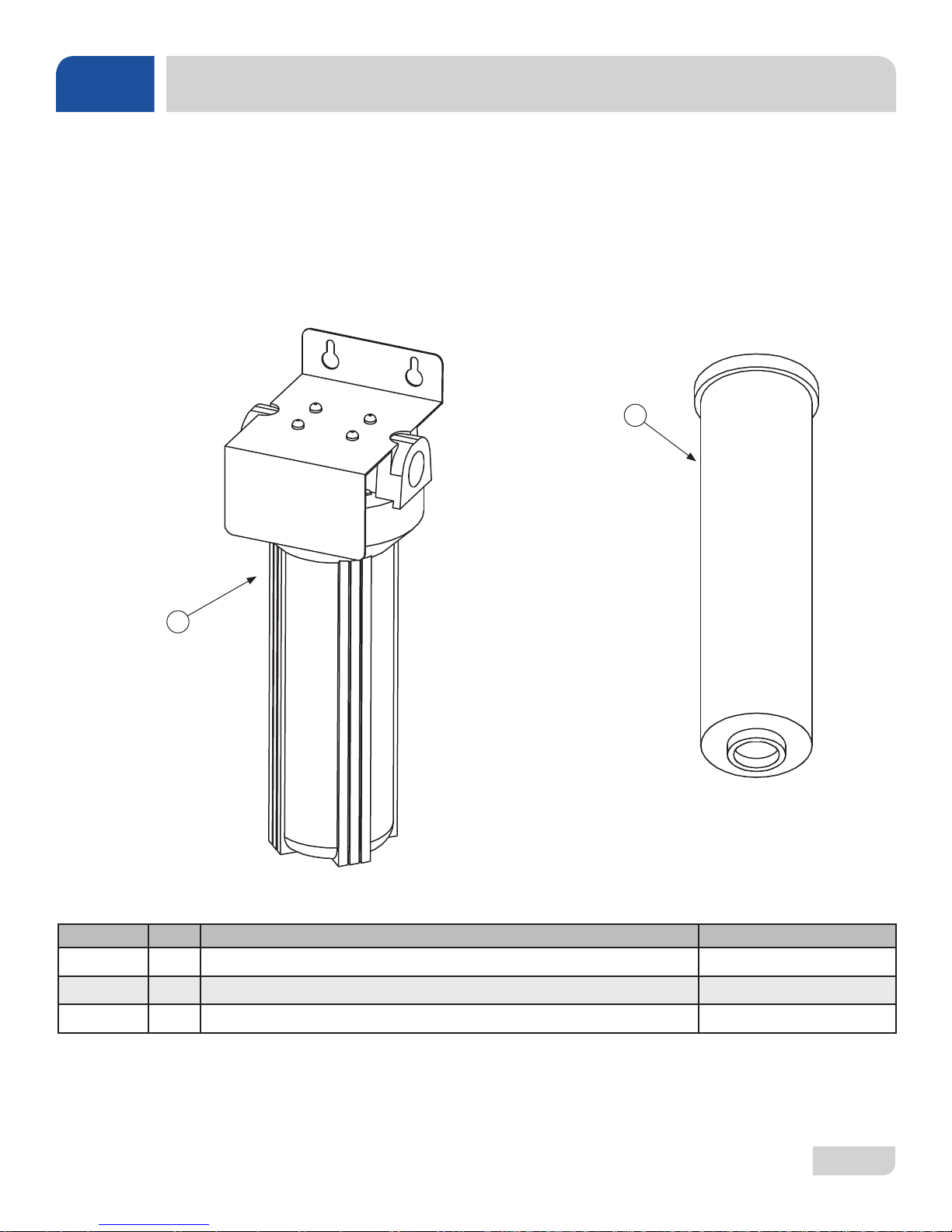
PARTS
HTS-11 (SCALE PREVENTION & CORROSION DEVICE)
INSTALLATION
INSTRUCTIONS
Must be installed vertically. The provided bracket is to be secured to the wall.
Observe proper inlet/outlet water directions. Flow directions are molded into the top
of the head. Line pressure should be released before changing cartridges. Deliming
of equipment before installation is recommended.
2
1
ITEM QTY DESCRIPTION PART NUMBER
1 1 Kleeneware HTS-11 System 04730-003-28-03
2 1 Replacement Cartridge (inspect at least every 6 months) 04730-003-28-04
Replacement Test Strip (not shown) 06401-003-28-06
07610-004-37-13-E
54
Page 62
PARTS
A GO Box is a kit of the most-needed parts for a particular model or model family to successfully effect a repair in the rst
call, 90% or more of the time.
DishStar® HT Go Box Kit
06401-004-40-87
ITEM QTY DESCRIPTION PART NUMBER
1 2 Squeeze T ube, Rinse-aid 05700-011-65-21
2 2 Squeeze Tube, Detergent and Sanitizer 05700-003-22-89
3 12 Tubing, Blue Plastic 04720-601-11-00
4 12 Tubing, Red Plastic 04720-601-12-00
5 1 Timer, Universal 05945-003-75-23
6 2 Bearing, Rinse Arm 03120-004-12-13
7 2 Snap Ring, Retaining, Rinse Arm 05340-112-01-11
8 4 W asher , Rinse Arm 05330-011-42-10
9 1 Harness, 10-Wire Solid Fused Timer 05999-003-87-88
GO BOX KIT
10 2 End-cap, Rinse Arm 04730-111-60-41
11 4 Bearing Assembly, Wash Arm 05700-021-35-97
12 4 End-cap, Wash Arm 05700-003-31-59
13* 1 Pump/Motor Assembly 06105-002-72-75
14 1 Auto/Manual, ON/OFF Switch 05930-011-49-55
15 1 Solenoid Valve, 1/2" 04810-003-71-56
16 1 Pump Seal 05330-002-34-22
17 2 Shim Kit 05700-002-82-58
* Special pricing when purchased with a Go Box Kit. Call for details.
07610-004-37-13-E
55
Page 63
PARTS
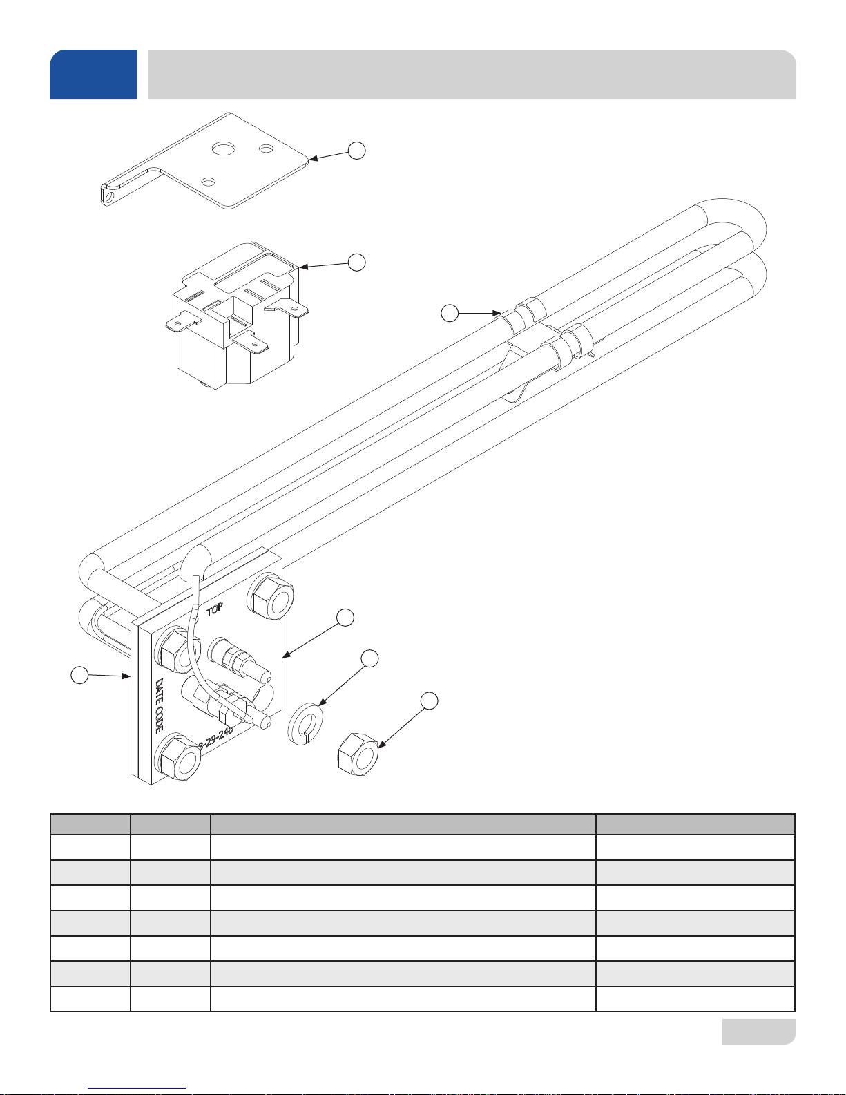
LT-H OPTIONAL HEATER COMPONENTS
1
2
3
4
5
7
6
ITEM QTY DESCRIPTION PART NUMBER
1 1 Thermostat Bracket 05700-004-36-37
2 1 High Limit Thermostat 05930-004-33-12
3 1 Probe Bracket 05700-004-38-45
4 1 Wash Heater, 115 V, 1.5 kW 04540-004-33-76
5 4 Lockwasher, Split, 5/16" 05311-275-01-00
6 4 Nut, Hex 5/16-18 05310-275-01-00
7 1 Wash Heater Gasket 05330-011-61-34
07610-004-37-13-E
56
Page 64
PARTS
8
2
4
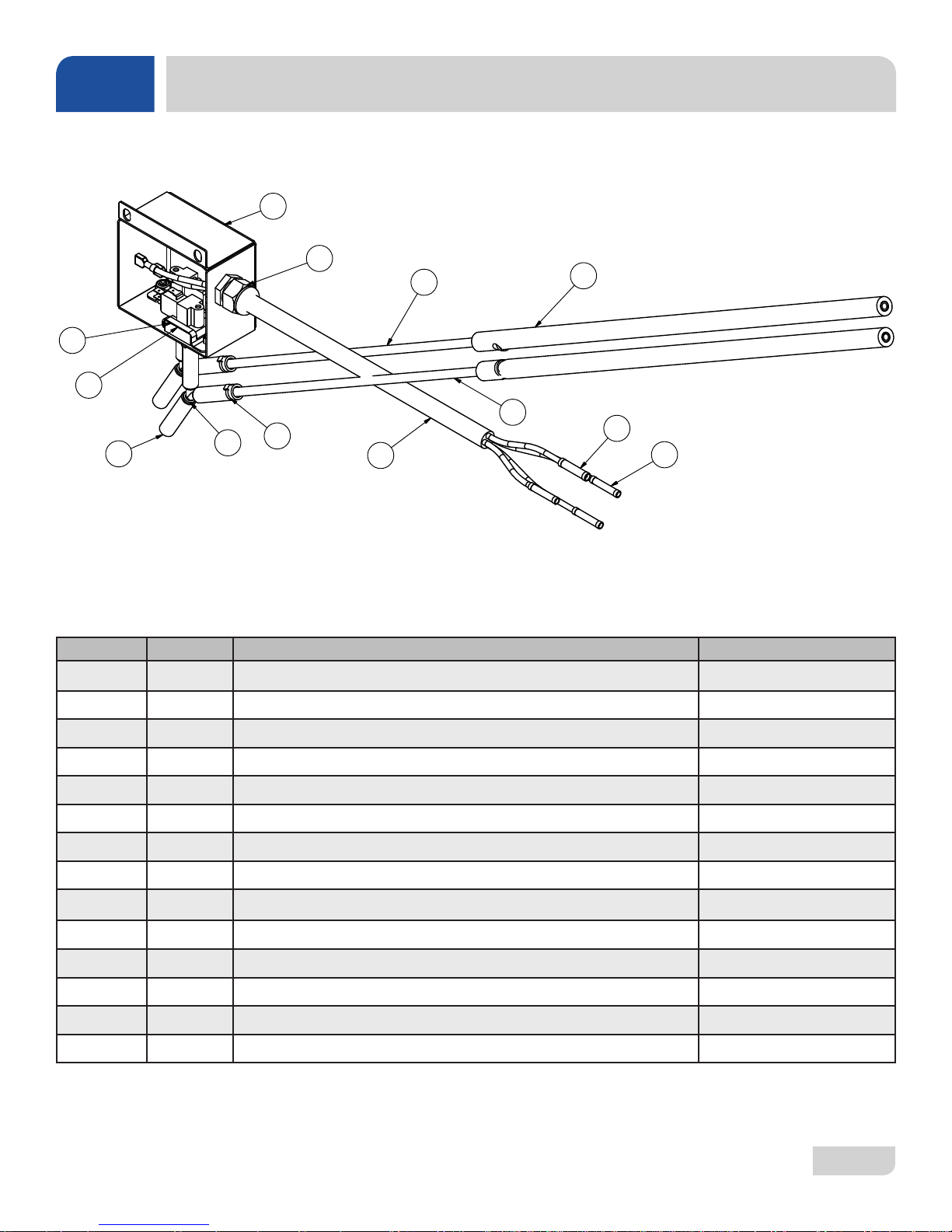
LT/LT-H VACUUM SWITCH ASSEMBLY
1
7
5
6
10
3
11
12
9
13
ITEM QTY DESCRIPTION PART NUMBER
Complete Assembly 05700-003-55-98
1 1 Box, Vacuum Switch 05700-003-55-96
2 2 Switch, Vacuum 06685-003-36-13
3 2 Wye, 1/4” Barbed PVDF 04730-003-36-14
4 6 Tubing, Clear 5/16" ID 04710-003-53-26
5 1 Tube, Red 1/4" OD x 100" Long 05700-003-03-45
6 1 Tube, White 1/4" OD x 100" Long 05700-003-03-45
7 1 Fitting, Liquidtite .231" x .394" Heyco 05700-003-20-67
8 2 Pressure Switch Bracket 05700-003-53-03
9 2 Spice, Blue Butt 05940-200-11-44
10 6 Locknut, 10-24 x 3/8" Phillips Truss 05945-602-01-16
11 14 Cable, 18 GA/5 Con 46” 05700-003-55-97
12 3 Tube Stiffener 05700-002-66-49
13 2 Splice, Red Butt 05940-200-26-00
07610-004-37-13-E
57
Page 65
PARTS
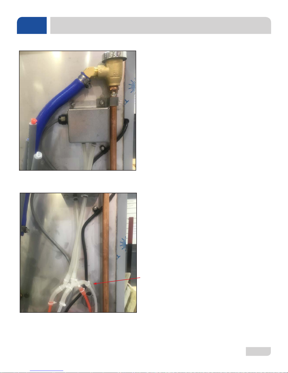
LT/LT-H VACUUM SWITCH ASSEMBLY INSTALL
Remove locknut on plumbing support bracket and mount
switch box over existing stud. Reinstall bracket and route red
and white tubes behind blue hose as shown.
Route gray cable down back and under the tub along inlet
plumbing, remove wires from existing pressure switches, and
connect to gray cable per note below.
Detergent Switch (Red Tube)
1. Connect black wire from gray cable to black/yellow wire
from switch.
2. Connect brown wire from gray cable to blue wire from
switch.
Sanitizer Switch (White Tube)
1. Connect white wire from gray cable to white/yellow wire
from switch.
Back of machine showing use of existing mounting hardware for
installation of vacuum switch assembly.
2. Connect red wire from gray cable to blue wire from switch.
After cutting the existing red and white tube approximately 12”
above the gray tube stiffener , insert the cut ends into the clear
tubes as shown.
07610-004-37-13-E
58
Page 66
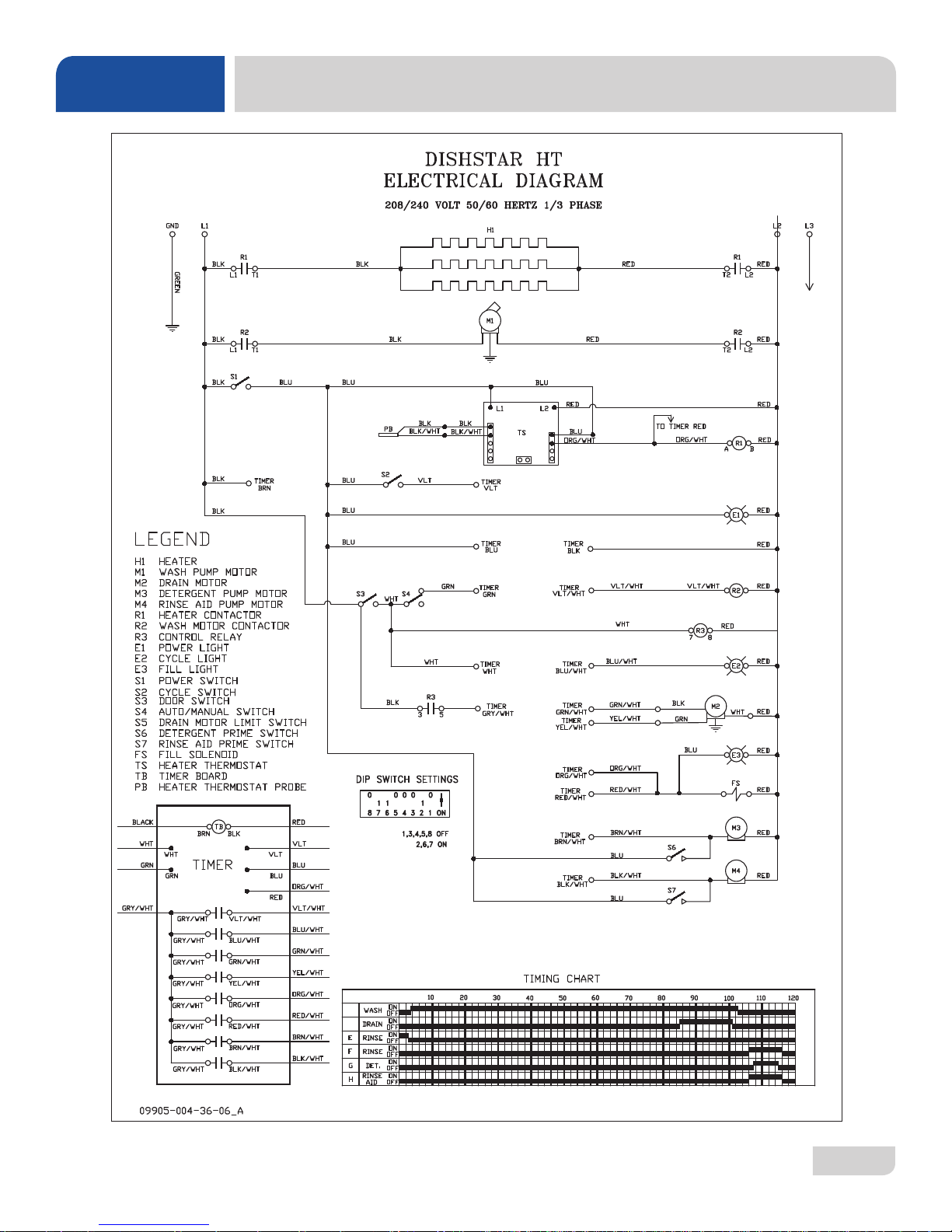
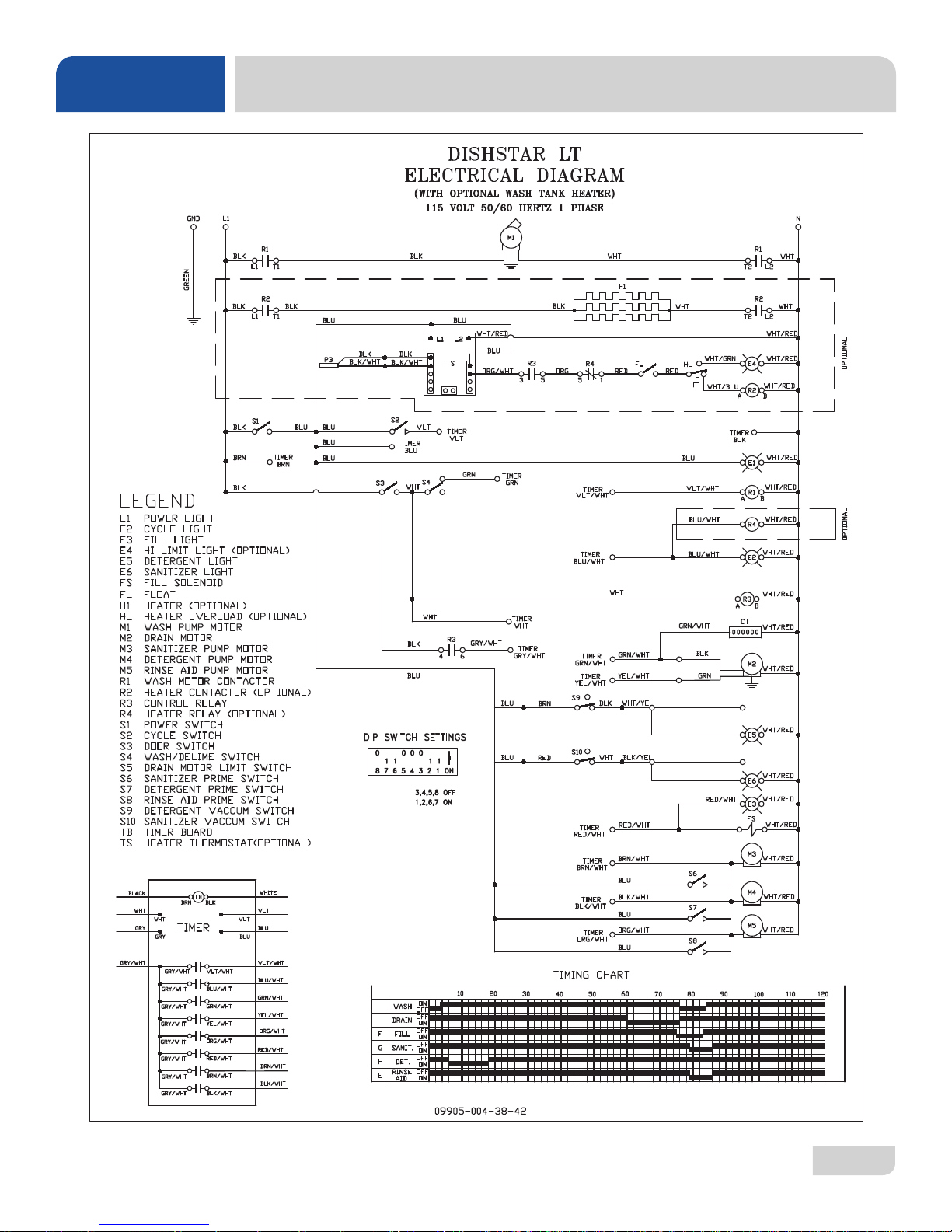
SCHEMATICS
DISHSTAR® HT
07610-004-37-13-E
59
Page 67
SCHEMATICS
DISHSTAR® LT/LT-H
07610-004-37-13-E
60
Page 68

Jackson WWS, Inc. • 6209 N. US Hwy 25E • Gray, KY 40734 USA
1.888.800.5672 • www.jacksonwws.com
DishStar® HT/LT Manual • 07610-004-37-13-E
61
61
61
 Loading...