

Page 1

READ THESE INSTRUCTIONS THOROUGHLY!
Follow the instructions STEP-BY-STEP, and your
installation will be trouble free. If in doubt, CALL
1-888-888-4079. We suggest that as you proceed through the installation, you should read a
few steps ahead in the instructions so you are
certain to catch all notes and warnings.
ATTENTION SUPERCHARGER INSTALLER!
Before proceeding with the installation, it is
important to know that to validate the 2 year,
100K warranty on your new J/R supercharger,
you must completely fill out the Moss Motors /
Jackson Racing warranty card that comes in
every kit, including serial number which is on a
small white ‘bar code’ label on the body of the
supercharger. Write down all of the numbers
which appear on that label in the appropriate
space on the warranty card. Be certain to do this
now because once your supercharger is
installed, it may be almost impossible to retrieve
that serial number.
SPECIAL NOTE: Jackson Racing Supercharger
Systems are designed to be installed by individuals with good mechanical sense and with the
proper tools. Use your discretion--if you are not a
competent mechanic, do not attempt this installation.
TOOLS REQUIRED: Most of these tools are
available at your local hardware or auto parts
stores.
17mm, 14mm, 13mm, 12mm, 10mm & 8mm
sockets
Deep sockets (14mm or 9/16”, 10mm)
Phillips and Standard screwdrivers
Multi-purpose pliers
10mm, 12mm, and 17mm open end wrenches
Timing light
A shop manual is useful.
WARNING: Once the installation is complete,
CHECK AND RECHECK ALL fuel system connections for possible leaks before operating the
vehicle. 91-octane gasoline (or higher) is
required when running a supercharger.
During this installation process, you will reuse
some parts or hardware and not reinstall others.
It is recommended that you make space for
those that you will reuse, and a separate space
for those that you will not reinstall. In addition,
you should save the parts that will not get reused
in case you ever have reason to convert the
engine back to stock.
Enclosed is a set of labels that we suggest you
use to label the electrical connectors that you will
be unplugging.
Installation Instructions
SUPERCHARGER
with PowerCard
‘90-’93 Mazda Miata
Part# 999-156, 999-157, 999-158, 999-159
440 Rutherford St. P.O. Box 847 Goleta, CA 93117
1-888-888-4079 • FAX 805-692-2523 • www.supercharger.com
999-156, 999-157, 999-158 & 999-159 -1- Revised 06/08
Page 2
1.0 DISASSEMBLY
1.1 Release the airflow meter harness 7-pin connector by lifting the small wire clip that runs
around the rectangular base of the connector.
Remove the stock air flow meter, air filter box
and intake snorkel. Remove the air flow meter
from the air box. Store the air box, filter, and
snorkel away. Move the air flow meter to a safe
place on a worktable.
1.2 Remove the molded rubber elbow and hard
plastic tube that lead from the throttle body to the
airflow meter. If you have cruise control, you will
also have to remove the vacuum line from the
intake manifold nipple and from the points where
it attaches to the hard plastic intake tube.
Remove the cruise control vacuum line from the
cruise actuator as well and save it for use in a
later step.
1.3 Remove the chrome crankcase vent pipe that
is attached to the front of the cam cover and the
rubber hose that leads into the cam cover (Figure
1.4). These can be stored away. However, find
the small restrictor inside the rubber hose that
ran from the cam cover to the chrome tubing. It
can be felt as a lump in the straight section of the
hose near the chrome tube end. Persuade it out
by gently clamping the hose with a pair of pliers
just behind the “lump”. Save this restrictor for
step #7.8. Re-install the chrome bolts that held
the tubing in place. Store the chrome tube and
Mazda hoses away.
2.0 THROTTLE BODY
2.1 Remove the throttle body (Figure 1.4) by
releasing the two electrical connectors (one has
a spring wire, one has a plastic lever clip), the
two small coolant hoses on either side of the
lower Idle Control System (ICS) valve, and the
four bolts.
TIP: THE SPRING HOSE CLAMPS FROM
MAZDAARE BEST REMOVED BY
APPROACHING FROM THE SIDE WITH NEEDLE NOSE PLIERS. GRASP ALL THREE
T ANGS AT ONCE AND COMPRESS THEM
TOGETHER. THIS IS EASIER TO DO WITH
THE THROTTLE BODY ALREADY LOOSE
FROM THE INTAKE MANIFOLD.
999-156, 999-157, 999-158 & 999-159 -2- Revised 06/08
Supercharger Installation Instructions
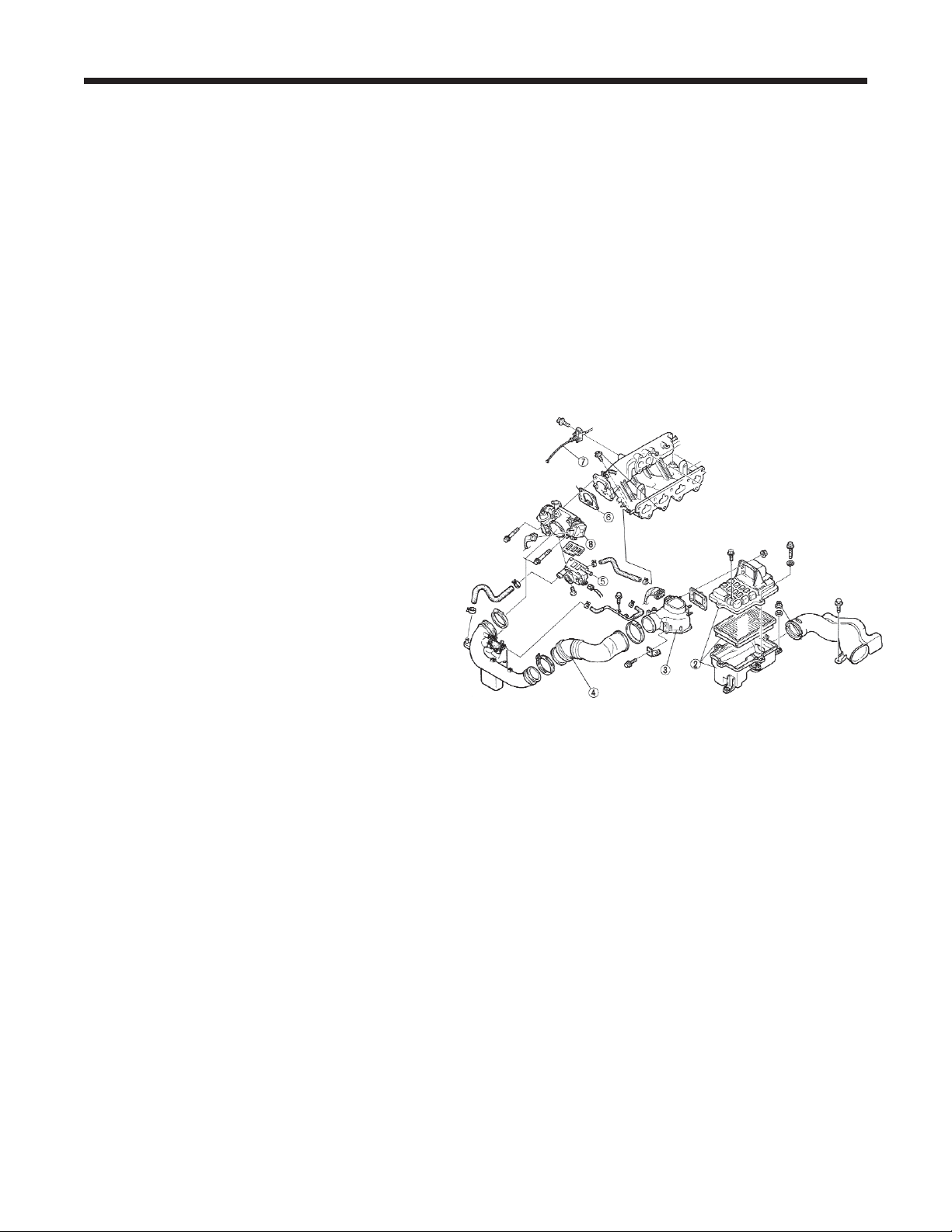
2. Stock Air Filter Box
3. Air Flow
4. Stock Plastic / Rubber Cross Over
5. ICS Valve (Idle Air Control)
6. Throttle Body Gasket
7. Throttle Cable
8. Throttle Body
Figure 1.3
Page 3
Keep the hose ends above the radiator cap
level to prevent leakage. Release the throttle
cable from the throttle shaft spool. Release the
Throttle Position Switch harness by lifting the
small wire clip that runs around the rectangular
base of the connector. If the throttle body gasket
tears as you remove it, you will need to clean
off the old gasket from both surfaces, the throttle body and the intake manifold. Carefully use a
knife or the backside of a hacksaw blade to
scrape the mounting surfaces clean. DO NOT
SCRATCH OR MAR THE MOUNTING SURFACES IN ANY WAY.
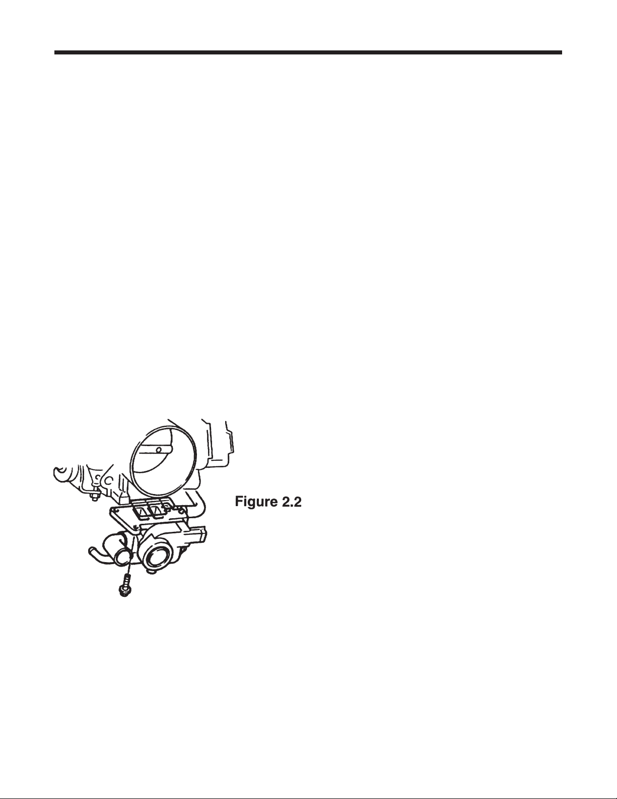
2.2 Moving to a worktable, remove the idle air
control (ICS) valve from the bottom of the throttle body by removing the three Phillips head
screws. Use a good quality screwdriver and be
careful not to strip the Phillips head screws. If
you cannot loosen a screw with the screwdriver,
use a small set of pliers from the side. Carefully
separate the two units making sure not to tear
the rubber gland gasket. The rubber gland gasket will want to stay with the Mazda throttle
body carefully pick it out with a flat blade screwdriver and save it for the next step.
2.3 Take the Idle Air Manifold (dummy throttle
body) from your supercharger kit and install the
Mazda idle air control valve (ICS) from step 2.2
in the appropriate place. Use the rubber gland
gasket from the Mazda throttle body in this position. Reuse the three Mazda Phillips screws.
Use no sealant, just the rubber gasket.
2.4 Install the Dummy Throttle Body and ICS
valve back onto the intake manifold in the same
position as the standard throttle body on the
intake manifold. Use the 1104 sealant provided
if the original gasket was not salvaged.
Reconnect the coolant hoses to the idle control
valve as you found them. Use hardware supplied as necessary.
2.5 Reconnect the idle control valve electrical
connector.
2.6 Take the Throttle Position Switch (TPS)
extension wire (4 conductor with sheathing)
from your kit and use it to extend your factory
TPS harness. We have provided six heat shrink
butt crimp connectors to use for each wire junction you will first have to cut the three pin connector off of the end of the Mazda TPS harness.
Cut at least 3 inches back from the end of the
plastic connector to give yourself enough room
to work with. Our extender has three colorcoded wires that match the colors of the Mazda
harness. The 4th (white) wire will not be needed. Strip a small section from each wire’s end
on the harness extender and connect it to the
appropriate color wire. Use the heat shrink butt
connectors to secure each splice. Crimp with an
appropriate tool or pliers. Use a heat gun or
similar to shrink the butt connector’s protective
tubing over the crimped connector. We do not
recommend the use of open flame to shrink the
tubing. Wrap the entire grouping of three connectors with electrical tape at both ends to protect from moisture and dirt.
2.7 Locate the ICS blanking plate and take it
over to your Mazda throttle body. You will use a
thin layer of sealant between the blanking plate
and the Mazda throttle body. Install this blanking
plate onto your Mazda throttle body using the
three Phillips head screws supplied in the kit.
Supercharger Installation Instructions
999-156, 999-157, 999-158 & 999-159 -3- Revised 06/08
Page 4
3.0 BELT DRIVES
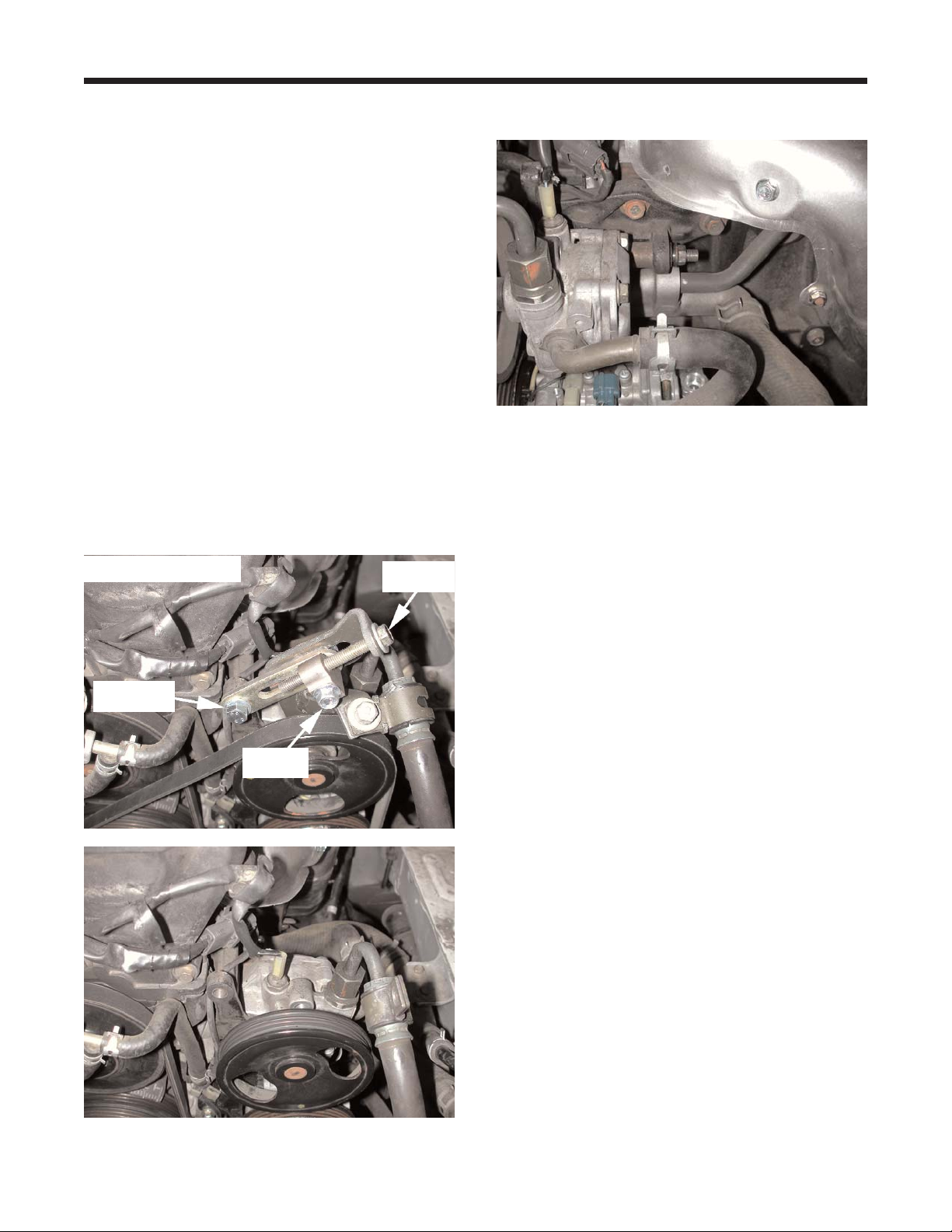
3.1 NOTE: CARS WITH POWER STEERING:
Use a 12mm socket and combination wrench to
loosen the power steering slide lock bolt. Then
loosen the tensioning bolt. Use a 14mm deep
socket and combination wrench to loosen the
power steering pivot bolt. You may have to rotate
the pulley to access this bolt. Using a 14mm
socket loosen and remove the slide anchor bolt
at the engine. At this point the power steering
pump should be able to pivot. Push the pump
downward towards the air conditioning compressor and remove the belt. Now, use a 12mm socket to remove the bolt securing the power steering
hose to the bracket. Using a 14mm socket,
remove the two bolts securing the power steering
bracket to the power steering pump. Remove the
whole tensioning system including the tensioning
and power steering brackets. Then, remove the
nut from the power steering pivot bolt. Illustration
3.1
3.2 Gather together the new belt tensioner
assembly, the new power steering hose support
bracket and the supercharger strap bracket.
Using a 22mm combination wrench slightly
loosen the power steering hose on the top of the
power steering pump and swing the hose to clear
the new power steering hose support bracket.
Then install the new hose support bracket in the
same place as the factory bracket. Temporarily
install the upper bolt to help with alignment.
Tighten the bottom bolt to 36 ft lbs. Once the bottom bolt is tight, remove the upper bolt. Now,
slide the power steering pivot bolt rearward out of
the pump. It will be reinstalled from the front.
Remove the rubber sleeve holding the shortheaded bolt in the new tensioner assembly. Slip
the new tensioner assembly into place behind the
power steering pulley, aligning its lower hole with
the pivot bolt hole. Reinstall the pivot bolt (from
the front). The bolt may come in contact with the
radiator cooling fan. It this occurs, the fan can be
depressed a slight amount to allow the bolt by or
use a 10 mm socket to remove the two bolts
securing the fan to the radiator and slide it up to
allow the bolt to be installed. Install the shortheaded bolt again just above the pivot bolt. It
should thread into the cast power steering bracket, bolted to the engine. Finally, install the last
bolt through the tensioner assembly and through
the power steering hose support bracket into the
upper hole in the pump. Slide the round hole of
the strap bracket onto the end of the pivot bolt on
the back side of the power steering pump and
start the flanged nut. Tighten the two upper bolts
on the tensioner assembly, securing it to the
power steering pump and the cast power steering
bracket, bolted to the engine. Tighten to 36 ft lbs.
The power steering pump pivot bolt will stay
loose until the supercharger is installed.
Supercharger Installation Instructions
999-156, 999-157, 999-158 & 999-159 -4- Revised 06/08
Illustration 3.1
Slide anchor
bolt
Slide lock
bolt
Tensioning
bolt
Page 5
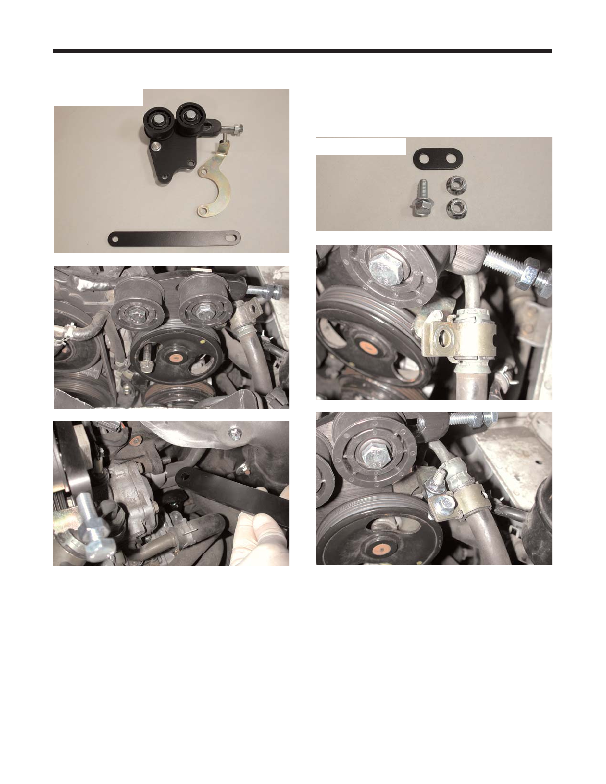
Illustration 3.2
3.3 Gather one M8 x 20mm flanged bolt, two M8
flange nuts and the power steering link. Bend the
tabs open on the power steering hose clamp,
using wire cutters. Open the clamp and slide it
down the hose. Make sure that the rubber slides
along with the clamp. Install the power steering
link over the stud on the power steering bracket
and start one of the flange nuts. Align the clamp
on the power steering hose with the remaining
hole in the power steering link. Slip the bolt
through the hole and start the nut. Once the bolts
are started, pull the hose away from the power
steering reservoir to gain clearance and tighten
the bolts to 18 ft lbs. Now tighten the hose on the
power steering pump. Once the two bolts are
tight, the two tabs on the power steering hose
clamp can be bent down again. Illustration 3.3
VERY IMPORTANT: Check the clearance
between the small coolant hose that runs from the
base of the thermostat housing and the passenger
side plastic idler pulley (see figure 8.1). If the
clearance is less than 1/2 inch between the hose
and the pulley, trim three quarters of an inch of
length off of the thermostat end of the small hose.
Reinstall the hose, reusing the spring clamp. By
removing a small piece of the hose end, the hose
will be pulled away from the idler pulley, avoiding
any damage during operation. This is a critical
area for attention since a hose failure could
Supercharger Installation Instructions
999-156, 999-157, 999-158 & 999-159 -5- Revised 06/08
Illustration 3.2
Illustration 3.3
Page 6
cause severe engine damage. Not all cars need
this modification.
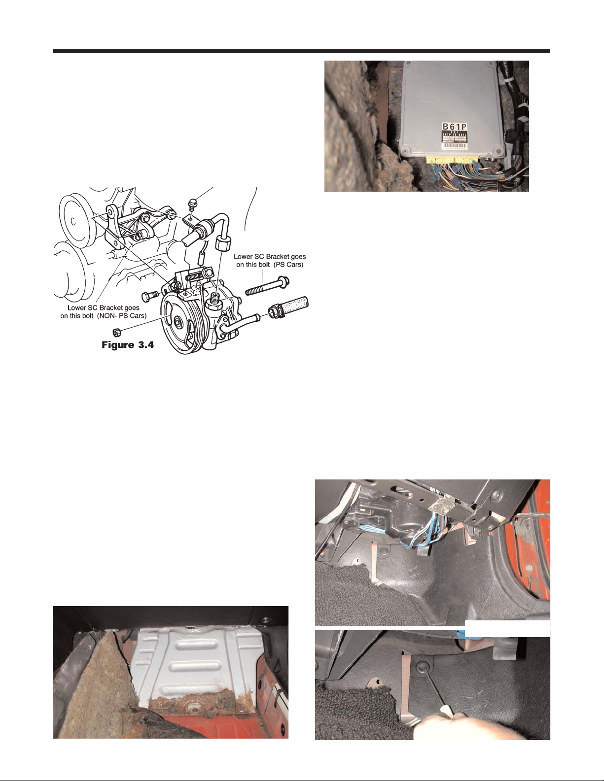
3.4 NON POWER STEERING CARS: Locate
your lower bracket assembly from the kit. The
end with the small 90-degree bracket mounts to
the idler bracket (standard on AC equipped cars)
or to new idler bracket (supplied with kit for nonAC, non-PS cars). Use the new, longer 10mm
bolt provided to attach this bracket to the engine
(Review figure 3.4 for bolt location).
4.0 POWERCARD
4.1 To access the ECU, remove the passenger’s
side kick panel trim by removing the plastic fastener securing the top, front portion of the panel.
Use a small screwdriver to pull out the center
section and then pull the whole fastener out.
There is also a push in fastener in the center of
the panel. Slip your fingers up behind the panel
and gently pull out on the center until it pops
free. Once the center fastener is free, slide the
panel out from under the door sill trim and set it
aside. Remove the forward two screws from the
door sill trim to allow easy removal and reinstallation of the carpet. Remove the floor mat and
pull back the carpet to expose a large metal
plate. Using a 10mm socket, remove the four
nuts and one bolt that secure the plate to the car.
Remove the plate to gain access to the
Electronic Control Unit (ECU). Illustration 4.1
4.2 Locate the PowerCard (Fuel Management
System) from your kit. We have included enough
wire to mount it on the center console or in the
glove box (recommended) and still reach the
passenger’s side footwell where the ECU is
located. Decide where you want to mount it,
route the wires from that location to the console
(or thru the glovebox area) back behind the
dashboard and down into the passenger’s side
footwell. Then cut the extra wire to length or
loop and wrap it with tape. Strip 1/4” of insulation
off of each of the PowerCard’s wires. Gather
together one (1) female spade connectors and
five (5) male spade connectors. Crimp the
female spade connector onto the Purple wire
and then crimp the male spade connectors onto
the rest of the wires. Slip the wires into the
included split loom. The split loom can be cut to
length as necessary. The Powercard will connect
to the ECU harness in the passenger (right hand)
foot well. We recommend routing the wires under
the dash or behind the center console on their
way to the footwell to keep them out of the driver’s way.
Supercharger Installation Instructions
999-156, 999-157, 999-158 & 999-159 -6- Revised 06/08
Illustration 4.2
Page 7

4.3 Locate the ECU’s fuel injector wires. Use
the pin-out on Pg17 of these instructions to help
you find the wrires. They are a large Yellow and
a large Yellow/Black wire located in the connector nearest the drivers side of the car. Use the
included T-taps and multi-purpose pliers to tap
into the wires. Next, locate a large Black wire in
the opposite end of that connector. T-tap the
Black wire. This is the system ground. Now, in
the far end of the other connector, locate the
White/Red wire and tap into it. This is switched
battery positive.
4.4 Next, locate the Red/Blue wire at the 2M
pin location in the same connector as the two
injector wires. This is the Exhaust Gas Oxygen
(O2) sensor wire. Cut this wire about 2” from the
ECU connector. Strip 1/4" of insulation from
both ends of the cut wire. Crimp a Male Spade
connector onto the side of the cut wire that
leads into the harness. Crimp a Female Spade
connector onto the side of the cut wire that
leads to the ECU connector. Connect the
Powercard’s Red wire to the T-tap on the
White/Red wire of the ECU and the
PowerCard’s Black wire to the T-tap on the
Black wire of the ECU. Connect the
White/Yellow & Green/Gray wires
of the PowerCard (between the power and
ground wires) to the T-taps on the Yellow and
Yellow/Black injector wires at the ECU. These
wires can be connected in any order. Connect
the Female spade connector on the Purple wire
of the PowerCard to the Male spade connector
on the Red/Blue wire leading into the harness.
Connect the Male spade connector on the
Purple/Yellow wire of the PowerCard to the
Female spade connector on the Red/Blue wire
leading into the ECU connector. Illustration 4.4
Supercharger Installation Instructions
999-156, 999-157, 999-158 & 999-159 -7- Revised 06/08
Illustration 4.3
Yellow &
Yel/Blk
Red/Blue
Illustration 4.4
Purple
Purple/Yellow
Page 8

4.5 Route the vacuum source from the engine
compartment to the Powercard. Start under the
hood and locate a free vacuum port on the intake
manifold (right hand side of the engine). If there
are no free ports, splice into an existing vacuum
source and use the included Tee to connect to
the hard plastic tubing included with the kit.
Route the tube from the intake manifold to the
firewall and across to the left side of the engine
compartment. The tubing will go through the
grommet with the wiring harness. Use a long
phillips screwdriver to push through the grommet.
Be cautious not to damage anything inside the
car. Remove the screwdriver and push a piece of
wire through the hole made by the screwdriver.
Wrap the wire around the tubing and secure with
electrical tape. Pull the tubing into the car using
the wire. Once inside the car, find a good way to
route the tubing across the car to the Powercard
location. Cut it to length if necessary and connect it to the silicone hose on the Powercard.
Illustration 4.5
4.6 The Powercard will mount in the glovebox or
on the dashboard. If it will be in the glovebox,
make sure that its wires don’t get stretched or
pinched in any of the glovebox hinges. The split
loom plastic sheathing from Step 4.1 will help
keep the wires located properly. For a dashboard
mount, you can put Velcro on the back of the
Powercard.
4.7 Reinstall the plate, the carpet, the kick panel
trim and the two screws from door sill trim.
5.0 SUPERCHARGER PREPARATION
5.1 Working on a table, set the supercharger unit
in a position easy to work with. Be very careful
not to bump the supercharger pulley in any way
as it can easily damage the front bearing. Check
outlet manifold for debris and clean it out if necessary. Install the outlet manifold as shown in figure 5.1. Get your Mazda throttle body with the
ICS blanking plate as installed in step #2.7 and
mount it to the supercharger using a thin film of
the sealant provided and the four bolts (8mm x
40) supplied in the kit.
5.2 Locate your throttle cable bracket that is bolted to your standard intake manifold and remove
the throttle cable by loosening the pinch nuts surrounding the cable end on either side of the
bracket. Once the nuts are loose, you can pull
the cable out of the bracket - the grommet will
deform and let you do this. Remove the throttle
cable bracket by removing the two 10mm head-
Supercharger Installation Instructions
999-156, 999-157, 999-158 & 999-159 -8- Revised 06/08
Illustration 4.5
Page 9

ed bolts. Unclip the throttle cable from the firewall anchors. Begin rerouting the throttle cable
by looping the end behind the brake master
cylinder and laying it along the driver’s side fender well.
5.3 Locate the black plastic Roto-mold inlet elbow
from your kit. Check elbow for debris and clean it
out if necessary. You will be placing the assembly
into the position shown prior to installing the
supercharger. Make sure to install the 2.5” to
2.75” reducer hose to the airflow meter end of
this plastic elbow prior to setting it in place. This
will greatly assist in airflow meter installation.
Also, install the 2.5” diameter hump hose to the
throttle body end of this plastic elbow. Use the
clamps provided to secure the hoses to the
elbow.
6.0 SUPERCHARGER INSTALLATION
6.1 Remove the engine lift eyelet at the front of
the engine, just above the exhaust manifold by
removing the bolt using a 14mm socket. Using
the two new flanged headed bolts supplied with
your kit, install these to the two bosses on the
side of your cylinder head. Leave at least 1/2” of
thread exposed on each bolt.
6.2 Bring the supercharger over to the engine.
Feed the throttle body end into the hump hose
already installed on the black plastic “air flow
meter to throttle body elbow” (make sure to slip a
fully opened hose clamp over the hose first).
Orient the supercharger so that you can slip the
large “keyholes” in the bracket attached to the
supercharger over the two bolt heads installed in
step #6.1. Make sure that the bolts move up their
respective vertical slots and seat against the
Supercharger Installation Instructions
999-156, 999-157, 999-158 & 999-159 -9- Revised 06/08
Figure 5.2
Page 10

upper edge of the horizontal slots in the bracket.
Slide the supercharger towards the firewall as far
as it will go. Tighten down the two pinch bolts
using an open-end wrench. If you find that the
bracket/supercharger assembly collides with your
cam cover vent tube during initial installation, it
means you did not leave enough threads
exposed on the two main mounting bolts
installed in step #6.1. Retry it with the bolts further out.
6.3 Swing the flat lower bracket up into place in
front of the supercharger boss. Locate the small
stamped throttle cable bracket from your kit and
thread the new bolt through the throttle cable
bracket hole, through the supercharger boss and
through the flat steel lower bracket. Secure with
the locking nut and bolt supplied. Make sure that
the head of the bolt is on the throttle bracket side
of the assembly. Leave the power steering pump
long bolt and nut finger tight (14mm heads).
6.4 Route your throttle cable so that it is looped
back toward the firewall, routing the cable just
behind the driver’s side headlamp motor. Install
the cable’s threaded end into the small bracket
attached to the underside of the supercharger.
Make certain that the cable/grommet is fully nested within the slot (this may require some muscle we made it tight so your throttle cable won’t ever
fall out). Open the throttle by hand and insert the
cable end into the throttle spool. Make sure that
the cable runs in the center of the groove of the
throttle spool. If it does not, adjust the throttle
cable bracket left or right until it is centered in the
spool’s groove. Have an assistant operate the gas
pedal multiple times to confirm that the action is
free and easy without binding or interference.
Make sure that the cable has a bit of “sloppy”
slack with the gas pedal released and that full
throttle is available when the gas pedal is fully
depressed. If it does not “flop” in the idle position,
you will have trouble setting your idle speed.
Make sure that the cable is run in such a way as
to allow for engine movement from side to
side.Make very certain that all throttle cablemounting points are secure - this installation area
is critical for safe operation of your car. This bracketry has been carefully designed for correct operation. It is your responsibility as the installer to
ensure that it is bolted together successfully without binding or interference.
7.0 AIRFLOW METER WORK
7.1 Locate the new air filter base from your kit and
install it to the air flow meter intake port, reusing the
Mazda cork gasket and four nuts. The air flow meter
is offset toward the top of the air filter base. The
seven pin electrical connector on the airflow meter
faces upward.
7.2 Locate the driver’s side shock tower support and
notice the Mazda air filter box mounting bracket
(painted body color) on the forward edge. This vertical bracket is held in place by a horizontal bolt (also
Supercharger Installation Instructions
999-156, 999-157, 999-158 & 999-159 -10- Revised 06/08
Page 11

painted body color). Remove the bolt using a 10mm
socket and store the bracket. On the “flying buttress” closest to the firewall, bend the captive nut
tang downward to make room for the plastic elbow
section using a small screwdriver in the hole.
7.3 Bring the air flow meter with the air filter base
installed over to the engine bay. Tilting the assembly at an angle, feed the air flow meter outlet into
the rubber reducer sleeve already in place on the
plastic elbow (install loose hose clamp first). The
air flow meter assembly fits into the space just
inside the shock tower, between the two “flying buttresses” of the shock tower. The extra hole and
boss in the air filter base will line up with the horizontal hole you just removed the 6mm body colored bolt from. Using the longer bolt provided (M6
x 30mm, Allen head), attach the air filter base/air
flow meter assembly to the car using this bolt (it
mounts horizontally, through the air filter base, the
flying buttress, and into the Mazda captive nut on
the flying buttress). Use thread-locking compound.
7.4 Make sure that there is no chaffing or rubbing
anywhere along the plastic elbow assembly, even
though it is a very tight fit. Gently reposition any
brake lines that are pressing against the elbow.
Make sure all joints and clamps are secure - a leak
in this area will keep your car from idling correctly.
However, never over tighten your clamps, they
may break somewhere down the road. Use the
small length of rubber hose (1/4” dia) that is slit
along its length to cover the brake line running just
above the elbow. This will prevent any contact at
this point, which may result in noise during operation.
7.5 Locate the 3/4” diameter idle air hose (5’
length) from your kit. Attach one end to the ‘large’
outside fitting on the plastic elbow downstream of
the airflow meter (just below the brake master
cylinder once the elbow is in place). Use a clamp
to secure the hose to the short 3/4” nipple. Run
the hose toward the front of the engine compartment, and across the engine side of the radiator.
Using the tie wraps provided, attach the rubber
hose securely to the radiator fan shroud supports
near the fan motor(s). Attach the end of the hose
to the idle control (ICS) valve nipple that is aimed
toward the front of the vehicle. Make sure that the
hose is attached in a way that will not interfere with
either fan operation or with the engine belts. At a
point along the length of the hose behind the radiator, cut it and install the check valve supplied.
Install the check valve with the flanged end toward
the plastic elbow using the small hose clamps. See
figure 7.6. The hose is supplied a bit longer than it
needs to be. Feel free to trim its length if you prefer. Be careful not to pinch the hose at any point doing so will affect your idle stability. You want to
have it tie-off in a low position; the cross over tube
will fit above this hose, hiding it in the final installation. On some cars, there might be a slight kink in
the hose where it attaches to the plastic elbow nipple. This is acceptable - orient the hose so it
remains open.
Supercharger Installation Instructions
999-156, 999-157, 999-158 & 999-159 -11- Revised 06/08
Figure 7.5
Page 12

7.6 Install the air filter element over the air filter
base. Next, collect the two studs and install them
with the element in place. Install the waffle-patterned air filter cap and secure using the nuts provided. Use the tie-wraps provided to secure all
components and keep them clear from the belt
runs, exhaust manifolds, and especially the throttle
cable. Reroute the air bag harness over the air filter, keeping it away from the headlight raising
motor. IMPORTANT! Secure the air bag harness
with tie wraps to keep it from falling into the engine
belt system or being pinched in any way.
7.7 Take the throttle body wiring harness extension
as left in step #2.6 and route the body of the harness along the firewall using the bright cad plated
firewall clips that originally held the throttle cable on
your stock Miata. Tie-wrap the extension harness
along the firewall in at least two places. Make sure
to leave enough slack on both ends to allow the
engine to rock side to side without pulling on the
harness. Contain any extra length in a neat fashion.
Connect the female end to the throttle body at the
throttle position sensor.
7.8 Find the internal restrictor taken out of your
PCV hose in step #1.4. Locate the 3/8” internal
diameter rubber hose from your kit and press the
restrictor into this hose at least one inch. Attach this
hose from the ‘medium’ size fitting on the plastic
intake elbow (near the throttle body, pointing to the
engine). Cut to length and attach the other end to
the camshaft cover fitting on the exhaust side.
Make sure the hose does not kink at any point and
that the restrictor is not left out. If you leave the
small restrictor out, the engine will not idle correctly.
7.9 Locate the 5/32” internal diameter idle balance
hose and attach it to the ‘small’ fitting on the plastic
elbow. Attach the other end to the unused vertical
vacuum nipple on the bypass block of the supercharger. Cut the line to the proper length, leaving
some slack to allow for engine movement. Make
sure the line is not pinched in any way and that it
has no possibility of interfering with the throttle
cable or spool. Use tie wraps as necessary to
secure the line. The diagram in figure #7.5 shows
the bypass actuator signal line being attached to
the engine side nipple on the bypass manifold. It
may be connected to the fender side nipple –either
is acceptable. Connect your idle balance line to
whichever vertical nipple is unused. The bypass
actuator may have two nipples on its “can”. The
upper one is used in this kit. The lower nipple
should be left open - it is used in the GM factory
installations.
7.10 Reconnect the 7 pin electrical connector to the
air flow meter. Make sure the harness is not
pinched at any point.
8.0 FINALASSEMBLY
8.1 Route the drive belt around the crank pulley,
over to the air conditioning compressor pulley (if
present, if not, route to the P/S pulley), up to the
power steering pump pulley, between the idler and
tensioner pulleys, over the supercharger pulley,
down between the idler and tensioner pulleys and
back to the crank. On some applications the belt
may have to be rolled on. If you find this to be the
case, install the belt on all the pulleys except for the
supercharger. Use an 18mm socket to turn the
supercharger pulley clockwise while guiding the belt
onto the pulley. Make sure the belt doesn’t come off
either of the idler pulleys. Do not use the engine’s
starter motor to roll the belt on. Tension the belt
using a 17mm socket on the tensioner bolt. Tighten
the bolt until there is 1/2" of deflection when you
press firmly on the belt between the idler and the
crank pulleys. Thread the jam nut on the tensioner
bolt down against the tensioner bracket. Use a
17mm combination wrench to lock the jam nut into
place. Torque the tensioner pulley bolt to 36 ft-lbs.
Also double check the torque on the fixed idler pulley bolt. If you hear belt squeal with the air conditioning on or when you turn the steering wheel, the
belt is not tight enough. Check the belt tension
again after 500 miles. Illustration 8.1
999-156, 999-157, 999-158 & 999-159 -12- Revised 06/08
Supercharger Installation Instructions
Page 13

NEVER A TTEMPT TO ADJUST THE BEL T WITH
THE ENGINE RUNNING! Retighten all bolts and
double-check your work.
8.2 Locate the rubber sleeves and the front cross
over tube. Check the inside of the cross over tube
for debris - clean if necessary. Running a rag
through the pipe pulled by a strong wire is a good
way to do this. Install the cross over tube between
the idle air manifold (dummy throttle body now on
the intake manifold) and the supercharger discharge manifold. If you find the rubber sleeves
hard to slip over their respective landings, use
some spray light oil such as WD40, which dries off
to lubricate the situation. Do not use gasoline products or pure silicone products. The best technique
for installing the cross over tube involves putting
the 2.75” diameter rubber sleeve on the supercharger manifold and the 2.5” diameter sleeve on
the cross over tube, and attach both with clamps.
Then install the cross over tube, starting at the
supercharger end first.
8.3 If you have cruise control, route the factory
vacuum line from the cruise control back to its original position, being careful to tie-wrap it away from
the engine belts or radiator fans. Remove the steel
spacer from one of the mounting grommets on
your stock Mazda air box. Use this 13/16” long
spacer and the 6mm x 25mm hex head bolt supplied to secure your cruise control brace to the air
filter base. The bolt will go vertically through the
cruise control leg brace and into the small ledge
with a threaded hole on the air filter base.
8.4 Once the cross over tube is installed correctly,
double-check all your pipe and tube connections.
There should be no loose ends or connections. Do
not over tighten any hose clamps, but ensure that
they are snug. Double check your supercharger
belt for correct tension. If the cross over tube is
pressing too hard against your upper radiator
hose, you can remove 3/4” to 1” from the radiator
end of the hose to allow for more clearance, if you
wish.
Complete step 8.5 before starting your engine.
8.5 CLEARANCES
IMPORTANT! MAKE SURE THAT YOU HAVE AT
LEAST 3/4” INCH CLEARANCE BETWEEN ANY
ENGINE MOUNTED COMPONENTAND ANY
BODY MOUNTED COMPONENT. CRITICAL
AREAS: BYPASS ACTUATOR TO BRAKE LINES
(VERY CRITICAL - The engine “rocks” strongly to
the driver’s side upon deceleration. If clearance is
too tight, your brake lines can be gently deformed
away from the super-charger bypass actuator by
hand. ) SUPERCHARGER OUTLET MANIFOLD
TO AIR FILTER (INCLUDING CLAMPS) ALL VACUUM LINES TO THROTTLE SPOOLAND CABLE
9.0 ENGINE ADJUSTMENTS
9.1 SUPERCHARGER BEL TDRIVE ADJUSTMENT
Start your engine and observe your belt drive. The
belt should line up with itself as it passes between
the two nylon idlers. To put it a different way, the
portion of the belt running up to the supercharger
should lay almost directly over the portion leaving
the supercharger and heading toward the power
steering pulley. If the upward run is more forward or
rearward than the downward run, you need to
move your supercharger slightly forward or backward with respect to the crankshaft pulley. You can
now access the two bolts attaching the supercharger’s bracket to the cylinder head from step 6.1 with
an open-end wrench. Loosen each bolt slightly to
allow for adjustment. Start the engine. You can now
move the supercharger assembly slightly forward or
rearward to correctly align the drive pulleys. The
slots in the Supercharger mounting bracket will
allow you to find the perfect alignment for the belt
run. NOTE: Do not attempt to move the supercharger with your hands with the engine running.
Use an appropriate tool. The best tool to use is a
flat blade screwdriver placed between the forward
bracket bolt and the front inside edge of the bracket. Move the supercharger assembly while watching the belt run the idler pulley. If you have the two
bracket bolts too loose, the supercharger will be out
of alignment from side to side. Make sure the two
bolts are snug enough to just allow some leveraged
movement. Once you have the belt running true in
999-156, 999-157, 999-158 & 999-159 -13- Revised 06/08
Supercharger Installation Instructions
Page 14

the center of the idler pulleys, tighten the rear bolt
to secure the position. Shut off the engine and tighten the other bracket bolt securely. Recheck all
mounting bolts for tightness.
9.2 POWERCARD ADJUSTMENT:
This is a CARB-legal supercharger kit. For CARBlegal compliance, your PowerCard has been preset
to CARB-legal settings. The three adjustment
modes that can still be accessed no longer adjust
the fuel settings. The tune is safe and conservative
and has been tested in cold, hot, mountain and
desert conditions. However, for trouble shooting
and testing the PowerCard prior to driving, follow
these procedures. Start your engine. The lights on
the PowerCard display will energize. With a proper
installation, you will see a sequence of lights run
from left to right and then a single green light at
position one. This single green light will flash every
two seconds when the engine is running but there
is no boost. If PowerCard doesn’t power up after 4
seconds double check your power and ground.
One or both are incorrectly hooked up. The single
green light may “flicker,” however a flashing green
and flashing red together indicate improper hookup
of the injector leads and PowerCard is not getting
an injector signal. If this happens, recheck installation of wiring to the injector leads. That said, when
decelerating it is possible to see the flashing green
and red together. This is perfectly normal as most
engine ECUs will shut off the injectors under
extended periods of deceleration. However, if you
get a flashing green and red at idle, PowerCard is
not seeing the injector signal and you must recheck
your installation. Make certain that the spade connectors are inserted properly into the square slot of
the t-tap, and not off to the side. If you can see the
silver spade connector through the translucent insulation, then you need to disconnect and properly
reconnect this connection.
9.2 IDLE ADJUSTMENT:
Restart your engine. Using the idle airscrew on
your throttle body (now on the back of the supercharger), adjust your idle speed to 950-rpm after
the engine is warm. This can best be approximated by closing the screw completely (turning clockwise) and backing it out one and a half turns
counter-clockwise. Adjust further to reach the
950-rpm value. Next, turn your headlights on
BRIGHT and put your heater fan on HIGH. Leave
the air conditioning off. Rev the engine briskly in
neutral to at least 2500 rpm and release. Notice if
the idle stops at 900 rpm. If it dips below this level
and feels like it will stall, then recovers to 950
rpm, open the idle airscrew (counterclockwise
rotation) one-eighth of a turn at a time until most
of this “droop” disappears. Aslight droop of 200
rpm or less is acceptable and normal. More than
that may create a stalling problem during driving.
Turn off the lights and heater fan and double
check that your idle speed is 950 rpm. If you
open the idle screw too much, you will create too
high of an idle speed when the lights and fan are
turned off. You also may possibly introduce a
stumble on part throttle to full throttle accelerations. In addition, a slow return to idle behavior
will occur.
9.3 If you have difficulty stabilizing the drooping
idle problem, adjust your dashpot to help in slowing the throttle’s closing. The factory specification
is that the dashpot tip just begins to touch the
throttle arm at 2500 rpm. Have an assistant hold
the engine at 2500 rpm from the driver’s seat.
The dashpot tip should just be touching the throttle arm. Adjust the dashpot so that this contact
point is at 3000 rpm or more to help with the
drooping idle. Your Miata will drive best with the
Supercharger Installation Instructions
999-156, 999-157, 999-158 & 999-159 -14- Revised 06/08
Page 15

lowest idle speed possible with only a slight
droop in the idle (checked as described above
with a warm engine, lights and heater fan on
high).
9.4 Using a timing light, adjust your ignition timing to 6 degrees before top dead center (BTDC).
You have to run a jumper wire (an unfolded
paper clip will do nicely) between terminals
“GND” and “TEN” of your diagnostics center
(located just above the driver’s side shock
absorber). The ignition timing is adjusted using
the position sensor mounted at the firewall end
of the intake camshaft. A 12mm box wrench will
loosen the securing bolt.
9.5 IGNITION TIMING AND FUEL QUALITY: Your
Miata supercharger kit is designed to operate on 91
Octane fuel. Make sure that you run your engine on
91 octane only, which means you should completely burn up any lower octane gas in your tank and
refill it with 91 octane before installing your supercharger kit. NOTE: In any case, should you ever
hear “pinging” or knocking from your engine when
under acceleration, you should take measures to
eliminate this detonation, i.e. higher-octane fuel or a
further retardation in ignition timing. NEVER CONTINUE TO OPERATE YOUR ENGINE IF YOU
HEAR ANYSIGNS OF DETONATION (PINGING
OR KNOCKING).
This kit has been carefully designed to work within
the stock Mazda engine parameters and no detonation will occur if the above settings and fuel are
followed. The only way detonation can creep into
your situation is if your engine has a mechanical
fault, the fuel you are using is of the incorrect
octane, if your timing is set incorrectly or if your
fuel filter is clogged. It is your responsibility as the
installer of this kit to ensure that the supercharger
has been installed according to specification.
DRIVING TIP:
If you should find yourself in a situation where you
cannot find high-octane fuel, you can bypass the
supercharger temporarily. Note the position the
bypass actuator arm is in during idle. This is the
position that bypasses the boost air back into the
supercharger inlet. As you blip the throttle, the
actuator arm will move and close a butterfly valve
inside the bypass manifold. Using a short piece of
wire, fix the bypass actuator arm in the “bypass”
position that it holds at idle. This will prevent boost
from being developed and thus, detonation will not
occur. Of course, your engine will now run like a
stock Miata, but will be quite operable for as long
as you need. When you find higher-octane fuel,
simply remove the wire to release the actuator arm
and the bypass will function normally, closing during acceleration, bypassing during idle and cruise.
Try to run the low octane fuel out of your tank
before filling up. Mixing fuels of different octane will
lower the overall rating and detonation could still
be a problem. You can order a Jackson Racing
Boost Timing Controller that retards your timing
during boosted conditions. This is useful for those
who can only find 91 Octane fuel or wish to
increase their low-end power by advancing the
static ignition timing.
9.6 Starting procedure: Start your engine as you
would a standard Miata. Remember to bring the
engine up to operating temperature (as indicated
by your water temperature gauge) before running it
hard. Full boost on a cold engine will greatly
increase your engine wear.
9.7 Oil changes: we suggest you use synthetic oil
such as Mobil 1 and change it regularly (5000
miles maximum). If you use a mineral oil, change it
every 2500 miles. While your supercharger does
not use any engine oil for its lubrication, your
engine will be working a little harder with the addition of a supercharger. The synthetic oil provides
an extra measure of protection, but is not necessary for safe and reliable operation.
9.8 Breaking-in: Your supercharger will work perfectly from the first time you fire it up. However, it
does need about 500 miles to fully seat the rotors.
Up to that time, you may notice a slight noise coming from the supercharger at idle. This is normal.
Supercharger Installation Instructions
999-156, 999-157, 999-158 & 999-159 -15- Revised 06/08
Figure 9.4
Page 16

9.9 Performance: You will notice that your engine
runs stronger on cold days than on very hot ones.
This is due to the nature of the internal combustion
engine. When the air is cold, the engine receives a
denser charge of air, thus more power can be produced. While this is true with any engine, the
supercharger amplifies this cold air benefit.
10.0 LONG TERM MAINTENANCE
10.1 BELTS
The only item to watch with your supercharger kit
will be the belt tension for the supercharger drive.
If you have a tension gauge for a poly-vee belt, the
tension is to be 90 pounds. If you see a large
accumulation of belt dust on your supercharger, it
is an indication that your belt is slipping. Aslight
amount of belt dust is normal. CHECKING YOUR
BELT FOR WEAR: As the belt wears, small cracks
will form in each of the ribs on the inside run of the
belt. Replace your belt when you can count six
cracks within in one inch of length (six cracks total
from all ribs combined).
10.2 DRIVEABILITY
If you notice a driveabilty problem as your car
ages, have your fuel pressure checked. Have a
technician install an accurate 0 to100psi fuel
pressure gauge in the fuel line BEFORE it enters
the fuel rail .
10.3 Every six months or so, check your hose
clamps for correct tension. The rubber hoses will
take a set and the clamps may not be holding as
tight. Also check all mounting bolts and nuts, particularly the throttle cable anchor bracket.
10.4 Your air filter is a long-life unit needing service only every 15,000 miles. To clean, you can
wash the filter element in soap and water. Use a
dish detergent soap such as Dawn, etc. Rinse
thoroughly and allow to dry. Wet the filter element
with a light application of ATF (automatic transmission fluid). Alternatively, a special cleaning kit
is available from Jackson Racing (#901-970).
10.5 At every oil change, lubricate the bypass
actuator arm contact point and shaft bushing with
light grease to insure long life - these parts are
exposed to under hood dirt and grime.
TROUBLESHOOTING
SYMPTOM: Engine cranks but will not start
PROBABLE CAUSES: Airflow meter disconnected; Idle air line open; Low battery voltage
CURE: Double check that seven pin to airflow
meter is well connected. Re-check the 3/4” ICS
line and the PCV line to see that they are not
leaking. Use a known good battery to “jump” the
Miata’s battery. It is possible to have enough voltage to crank a Miata but not enough to correctly
run the engine’s control computer.
SYMPTOM: Unstable Idle
PROBABLE CAUSE: Idle air screw set incorrectly; Restrictor left out in step #7.8; Pinched idle air
balance line; air leak in intake track.
CURE: Re-check restrictor. Check idle adjustment
procedure in step 8.1 above. Check the idle air
balance line for restriction or pinching. Check for
air leaks - vacuum at idle should be at least 17.7
in Hg.
11.0 FURTHER MODIFICATIONS
Now that your Miata has a stronger engine, there
are a few changes you might want to make to the
rest of the car to improve its performance. A free
flowing exhaust system will make your supercharged Miata that much faster.
Options include a 4-2-1 header (#903-110, CARB
approved, Manual Transmission only) and a catback exhaust system. Both are available at
MiataMania.com & Supercharger.com. Also, while
your new supercharger and the standard Mazda
clutch work well together, it is a good idea to step
up to the ACT Stage 1 clutch kit (#999-606) when
you change your clutch.
WARRANTY: The supercharger system carries a
two-year or 100,000 mile warranty (for the original
purchaser of the kit) against defects in materials
and workmanship. No other warranties apply. This
warranty is void if the subject vehicle is used in
any racing activities of any sort.
HELP: If you experience any problems with your
kit during installation or operation, contact your
retailer or Jackson Racing at 1-888-888-4079.
Supercharger Installation Instructions
999-156, 999-157, 999-158 & 999-159 -16- Revised 06/08
Page 17

Supercharger Installation Instructions
999-156, 999-157, 999-158 & 999-159 -17- Revised 06/08
90-93 Miata ECU Pin-Out Diagram
Left Side
Connector
ECU Yellow and Yellow/Black - Injectors
T-Tap these wires (White/Yellow &
Green/Gray PowerCard wires)
Ground
T-Tap this wire
ECU Red/Blue - Exhaust O2
Sensor - Cut this wire
and splice in PowerCard In/Out
(Purple & Purple/Yellow on
PowerCard)
12V Switched Power
T-Tap this wire
Power for PowerCard and
Timing Card
Right Side
Connector
Left Side
Connector
Right Side
Connector
 Loading...