

Jackson AJ-88 Parts Manual
AJ-44C Series Technical Manual 7610-001-76-22
Issued: 03-21-2006 Revised: N/A
SECTION 5: PARTS SECTION
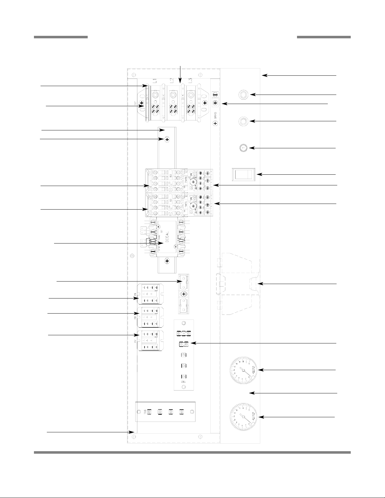
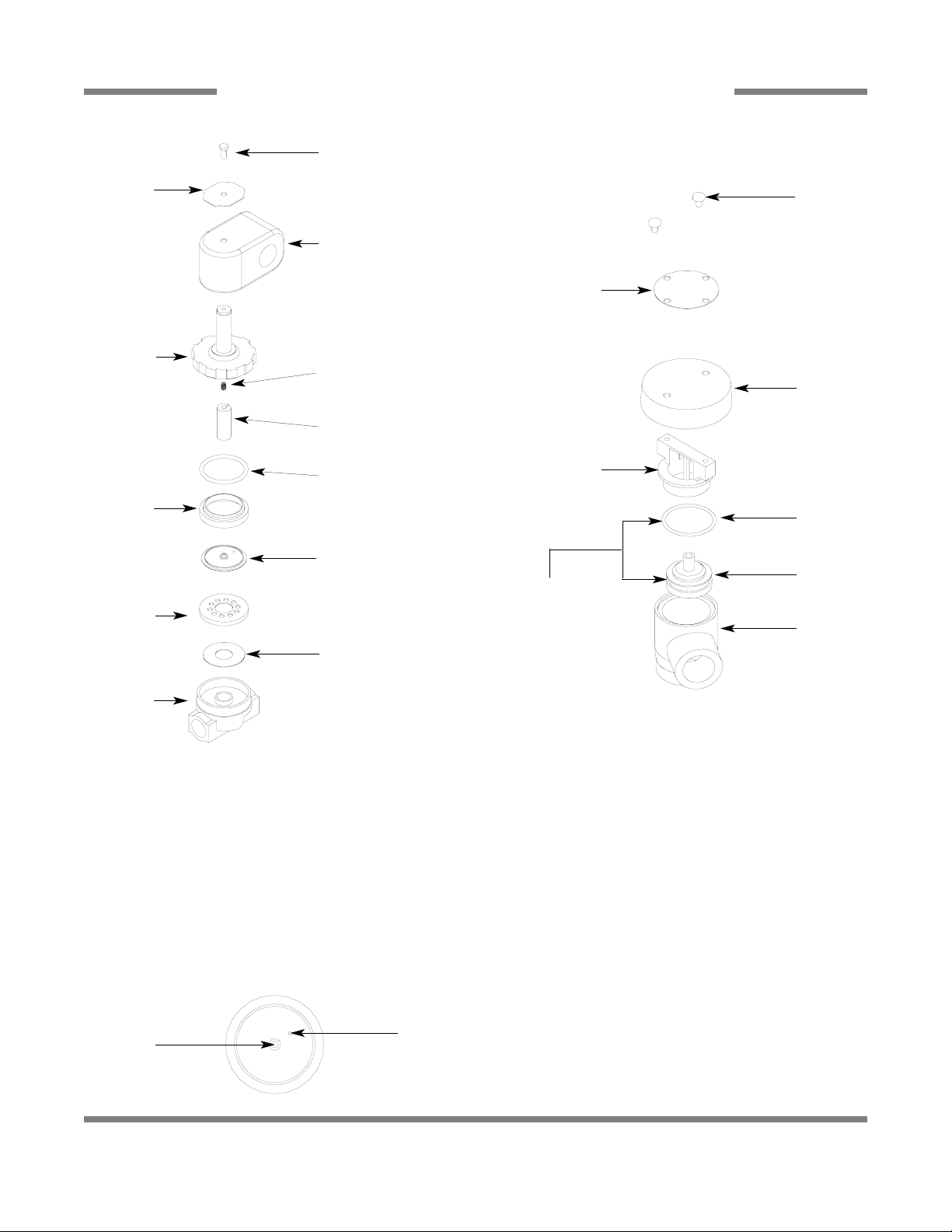
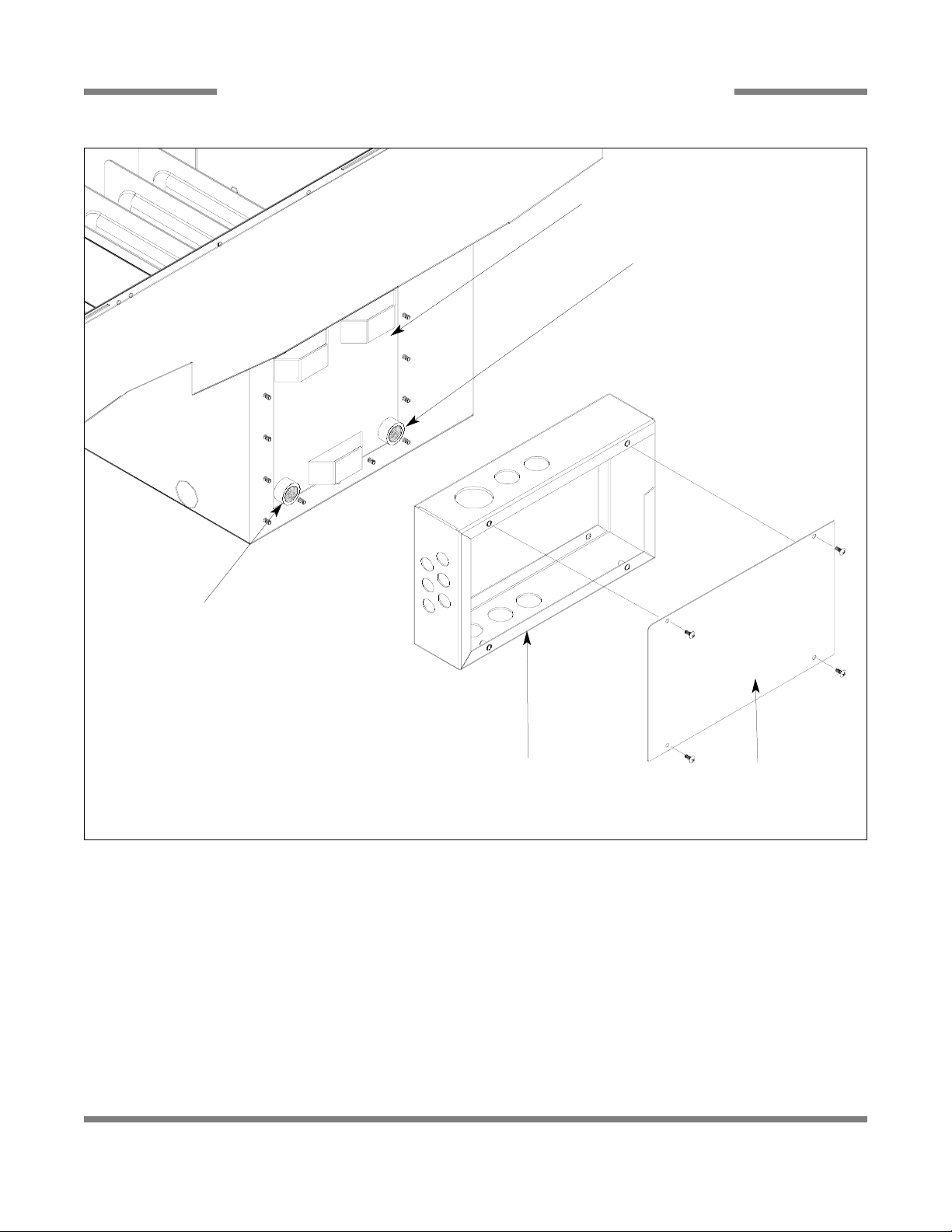
AJ-44 CONTROL BOX ASSEMBLY
62
1
2
4, 5
4, 8, 9, 10
11
12
13
14
15
10
16
17
17
4, 18, 29
19
20
21, 22
21, 22
21, 22
22, 23, 24
25, 26
22, 27
22, 28
7
6
3
PDF compression, OCR, web optimization using a watermarked evaluation copy of CVISION PDFCompressor

AJ-44C Series Technical Manual 7610-001-76-22
Issued: 03-21-2006 Revised: N/A
SECTION 5: PARTS SECTION
AJ-44 CONTROL BOX ASSEMBLY (CONTINUED)
63
ITEM QTY DESCRIPTION Mfg. No.
1 1 Electrical Box Weldment 05700-041-88-43
2 1 Terminal Block, 3 Pole 05940-011-48-27
3 1 Thermometer, 96” Lead 06685-111-68-49
4 6 Star Washer, External Tooth, 10-24 05311-273-02-00
5 6 Screw, 10-32 x 3/4” Long Phillips Trusshead 05305-011-62-17
6 1 Decal, Gauge 09905-021-72-29
7 1 Thermometer, 48” Lead 06685-111-68-48
8 1 Wire Lug, 2 AWG to 14 AWG 05940-200-76-00
9 1 Decal, Ground 09905-011-86-86
10 1 Screw, 10-32 x 1/2” Long Phillips Trusshead 05305-011-39-36
11 1 Decal, L1-L2-L3 09905-101-12-66
12 1 Light, Amber 05945-111-44-44
13 1 Light, Red 05945-111-44-45
14 1 Din Rail 05700-021-72-75
15 1 Circuit Breaker (200-380 Volt, 60 Hz Models Only) 5925-011-68-34
15 1 Circuit Breaker (CGP Models Only) 5925-111-64-18
16 1 Switch, ON/FILL - OFF/DRAIN 05930-301-46-00
17 2 Motor Contactor 05945-111-68-38
18 1 Heater Contactor 05700-011-71-44
19 1 Overload See Chart
20 1 Overload See Chart
21 3 Control Relay 05945-111-35-19
22 12 Screw, 6-32 x 3/8” Long Round Phillipshead 05305-171-02-00
23 1 Fuse (380 Volt-460 Volt, (all 60 Hz) Models Only) 5920-011-72-88
1 Fuse, 600 Volt Models Only 5920-002-75-95
24 1 Fuse Holder for (23) Above 5920-011-72-89
25 1 Transformer
200 Volt Model 05950-002-41-47
208-220-230-460 Volt Models 05950-011-68-35
208-220-230-460 Volt CGP Models 05950-002-46-10
380-415 Volt Models 05950-011-75-59
600 Volt Model 05950-002-23-77
26 4 Locknut, 10-24 with Nylon Insert 05310-373-01-00
27 1 Terminal Board 05940-002-78-97
28 1 Terminal Board 05940-021-89-41
29 3 Screw, 10-32 x 3/8” Long Phillips Trusshead 05305-173-12-00
30 2 Control Relay (CGP Models Only (Not Shown) 05945-111-72-51
MISCELLANEOUS PARTS NOT SHOWN:
Grommet, 1/2” OD x 3/8” ID 05325-011-46-73
Bushing, Heyco SB100 05975-210-09-00
Plug, Heyco 2700 G-875 05975-011-47-81
Control Box Cover 05700-031-66-88
Control Box Cover Hinge Weldment 05700-021-68-57
Control Hinge Rod 05700-011-68-58
Washer, Flat, S/S, 1/4” ID 05311-174-01-00
Cotter Pin 05315-011-68-56
MANUAL/DELIME Switch (located on rear of control box) 05930-301-22-18
MANUAL/DELIME Switch Decal (located on rear of control box) 09905-011-74-61
Copper Conductors Only Decal 09905-011-47-35
Control Box Leg 05700-011-71-47
Bolt, 1/4”-20 x 2-1/2” Long Hex Head 05306-011-83-52
Locknut, 1/4”-20 with Nylon Insert 05310-374-01-00
Component Mounting Plate (located inside the control box) 05700-031-67-03
Conduit Bracket 05700-021-70-88
PDF compression, OCR, web optimization using a watermarked evaluation copy of CVISION PDFCompressor
AJ-44C Series Technical Manual 7610-001-76-22
Issued: 03-21-2006 Revised: N/A
SECTION 5: PARTS SECTION
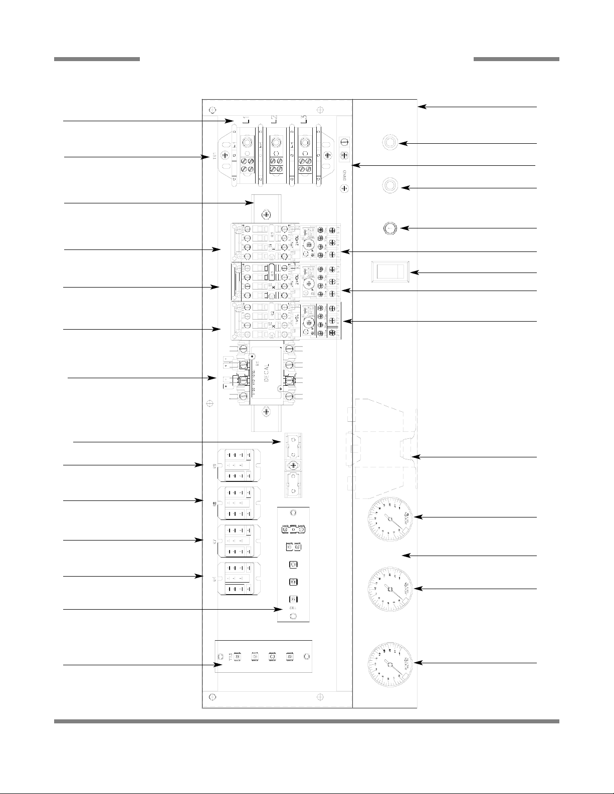
AJ-66 & AJ-80 CONTROL BOX ASSEMBLY
64
1
2
3
6
7, 12
8
9
14
14
14
15
16
17
18
19
20
22
24, 25
23
23
23
21
11
5
10
10
13
4
PDF compression, OCR, web optimization using a watermarked evaluation copy of CVISION PDFCompressor

AJ-44C Series Technical Manual 7610-001-76-22
Issued: 03-21-2006 Revised: N/A
SECTION 5: PARTS SECTION
AJ-66 & AJ-80 CONTROL BOX ASSEMBLY (CONTINUED)
65
ITEM QTY DESCRIPTION Mfg. No.
1 1 Electrical Box Weldment 05700-041-88-50
2 1 Decal, L1-L2-L3 09905-101-12-66
3 1 Terminal Block 05940-011-48-27
4 1 Terminal Board 05940-021-89-41
5 1 Decal, Gauge 09905-021-72-30
6 1 Light, Amber 05945-111-44-44
7 1 Wire Lug, 2 AWG to 14 AWG 05940-200-76-00
8 1 Light, Red 05945-111-44-45
9 1 Din Rail 05700-021-72-75
10 2 Thermometer, 96” Lead 06685-111-68-49
11 1 Thermometer, 48” Lead 06685-111-68-48
12 1 Decal, Ground 09905-011-86-86
13 1 Terminal Board 05940-002-78-97
14 3 Motor Contactor 05945-111-68-38
15 1 Circuit Breaker (200/208/230/360 Volt, 60 Hz Models Only) 5925-011-68-34
15 1 Circuit Breaker (CGP Models Only) 5925-111-64-18
16 1 Overload See Chart
17 1 Switch, ON/FILL & OFF/DRAIN 05930-301-46-00
18 1 Overload See Chart
19 1 Overload See Chart
20 1 Heater Contactor (for non-steam units) 05945-002-24-70
21 1 Relay 05945-111-72-51
22 1 Transformer (200 Volt Models Only) 05950-002-41-47
Transformer (208/220/230/460 Models Only) 05950-011-68-35
208-220-230-460 Volt CGP Models 05950-002-46-10
Transformer (380/415 Volt Models Only) 05950-011-75-59
Transformer (600 Volt Models Only) 05950-002-23-77
23 3 Control Relay 05945-111-35-19
24 1 Fuse Holder (380 (60 Hz)/460/600 Volt Models Only) 5920-011-72-89
25 1 Fuse (380 (60 Hz)/460 Volt Models Only) 5920-011-72-88
1 Fuse (600 Volt Models Only) 5920-002-75-95
26 2 Control Relay (CGP Models (Not Shown) 05945-111-72-51
MISCELLANEOUS PARTS NOT SHOWN:
Manual/Delime Switch 05930-301-22-18
Manual/Delime Switch Decal 09905-011-74-61
Decal, High Limit Warning Light 09905-002-49-48
Transformer, 150V, 60 Cycle 05950-011-68-35
Control Box Cover 05700-031-66-88
Control Box Leg 05700-011-71-47
Conduit Bracket 05700-021-70-88
PDF compression, OCR, web optimization using a watermarked evaluation copy of CVISION PDFCompressor

AJ-44C Series Technical Manual 7610-001-76-22
Issued: 03-21-2006 Revised: N/A
SECTION 5: PARTS SECTION
MOTOR OVERLOAD CHART
66
Model Volts Hz Phase Drive Motor Prewash Motor Wash Motor
AJ-44’S 208 50 3 05945-011-84-59 N/A 05945-111-68-40
220 50 3 05945-011-84-59 N/A 05945-111-68-40
230 50 3 05945-011-84-59 N/A 05945-111-68-40
380 50 3 05945-002-71-09 N/A 05945-111-68-40
415 50 3 05945-111-69-12 N/A 05945-111-81-33
440 50 3 05945-111-69-12 N/A 05945-111-81-33
208 60 1 N/A N/A N/A
230 60 1 N/A N/A N/A
200 60 3 05945-002-66-00 N/A 05945-002-65-99
208 60 3 05945-111-68-39 N/A 05945-111-68-40
230 60 3 05945-111-68-39 N/A 05945-111-68-40
380 60 3 05945-111-69-12 N/A 05945-111-81-33
460 60 3 05945-111-68-39 N/A 05945-111-68-40
600 60 3 05945-111-69-12 N/A 05945-111-81-33
AJ-66’S 200 50 3 05945-011-84-59 05945-002-65-98 05945-111-68-40
208 50 3 05945-011-84-59 05945-002-24-70 05945-111-68-40
220 50 3 05945-011-84-59 05945-002-24-70 05945-111-68-40
230 50 3 05945-011-84-59 05945-002-24-70 05945-111-68-40
380 50 3 05945-002-71-09 05945-002-24-70 05945-111-68-40
415 50 3 05945-111-69-12 05945-002-24-70 05945-111-81-33
440 50 3 05945-111-69-12 05945-002-24-70 05945-111-81-33
208 60 1 N/A N/A N/A
230 60 1 N/A N/A N/A
200 60 3 05945-002-66-00 05945-002-66-02 05945-002-65-99
208 60 3 05945-111-68-39 05945-111-68-41 05945-111-68-40
230 60 3 05945-111-68-39 05945-111-68-41 05945-111-68-40
380 60 3 05945-111-69-12 05945-002-24-70 05945-111-81-33
460 60 3 05945-111-68-39 05945-111-68-41 05945-111-68-40
600 60 3 05945-111-69-12 05945-111-81-33 05945-111-81-33
AJ-80’S 200 50 3 05945-011-84-59 05945-111-68-40 05945-111-68-40
208 50 3 05945-011-84-59 05945-111-68-40 05945-111-68-40
220 50 3 05945-011-84-59 05945-111-68-40 05945-111-68-40
230 50 3 05945-011-84-59 05945-111-68-40 05945-111-68-40
380 50 3 05945-002-71-09 05945-111-68-40 05945-111-68-40
415 50 3 05945-111-69-12 05945-111-81-33 05945-111-81-33
440 50 3 05945-111-69-12 05945-111-81-33 05945-111-81-33
208 60 1 N/A N/A N/A
230 60 1 N/A N/A N/A
200 60 3 05945-002-66-00 05945-002-65-99 05945-002-65-99
208 60 3 05945-111-68-39 05945-111-68-40 05945-111-68-40
230 60 3 05945-111-68-39 05945-111-68-40 05945-111-68-40
380 60 3 05945-111-69-12 05945-111-81-33 05945-111-81-33
460 60 3 05945-111-68-39 05945-111-68-40 05945-111-68-40
600 60 3 05945-111-69-12 05945-111-81-33 05945-111-81-33
PDF compression, OCR, web optimization using a watermarked evaluation copy of CVISION PDFCompressor
AJ-44C Series Technical Manual 7610-001-76-22
Issued: 03-21-2006 Revised: N/A
SECTION 5: PARTS SECTION
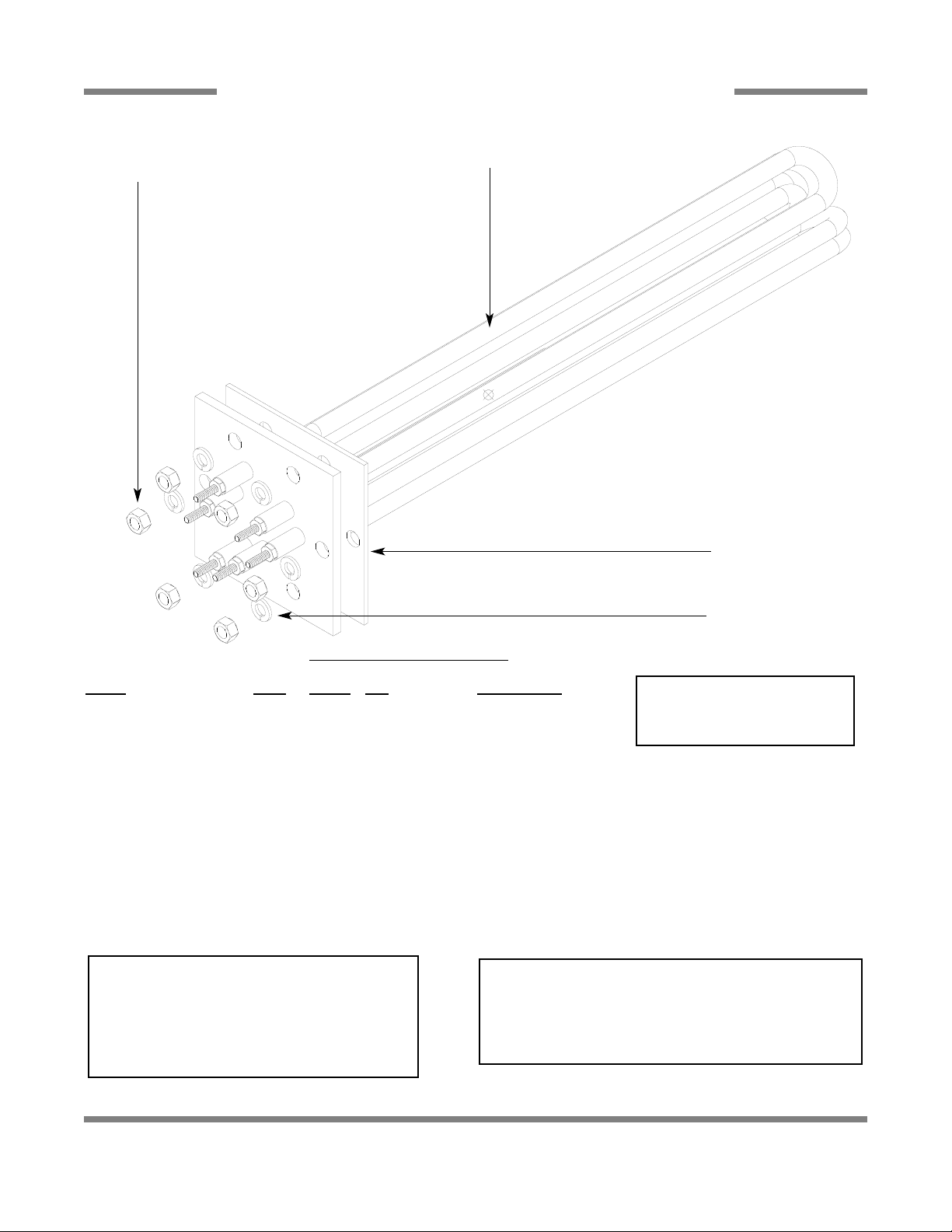
HEA TER ASSEMBLY
67
Heater Replacement Kit Chart
Model Volts Phase KW Part Number
All* 208 1 15 06401-003-10-21
230 1 15 06401-003-10-22
200 3 15 06401-003-10-21
208 3 15 06401-003-10-21
220 3 15 06401-003-10-22
230 3 15 06401-003-10-22
380 3 15 06401-003-10-28
415 3 15 06401-003-10-28
440 3 15 06401-003-10-29
460 3 15 06401-003-10-31
600 3 15 06401-003-10-33
* - AJ-44CGP, AJ-44CS, AJ-44CSL, AJ-66CGP, AJ-66CS, AJ-66CSL, AJ-80CS and AJ-80CSL models do not use electric
heaters in the wash tank.
See Heater Chart Below
Heater Gasket
05330-200-02-70
5/16” Lockwasher
5/16”-18 Hex Nut
Replacement Kit Note:
All heater kits come with the
heater, the gasket, lockwashers
and locknuts.
SERVICE NOTE:
When replacing the tub heaters, it is HIGHL Yrecommended that you also change out the gasket as well.
Once installed, gaskets become compressed and
are subjected to extreme temperature changes.
Replacing the gasket with a new one when replacing
the heater may prevent future leaks.
SERVICE NOTE:
The nuts used to secure the heater to the tub should be
torqued to 154 in-lbs. After tightening, the unit should be
allowed to heat up and operate normally for approximately 30
minutes. Secure power to the machine and check the nuts
once more to ensure that they are torqued to 154 in-lbs.
PDF compression, OCR, web optimization using a watermarked evaluation copy of CVISION PDFCompressor

AJ-44C Series Technical Manual 7610-001-76-22
Issued: 03-21-2006 Revised: N/A
SECTION 5: PARTS SECTION
HEA TER ASSEMBLY (CONTINUED)
68
The wash tank heater system is electrically connected in the circuit so that they are dependent upon the dishwasher being properly filled with and maintaining a safe water level, two thermostats (mounted in the heater box behind the dress panel), float
switch (mounted in the wash tank), and the heater relay (mounted in control box) with the heater being activated by the thermostats.
Once the dishwasher has been filled to the correct level, the heater should operate automatically. Should the tank heat be too
high, too low or no indication of temperatures at all, the following checkout should be made.
Note: The following checkout should be made by either a qualified service person or electrician.
A- Checkout of the heater system
1- If the temperature is too high, adjust thermostat using instructions on the page entitled “Thermostats”.
2- If temperature is too low, adjust thermostat as above, then:
a - Turn off power to machine by placing customer’s circuit breaker in the “OFF” position. Turn off machine
circuit breaker located on right side of control box.
b - Remove cover from control box on top of dishwasher.
c - Make sure water temperature is below 140° F.(preferably about 130°F.).
d - Turn on both circuit breakers. Observe heater relay (R1) while the power switch is turned “ON” and “OFF”.
If relay contacts move in and out, the heater relay is operating correctly: if not proceed to “C”.
B- If heater relay (R1) closes:
1 - Check power supply at incoming terminal board L1, L2 & L3 (3 phase only). It should be the same voltage as
indicated on the machine data plate.
2 - Check power at connections on heater relay (R1). The voltage should agree with the voltage on the
machine data plate. If not, check wires for breaks or bad connections.
3 - Check power at terminals of heater which should agree with the data plate. If not check wires for breaks or
bad connections.
4 - Temperatures should rise as explained in “C-1”, and amperage may be checked according to those instructions. Replace any defective elements.
C - If heater relay (R1) does not close.
1 - There is an insulated movable insulated movable bar on relay across the top. With an insulated probe, depress
this bar and observe the thermometer: the temperature should rise noticeably in a minute or two. If it moves slowly, it would indicate that the element is faulty. If it moves constantly higher at a good rate, elements should be
good.
Note: A check with an amp probe at heater relay (R1) terminals should be made to verify the amp draw on each leg.
This should be appropriate for the voltage and phase indicated on the data plate
HEATER PROTECTION & AUTOMATIC FILL
This control is activated when the power switch is turned “ON”. The primary function is to automatically energize the wash tank
heat circuit. It will also cutoff the wash tank heat circuit should the water be accidently drained from the machine with the power
switch still “ON”. The power switch should always be turned-off before draining the unit.
This water level control consists of two (2) floats that operate when the power switch is turned on and works in conjunction with
the thermostats and heater relays.
When the power switch is turned “ON” water starts to enter the dishmachine. When it reaches the proper level the normally
open contacts in the water level float switch close activating the heating circuit for tank heat.
If the water level below the correct level while power is still on, the float switch will sense the lack of water and de-activate the
heater.
PDF compression, OCR, web optimization using a watermarked evaluation copy of CVISION PDFCompressor

AJ-44C Series Technical Manual 7610-001-76-22
Issued: 03-21-2006 Revised: N/A
SECTION 5: PARTS SECTION
HEA TER ASSEMBLY (CONTINUED)/THERMOSTATS/DRESS P ANELS
69
THERMOSTATS
The thermostat range is from 140°F to 240°F with a maximum bulb exposure temperature of 300°F.
Calibration:
Wash Thermostat:
Set Point: 165°F (Adjustable range)
Hi-LImit Thermostat:
Fixed set point: 210°F (Non-adjustable)
The hi-limit thermostat is used to protect the heater element in the event of a run away regulating thermostat or a dry fire situ-
ation. It is set for 210°F +0°F or -10°F with a fixed set point. This part is not adjustable.
The wash tank regulating thermostat will maintain the correct wash water temperature to meet NSF requirements. These spec-
ify that the wash be no lower than 140°F on chemical sanitizing models and no lower than 160°F on hot water sanitizing
machines.
To order the thermostats and corresponding decals:
Kit, Thermostat Wash Regulating (CE/CELModels) 06401-003-18-20
Kit, Thermostat Wash Regulating (CS/CSLModels) 06401-003-18-21
Thermostat, High Limit Control 05930-011-49-43
HEATER BOX COMPONENTS
Heater Box Weldment 05700-031-66-81
Heater Box Cover 05700-031-66-82
Terminal Board 05940-002-78-97
FRONT DRESS P
ANELS
Model Left to Right Part Number Right to Left Part Number
AJ-44’s 05700-031-72-22 05700-031-72-22
AJ-44CGP 05700-002-52-77 05700-002-52-77
AJ-66’s 05700-031-71-85 05700-031-72-42
AJ-66CGP 05700-002-51-22 05700-002-57-84
AJ-80’s 05700-031-74-06 05700-031-77-10
PDF compression, OCR, web optimization using a watermarked evaluation copy of CVISION PDFCompressor
AJ-44C Series Technical Manual 7610-001-76-22
Issued: 03-21-2006 Revised: N/A
SECTION 5: PARTS SECTION
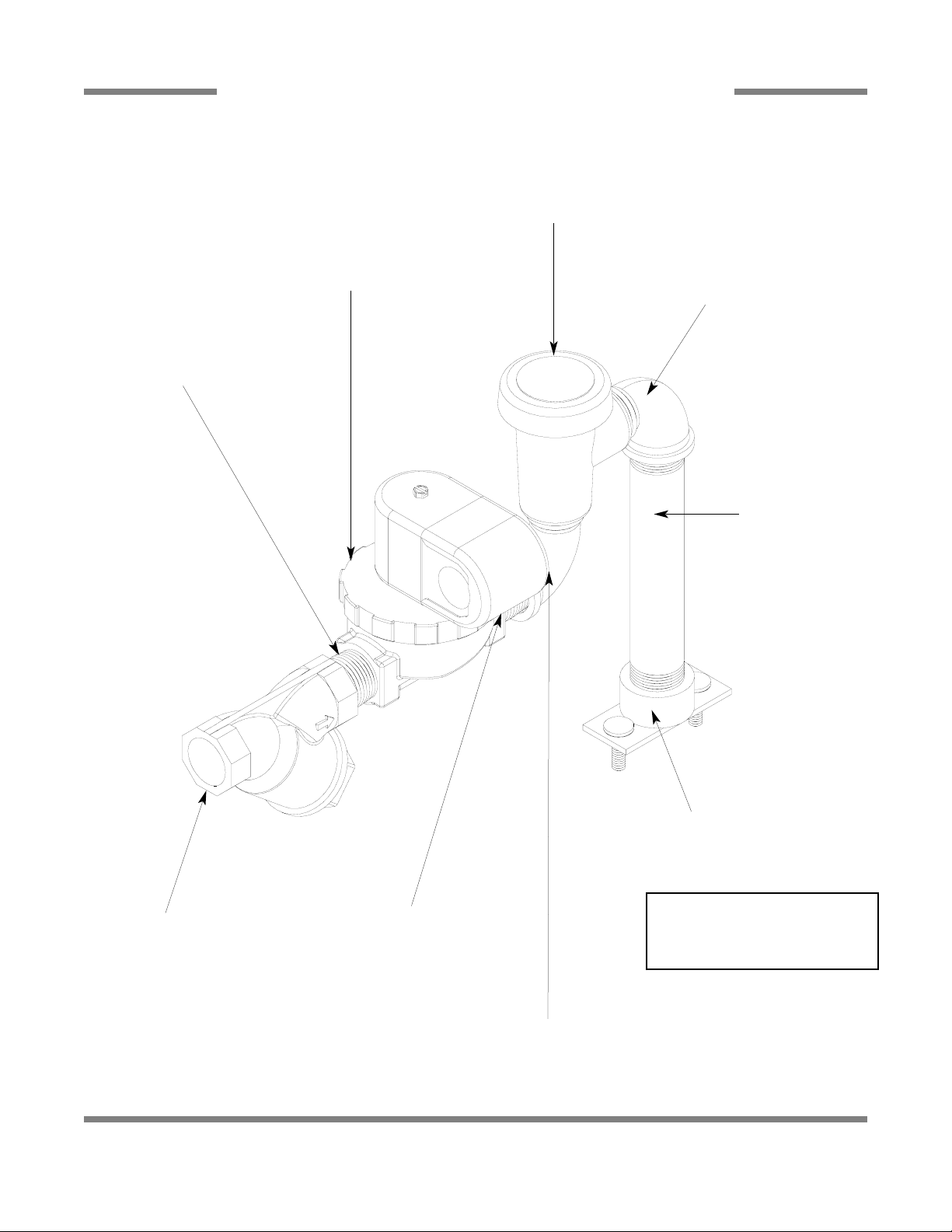
PREWASH PLUMBING ASSEMBLY
70
Y-Strainer, 3/4” NPT,
Brass
04730-717-02-06
Nipple, 3/4”, Brass, Close
04730-207-34-00
Valve, Solenoid, 3/4”
04810-100-53-00
Nipple, 3/4”, Brass, Close
04730-207-34-00
Vacuum Breaker, 3/4”
04820-002-53-77
Elbow, 90°, 3/4” Brass
04730-206-04-34
Elbow, 90°, 3/4” Brass
04730-206-04-34
Nipple, 3/4” x 6” Long
05700-001-26-74
Fill Line Injector Replacement Kit
06401-003-09-93
A new gasket can be
ordered using part number 05330-111-42-81.
Replacement Kit Note:
The kit for the fill line injector comes
with the injector weldment, a new
gasket and the mounting hardware.
PDF compression, OCR, web optimization using a watermarked evaluation copy of CVISION PDFCompressor
AJ-44C Series Technical Manual 7610-001-76-22
Issued: 03-21-2006 Revised: N/A
SECTION 5: PARTS SECTION
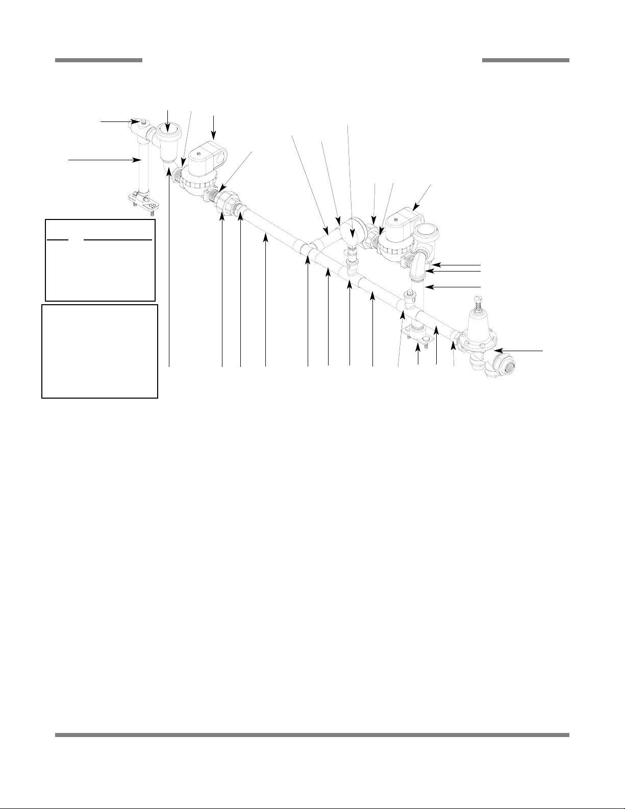
WASH SECTION INCOMING PLUMBING ASSEMBLY
71
ITEM QTY DESCRIPTION Mfg. No.
1 1 Rinse Injector Replacement Kit 06401-003-11-88
1 Gasket 05330-111-42-81
2 3 Plug, Brass, 1/8” NPT 04730-209-07-37
3 2 Vacuum Breaker, 3/4” NPT 04820-002-53-77
4 3 Elbow, Street, 3/4” NPT 04730-206-04-34
5 1 Plug 04730-209-01-00
6 2 Union, Brass, 3/4” 04730-212-05-00
7 2 Solenoid Valve, 3/4” 04810-100-53-00
8 4 Nipple, Close, Brass, 3/4” NPT 04730-207-34-00
9 2 Fitting, 3/4” Male to Slip Copper 04730-401-11-01
10 1 Tube, Copper See Chart
11 1 Fill Injector Replacement Kit 06401-003-09-93
1 Gasket 05330-111-42-81
12 1 Tube, Copper See Chart
13 1 Gauge, Pressure, 0-100 PSI 06685-111-88-34
14 1 Valve, Ball, Test Cock, 1/4” NPT 04810-011-72-67
15 1 Tube, Copper See Chart
16 2 Tee, 3/4” x 3/4” x 1/2” 04730-411-03-01
17 1 Elbow, Brass, 90°, 3/4” Copper 04730-406-42-01
18 2 Tube, Copper See Chart
19 1 Regulator, Pressure, 3/4” NPT, Brass 06685-011-58-22
20 1 Nipple, Brass, 6” Long 05700-001-26-74
21 1 Tee, 3/4”, CU x CU x CU 04730-411-46-01
22 2 Fitting, Adapter, 1/2” to 1/4” 04730-401-41-01
1
3
2
4
20
4
7
7
6 8
8
15
17
8
6 9
10 21 12 162218 5, 16
22
13, 14
19
11 18 9
Left to right direction shown
Tube Length Chart
Item Length (Inches)
10 3/4” x 3-7/16”
12 3/4” x 2-5/8”
15 3/4” x 3”
18 3/4” x 2-13/16”
Replacment Kits Notes:
The rinse and fill injector
replacement kits come with
the injectors, gasket and
mounting hardware. The
rinse injector kit (item 1)
also has the (3) required
brass plugs.
PDF compression, OCR, web optimization using a watermarked evaluation copy of CVISION PDFCompressor
AJ-44C Series Technical Manual 7610-001-76-22
Issued: 03-21-2006 Revised: N/A
SECTION 5: PARTS SECTION
EXTERNAL ELECTRIC BOOSTER INCOMING PLUMBING ASSEMBLIES
72
ITEM QTY DESCRIPTION Mfg. No.
1 - Y-Strainer, 3/4” NPT, Brass 04730-717-02-06
2 - Arrestor, Water Hammer, 1/2” NPT 06685-100-05-00
3 - Regulator, Pressure, 3/4” NPT, Brass 06685-011-58-22
4 - Nipple, 3/4” NPT x 2” Long, Brass 04730-207-46-00
5 - Elbow, Brass, 90°, 3/4” 04730-206-13-00
6 - Nipple, 3/4” NPT, Close, Brass 04730-207-34-00
7 - Coupling, 3/4” FNPT x 3/4” FNPT, Brass 04730-011-87-95
8 - Adapter, 3/4” Male 04730-401-11-01
9 - Tube, Copper See Chart
10 - Adapter, 1/2” NPT x Male 04730-401-07-01
11 - Tee, Copper, 3/4” x 3/4” x 1/2” 04730-411-03-01
1
8
9
11
9
8
2
10
3
4
5
6
7
1
3
4
7
5
6
Plumbing with Water Hammer Arrestor
Plumbing without Water Hammer Arrestor
6
Tube Length Chart
Item #
Length (Inches)
9 3/4” x 3-7/16”
PDF compression, OCR, web optimization using a watermarked evaluation copy of CVISION PDFCompressor
AJ-44C Series Technical Manual 7610-001-76-22
Issued: 03-21-2006 Revised: N/A
SECTION 5: PARTS SECTION
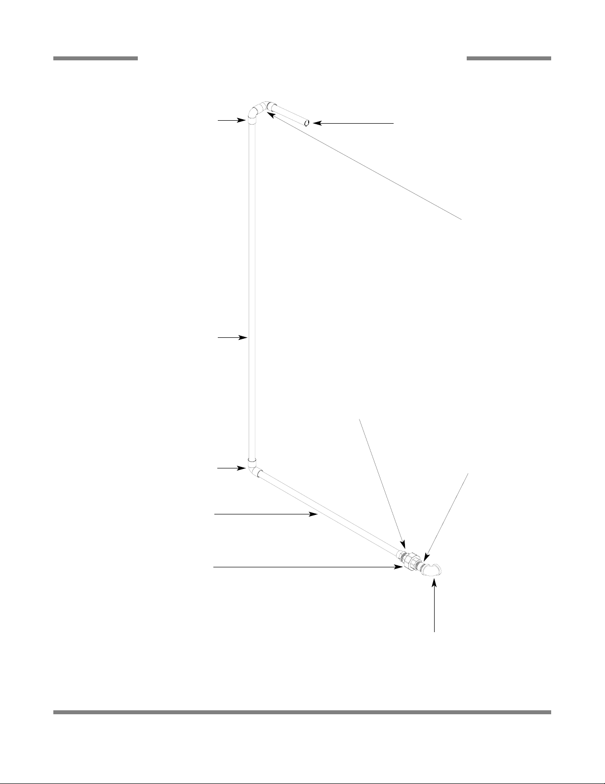
EXTERNAL ELECTRIC BOOSTER OPTION OUTLET PLUMBING
73
Elbow, Brass, 90°, 3/4”
04730-206-13-00
Nipple, 3/4” NPT x 2” Long, Brass
04730-207-46-00
Union, 3/4” NPT, Brass
04730-212-05-00
Adapter, 3/4”, Brass
04730-401-11-01
Tube, Copper, 3/4” x 24” Long
Elbow, 3/4” Copper to Copper (Female)
04730-406-16-01
Tube, Copper, 3/4” x 49-1/2” Long
Elbow, 3/4” Copper to Copper (Female)
04730-406-16-01
Elbow, 3/4”, 90°, Street, Copper to Copper
04730-406-40-01
Tube, Copper, 3/4” x 5-7/8” Long
PDF compression, OCR, web optimization using a watermarked evaluation copy of CVISION PDFCompressor
AJ-44C Series Technical Manual 7610-001-76-22
Issued: 03-21-2006 Revised: N/A
SECTION 5: PARTS SECTION
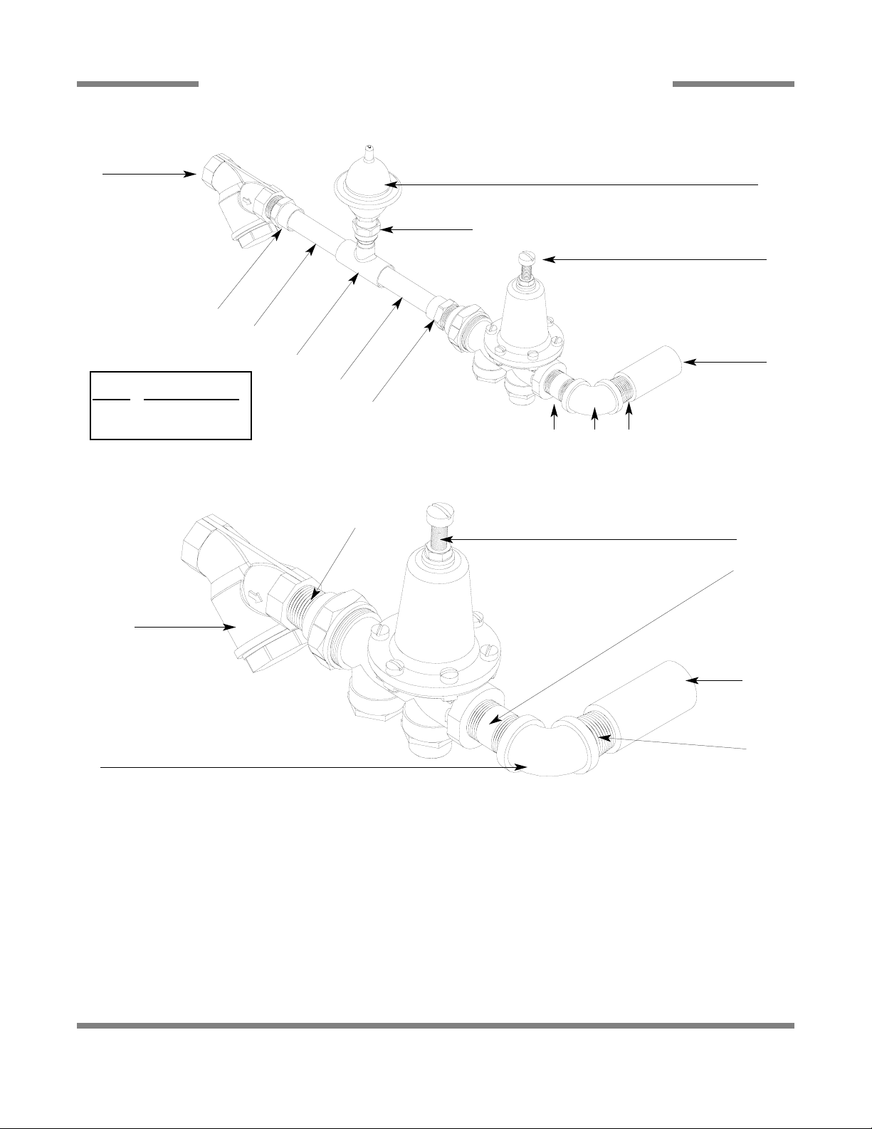
WATER HAMMER ARRESTOR OPTION/WATER PRESSURE REGULATOR KIT OPTION
74
Nipple, 3/4” NPT,
Close, Brass
04730-207-34-00
Water Arrestor, 1/2” NPT
06685-100-05-00
Tee, 3/4” x 3/4” x 1/2”
04730-211-06-00
Water Arrestor, 1/2” NPT
06685-100-05-00
Bushing, 3/4” x 1/2”
04730-002-01-34
Tee, Brass, 3/4” x 3/4” x 3/4”
04730-211-01-34
Nipple, Close, 3/4”
04730-207-34-00
Regulator, Pressure, 3/4”
06685-011-58-22
WATER PRESSURE REGULATOR WITH ARRESTOR KIT OPTION
WATER HAMMER ARRESTOR OPTION
PDF compression, OCR, web optimization using a watermarked evaluation copy of CVISION PDFCompressor
AJ-44C Series Technical Manual 7610-001-76-22
Issued: 03-21-2006 Revised: N/A
SECTION 5: PARTS SECTION
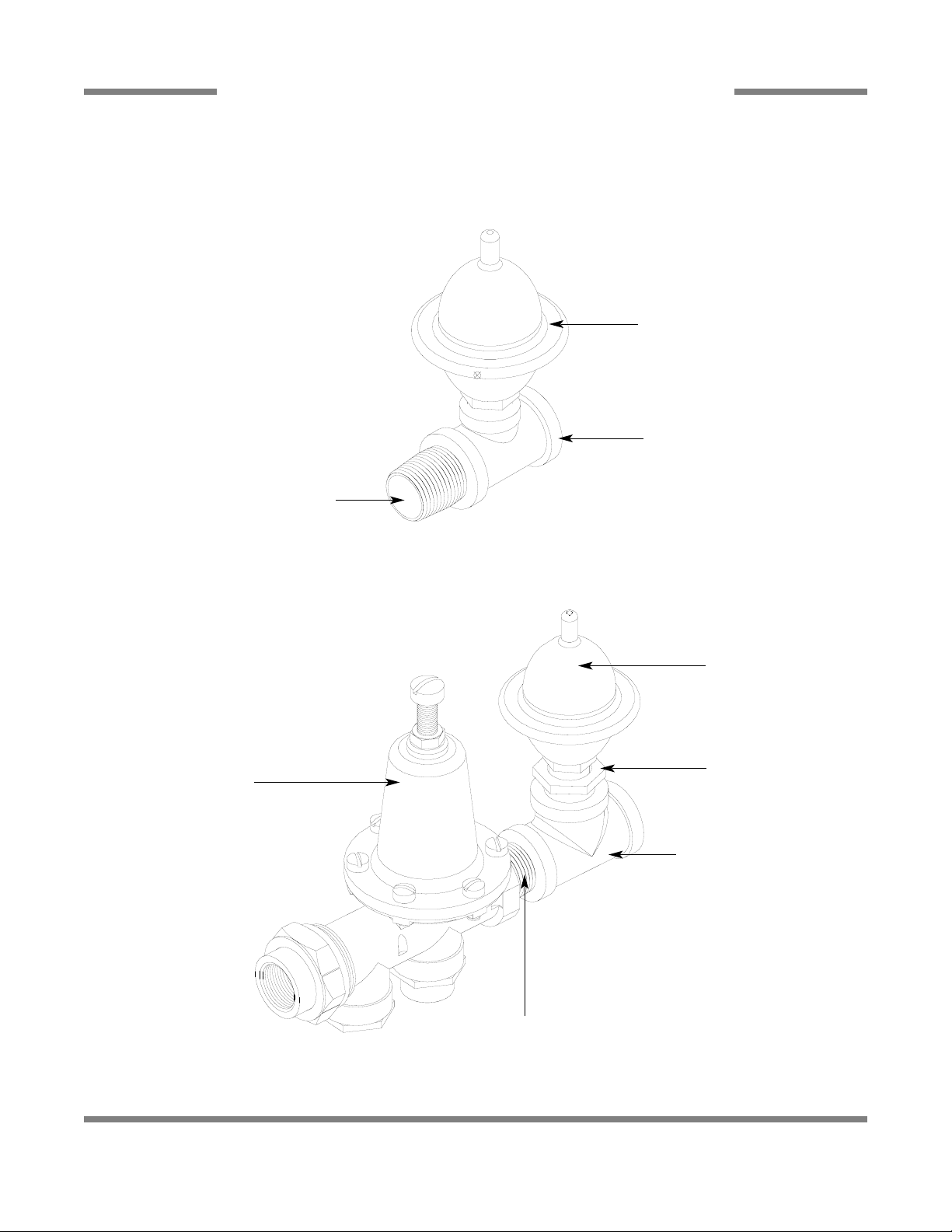
RINSE SOLENOID VALVE & VACUUM BREAKER REPAIR PARTS KITS
75
Complete 110 Volt Solenoid Valve Assembly, 3/4”
04810-100-53-00
Coil & Housing only, 3/4”
06401-003-07-43
Possible Problems:
1. Pilot port extension #1 clogged. Clean hole.
2. Hole #2 Clogged. Pass heated straight pin through hole.
DISASSEMBLY - These valves may be taken apart by
unscrewing the bonnet and the enclosing tube assembly from
the valve body assembly . After unscrewing, carefully lift off the
bonnet and enclosing tube assembly. Don’t drop the plunger.
The o-ring seal and diaphragm cartridge can now be lifted out.
Be careful not to damage the machined faces while the valve
is apart.
TO REASSEMBLE - Place the diaphragm cartridge in the
body with the pilot port extension UP. Hold the plunger with
the synthetic seat against the pilot port. Make sure the o-ring
is in place, then lower the bonnet and enclosing tube assembly over the plunger. Screw the bonnet assembly snugly down
on the body assembly.
Screw
Data Plate
Coil & Housing
Valve Bonnet
Spring
06401-003-07-40
Plunger
06401-003-07-40
Spring position is moved
for clarity.
Goes below the plunger.
O-Ring
06401-003-07-42
Diaphragm
Retainer
Diaphragm
06401-003-07-42
Screen
Retainer
Mesh Screen
Valve Body
Components of
Repair Kit
04820-001-60-57
Cap Screw
Data Plate
Cap
O-Ring
Plunger
Body
Cap Retainer
1
2
Complete Vacuum Breaker Assembly, 3/4” NPT
04820-002-53-77
PDF compression, OCR, web optimization using a watermarked evaluation copy of CVISION PDFCompressor
AJ-44C Series Technical Manual 7610-001-76-22
Issued: 03-21-2006 Revised: N/A
SECTION 5: PARTS SECTION
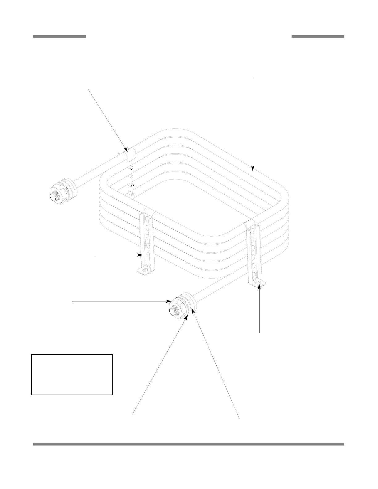
STEAM UNIT WASH TANK COIL ASSEMBLY
76
Coil Weldment
05700-002-84-03
Stand “C” Weldment
05700-002-74-84
Stand “D” Weldment
05700-002-74-85
Coil Nut
05310-011-17-85
Flat Washer
05700-001-17-87
Coil Gasket
05700-001-17-86
SERVICE NOTE: Jackson
HIGHLY recommends that the
Coil Gaskets be replaced any
time the Coil Weldment is
replaced or removed for an
extended period of time.
Stand “B” Weldment
05700-002-74-83
PDF compression, OCR, web optimization using a watermarked evaluation copy of CVISION PDFCompressor
AJ-44C Series Technical Manual 7610-001-76-22
Issued: 03-21-2006 Revised: N/A
SECTION 5: PARTS SECTION
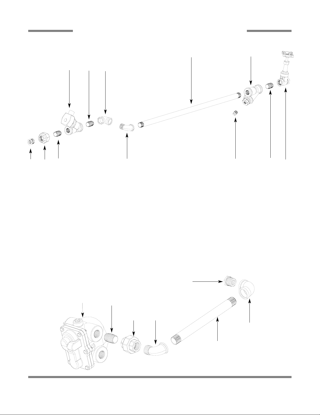
STEAM PLUMBING (LEFT TO RIGHT)
77
ITEM QTY DESCRIPTION Mfg. No.
1 1 Reducer, 3/4” NPT to 1/2” NPT, Black Iron 04730-911-02-34
2 1 Union, 3/4” NPT, Black Iron 04730-912-01-00
3 3 Nipple, Close, 3/4” NPT, Black Iron 04730-907-01-00
4 1 Valve, Steam Solenoid, 3/4” NPT, 120V 04820-011-87-39
5 1 Elbow, 90°, 3/4” FNPT, Black Iron 04730-906-10-34
6 1 Elbow, Street, 90°, 3/4” NPT, Black Iron 04730-011-87-37
7 1 Y-Strainer, 3/4” NPT, Black Iron 04730-217-01-32
8 1 Valve, Gate, Steam, 3/4” NPT 04820-100-19-00
9 1 Plug, 3/8” NPT, Black Iron 04730-909-02-34
10 1 Nipple, 3/4” NPT x 32” Long 04730-002-21-27
11 1 Reducer, 3/4” NPT to 1/2” NPT, Black Iron 04730-911-02-34
12 1 Elbow, 90°, 3/4” FNPT, Black Iron 04730-906-10-34
13 1 Elbow, Street, 3/4” NPT, Black Iron 04730-011-87-37
14 1 Union, 3/4” NPT, Black Iron 04730-912-01-00
15 1 Nipple, Close, 3/4” NPT, Black Iron 04730-907-01-00
16 1 Steam Trap, 3/4” NPT 06680-500-02-77
17 1 Pipe, 3/4” NPT x 10” Long, Black Iron 04730-907-06-34
1
2
3 6
4
3 5
10
9
7
3
8
11
12
17
1314
15
16
STEAM INLET PLUMBING
STEAM OUTLET PLUMBING
PDF compression, OCR, web optimization using a watermarked evaluation copy of CVISION PDFCompressor
AJ-44C Series Technical Manual 7610-001-76-22
Issued: 03-21-2006 Revised: N/A
SECTION 5: PARTS SECTION
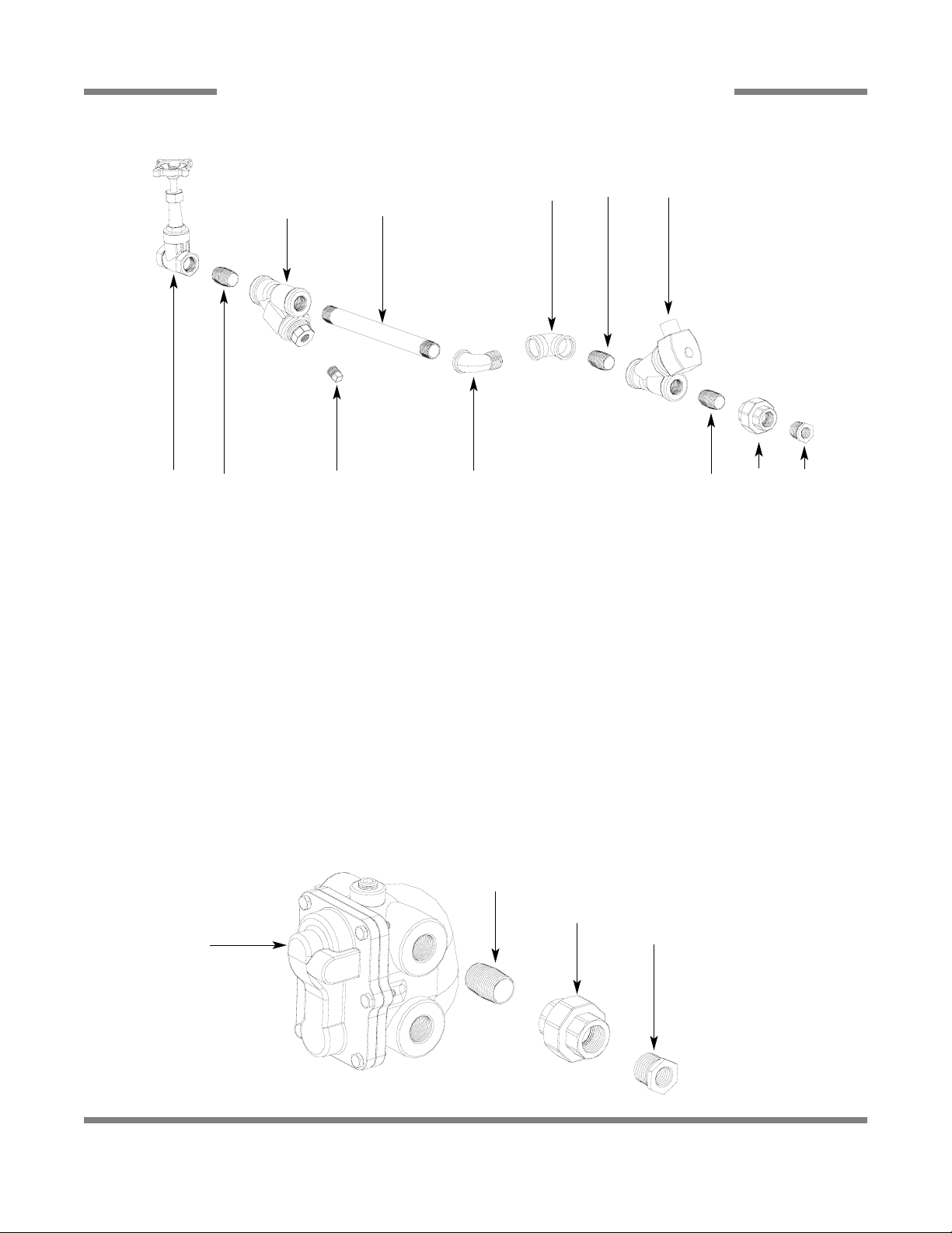
STEAM PLUMBING (RIGHT TO LEFT)
78
ITEM QTY DESCRIPTION Mfg. No.
1 1 Reducer, 3/4” NPT to 1/2” NPT, Black Iron 04730-911-02-34
2 1 Union, 3/4” NPT, Black Iron 04730-912-01-00
3 3 Nipple, Close, 3/4” NPT, Black Iron 04730-907-01-00
4 1 Valve, Steam Solenoid, 3/4” NPT, 120V 04820-011-87-39
5 1 Elbow, 90°, 3/4” FNPT, Black Iron 04730-906-10-34
6 1 Elbow, Street, 90°, 3/4” NPT, Black Iron 04730-011-87-37
7 1 Y-Strainer, 3/4” NPT, Black Iron 04730-217-01-32
8 1 Valve, Gate, Steam, 3/4” NPT 04820-100-19-00
9 1 Plug, 3/8” NPT, Black Iron 04730-909-02-34
10 1 Nipple, 3/4” NPT x 10” Long 04730-907-06-34
11 1 Reducer, 3/4” NPT to 1/2” NPT, Black Iron 04730-911-02-34
12 1 Elbow, 90°, 3/4” FNPT, Black Iron 04730-906-10-34
13 1 Elbow, Street, 3/4” NPT, Black Iron 04730-011-87-37
14 1 Union, 3/4” NPT, Black Iron 04730-912-01-00
15 1 Nipple, Close, 3/4” NPT, Black Iron 04730-907-01-00
16 1 Steam Trap, 3/4” NPT 06680-500-02-77
17 1 Pipe, 3/4” NPT x 10” Long, Black Iron 04730-907-06-34
8 9 63
7
10
5 3
3
4
1
2
17
13
14
16
STEAM INLET PLUMBING
STEAM OUTLET PLUMBING
PDF compression, OCR, web optimization using a watermarked evaluation copy of CVISION PDFCompressor
AJ-44C Series Technical Manual 7610-001-76-22
Issued: 03-21-2006 Revised: N/A
SECTION 5: PARTS SECTION
GAS COIL ASSEMBLY (CGP MODELS)
79
Other items used but not shown.
ITEM QTY DESCRIPTION Mfg. No.
1 1 Thermostat, High Limit 05930-011-49-43
2 1 Terminal Board 05940-002-78-97
3 1 Thermostat Bracket 05700-011-81-64
4 1 Decal, Thermostat Regulating 09905-011-84-31
5 1 Thermostat, Wash Regulating 06401-140-00-32
6 2 Fitting, 1/4”, Imperial Brass 05310-924-02-05
Gas Coil Weldment
05700-002-44-23
Connection point for:
Hose, Recirculating Discharge
(See “Hose Connections” page )
Connects with:
3/4” 90° Elbow Brass
04730-206-13-00
3/4” Close Brass Nipple
04730-207-34-00
Connection point for:
Hose, Wash Coil Assembly
(See “Hose Connections” page )
Connects with:
3/4” 90° Elbow Brass
04730-206-13-00
3/4” Close Brass Nipple
04730-207-34-00
Coil Box Weldment
05700-002-50-94
Gas Coil Box Cover
Replacement Kit
06401-003-10-37
PDF compression, OCR, web optimization using a watermarked evaluation copy of CVISION PDFCompressor
 Loading...