


否则可能触电
Warning: For your personal safety, when operating the kind of products, please make sure that the ground wire of power plug is connected to ground, otherwise an electric shock may occur.
 Safety instruction:
1. 查阅。
Before installing and using this kind of products, please read user manual very carefully, and take good care of this manual for temporary reference.
2.
All instruction with marks  must be carried out, otherwise body injury or equipment damege may occur.
This kind of products must be installed and operated by correctly and professionally trained staff.
For safety, it is forbidden to provide power for more than two electronical products through the power socket of an extended wire.
5.AC 250V
When connecting power wire to power socket, the alternate current voltage must be lower than 250V, and conform to the rated voltage on the motor nameplate.
AC220V AC380V 380V
Caution: When the power specification of a control box is alternate current 220V, please do not connect it to the power socket of alternate current 380V, otherwise it tends to cause abnormal performance and motor fails to move. Please turn off the power switch immediately, and check power again. If a control box is continually supplied with alternate current 380V for five minutes, the control box tends to be burned to threaten body safety.
i
From the library of: Superior Sewing Machine & Supply LLC
6.5 45
Please keep the environment temperature between 5 and 45 , without direct sunshine.
7.30% 95%
Please keep the relative humidity between 30% 95% in a place where dew can not form.
Please use it where dust is little, erosion materials and flammable gases do not exist.
Power wire must not be squeezed or overbent.
The ground wire of the power wire must be fixed and connected to systemic ground wire with suitable conduct wire and connector.
All movable parts must be kept from being exposed with provided spare parts.
In case the following phenomena occur, please switch off the power:
when inserting to or pulling a plug from or making a wire to a control box or motor.
when threading the needle.
when raising the machine head.
when doing any mechanical adjustment.
when unused or given no care by anybody.
This kind of products can only be repaired, maintained and checked by professionally trained staff.
All maintenance parts can be used only when they are recognized by our company.
ii
From the library of: Superior Sewing Machine & Supply LLC
Please do not knock or hit this product as well as its equipment of all kinds with some
unsuitable objects.
Guaranteed period
The guaranteed period for this product is one year, starting from the purchase date .
Guaranteed range
但以下情况于保修期间将收取维修费用
When this kind of products are operated correctly without personal operation mistakes, in guaranteed period, we will repair them until them can work normally without any charge. But in the following cases, users need to pay for maintenance:
1. 拆装修理、进水、进油、机械破坏、摔坏等。
Product malfunction or damage results from unexpected factors or personal factors, such as unsuitable voltage, using for other unauthorized purpose, individually dismantling and repairing, water and oil leaking, mechanical damage and breakage.
Product malfunction or damage results from irresistible factors, including earthquake, fire, lightening strike, flood, salt erosion and dampness.
Product malfunction or damage results from individual transportation or transportation of entrusted company after users buy products.
Product malfunction or damage results from some factors, excluding product design, technology, manufacturing, and quality.
iii
From the library of: Superior Sewing Machine & Supply LLC
*
Strict control in the producing process ensures the high quality and stability of this kind of products, but exterior strong electronic interference can affect or damage the products, so ground wire system in working place must be effectively guaranteed, especially proposed malfunction protection equipment(such as electricity-leaking protection device).
iv
From the library of: Superior Sewing Machine & Supply LLC
MANUAL BOOK CONTENTS
1 ………………………………………………………………………1
INSTRUCTIONS 2 & ………………………………………………………… 5
USER PARAMETER&TECHNICIAN PARAMETER 3 ……………………………………………………………………8
ERROR CODES TABLE 4 ………………………………………………………………… 10
PORT SCHEMATIC DIAGRAM 5 …………………………………………………………………… 11
INSTALLATION INSTRUCTIONS 6 ………………………………………………………………………… 13
SPECIFICATION 7 …………………………………………………………………… 14
TYPES OF STITCHES 8 …………………………………………………………… 14
SETTING UP THE MACHINE HEAD 9 …………………………………………………………… 14
ATTACHING THE BOBBIN 10 ……………………………………………………………15
INSTALLATION/REMOVAL OF BOBBIN CASE 11 ……………………………………………………………15
HOW TO INSTALL THE NEEDLE 12 …………………………………………………………………15
SETTING UP THE THREAD STAND 13 …………………………………………………………………………16
LUBRICATION 14 ……………………………………………………………16
WINDING THE BOBBON 15 ……………………………………………………………17
THREAD THE NEEDLE-THREAD 16 ………………………………………………………………17
MANUAL FEED HANDLE 17 ………………………………………………………………17
HOW TO HOLD THE DESCENDING KNIFE 18 ……………………………………………………………18
CHANGING THE NUMBER OF STITCHES 19 …………………………………………………………19
NEEDLE-TO-HOOK RELATION
v
From the library of: Superior Sewing Machine & Supply LLC
20 ………………………………………………………………………20 THREAD TENSION
21 ( ) …………………………………………………21 ADJUSTING THE OVEREDGING LENGTH(BUTTONHOLE LENGTH)
22 ………………………………………21 ADJUSTING THE OVEREDGING WIDTH AND OVEREDGING REFERENCE POSION 23 ……………………………………………………………22
ADJUSTING THE PRESSER BAR PRESSURE 24 …………………………………………………………………22
REPLACING THE KNIFE 25 ……………………………………………………………23
ADJUSTMENT OF THE NEEDLE THREAD TRIMMER 26 ………………………………………24
ADJUSTMENT OF NEEDLE THREAD TRIMMER HOLDER AND LIMITING PLATE 27 ………………………………………………………24
TIMING FOR DROPPING THE KNIFE 28 ………………………………………25
STITCHING TROUBLES CAUSED BY OTHER REASONS 29 ………………………………………27
TROUBLE,CAUSE,AND REMEDY
vi
From the library of: Superior Sewing Machine & Supply LLC

1 INSTRUCTIONS
1.1 KEY DESCRIPTION
|
|
|
|
||
|
|
|
|||
|
|
|
|
|
|
|
|
|
|
|
|
|
|
1. |
|
||
|
|
|
|
||
|
|
|
2. |
|
|
|
|
|
|
||
|
|
|
|
||
/ |
|
1 |
|
||
|
|
|
2 |
|
|
|
|
|
|
||
/ |
|
1 |
|
||
|
|
|
2 |
|
|
|
|
|
|
||
|
|
|
|
||
Enter |
and |
|
Enter the parameter content number, after you adjustment, its content value |
||
determine what |
|
changed, press to save. |
|
||
number to store |
|
|
|||
|
|
|
|
||
Press function |
|
1,Under General boot mode, press enter the User parameter mode |
|||
key, |
enter |
|
|||
|
|
|
|
||
parameters |
|
2.Press |
then booting, it will enter the technician parameter mode |
||
district |
|
|
|||
|
|
|
|
|
|
Set numbers to |
|
1 In the parameter select district, it can be used by increasing key. |
|||
increase |
or |
|
2 In the parameter content district, it can be used by setting numbers increase |
||
parameter |
|
|
key. |
|
|
increase |
|
|
|
|
|
Set numbers to |
|
1 In the parameter select district, it can be used by decreasing key. |
|||
decrease |
or |
|
2 In the parameter content district, it can be used by setting numbers decrease |
||
parameter |
|
|
key. |
|
|
decrease |
|
|
|
|
|
- 1 -
From the library of: Superior Sewing Machine & Supply LLC
1.2 OPERATIONAL
1.2.1 RESTORE THE FACTORY SETTING
|
|
|
|
|
|
|
|
|
|
|
|
|
|
|
|
||
|
|
P11 |
|
|
|
|
||
|
|
|
|
|
|
|||
|
|
|
|
|
|
|
|
|
|
|
|
|
|
|
|
|
|
|
|
|
Press |
to define |
|
|
|
Pressing both keys |
and |
|
|
Press |
to quit power off |
||
|
|
|
|
and restart |
|
||
|
|
|
|
|
|
|
|
then boot the mechine it will |
|
|
|
|
|
|
|
|
|
|
|
|
|
||
|
|
|
|
||||
showw P 11 |
|
|
|
|
|
|
|
|
|
|
|
|
|
|
|
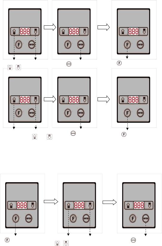
1.2.2 ENTER THE USER MODE TO MODIFY AND SAVE THE PARAMETER
|
|
|
|
|
|
|
|
|
|
|
|
|
|
|
|||
|
|
|
|
|
|
|
|
|
|
|
|
|
|
|
|
|
|
- 2 -
From the library of: Superior Sewing Machine & Supply LLC
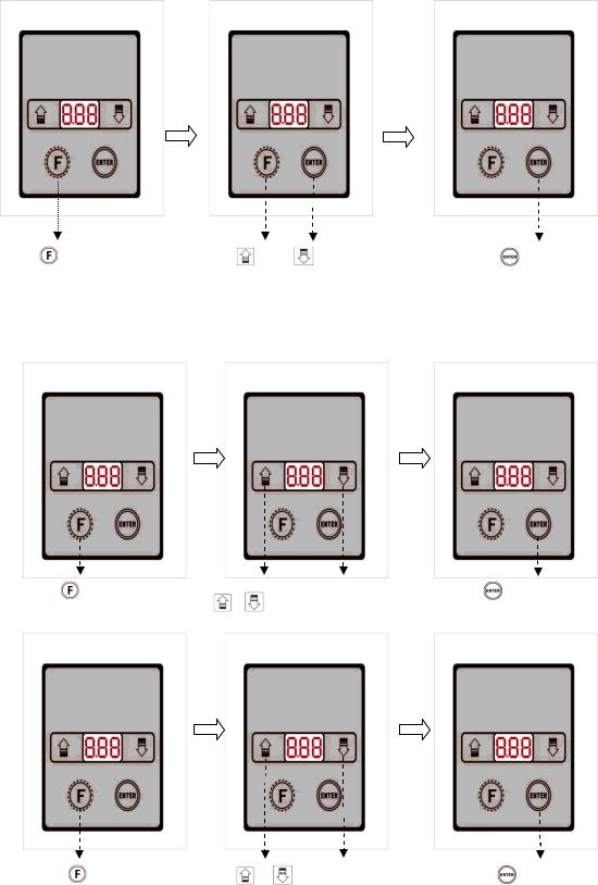
Press |
to enter the User |
|
Press |
and |
to change the |
|
Press |
to define enter |
parameter mode |
|
parameters |
|
|
|
|
the parameter |
|
|
|
|
|
|
|
|
|
|
|
|
|
|
|
|
|
|
|
|
|
|
|
|
|
|
|
|
1.3 ENTER THE TECHNICIAN MODE TO MODIFY AND SAVE THE PARAMETER
|
|
|
|
|
|
|
|
|
|
|
|
|
|
|
|||
|
|
|
|
|
|
|
|
|
|
|
|
|
|
|
|
|
|
|
|
|
|
|
|
|
|
|
Press |
and boot |
|
Press |
and |
to change the parameters |
|
Press |
to define |
|
|
|
|
|
|
|
|
|
- 3 -
From the library of: Superior Sewing Machine & Supply LLC
1.4THE INSTRUCTION OF DIGITAL TYPE
1.4.1LCD FONTS AND THE ACTUAL FONTS COMPARISION TABLE
digital part
|
|
|
|
|
|
|
|
|
|
|
|
The actual |
0 |
1 |
2 |
3 |
4 |
5 |
6 |
7 |
8 |
9 |
|
fonts |
|
|
|
|
|
|
|
|
|
|
|
|
|
|
|
|
|
|
|
|
|
|
|
LCD show |
|
|
|
|
|
|
|
|
|
|
|
1.4.2 THE LCD DISPLAY MODE |
|
|
|
|
|
||||||
|
A |
B |
C |
D |
E |
F |
G |
H |
I |
J |
|
English |
|||||||||||
|
|
|
|
|
|
|
|
|
|
||
|
|
|
|
|
|
|
|
|
|
|
|
LCD show |
|
|
|
|
|
|
|
|
|
|
|
|
K |
L |
M |
N |
O |
P |
Q |
R |
S |
T |
|
English |
|||||||||||
|
|
|
|
|
|
|
|
|
|
||
|
|
|
|
|
|
|
|
|
|
|
|
LCD show |
|
|
|
|
|
|
|
|
|
|
|
|
U |
V |
W |
X |
Y |
Z |
|
|
|
|
|
English |
|
|
|
|
|||||||
|
|
|
|
|
|
|
|
|
|
||
|
|
|
|
|
|
|
|
|
|
|
|
LCD show |
|
|
|
|
|
|
|
|
|
|
|
- 4 -
From the library of: Superior Sewing Machine & Supply LLC

2 & USER PARAMETER & TECHNICIAN PARAMERTER
2.1 USER PARAMETER
|
|
|
|
|
|
|
|
|
|
|
|
|
|
|
|
|
|
Sequence |
Instruction |
range |
default |
Setting key |
|
description |
||
number |
|
|
|
|
|
|
|
|
|
|
|
|
|
|
|
|
|
|
|
|
|
|
|
|
= |
|
P01 |
spm |
10 360 |
300 |
|
×10 |
|||
Max rotate speed |
|
The max rotate speed of machine |
||||||
|
|
|
|
|||||
|
|
|
|
|
|
|
actual speed=parameter×10 |
|
|
|
|
|
|
|
|
|
|
|
|
|
|
|
|
|
|
|
P02 |
spm |
20 360 |
130 |
|
= ×10 |
|||
Sewing speed |
|
|
Set the sewing speed actual speed = |
|||||
|
|
|
|
|
||||
|
|
|
|
|
|
|
parameter×10 |
|
|
|
|
|
|
|
|
|
|
|
|
|
|
|
= |
|||
|
|
|
|
×10 |
||||
P03 |
The |
speed |
of |
10 - 100 |
55 |
|
||
|
The speed of machine when it cutting |
|||||||
|
cutting |
|
|
|
|
|||
|
|
|
|
|
material actual speed = parameter×10 |
|||
|
|
|
|
|
|
|
||
|
|
|
|
|
|
|
|
|
|
|
|
|
|
|
= ×10 |
||
P04 |
first |
stitch |
speed |
10-360 |
80 |
|
||
|
actual speed=parameter×10 |
|||||||
|
limit |
|
|
|
|
|
||
|
|
|
|
|
|
|
|
|
|
|
|
|
|
|
= ×10 |
||
P05 |
second stitch speed |
10-360 |
80 |
|
||||
|
actual speed=parameter×10 |
|||||||
|
limit |
|
|
|
|
|
||
|
|
|
|
|
|
|
|
|
|
|
|
|
|
|
= ×10 |
||
P06 |
third |
stitch |
speed |
10-360 |
200 |
|
||
|
actual speed=parameter×10 |
|||||||
|
limit |
|
|
|
|
|
||
|
|
|
|
|
|
|
|
|
|
|
|
|
|
|
= ×10 |
||
P07 |
forth |
stitch |
speed |
10-360 |
250 |
|
||
|
actual speed=parameter×10 |
|||||||
|
limit |
|
|
|
|
|
||
|
|
|
|
|
|
|
|
|
|
|
|
|
|
|
= ×10 |
||
P08 |
fifth |
stitch |
speed |
10-360 |
200 |
|
||
|
actual speed=parameter×10 |
|||||||
|
limit |
|
|
|
|
|
||
|
|
|
|
|
|
|
|
|
|
s |
|
|
|
|
|||
|
|
|
|
|
||||
P9 |
Presser foot protection |
1 - 120 |
8 |
|
||||
|
Presser foot will lay down when |
|||||||
|
time |
|
|
|
|
|
||
|
|
|
|
|
|
beyond setting time |
||
|
|
|
|
|
|
|
||
|
|
|
|
|
|
|
||
|
|
|
|
|
|
|||
|
The |
stitches |
|
|
|
|||
P10 |
0-6 |
3 |
|
The |
stitches number with the |
|||
number with the |
|
|||||||
|
|
|
|
action of cutter |
||||
|
action of cutter |
|
|
|
||||
|
|
|
|
|
|
|||
- 5 -
From the library of: Superior Sewing Machine & Supply LLC

2.2 TECHNICIAN PARAMETER
|
|
|
|
|
|
|
|
|
|
|
|
|
|
|
|
|
|||
Sequence |
instruction |
range |
default |
|
|||||
|
|
|
|
||||||
number |
|
|
|
|
|
|
|
|
|
|
|
|
|
|
|
|
|
||
|
|
|
|
|
|
|
|||
|
(ms |
|
|
|
|
|
|||
P11 |
|
10 - 990 |
250 |
|
|
the time of presser foot full output |
|||
Full-on |
time |
setting |
|
|
|||||
|
|
|
|
|
to work |
||||
|
for presser foot (ms) |
|
|
|
|
||||
|
|
|
|
|
|
|
|||
|
|
|
|
|
|
|
|
||
|
|
|
|
|
|
|
|||
|
% |
|
|
|
|
|
|
||
P12 |
Duty |
cycle |
time |
10 - 90 |
30 |
|
|
when presser foot moving ,tht motor |
|
|
setting for presser foot |
|
|
|
|
periodic output to avoid the presser |
|||
|
(%) |
|
|
|
|
|
|
foot too hot |
|
|
|
|
|
|
|
|
|
|
|
|
|
|
|
|
|
|
|
|
|
|
|
|
|
|
|
|
|||
|
|
|
|
|
|
|
|
|
|
P13 |
(ms Mechanical |
10 - 990 |
560 |
|
|
When stepping the foot pedal, it will |
|
||
|
|
delayed the starting time to coordinate |
|
||||||
|
lock adjustment |
|
|
|
|
|
|||
|
|
|
|
|
the presser foot laying down |
|
|||
|
time(ms) |
|
|
|
|
|
|
||
|
|
|
|
|
|
|
|
||
|
|
|
|
|
|
|
|
||
|
|
|
|
|
|
|
|||
P14 |
Mechanical |
lock |
10 - 990 |
100 |
|
|
|||
|
|
Set mechanical lock open time |
|||||||
|
open time |
|
|
|
|
|
|||
|
|
|
|
|
|
|
|
||
|
|
|
|
|
|
|
|||
P15 |
Mechanical |
lock |
10 - 990 |
120 |
|
|
|||
|
|
Set mechanical lock close time |
|||||||
|
close time |
|
|
|
|
|
|||
|
|
|
|
|
|
|
|
||
|
|
|
|
|
|
|
|
||
|
|
|
|
|
|
|
|||
|
The |
stitches |
|
|
|
|
|||
P16 |
1 - 990 |
400 |
|
|
The number of needle moved to |
||||
number |
|
of |
|
|
|||||
|
|
|
|
|
|
protect under the solution of big plate |
|||
|
protection |
|
|
|
|
|
|||
|
|
|
|
|
|
without inducing . |
|||
|
|
|
|
|
|
|
|
||
|
|
|
|
|
|
|
|
|
|
|
|
|
|
|
|
1 |
|||
|
|
|
|
|
|
||||
|
|
|
|
|
|
|
|
||
P17 |
|
|
0 - 1 |
1 |
|
|
1:needle goes up as power on |
||
Needle goes up as |
|
|
|||||||
|
|
|
|
|
0 |
||||
|
power on |
|
|
|
|
|
|||
|
|
|
|
|
|
0: no function |
|||
|
|
|
|
|
|
|
|
||
|
|
|
|
|
|
|
|
|
|
|
|
|
|
|
|
|
|
|
|
|
|
|
|
|
|
|
|
||
|
|
|
|
|
|
when thenumberisreduced itwill |
|||
P18 |
Up needle position |
40 - 180 |
40 |
|
|
||||
|
|
stopearlier otherwiseitwilldelayed |
|||||||
|
adjustment |
|
|
|
|
|
|||
|
|
|
|
|
|
thestoppingtime. |
|||
|
|
|
|
|
|
|
|||
P19 |
|
1 - 250 |
20 |
|
|
C |
|||
Test working time |
|
|
Test working time of C, |
||||||
|
|
|
|
|
|||||
|
|
|
|
|
- 6 - |
|
|
|
|
From the library of: Superior Sewing Machine & Supply LLC

|
|
|
|
|
|
|
|
|
|
|
|
|
|
|
|
|
|
|
|
|
|||||
Sequence |
instruction |
range |
default |
|
|
|||||||
|
|
|
|
|
|
|
|
|||||
number |
|
|
|
|
|
|
|
|
|
|
|
|
|
|
|
|
|
|
|
|
|||||
P20 |
|
1 - 250 |
20 |
|
|
C |
||||||
Test stop time |
|
|
Test stop time of C |
|
|
|
||||||
|
|
|
|
|
|
|
|
|||||
|
|
|
|
|
|
|
A P01 |
|||||
P21 |
A |
0 - 1 |
0 |
|
|
|
|
|
||||
Item A testing |
|
|
|
|
|
|
|
|
||||
|
|
After |
set A test options, motor will |
|
||||||||
|
|
|
|
|
|
|||||||
|
|
|
|
|
|
|
work at P01 speed to continue testing |
|
||||
|
|
|
|
|
|
|
B P01 |
|||||
|
B |
|
|
|
|
|
|
|
||||
P22 |
0 - 1 |
0 |
|
|
After |
set |
B test |
options, |
motor will |
|||
Item B testing |
|
|
||||||||||
|
|
|
|
|
work at P01 speed to full-functionality |
|||||||
|
|
|
|
|
|
|
||||||
|
|
|
|
|
|
|
testing |
|
|
|
|
|
|
|
|
|
|
|
|
|
|||||
|
|
|
|
|
|
|
C P01 |
|||||
|
C |
|
|
|
|
|
|
|
||||
P23 |
0 - 1 |
0 |
|
|
After |
set |
item C testing |
, sewing |
||||
Item C testing |
|
|
||||||||||
|
|
|
|
|
machine |
can |
working |
without |
||||
|
|
|
|
|
|
|
||||||
|
|
|
|
|
|
|
positioning at the P01 speed |
|
|
|||
|
|
|
|
|
|
|
|
|
|
|||
|
|
|
|
|
|
|
0 |
|
|
|||
|
|
|
|
|
|
0 no sewing machine head protection |
||||||
P24 |
Sewing |
machine |
0 - 1 |
1 |
|
|
switch |
|
|
|
|
|
head |
protection |
|
|
1 |
|
|
||||||
|
|
|
|
|
|
|
||||||
|
switch |
|
|
|
|
|
1 open |
sewing machine head |
||||
|
|
|
|
|
|
|
protection switch |
|
|
|
||
|
|
|
|
|
|
|
|
|
|
|||
|
|
|
|
|
|
|
0 |
|
|
|||
|
|
|
|
|
|
0 no mechanical lock |
protection |
|||||
|
|
|
|
|
switch |
|
|
|
|
|
||
P25 |
Mechanical lock |
0 - 1 |
1 |
|
|
|
|
|
|
|
||
|
|
1 |
|
|
||||||||
|
protection switch |
|
|
|
|
|
|
|||||
|
|
|
|
|
1 open mechanical lock protection |
|||||||
|
|
|
|
|
|
|
||||||
|
|
|
|
|
|
|
switch |
|
|
|
|
|
|
|
|
|
|
|
|
|
|
|
|
|
|
- 7 -
From the library of: Superior Sewing Machine & Supply LLC
3 ERROR CODES TABLE
|
|
|
|
|
Error Code |
|
Cause |
Solution |
|
|
|
|
|
|
|
|
|
|
|
|
|
|
The module driver output with head power output will be |
|
|
1) |
|
shutting down. |
|
|
|
Error code of power module |
||
|
|
/ |
||
E1 |
2) |
|
||
Waiting for the power to re-open / reset |
||||
|
|
Abnormal over-current or |
||
|
|
|
||
|
|
over-voltage |
|
|
|
|
|
||
|
|
|
(Please check the power board of the each function) |
|
|
|
|
|
|
|
a) |
|
|
|
|
|
|
||
|
|
|
|
|
|
|
Motor connector caused bad turn. |
The module driver output with head power output will be |
|
|
|
|
||
|
b) |
shutting down. |
||
|
|
|
||
|
|
Locator signal abnormality. |
|
|
|
b) |
|
/ |
|
|
|
|||
|
|
|
Waiting for the power to re-open / reset. |
|
|
|
|
||
E7 |
|
The front agencies deadlock or the |
|
|
|
motor belt foreign body embroiled stuck. |
|
||
|
c) |
|
||
|
|
|
||
|
|
|
|
|
|
|
Processing the material is too thick, |
(Please check the front is stuck or locator motor module |
|
|
|
|
||
|
motor torque not sufficient throughout. |
drive signal is abnormal or not) |
||
|
|
|
||
|
e) |
|
||
|
|
Module driver output abnormality. |
|
|
|
|
|
|
|
|
|
|
|
|
E9 |
|
Check the upper and lower positioning signal is normal or |
||
|
Locator signal is abnormal. |
|||
|
|
not, or if belt pulley is too loose. |
||
|
|
|
||
|
|
|
|
|
|
|
|
|
|
|
|
|
||
|
Automatically enter into no locator mode, and tangent, |
|||
|
|
sweeping lines, positioning and all fixed stitch pattern |
||
|
|
sewing function doesn’t work. |
||
E11 |
The power is turned on automatically |
|||
|
||||
|
find on positioning. But locator is not |
|||
|
inserted into the control box, the |
The motor can be normal operation. |
||
|
|
|||
|
needle signal cannot be output. |
|||
|
(Please check locator is abnormal or not). |
|||
|
|
|
||
|
|
|
|
|
- 8 -
From the library of: Superior Sewing Machine & Supply LLC
|
|
|
|
|
|
|
|
|
|
Automatically enter into no locator mode, and tangent, |
|
|
|
sweeping lines, positioning and all fixed stitch pattern |
|
E12 |
The positioning device is not inserted |
sewing function doesn’t work. |
|
|
when power is turned on. |
|
|
|
|
The motor can be normal operation. |
|
|
|
|
|
|
|
(Please check locator is forgot to insert or abnormal) |
|
|
|
|
|
|
|
|
|
E13 |
Check the power module and heat sink is a good contact or |
||
Power module overheating protection |
|||
|
not. |
||
|
|
||
|
|
|
|
|
|
|
|
E14 |
Check encoder signal is normal or not, or replace the |
||
Encoder signal is abnormal. |
|||
|
encoder. |
||
|
|
||
|
|
|
|
|
|
|
|
|
|
The module driver output with head power output will be |
|
|
|
shutting down. |
|
E15 |
Power module is abnormal |
/ |
|
|
over-current protection. |
Waiting for the power to re-open / reset |
|
|
|
|
|
|
|
(Please check the power board of the each function) |
|
|
|
|
|
|
|
|
|
E17 |
The head protection switch is not to |
Check the machine head is opened or not, the switch is |
|
|
correct position. |
damaged or not. |
|
|
|
|
|
|
|
|
|
E18 |
Check mechanical lock protection switch is abnormal or not, |
||
Error code of mechanical lock |
|||
|
protection switch is damaged or not. |
||
|
|
||
|
|
|
|
|
|
|
|
E19 |
Check the low speed cam is normal, the sensor whether there |
||
Error code of the broader protection |
|||
|
is damage |
||
|
|
||
|
|
|
- 9 -
From the library of: Superior Sewing Machine & Supply LLC
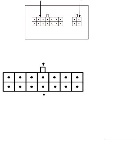
4 PORT SCHEMATIC DIAGRAM
4.1 NAMES OF EACH PORT
14P |
|
|
Function Port |
|
Foot Board Port |
|
|
|
4.2 14P FUNCTION PORT CORRESPONDING TABLE
14 |
|
13 |
|
12 |
|
11 |
|
10 |
|
9 |
|
8 |
|
|
|
|
|
|
|
|
|
|
|
|
|
7 |
|
6 |
|
5 |
|
4 |
|
3 |
|
2 |
|
1 |
|
|
|
|
|
|
|
|
|
|
|
|
|
|
5V |
|
|
|
|
||
The thread |
5V Clothing |
The end of induction |
Mechanical locks induction |
Mechanical lock |
Presser foot |
||
trimming solenoid |
headlights |
|
|
|
|
electromagnet |
lift |
|
|
|
|
|
|
|
|
1 |
2 0V |
4 0V |
|
12 |
11 +5V |
6 |
7 |
|
|
|
|
|
|
|
|
8 |
9 +5V |
10 +5V |
3 |
5 0V |
|
13 |
14 |
|
|
|
|
|
|
|
|
- 10 -
From the library of: Superior Sewing Machine & Supply LLC

5 INSTALLATION INSTRUCTIONS
5.1SPEED CONTROL PEDAL PULL ADJUSTMENT
A Front foot board tension spring
B Back riding the adjustment screws for tightness recoil group
C Pedal spiral arm lever hook hole
VD A C
Pedal connector retrofitting VD suction series device, suggest change install A and C just like the right diagram show.
|
|
|
|
VD |
||||||||||||||||||||||||||||||||
General installation |
|
|
|
|
|
|
|
|
||||||||||||||||||||||||||||
|
|
|
|
|
|
|
diagram |
Installation of the VD |
||||||||||||||||||||||||||||
|
|
|
|
|
|
|
|
|
|
|
|
|
|
|
|
|
|
|
|
suction wind device |
||||||||||||||||
|
|
|
|
|
|
|
|
|
|
|
|
|
|
|
|
|
|
|
|
installation diagram |
||||||||||||||||
|
|
|
|
|
|
|
|
|
|
|
|
|
|
|
|
|
|
|
|
|
|
|
|
|
|
|
|
|
|
|
|
|
|
|
|
|
|
|
|
|
|
|
|
|
|
|
|
|
|
|
|
|
|
|
|
|
|
|
|
|
|
|
|
|
|
|
|
|
|
|
|
|
|
|
|
|
|
|
|
|
|
|
|
|
|
|
|
|
|
|
|
|
|
|
|
|
|
|
|
|
|
|
|
|
|
|
|
|
|
|
|
|
|
|
|
|
|
|
|
|
|
|
|
|
|
|
|
|
|
|
|
|
|
|
|
|
|
|
|
|
|
|
|
|
|
|
|
|
|
|
|
|
|
|
|
|
|
|
|
|
|
|
|
|
|
|
|
|
|
|
|
|
|
|
|
|
|
|
|
|
|
|
|
|
|
|
|
|
|
|
|
|
|
|
|
|
|
|
|
|
|
|
|
|
|
|
|
|
|
|
|
|
|
|
|
|
|
|
|
|
|
|
|
|
|
|
|
|
|
|
|
|
|
|
|
|
|
|
|
|
|
|
|
|
|
|
|
|
|
|
|
|
|
|
|
|
|
|
|
|
|
|
|
|
|
|
|
|
|
|
|
|
|
|
|
|
|
|
|
|
|
|
|
|
|
|
|
|
|
|
|
|
|
|
|
|
|
|
|
|
|
|
|
|
|
|
|
|
|
|
|
|
|
|
|
|
|
|
|
|
|
|
|
|
|
|
|
|
|
|
|
|
|
|
|
|
|
|
|
|
|
|
|
|
|
|
|
|
|
|
|
|
|
|
|
|
|
|
|
|
|
|
|
|
|
|
|
|
|
|
|
|
|
|
|
|
|
|
|
|
|
|
|
|
|
|
|
|
|
|
|
|
|
|
|
|
|
|
|
|
|
|
|
|
|
|
5.2 INTEGRATED ELECTRONIC CONTROL INSTALLATION INSTRUCTIONS
1 Machine Head
2 Direct-motor
3 electronic control
- 11 -
From the library of: Superior Sewing Machine & Supply LLC
4 hand wheel
5 ×2 On fastening screws ×2 6 ×2 Middle fastening screws ×2 7 ×1 Under fastening screws ×1
Installation Instructions
2
Mounted male three-jaw connector on front-end shaft direct drive motor2, Corresponding spindle mounted on female three-jaw connector and rubber. The direction of motor and outlet is to right. Pay attention to relationship (motor positioning) of the direction of the spindle on the plane and the plane of the motor shaft, and then sets the motor into the spindle, the motor on the four fixing screws, the motor installed.
5
Take power control next to the motor, extract the encoder line on the electronic control plug to the motor encoder mouth, and then take the motor power head butt and electronically controlled power port, put inside the electric hole on the fastening screws 5, put the screws in position.
电控中间紧固螺钉6 6 5 7
Electronic control of the motor chamber alignment motor slowly set into the machine head, adjust the two cable placed on the right side of the electronic control perfectly. Fit into the intermediate fastening screws penetrate the electronic control not tight, the rotation on the fastening screws and machine. The connection does not tight to the head of the screw holes, and then penetrates the electronic control under the fastening screws, check and adjusts the contour and machine head contours of the electronic control with appropriate turn matter screws 6 screw 5, screws7, electrical control installed.
4
Put hand wheel 4 on the rear axle of motor, pay attention to the positioning screw axis plane aligned tightens.
- 12 -
From the library of: Superior Sewing Machine & Supply LLC

 Loading...