

Jac PE50p User guide

V01-01-2017
EN – FR – DE – NL – RU – ES – IT – AR

2

3
EN- Translation of original user instructions
PE50p volumetric divider ................................................................................................................... 5
FR- Notice d’utilisation originale
Peseuse PE50p .................................................................................................................................. 17
DE- Übersetzung der Originalanleitung
Abwieger PE50p ................................................................................................................................ 29
NL- Vertaling van de originele gebruikershandleiding
Verdeler PE50p .................................................................................................................................. 41
RU- Перевод оригинального руководства по эксплуатации
Весовой дозатор PE50p .................................................................................................................. 53
ES- Traducción del manual de uso original
Pesadora PE50p ................................................................................................................................ 65
IT- Traduzione delle informazioni sull'utilizzo originali
Dosatrice PE50p ................................................................................................................................ 77
ﻲﺳﻧر- ﻲﻠﺻﻷا مادﺧﺗﺳﻻا لﯾﻟد ﺔﻣﺟرﺗ
ﺔﻟآ نزو PE50p ........................................................................................................................................ 89

4

5
PE50p volumetric divider
1 BEFORE COMMISSIONING ......................................................................................................... 7
2 WARRANTY .................................................................................................................................. 7
3 WARNINGS ................................................................................................................................... 8
4 TECHNICAL SPECIFICATIONS ................................................................................................... 9
4.1 Technicalspecifications.............................................................................................................................................9
4.2 Detailsofmaterialsindirectcontactwithdough..............................................................................................9
5 INSTALLATION AND COMMISSIONING ................................................................................... 10
5.1 Unpackingthemachine:..........................................................................................................................................10
5.2 Positioning:..................................................................................................................................................................10
5.3 Electricalconnection:...............................................................................................................................................11
5.4 Commissioning:..........................................................................................................................................................11
5.5 Danger:..........................................................................................................................................................................12
6 CONTROLS AND SAFETY FEATURES ..................................................................................... 12
6.1 Controls:........................................................................................................................................................................12
6.2 Settingarea:.................................................................................................................................................................12
6.3 Workarea:...................................................................................................................................................................12
6.4 Safetyfeatures:...........................................................................................................................................................12
7 OPERATION ................................................................................................................................ 12
8 MAINTENANCE ........................................................................................................................... 13
8.1 Daily,byatrainedoperator...................................................................................................................................13
8.2 Weekly,byatrainedoperator...............................................................................................................................13
8.3 Annually,byanapprovedagent...........................................................................................................................13
9 CONSUMABLES ......................................................................................................................... 14
9.1 ListofCONSUMABLES...............................................................................................................................................14
10 MALFUNCTIONS ..................................................................................................................... 15
11 ERROR CODES ....................................................................................................................... 15
12 LIST OF COMPONENTS IN ILLUSTRATIONS ....................................................................... 16
English

6

7
1 BEFORE COMMISSIONING
Thank you for choosing a JAC system. It is essential that you read these instructions
before installing and commissioning this machine. This will protect you and avoid damaging
your machine.
These instructions refer to various illustrations in order to make them easier to understand.
These illustrations are at the end of the instructions. Please refer to them whenever you see
the following symbols: (fig.X, n°Y).
To ensure that your machine gives you full satisfaction over the coming years, we
invite you to familiarise yourself with the following advice:
- Enlist the help of your approved agent for installation, commissioning and service support.
- In order to be covered by the 5-year warranty (see terms and conditions set out below),
please have your dealer fill in the service booklet when your machine is being installed. The
service booklet is at the back of your machine.
2 WARRANTY
All JAC products are covered by a 5-year warranty.
This warranty is valid for all parts on your machine, including electronic components but
excluding consumables. The warranty takes effect on the date the equipment is installed.
Subject to the following restrictive conditions:
- Equipment acquired from an approved dealer;
- Installation carried out by an approved agent;
- Equipment used in accordance with the instructions for use and for the intended purpose
for which it was manufactured;
- Equipment serviced on a daily basis in compliance with the instructions for use;
- Regular servicing by the approved agent in compliance with service specifications, with
at least one service a year (servicing chargeable to the user).
- Exclusive use of genuine JAC parts.
If there is no record of servicing by an approved agent and/or if the service booklet
has not been filled in correctly, warranty cover will be limited to one year.
This warranty does not cover:
- Replacement of consumables (§9);
- Parts not accepted as defective by our company;
- Problems due to improper use of the equipment;
- Problems due to installation not carried out by an approved agent;
- Parts or problems due to transit damage or improper handling.
Repairing and/or replacing defective parts during the warranty period does not
bring about an extension of said warranty.
English
English

8
3 WARNINGS
It is most important that these user instructions be kept with the machine for any future
reference. Should this machine be sold or transferred to another user, please ensure that the
user instructions are handed over so that the new user can be familiarised with its operation
and the warnings associated with it.
These warnings are given for your safety and that of others. We would therefore
ask you to read them carefully before installing and using the machine.
This machine has been designed for use by authorised adults. Please therefore ensure
that children do not touch it or use it as a toy.
This machine is intended exclusively for professional use.
It is dangerous to modify or attempt to modify the specifications of this machine.
After having installed this machine, please ensure that it is not standing on the power
cable.
Follow the instructions given for its use.
This machine must be stored and used in an indoor room, protected from moisture and
heat.
This machine must be adequately illuminated to operate it.
The noise level of this machine does not exceed 75 dB(A) in accordance with EN ISO
3744.
This machine must be used by one person at a time (unless otherwise specified).
Always disconnect the mains supply before cleaning the machine inside/outside
and when carrying out maintenance.
This machine is heavy. Take all necessary safety precautions when handling it.
English
9
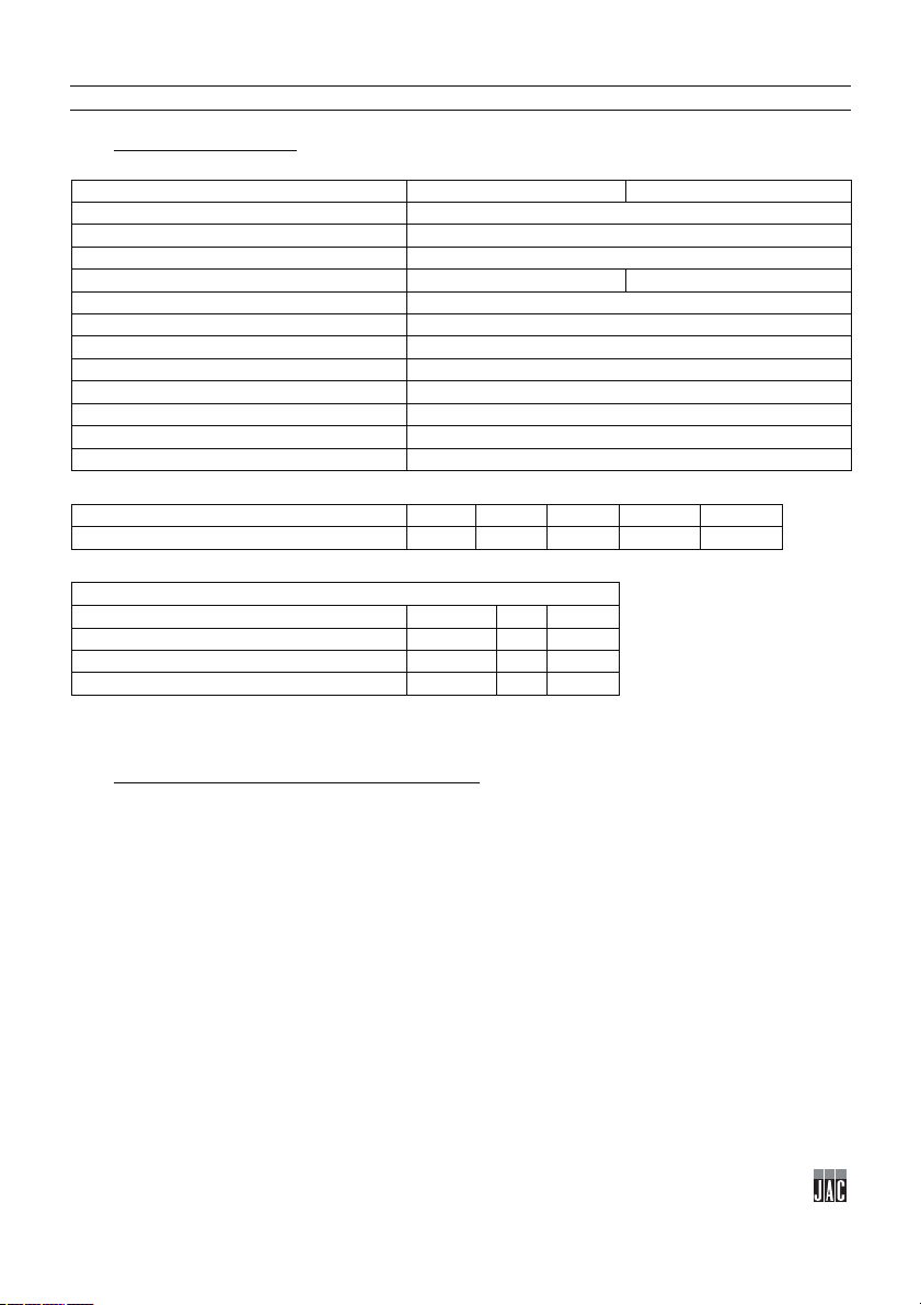
4 TECHNICAL SPECIFICATIONS
Short belt
Long belt
Height (mm)
1775
Hopper fill height
1463
Width (mm)
950
Depth (mm)
1348
1784
Hopper capacity (kg)
160
Packaging (mm)
1165 x 1030 x 830
Net weight (kg)
500
Net weight + packing (kg)
90
Motor power rating (kW)
2.4
Motor type
Three-phase
220 V - 50 Hz (A)
12
380 V - 50 Hz (A)
9.5
Ø74
Ø95
Ø109
Ø119
Ø131
Dough piece min./max. weights (g)
70/400
110/650
160/850
300/1000
400/1300
Production rate (pieces per hour)
STAND-ALONE configuration
960
1200
1400
PRO+ configuration
960
1200
1400
LPS configuration
1200
1800
PROLINE configuration
960 > 1800
4.1 Technical specifications
The minimum hydration rate required for optimum operation is 60%
4.2 Details of materials in direct contact with dough.
Hopper: TEFLON
Drum: STAINLESS STEEL
Piston: STEEL CASTING
Outfeed belt: FELT
English

10
5 INSTALLATION AND COMMISSIONING
5.1 Unpacking the machine:
Machines are delivered from our works on pallets, strapped and protected with cardboard. First of all,
the packaging must be examined and any damage caused in transit must be declared directly to the
carrier.
A. Remove the case.
B. Remove the side casings from the machine in order to gain access to the jacking screws
(fig.3).
C. Detach the machine from its pallet by unscrewing the jacking screws immobilising the
machine (fig.4).
D. Take the machine off the pallet. Make sure you do this with at least two people in order to
lower it as gently as possible onto the floor.
E. During machine installation, the pads must be fitted under the jacking screws (fig.5).
F. Fit the hopper on the machine. Make sure you do this with at least two people (fig.6).
G. Remove the cover allowing access to the hopper valve to enable the air line to be
connected between the valve and the fitting located under the pressure gauge, passing the
line through the duct running along the hopper (fig.7).
H. Open the hopper lid to connect the cable for its safety cut-out to the safety switch, passing
the cable through the tube and the duct running along the tank (fig.8).
I. Fit the outfeed belt (fig.9).
J. Connect the belt Harting connector (fig.10).
After unpacking your machine, check that it has not been damaged in transit. Notify
us of any defects.
5.2 Positioning:
In order to achieve excellent performance and long-term reliability, choose a location that is:
Well ventilated, shielded from direct sunlight and away from sources of heat, with a flat and
sturdy surface free from vibration.
English

11
5.3 Electrical connection:
IMPORTANT: This machine must be earthed.
It is recommended that the system be protected with a fuse and an RCD.
Your mains electricity supply to the machine must be protected as indicated below:
- North America: 15 A protection;
- Rest of the world: 16 A protection.
For machines equipped with a variable speed drive, it is imperative that they be connected to a
junction box on a circuit fitted with a 300 mA RCD.
Note: Any problem resulting from any other type of connection will not be covered under warranty.
Before connecting your machine to the mains supply and in order to prevent the motor from burning
out when it is switched on, it is important to check that the mains supply matches the machine
specification (see machine nameplate).
This machine complies with Machinery Directives 2006/42, 2006/95, 2004/108 and is CE marked as
proof of this.
Please familiarise yourself with the safety pictograms displayed on the machine:
This pictogram indicates an electrocution hazard. Please isolate the machine
before carrying out any work on it. You will find it at the back of the machine close
to the power cable and inside the machine on the electrical enclosure (fig.24).
You will find the circuit diagram for the machine on the back of the electrical
enclosure door (fig.25).
5.4 Commissioning:
Before commissioning, ensure that there are no extraneous objects interfering with the machine’s
moving parts.
Ensure first of all (after verifying electrical compatibility) that motors are rotating in the right
direction, this means that:
The cam is rotating clockwise (if not, reverse 2 phases at the variable speed drive).
The outfeed belt is running in the right direction (if not, reverse 2 phases at the motor
terminal box).
Check that the oil pump is operating correctly; it must operate continuously (if not, set the
pulse potentiometer to 90%).
Check that the oil indicator light on the control panel is not lit (if it is, add 5 litres of oil via the
oil filler plug).
For machine operation, refer to the “Operation” chapter.
English

12
5.5 Danger:
If the user or the machine is in danger, you must use the main isolator switch to cut the power supply
to the machine.
Keep clear of the tray proofers when they are in motion.
Remove the plug from the power socket before any maintenance and/or servicing work.
Any maintenance work or replacement of parts must be carried out by an approved agent.
6 CONTROLS AND SAFETY FEATURES
6.1 Controls:
Your machine is equipped as standard with a mechanical control panel (fig.2).
6.2 Setting area:
The setting area is located at the machine control panel (fig.11, n°18).
6.3 Work area:
The work area is located at the machine outfeed belt (fig.11, n°19).
6.4 Safety features:
This machine is equipped with:
A mechanical safety lock (fig.1, n°8) which prevents the machine from operating if the hopper lid is
not closed properly.
7 OPERATION
Switch on the power to the machine at the start of the day using the main isolator switch
(fig.1, n°16).
Operating procedure
A. Open the hopper lid (fig.12).
B. Lubricate the inside of the hopper using a spray can or a cloth dipped in grapeseed oil (fig.12).
C. Tip the dough into the hopper (fig.13).
D. Close the hopper lid (fig.13).
E. Set the desired weight for the dough pieces using the handwheel on the front of the machine
(fig.14).
(A position indicator is located next to the buttons).
F. Set the digital counter to determine the desired number of dough pieces (fig.14).
G. Select the speed (production rate) 1, 2 or 3 (fig.15).
H. Press the green button to start the cycle (fig.15).
The red button stops a cycle in progress (fig.1, n°12).
English

13
8 MAINTENANCE
8.1 Daily, by a trained operator.
A. Clean the residue tray (fig.16).
B. Clean the outfeed belt using a brush (fig.17).
C. Remove any dough deposits that might obstruct the air intake in the hopper using an oiled cloth
(fig.18).
D. Check the flour dispenser level (fig.19).
E. Clean the hopper (fig.20).
F. Clean the lid seal with an oiled cloth (fig.21).
G. Clean the scraper at the drum with an oiled cloth (fig.22).
H. Check whether the oil filter is clogged via the clogging indicator (fig.23).
8.2 Weekly, by a trained operator.
Clean the inside of the machine using a cloth and a soft brush.
Check and adjust as necessary the sealing of the hopper closure lid using an Allen key.
8.3 Annually, by an approved agent.
Check and adjust the outfeed belt tension using an open-ended spanner.
Check the cam bearing and piston rollers for wear using a screwdriver.
Check that the oil pump is operating correctly.
Check that the diaphragm compressor is operating correctly (0.3 bar gauge pressure).
Drain the oil.
Replace the piston seals (every year or 200,000 cycles).
Check that your approved agent has recorded his work in your service booklet in order to maintain
your 5-year warranty cover.
English

14
9 CONSUMABLES
ITEM CODE
NEW DESCRIPTION
MODEL
F3071100
FLOUR DISPENSER BRUSH
ALL
F8003092
DRUM SCRAPER BLADE
ALL
F8003098
PISTON SCRAPER BLADE
ALL
F8003172
OUTFEED BELT SCRAPER BLADE
ALL
F8002035
PISTON ROLLER
ALL
F8002032
CAM ROLLER
ALL
F8002106
GRAPESEED OIL
ALL
F8002101
SHORT OUTFEED BELT
ALL
F8002102
LONG OUTFEED BELT
ALL
F8002117
OIL FILTER
ALL
F8002076
O-RING, 74MM DIA.
ALL
F8002124
LIP SEAL, 74MM DIA.
ALL
F8002099
O-RING, 95MM DIA.
ALL
F8002125
LIP SEAL, 95MM DIA.
ALL
F8002042
O-RING, 109MM DIA.
ALL
F8002126
LIP SEAL, 109MM DIA.
ALL
F8002085
O-RING, 119MM DIA.
ALL
F8002127
LIP SEAL, 119MM DIA.
ALL
F8002107
O-RING, 131MM DIA.
ALL
F8002128
LIP SEAL, 131MM DIA.
ALL
F8002096
LID SEAL, PE50
ALL
F8002013
BEARING BLOCK
ALL
When ordering spare parts, check with your approved agent which part is required based on the
spare parts catalogue issued by the manufacturer.
Always quote the machine serial number shown on the nameplate.
Your agent will place the orders with JAC.
9.1 List of CONSUMABLES
English
15
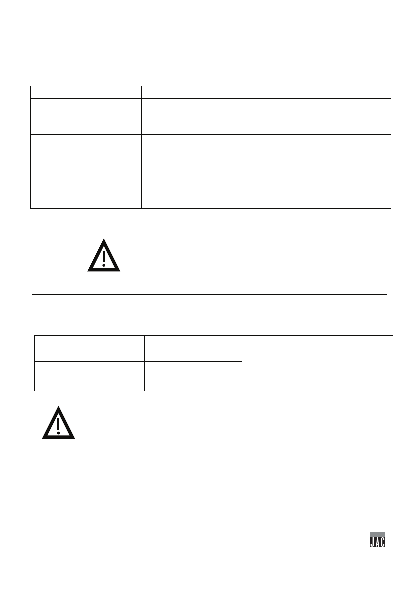
10 MALFUNCTIONS
Check its position.
Replace the seals.
code displayed on variable
speed drive
Action
WARNING: The machine must be isolated from the power supply before attempting any work on it.
Problem Check
The machine will not start
Check the main power supply.
Close the hopper lid.
Check its operating condition.
Weights are not consistent
11 ERROR CODES
LU Low voltage Check variable speed drive parameters.
OL Overload
OL1 Overload 1
OL2 Overload 2
Should the problem persist, please contact your technician.
Check for any air leaks (lid) or blockages in pipes.
Check that the pressure gauge is showing 0.3 bar.
Should the problem persist, please contact your technician.
Problem description
06.03
06.04
07.00
07.01
07.02
English

16
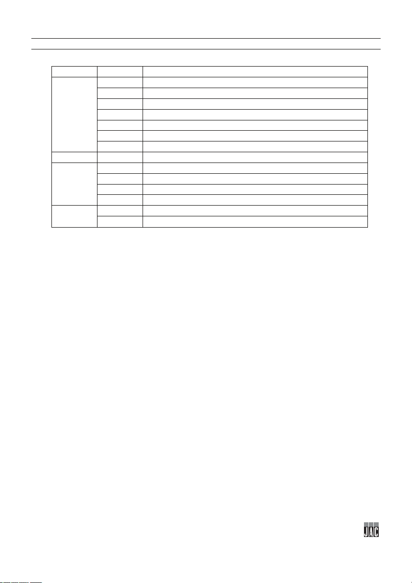
12 LIST OF COMPONENTS IN ILLUSTRATIONS
Figure
Item
Description
1
Belt
2
Belt tensioner
3
Control panel
4
Braked castor
5
Geared motor
6
Moulder fitting bracket
7
Flour recovery bin
2
8
Work area
9
Emergency stop
10
ON/OFF button
11
Start
12
Stop
13
Pictogram indicating an electrocution hazard
14
Electrical enclosure
1
3
4
English

17
Peseuse PE50p
1 AVANT LA MISE EN SERVICE ................................................................................................... 18
2 GARANTIE ................................................................................................................................... 18
3 AVERTISSEMENTS .................................................................................................................... 19
4 CARACTERISTIQUES TECHNIQUES ........................................................................................ 20
4.1 Caractéristiquestechniques..................................................................................................................................20
4.2 Détaildesmatériauxencontactdirectaveclapâte......................................................................................20
5 INSTALLATION ET MISE EN SERVICE ..................................................................................... 21
5.1 Déconditionnementdelamachine......................................................................................................................21
5.2 Emplacement...............................................................................................................................................................21
5.3 Raccordementélectrique........................................................................................................................................22
5.4 Miseenservice...........................................................................................................................................................22
5.5 Danger...........................................................................................................................................................................23
6 ORGANE DE COMMANDE ET DE SECURITE .......................................................................... 23
6.1 Organedecommande...............................................................................................................................................23
6.2 Zonederéglage..........................................................................................................................................................23
6.3 Zonedetravail............................................................................................................................................................23
6.4 Organesdesécurité..................................................................................................................................................23
7 UTILISATION ............................................................................................................................... 23
8 ENTRETIEN ................................................................................................................................. 24
8.1 Journalierparunutilisateurformé.....................................................................................................................24
8.2 Hebdomadaireparunutilisateurformé...........................................................................................................24
8.3 Annuelparunagentagréé......................................................................................................................................24
9 CONSOMMABLES ...................................................................................................................... 25
9.1 ListedesCONSOMMABLES......................................................................................................................................25
10 INCIDENTS DE FONCTIONNEMENT ..................................................................................... 26
11 CODES D’ERREUR ................................................................................................................. 26
12 LISTE DES COMPOSANTS SUR LES FIGURES ................................................................... 27
Français

18
1 AVANT LA MISE EN SERVICE
Merci d’avoir choisi une solution JAC. Veuillez impérativement lire ce mode d’emploi avant
d’installer et de mettre en service cette machine. Vous pourrez ainsi vous protéger et éviter
de détériorer votre machine.
Cette notice fait référence à différentes figures afin de faciliter la compréhension des
instructions. Ces figures se trouvent en fin de notice. Veuillez vous y référer dès que vous
rencontrez les symboles suivants (fig.x, n°y).
Pour que votre machine vous donne entière satisfaction au cours des prochaines
années, nous vous invitons à prendre connaissance des conseils suivants :
- Faites-vous aider par votre agent agréé pour l’installation, la mise en service et le suivi.
- Afin de pouvoir bénéficier de la garantie de 5 ans (voir conditions reprises ci-après),
faites compléter le carnet d’entretien par votre distributeur lors de l’installation de votre
machine. Ce carnet d’entretien se trouve à l’arrière de votre machine.
2 GARANTIE
JAC offre une garantie de 5 ans sur tous ses produits.
Cette garantie est valable sur toutes les pièces de votre machine, pièces électroniques
incluses, hors consommables. La garantie prend effet à la date d’installation du matériel.
Sous les conditions restrictives suivantes :
- matériel acquis auprès d’un revendeur agréé ;
- installation effectuée par un agent agréé ;
- utilisation du matériel conformément aux indications du mode d’emploi et dans le but
pour lequel il a été fabriqué ;
- matériel quotidiennement entretenu conformément aux indications du mode d’emploi ;
- entretiens suivis par l’agent agréé conformément aux spécifications d’entretien avec, au
minimum, un entretien par an (entretien à charge de l’utilisateur) ;
- utilisation exclusive des pièces d’origine JAC.
S’il n’y a pas de suivi d’entretien par un agent agréé et/ou que le carnet d’entretien
n’est pas correctement complété, la garantie se limite à un an.
Cette garantie ne couvre pas :
- le remplacement des consommables (§9) ;
- les pièces non reconnues défectueuses par nos services ;
- les problèmes résultant d’une utilisation anormale du matériel ;
- les problèmes résultant d’une installation non effectuée par un agent agréé ;
- les pièces ou les problèmes résultant d’un dégât de transport ou d’une manutention
inappropriée.
Français
Français

19
Une réparation et/ou un remplacement de pièces défectueuses effectué(es) durant
la période de garantie n’a (n’ont) pas pour effet de prolonger ladite garantie.
3 AVERTISSEMENTS
Il est très important que cette notice d'utilisation soit conservée avec l'appareil pour toute
future consultation. Si cet appareil devait être vendu ou transféré à une autre personne,
assurez-vous que la notice d'utilisation soit remise de façon à ce que l'utilisateur puisse être
informé de son fonctionnement et des avertissements s'y rapportant.
Ces avertissements sont donnés pour votre sécurité et pour celle d'autrui. Nous
vous prions donc de bien vouloir les lire attentivement avant d'installer et d'utiliser
l'appareil.
Cette machine a été conçue pour être utilisée par des adultes autorisés. Veillez donc à
ce que les enfants n'y touchent pas ou qu'ils ne l'utilisent pas comme un jouet.
Cette machine est exclusivement réservée à un usage professionnel.
Il est dangereux de modifier ou d'essayer de modifier les caractéristiques de cette
machine.
Après l’installation de cette machine, assurez-vous qu’elle ne repose pas sur le câble
d'alimentation.
Suivez les instructions données pour l'utilisation.
Cette machine doit être stockée et utilisée à l’intérieur, dans un local à l’abri de l’humidité
et de la chaleur.
Cette machine doit être suffisamment éclairée pour effectuer le travail.
Cette machine a un niveau sonore inférieur à 75 dB(A), suivant la norme EN ISO 3744.
Cette machine doit être utilisée par une seule personne à la fois (sauf prescription
contraire).
Toujours débrancher la prise de courant avant de procéder au nettoyage
intérieur/extérieur de l'appareil et aux opérations de maintenance.
Cet appareil est lourd. Prenez toutes les précautions de sécurité lors de sa manutention.
Français
20
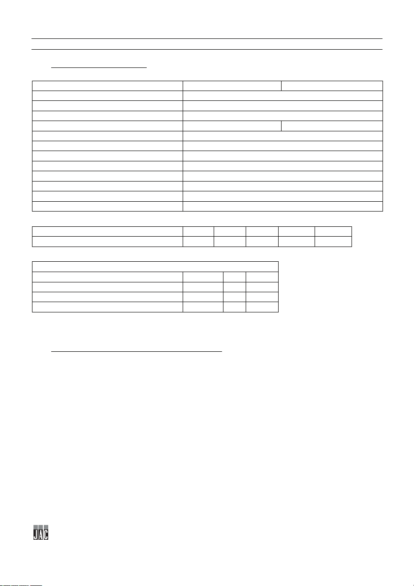
4 CARACTERISTIQUES TECHNIQUES
Tapis court
Tapis long
Hauteur (mm)
1775
Hauteur remplissage trémie (mm)
1463
Largeur (mm)
950
Profondeur (mm)
1348
1784
Capacité de la trémie (kg)
160
Colisage (mm)
1165 x1030 x 830
Poids net (kg)
500
Poids NET + emballage (kg)
90
Puissance moteur (kW)
2,4
Type moteur
Triphasé
220v - 50Hz (A)
12
380v - 50Hz (A)
9,5
Ø74
Ø95
Ø109
Ø119
Ø131
Poids des pâtons mini/maxi (g)
70 / 400
110 / 650
160 / 850
300 / 1000
400 / 1300
Cadence (pièces par heure)
Configuration AUTONOME
960
1200
1400
Configuration PRO+
960
1200
1400
Configuration LPS
1200
1800
Configuration PROLINE
960 > 1800
4.1 Caractéristiques techniques
Pour un fonctionnement parfait, le taux d’hydratation doit être de 60 % minimum.
4.2 Détail des matériaux en contact direct avec la pâte
Trémie : TEFLON
Tambour : INOX
Piston : FONTE D’ACIER
Tapis de sortie : FEUTRE
Français

21
5 INSTALLATION ET MISE EN SERVICE
5.1 Déconditionnement de la machine
Les machines sont livrées, sorties de nos ateliers, sur palettes, sanglées et protégées par du carton.
Avant toute chose, l'emballage doit être observé et tout dommage dû au transport doit être déclaré
directement au livreur.
A. Retirer la caisse.
B. Retirer les carters latéraux de la machine afin d’avoir accès aux vis vérin (fig.3).
C. Désolidariser la machine de sa palette en dévissant les vis vérin qui bloquent la machine
(fig.4).
D. Descendre la machine de la palette. Veiller à faire cette manipulation à au moins deux
personnes afin d’amortir au mieux le contact avec le sol.
E. Pendant la mise en place de la machine, les cales doivent être installées sous les vis vérin
(fig.5).
F. Mettre en place la trémie sur la machine. Veiller à faire cette manipulation à au moins deux
personnes (fig.6).
G. Retirer le capot permettant d’accéder au robinet de la trémie afin de pouvoir raccorder le
tuyau d’air entre le robinet et le raccord se trouvant en dessous du manomètre en passant
par la cornière longeant la trémie (fig.7).
H. Ouvrir le couvercle de la trémie de façon à raccorder le câble de la sécurité de celle-ci sur
l’interrupteur de sécurité en passant par le tube et la cornière longeant la cuve (fig.8).
I. Mettre en place le tapis de sortie (fig.9).
J. Raccorder la prise harting du tapis (fig.10).
Après déballage de la machine, vérifier qu'elle n'a pas subi de dommages pendant le
transport. Nous signaler toute anomalie.
5.2 Emplacement
Pour obtenir d'excellentes performances et une fiabilité à long terme, choisir un emplacement :
Bien ventilé, à l'abri du rayonnement solaire direct et éloigné des sources de chaleur, avec une
surface plane et robuste exempte de vibrations.
Français

22
5.3 Raccordement électrique
IMPORTANT : Mise à la terre obligatoire.
Il est conseillé de protéger l'installation avec un fusible et un disjoncteur différentiel.
Votre installation électrique alimentant la machine doit être protégée comme indiqué ci-dessous :
- Amérique du Nord : Protection 15A ;
- Reste du monde : Protection 16A.
Pour les machines équipées d’un variateur, celles-ci doivent être impérativement raccordées à une
boîte de dérivation sur une ligne équipée d’un différentiel de 300mA.
Note : Tout problème résultant d’un autre type de raccordement ne sera pas pris en compte par la
garantie.
Avant de connecter la machine au réseau et afin d'éviter une mise hors service du moteur à la mise
sous tension, il est important de vérifier la concordance du réseau d'alimentation avec les
caractéristiques de la machine (voir plaque signalétique de celle-ci).
Cet appareil est conforme aux Directives Machines 2006/42, 2006/95, 2004/108 et porte le marquage
CE attestant cette conformité.
Veuillez prendre connaissance des pictogrammes de sécurité figurant sur la machine :
Pictogramme signalant un risque d’électrocution. Veuillez débrancher la machine
avant toute intervention sur celle-ci. Vous retrouverez ce pictogramme à l’arrière
de la machine à proximité du câble d’alimentation et à l’intérieur de la machine sur
le coffret électrique (fig.24).
Vous trouverez le schéma électrique de la machine sur le verso de la porte du
coffret électrique (fig.25).
5.4 Mise en service
Avant la mise en service, s’assurer de l'absence de tout objet parasite sur les parties en mouvement
de la machine.
S'assurer tout d'abord (après vérification des concordances électriques) que les moteurs
tournent dans le bon sens ; il faut pour cela (que) :
la came tourne dans le sens horaire (sinon, inverser 2 phases au niveau du variateur) ;
le tapis de sortie tourne dans le bon sens (sinon, inverser 2 phases au niveau de la boîte à
borne du moteur) ;
vérifier le bon fonctionnement de la pompe à huile ; celle-ci doit fonctionner en continu
(sinon, régler le potentiomètre d’impulsion sur 90 %) ;
vérifier que le voyant d’huile sur le tableau de commande n’est pas allumé (si c’est le cas,
effectuer un remplissage de 5 L d’huile via le bouchon de remplissage d’huile).
Pour l’utilisation de la machine, se reporter au chapitre « Utilisation ».
Français

23
5.5 Danger
En cas de danger pour l’utilisateur ou pour la machine, utiliser l’interrupteur général pour couper
l’alimentation de la machine.
Ne pas s’approcher des balancelles quand celles-ci sont en mouvement.
Retirer la fiche de la prise électrique avant toute opération de maintenance et d’entretien.
Toute opération de maintenance ou de remplacement de pièce doit être effectuée par un agent agréé.
6 ORGANE DE COMMANDE ET DE SECURITE
6.1 Organe de commande
Votre machine est équipée de série d’un pupitre de commande mécanique (fig.2).
6.2 Zone de réglage
La zone de réglage se situe au niveau du pupitre de commande de la machine (fig.11, n°18).
6.3 Zone de travail
La zone de travail se situe au niveau du tapis de sortie de la machine (fig.11, n°19).
6.4 Organes de sécurité
Cette machine est équipée :
D’un verrou de sécurité mécanique (fig.1, n°8) qui empêche la machine de fonctionner si le
couvercle de la trémie n’est pas correctement fermé.
7 UTILISATION
En début de journée, mettre la machine sous tension à l’aide de l’interrupteur général
(fig.1, n°16).
Procédure d’utilisation
A. Ouvrir le couvercle de la trémie (fig.12).
B. Lubrifier l’intérieur de la trémie à l’aide d’une bombe ou d’un chiffon imbibé d’huile de pépin de
raisin (fig.12).
C. Déverser la pâte dans la trémie (fig.13).
D. Fermer le couvercle de la trémie (fig.13).
E. Régler le poids des pâtons souhaité à l’aide du volant situé à l’avant de la machine (fig.14)
(un indicateur de positions est situé à côté des boutons).
F. Régler le compteur digital afin d’établir le nombre de pâtons désiré (fig.14).
G. Sélectionner la vitesse (cadence) 1,2 ou 3 (fig.15).
H. Appuyer sur le bouton vert pour démarrer le cycle (fig.15).
Le bouton rouge permet d’arrêter un cycle en cours (fig.1, n°12).
Français

24
8 ENTRETIEN
8.1 Journalier par un utilisateur formé
A. Nettoyer le bac à résidus (fig.16).
B. Nettoyer le tapis de sortie à l’aide d’une brosse (fig.17).
C. Retirer les dépôts de pâte pouvant obstruer l’arrivée d’air dans la trémie à l’aide d’un chiffon huilé
(fig.18).
D. Vérifier le niveau du farineur (fig.19).
E. Nettoyer la trémie (fig.20).
F. Nettoyer le joint de couvercle à l’aide d’un chiffon huilé (fig.21).
G. Nettoyer le racleur au niveau du tambour à l’aide d’un chiffon huilé (fig.22).
H. Vérifier l’encrassement du filtre à huile via l’indicateur de colmatage (fig.23).
8.2 Hebdomadaire par un utilisateur formé
Nettoyer l’intérieur de la machine à l’aide d’un chiffon et d’une brosse souple.
Vérifier et ajuster si nécessaire l’étanchéité du couvercle de fermeture de la trémie à l’aide d’une clé
Allen.
8.3 Annuel par un agent agréé
Vérifier et ajuster la tension du tapis de sortie à l’aide d’une clé plate.
Vérifier l’usure du roulement de came et des galets de piston à l’aide d’un tournevis.
Vérifier le bon fonctionnement de la pompe à huile.
Vérifier le bon fonctionnement du compresseur à membrane (valeur de 0,3 bar au manomètre).
Vidanger l’huile.
Changer les joints de pistons (tous les ans ou tous les 200 000 cycles).
Bien vérifier que votre agent agréé enregistre son intervention dans votre carnet d’entretien afin de
conserver votre garantie de 5 ans.
Français

25
9 CONSOMMABLES
REFERENCE
NOUVEAU LIBELLE
MODELE
F3071100
BROSSE FARINEUR
TOUTES
F8003092
LAME RACLEUR TAMBOUR
TOUTES
F8003098
LAME RACLEUR PISTON
TOUTES
F8003172
LAME RACLEUR COURSIER
SORTIE
TOUTES
F8002035
GALET PISTON
TOUTES
F8002032
GALET CAME
TOUTES
F8002106
HUILE DE PEPIN DE RAISIN
TOUTES
F8002101
COURSIER SORTIE COURT
TOUTES
F8002102
COURSIER SORTIE LONG
TOUTES
F8002117
FILTRE A HUILE
TOUTES
F8002076
JOINT TORIQUE Ø74MM
TOUTES
F8002124
JOINT A LEVRE Ø74MM
TOUTES
F8002099
JOINT TORIQUE Ø95MM
TOUTES
F8002125
JOINT A LEVRE Ø95MM
TOUTES
F8002042
JOINT TORIQUE Ø109MM
TOUTES
F8002126
JOINT A LEVRE Ø109MM
TOUTES
F8002085
JOINT TORIQUE Ø119MM
TOUTES
F8002127
JOINT A LEVRE Ø119MM
TOUTES
F8002107
JOINT TORIQUE Ø131MM
TOUTES
F8002128
JOINT A LEVRE Ø131MM
TOUTES
F8002096
JOINT DE COUVERCLE PE50
TOUTES
F8002013
PALIER A ROULEMENT
TOUTES
Lors d’une commande d’une pièce de rechange, vérifier avec votre agent agréé de quelle pièce il
s’agit sur la base du catalogue de pièces de rechange émis par le fabricant.
Toujours préciser le numéro de machine comme indiqué sur la plaque signalétique.
Votre agent effectue les commandes auprès de JAC.
9.1 Liste des CONSOMMABLES
Français

26
10 INCIDENTS DE FONCTIONNEMENT
Vérifier sa position
Changer les joints
code affiché sur variateur
Description du problème
Action
ATTENTION : La machine doit obligatoirement être mise hors tension pour toute intervention.
Problème Vérification
La machine ne se met pas en
route
Vérifier l’alimentation générale
Fermer le couvercle de la trémie
Vérifier son état de fonctionnement
Les poids ne sont pas
réguliers
11 CODES D’ERREUR
LU Baisse de tension Vérifier les paramètres du variateur
OL Surcharge
OL1 Surcharge 1
OL2 Surcharge 2
Si le problème persiste, veuillez contacter votre technicien.
Vérifier les éventuelles fuites (couvercle) d’air ou l’encrassement des tuyaux
Vérifier la valeur de 0,3 bar au niveau du manomètre
Si le problème persiste, veuillez contacter votre technicien.
06.03
06.04
07.00
07.01
07.02
Français
27
12 LISTE DES COMPOSANTS SUR LES FIGURES
Figure
Bulle
Nom
1
Tapis
2
Tendeur tapis
3
Pupitre de commande
4
Roulette frein
5
Motoréducteur
6
Equerre adaptation façonneuse
7
Bac de récupération de la farine
2
8
Zone de travail
9
Arrêt d’urgence
10
Bouton de mise en route ON/OFF
11
Mise en marche
12
Arrêt
13
Pictogramme signalant un risque d’électrocution
14
Boîtier électrique
1
3
4
Français

28

29
Abwieger PE50p
1 VOR DER INBETRIEBNAHME ................................................................................................... 31
2 GARANTIE ................................................................................................................................... 31
3 WARNHINWEISE ........................................................................................................................ 32
4 TECHNISCHE DATEN ................................................................................................................. 33
4.1 TechnischeDaten......................................................................................................................................................33
4.2 MaterialienderTeile,dieinKontaktmitdemSchnittgutkommen.........................................................33
5 INSTALLATION UND INBETRIEBNAHME ................................................................................. 34
5.1 AuspackenderMaschine:.......................................................................................................................................34
5.2 Aufstellung:..................................................................................................................................................................34
5.3 AnschlussandieStromversorgung:....................................................................................................................35
5.4 Inbetriebnahme:........................................................................................................................................................35
5.5 Gefahr:...........................................................................................................................................................................36
6 BEDIENELEMENT UND SICHERHEITSVORRICHTUNG .......................................................... 36
6.1 Bedienelement:..........................................................................................................................................................36
6.2 Einstellbereich:..........................................................................................................................................................36
6.3 Arbeitsbereich:...........................................................................................................................................................36
6.4 Sicherheitseinrichtungen:......................................................................................................................................36
7 BEDIENUNG ................................................................................................................................ 36
8 INSTANDHALTUNG .................................................................................................................... 37
8.1 TäglichdurcheineneingewiesenenBediener:...............................................................................................37
8.2 WöchentlichdurcheineneingewiesenenBediener:.....................................................................................37
8.3 JährlichdurcheinenzugelassenenVertreter:.................................................................................................37
9 ERSATZTEILE ............................................................................................................................. 38
9.1 ERSATZTEILLISTE......................................................................................................................................................38
10 STÖRUNGEN UND FEHLER ................................................................................................... 39
11 FEHLERCODES ....................................................................................................................... 39
12 LISTE DER ABGEBILDETEN TEILE UND FUNKTIONEN ..................................................... 40
Deutsch

30
Deutsch
 Loading...