


V01-01-2017
EN – FR – DE – NL – RU – ES – IT – AR

2

3
Translation of original user instructions
EN-
HF moulders ......................................................................................................................................... 5
FR- Notice d’utilisation originale
Façonneuses HF ................................................................................................................................ 15
DE- Übersetzung der Originalanleitung
Langwirkmaschinen HF .................................................................................................................... 25
NL- Vertaling van de originele gebruikershandleiding
Vormgevers HF .................................................................................................................................. 35
RU. Перевод оригинального руководства по эксплуатации
Тестоформовочные машины HF .................................................................................................. 45
ES- Traducción del manual de uso original
Moldeadoras HF ................................................................................................................................ 57
IT- Traduzione delle informazioni sull'utilizzo originali
Formatrici HF ..................................................................................................................................... 69
ﻲﺳﻧرﻓ - ﺔﻣﺟرﺗ لﯾﻟد مادﺧﺗﺳﻻا لﺻﻷا
تﻻآ ﻜﺸﺗﻞﯿ ﻦﯿﺠﻌﻟا HF ................................................................................................................................ 81

4

5
HF moulders
1 BEFORE COMMISSIONING ......................................................................................................... 6
2 WARRANTY .................................................................................................................................. 6
3 WARNINGS ................................................................................................................................... 7
4 TECHNICAL SPECIFICATIONS ................................................................................................... 8
4.1 Technical specifications .................................................................................................................... 8
4.2 Details of materials in direct contact with dough. ........................................................................... 8
5 INSTALLATION AND COMMISSIONING ..................................................................................... 8
5.1 Unpacking the machine: .................................................................................................................... 8
5.2 Positioning: ......................................................................................................................................... 9
5.3 Electrical connection: ........................................................................................................................ 9
5.4 Commissioning: .................................................................................................................................. 9
5.5 Danger: .............................................................................................................................................. 10
6 CONTROLS AND SAFETY FEATURES ..................................................................................... 10
6.1 Controls: ............................................................................................................................................ 10
6.2 Work area: ......................................................................................................................................... 10
6.3 Safety features: ................................................................................................................................. 10
7 OPERATION ................................................................................................................................ 11
8 MAINTENANCE ........................................................................................................................... 12
8.1 Daily, by a trained operator. ............................................................................................................ 12
8.2 Weekly, by a trained operator. ......................................................................................................... 12
8.3 Six-monthly, by an approved agent. ............................................................................................... 12
9 CONSUMABLES ......................................................................................................................... 13
9.1 List of CONSUMABLES .................................................................................................................... 13
10 MALFUNCTIONS ..................................................................................................................... 13
11 LIST OF COMPONENTS IN ILLUSTRATIONS ....................................................................... 14
English

6
1 BEFORE COMMISSIONING
Thank you for choosing a JAC system. It is essential that you read these instructions
before installing and commissioning this machine. This will protect you and avoid damaging
your machine.
These instructions refer to various illustrations in order to make them easier to understand.
These illustrations are at the end of the instructions. Please refer to them whenever you see
the following symbols: (fig.X, n°Y).
To ensure that your machine gives you full satisfaction over the coming years, we
invite you to familiarise yourself with the following advice:
- Enlist the help of your approved agent for installation, commissioning and service support.
- In order to be covered by the 5-year warranty (see terms and conditions set out below),
please have your dealer fill in the service booklet when your machine is being installed. The
service booklet is at the back of your machine.
2 WARRANTY
All JAC products are covered by a 5-year warranty.
This warranty is valid for all parts on your machine, including electronic components but
excluding consumables. The warranty takes effect on the date the equipment is installed.
Subject to the following restrictive conditions:
- Equipment acquired from an approved dealer;
- Installation carried out by an approved agent;
- Equipment used in accordance with the instructions for use and for the intended purpose
for which it was manufactured;
- Equipment serviced on a daily basis in compliance with the instructions for use;
- Regular servicing by the approved agent in compliance with service specifications, with
at least one service a year (servicing chargeable to the user).
- Exclusive use of genuine JAC parts.
If there is no record of servicing by an approved agent and/or if the service booklet
has not been filled in correctly, warranty cover will be limited to one year.
This warranty does not cover:
- Replacement of consumables (§9);
- Parts not accepted as defective by our company;
- Problems due to improper use of the equipment;
- Problems due to installation not carried out by an approved agent;
- Parts or problems due to transit damage or improper handling.
Repairing and/or replacing defective parts during the warranty period does not
bring about an extension of said warranty.
English
English

7
3 WARNINGS
It is most important that these user instructions be kept with the machine for any future
reference. Should this machine be sold or transferred to another user, please ensure that the
user instructions are handed over so that the new user can be familiarised with its operation
and the warnings associated with it.
These warnings are given for your safety and that of others. We would therefore
ask you to read them carefully before installing and using the machine.
This machine has been designed for use by authorised adults. Please therefore ensure
that children do not touch it or use it as a toy.
This machine is intended exclusively for professional use.
It is dangerous to modify or attempt to modify the specifications of this machine.
After having installed this machine, please ensure that it is not standing on the power
cable.
Follow the instructions given for its use.
This machine must be stored and used in an indoor room, protected from moisture and
heat.
This machine must be adequately illuminated to operate it.
The noise level of this machine does not exceed 75 dB(A) in accordance with EN ISO
3744.
This machine must be used by one person at a time (unless otherwise specified).
Always disconnect the mains supply before cleaning the machine inside/outside
and when carrying out maintenance.
This machine is heavy. Take all necessary safety precautions when handling it.
English

8
4 TECHNICAL SPECIFICATIONS
HF
Min/max weight of dough pieces in grams
50/1300
Maximum production rate in pieces per hour
1800
Motor power rating (kW)
0.37
Motor type
Three-phase
Height x Width x Depth
540 x 956 x 1145
Net weight (kg)
180
Pointed end belt
optional
Infeed guides
optional
TRF20 outfeed belt
optional
TRF30 outfeed belt
optional
Standard wheeled base
optional
Wheeled base with storage
optional
Pre-elongation module
Self-contained flour dispenser
optional
Feed belt
optional
4.1 Technical specifications
4.2 Details of materials in direct contact with dough.
Chute: STAINLESS STEEL 304L.
Roller: Food-grade white PETP
Scraper blade: Lucoflex
Rolling belt: Stainless steel mesh
Elongation belt: Wool/Synthetic
Fixed elongation belt: Wool
Feed belt: ARCOT synthetic cloth.
optional
5 INSTALLATION AND COMMISSIONING
5.1 Unpacking the machine:
Machines are delivered from our works on pallets, strapped and protected with cardboard. First of all,
the packaging must be examined and any damage caused in transit must be declared directly to the
carrier.
A. Remove the cardboard from the machine.
B. Remove straps, taking particular care when they are released by cutting.
C. Detach the machine from the pallet.
D. Assemble the machine with its feet (for table-top arrangement only) (fig.15, n°24).
English

9
E. For installation on a base, remove the lower right and left-hand doors in order to gain
access to the feet, remove them and replace them with the screws provided with the base
(fig.16).
After unpacking your machine, check that it has not been damaged in transit. Notify
us of any defects.
5.2 Positioning:
In order to achieve excellent performance and long-term reliability, choose a location that is:
Well ventilated, shielded from direct sunlight and away from sources of heat, with a flat and
sturdy surface free from vibration.
5.3 Electrical connection:
IMPORTANT: This machine must be earthed.
It is recommended that the system be protected with a fuse and an RCD.
Your mains electricity supply to the machine must be protected as indicated below:
- North America: 15 A protection;
- Rest of the world: 16 A protection.
For machines equipped with a variable speed drive, it is imperative that they be connected to a
junction box on a circuit fitted with a 300 mA RCD.
Note: Any problem resulting from any other type of connection will not be covered under warranty.
Before connecting your machine to the mains supply and in order to prevent the motor from burning
out when it is switched on, it is important to check that the mains supply matches the machine
specification (see machine nameplate).
This machine complies with Machinery Directives 2006/42, 2006/95, 2004/108 and is CE marked as
proof of this.
Please familiarise yourself with the safety pictograms displayed on the machine:
This pictogram indicates an electrocution hazard. Please isolate the machine
before carrying out any work on it. You will find it on the control panel, which acts
as an electrical enclosure (fig.9, n°23).
You will find the circuit diagram for the machine inside the electrical enclosure
(fig.9, n°23).
5.4 Commissioning:
Before commissioning, ensure that there are no extraneous objects interfering with the machine’s
moving parts.
Ensure first of all (after verifying electrical compatibility) that the motor is rotating in the right direction.
Do this by pressing the start button and checking that the front box belt goes upwards.
If this is not the case, disconnect immediately and switch two phase wires in the plug.
English

10
For machine operation, please refer to the “Operation” chapter.
5.5 Danger:
If the user or the machine is in danger, you must use the main isolator switch to cut the power supply
to the machine.
Keep clear of the tray proofers when they are in motion.
Remove the plug from the power socket before any maintenance and/or servicing work.
Any maintenance work or replacement of parts must be carried out by an approved agent.
6 CONTROLS AND SAFETY FEATURES
6.1 Controls:
Your machine is equipped as standard with a mechanical control panel (fig.3).
6.2 Work area:
The work area is located in front of the machine outfeed belt (fig.2, n°6).
6.3 Safety features:
This machine is equipped with the following safety features:
- A lever switch (fig.7, n°17) which stops the machine from operating if the chute is pulled forwards.
- An encoded magnetic switch (fig.7, n°18) which prevents the machine from starting if the front
housing is open.
- An emergency stop button (fig.3, n°7).
- On versions with a feed belt (optional), an encoded magnetic switch (fig.8, n°19) which stops the
machine from operating if the protective cover is raised (fig.8, n°20).
English

11
7 OPERATION
Rolling
Elongation
300 g baguette
19
11.5
300 g short
19
15
400 g long loaf
18
17
520 g loaf
18
14
800 g short loaf
16
15
1.8 kg long loaf
14
12
1.8 kg short loaf
16
8
50 g long roll
12
15.5
F
t
Pre-settings:
The table below provides recommended settings. However, the nature of the dough and the moulding
to be obtained must be taken into account. Trial and error is therefore often necessary and it is
essential to take into account the relationships between each of the settings.
For instance, insufficient rolling or elongation which is too tight results in an unattractive dough piece.
Rolling is adjusted with the upper handwheel (fig.3, n°8) (rotate clockwise to bring the rollers closer
together).
Elongation is adjusted with the lower handwheel (fig.3, n°12) (rotate clockwise to tighten the
elongation plate).
The resulting quality of moulding is dependent not only on the settings, but also on factors including:
- The aptitude of the dough to be moulded properly (sufficient but not excessive proofing,
“strength” but not excessive, etc.).
- A well-presented dough piece with a regular shape.
NOTE:
In order for the dough to be moulded and elongated properly, it is essential to flour:
- The box belt.
- The elongation belt.
A. Twist the mushroom (emergency stop) button ¼ turn to the right if it has not been released (fig.10).
B. Press the START button to start the machine (fig.11).
C. Insert the dough pieces into the secure infeed chute (fig.12).
D. Collect the moulded dough pieces from the delivery belt (fig.13).
E. Press the STOP button to stop the machine (fig.14).
For reasons of food hygiene, under no circumstances must dough or flour left on the top of
the machine or outside it, be reused or reintroduced into the food chain.
English

12
8 MAINTENANCE
8.1 Daily, by a trained operator.
On finishing work, clean the machine in order to prevent flour from accumulating, which could be
detrimental to its operation.
Measure the rolling dimension and, if necessary, brush the belts (do not use a metal dough cutter
to do this).
Open the elongation setting (fig.3, n°12) to its maximum extent in order to help the belts dry through
air circulation.
If there is excessive moisture, dismantle the entire elongation belt.
8.2 Weekly, by a trained operator.
Remove and clean the roller scrapers as follows:
(This must be done with the power to the machine switched off).
A. Open the front cover and remove it by releasing the two catches (fig.4, n°14).
B. Separate the rollers to the maximum extent using the setting handwheel (fig.3, n°8).
C. Pull the fixed roller scraper forward (fig.5, n°15) (unhook the right-hand and left-hand springs if
need be).
D. Clean the blade (check that there are no dough residues left).
E. Refit the scraper by locating each end in its mount and taking care to keep each spring in its stop
groove.
F Pull the adjustable roller scraper forward (fig.6, n°16) (unhook the right-hand and left-hand springs
if need be).
G. Clean the blade (check that there are no dough residues left).
H. Refit the scraper by locating each end in its mount and taking care to keep each spring in its stop
groove.
8.3 Six-monthly, by an approved agent.
Ensure that there is no abnormal noise when the machine is in operation. At the same time check the
belt for correct centring and tension.
Make the necessary adjustments as required.
The machine must be shut down.
Check chain condition and tension (lubricate if necessary).
Ensure the rolling and elongation setting handwheels are operating correctly.
Lubricate the screws if necessary.
Check the screw and its bearings for correct alignment.
Check that the belt is still in good condition (it is easy to determine simply by touch when its thickness
becomes critical).
Check that the elongation belt is in good condition.
English

13
9 CONSUMABLES
ITEM CODE
NEW DESCRIPTION
MODEL
F4505003
WOOLTOP BOX BELT
ALL
F4505003L
WOOL BOX BELT
ALL
F5440095
ELONGATION BELT
ALL
F5408011
CHAIN MESH BELT
ALL
F5442003
SCRAPER BLADE
ALL
F5442007
RH SCRAPER SPRING
ALL
F5442008
LH SCRAPER SPRING
ALL
F54700001
FEED BELT
ALL
F5412009L
PRE-ELONGATION BELT
ALL
Problem
Check
motor.
Check safety features (emergency stop button, chute
safety cut-out, front cover safety cut-out).
Check protective cover safety cut-out (feed belt option).
When ordering spare parts, check with your approved agent which part is required based on the
spare parts catalogue issued by the manufacturer.
Always quote the machine serial number shown on the nameplate.
Your agent will place the orders with JAC.
9.1 List of CONSUMABLES
10 MALFUNCTIONS
Check the main power supply and the power supply to the
The machine will not start
The motor is humming but will not start
Products emerging from elongation are
torn and unattractive.
WARNING: The machine must be isolated from the power supply before attempting any work on it.
Should the problem persist, please contact your technician.
Check that a phase is not missing in the electric circuit.
Check the power supply to the motor.
Check belt tension.
Check scrapers for appearance and cleanliness.
Check that there is no dough crust on the belts.
Check felt for cleanliness (pointed ends option).
Check elongation and rolling settings.
English

14
11 LIST OF COMPONENTS IN ILLUSTRATIONS
Figure
Item
Description
1
Secure infeed chute
2
Delivery belt
3
Delivery table
4
Heavy-duty belt assembly
5
Drive
2
6
Work area
7
Emergency stop button
8
Rolling setting
9
Rolling indicator
10
Start button
11
Stop button
12
Elongation setting
13
Elongation indicator
4
14
Front cover
5
15
Adjustable roller scraper
6
16
Fixed roller scraper
17
Lever switch
18
Encoded magnetic switch
19
Encoded magnetic switch
20
Protective cover (feed belt option).
21
Flour dispenser (optional)
22
Pictogram indicating an electrocution hazard
23
Circuit diagram
15
24
Adjustable feet (table-top only)
1
3
7
8
9
English

15
Façonneuses HF
1 AVANT LA MISE EN SERVICE ................................................................................................... 16
2 GARANTIE ................................................................................................................................... 16
3 AVERTISSEMENTS .................................................................................................................... 17
4 CARACTERISTIQUES TECHNIQUES ........................................................................................ 18
4.1 Caractéristiques techniques ............................................................................................................ 18
4.2 Détail des matériaux en contact direct avec la pâte ...................................................................... 18
5 INSTALLATION ET MISE EN SERVICE ..................................................................................... 18
5.1 Déconditionnement de la machine ................................................................................................. 18
5.2 Emplacement .................................................................................................................................... 19
5.3 Raccordement électrique ................................................................................................................. 19
5.4 Mise en service ................................................................................................................................. 19
5.5 Danger ............................................................................................................................................... 20
6 ORGANE DE COMMANDE ET DE SECURITE .......................................................................... 20
6.1 Organe de commande ...................................................................................................................... 20
6.2 Zone de travail .................................................................................................................................. 20
6.3 Organes de sécurité ......................................................................................................................... 20
7 UTILISATION ............................................................................................................................... 21
8 ENTRETIEN ................................................................................................................................. 22
8.1 Journalier par un utilisateur formé ................................................................................................. 22
8.2 Hebdomadaire par un utilisateur formé .......................................................................................... 22
8.3 Semestriel par un agent agréé ........................................................................................................ 22
9 CONSOMMABLES ...................................................................................................................... 23
9.1 Liste des CONSOMMABLES ............................................................................................................ 23
10 INCIDENTS DE FONCTIONNEMENT ..................................................................................... 23
11 LISTE DES COMPOSANTS SUR LES FIGURES ................................................................... 24
Français

16
1 AVANT LA MISE EN SERVICE
Merci d’avoir choisi une solution JAC. Veuillez impérativement lire ce mode d’emploi avant
d’installer et de mettre en service cette machine. Vous pourrez ainsi vous protéger et éviter
de détériorer votre machine.
Cette notice fait référence à différentes figures afin de faciliter la compréhension des
instructions. Ces figures se trouvent en fin de notice. Veuillez vous y référer dès que vous
rencontrez les symboles suivants (fig.x, n°y).
Pour que votre machine vous donne entière satisfaction au cours des prochaines
années, nous vous invitons à prendre connaissance des conseils suivants :
- Faites-vous aider par votre agent agréé pour l’installation, la mise en service et le suivi.
- Afin de pouvoir bénéficier de la garantie de 5 ans (voir conditions reprises ci-après),
faites compléter le carnet d’entretien par votre distributeur lors de l’installation de votre
machine. Ce carnet d’entretien se trouve à l’arrière de votre machine.
2 GARANTIE
JAC offre une garantie de 5 ans sur tous ses produits.
Cette garantie est valable sur toutes les pièces de votre machine, pièces électroniques
incluses, hors consommables. La garantie prend effet à la date d’installation du matériel.
Sous les conditions restrictives suivantes :
- matériel acquis auprès d’un revendeur agréé ;
- installation effectuée par un agent agréé ;
- utilisation du matériel conformément aux indications du mode d’emploi et dans le but
pour lequel il a été fabriqué ;
- matériel quotidiennement entretenu conformément aux indications du mode d’emploi ;
- entretiens suivis par l’agent agréé conformément aux spécifications d’entretien avec, au
minimum, un entretien par an (entretien à charge de l’utilisateur) ;
- utilisation exclusive des pièces d’origine JAC.
S’il n’y a pas de suivi d’entretien par un agent agréé et/ou que le carnet d’entretien
n’est pas correctement complété, la garantie se limite à un an.
Cette garantie ne couvre pas :
- le remplacement des consommables (§9) ;
- les pièces non reconnues défectueuses par nos services ;
- les problèmes résultant d’une utilisation anormale du matériel ;
- les problèmes résultant d’une installation non effectuée par un agent agréé ;
- les pièces ou les problèmes résultant d’un dégât de transport ou d’une manutention
inappropriée.
Une réparation et/ou un remplacement de pièces défectueuses effectué(es) durant
la période de garantie n’a (n’ont) pas pour effet de prolonger ladite garantie.
Français
Français

17
3 AVERTISSEMENTS
Il est très important que cette notice d'utilisation soit conservée avec l'appareil pour toute
future consultation. Si cet appareil devait être vendu ou transféré à une autre personne,
assurez-vous que la notice d'utilisation soit remise de façon à ce que l'utilisateur puisse être
informé de son fonctionnement et des avertissements s'y rapportant.
Ces avertissements sont donnés pour votre sécurité et pour celle d'autrui. Nous
vous prions donc de bien vouloir les lire attentivement avant d'installer et d'utiliser
l'appareil.
Cette machine a été conçue pour être utilisée par des adultes autorisés. Veillez donc à
ce que les enfants n'y touchent pas ou qu'ils ne l'utilisent pas comme un jouet.
Cette machine est exclusivement réservée à un usage professionnel.
Il est dangereux de modifier ou d'essayer de modifier les caractéristiques de cette
machine.
Après l’installation de cette machine, assurez-vous qu’elle ne repose pas sur le câble
d'alimentation.
Suivez les instructions données pour l'utilisation.
Cette machine doit être stockée et utilisée à l’intérieur, dans un local à l’abri de l’humidité
et de la chaleur.
Cette machine doit être suffisamment éclairée pour effectuer le travail.
Cette machine a un niveau sonore inférieur à 75 dB(A), suivant la norme EN ISO 3744.
Cette machine doit être utilisée par une seule personne à la fois (sauf prescription
contraire).
Toujours débrancher la prise de courant avant de procéder au nettoyage
intérieur/extérieur de l'appareil et aux opérations de maintenance.
Cet appareil est lourd. Prenez toutes les précautions de sécurité lors de sa manutention.
Français

18
4 CARACTERISTIQUES TECHNIQUES
HF
Poids min/max des pâtons en g
50/1300
Cadence maximum en pièces/h
1800
Puissance moteur (kW)
0,37
Type moteur
Triphasé
Hauteur x Largeur x Profondeur
540 x 956 x 1145
Poids net (kg)
180
Tapis bout pointus
option
Guides d’entrée
option
Tapis d’évacuation TRF20
option
Tapis d’évacuation TRF30
option
Socle standard sur roulettes
option
Socle avec rangements
option
Module de pré-allongement
Farineur autonome
option
Tapis d’alimentation
option
4.1 Caractéristiques techniques
4.2 Détail des matériaux en contact direct avec la pâte
Goulotte : INOX 304L.
Cylindre de laminage : PETP alimentaire blanc
Lame racleur : Lucoflex
Tapis d’enroulement : Mailles acier inoxydable
Tapis allongement : Laine / Synthétique
Tapis allongement fixe : Laine
Tapis d'alimentation : Toile synthétique ARCOT
option
5 INSTALLATION ET MISE EN SERVICE
5.1 Déconditionnement de la machine
Les machines sont livrées, sorties de nos ateliers, sur palettes, sanglées et protégées par du carton.
Avant toute chose, l'emballage doit être observé et tout dommage dû au transport doit être déclaré
directement au livreur.
A. Retirer le carton de la machine.
B. Enlever les sangles en faisant particulièrement attention à la détente de ces dernières lors
de leur sectionnement.
C. Désolidariser la machine de sa palette.
D. Monter la machine avec ses pieds (seulement pour un montage sur table) (fig.15, n°24).
Français

19
E. Pour un montage sur socle, enlever les portes inférieures droite & gauche afin d'avoir accès
aux pieds, les retirer et les remplacer par les vis prévues avec le socle (fig.16).
Après déballage de la machine, vérifier qu'elle n'a pas subi de dommages pendant le
transport. Nous signaler toute anomalie.
5.2 Emplacement
Pour obtenir d'excellentes performances et une fiabilité à long terme, choisir un emplacement :
Bien ventilé, à l'abri du rayonnement solaire direct et éloigné des sources de chaleur, avec une
surface plane et robuste exempte de vibrations.
5.3 Raccordement électrique
IMPORTANT : Mise à la terre obligatoire.
Il est conseillé de protéger l'installation avec un fusible et un disjoncteur différentiel.
Votre installation électrique alimentant la machine doit être protégée comme indiqué ci-dessous :
- Amérique du Nord : Protection 15A ;
- Reste du monde : Protection 16A.
Pour les machines équipées d’un variateur, celles-ci doivent être impérativement raccordées à une
boîte de dérivation sur une ligne équipée d’un différentiel de 300mA.
Note : Tout problème résultant d’un autre type de raccordement ne sera pas pris en compte par la
garantie.
Avant de connecter la machine au réseau et afin d'éviter une mise hors service du moteur à la mise
sous tension, il est important de vérifier la concordance du réseau d'alimentation avec les
caractéristiques de la machine (voir plaque signalétique de celle-ci).
Cet appareil est conforme aux Directives Machines 2006/42, 2006/95, 2004/108 et porte le marquage
CE attestant cette conformité.
Veuillez prendre connaissance des pictogrammes de sécurité figurant sur la machine :
Pictogramme signalant un risque d’électrocution. Veuillez débrancher la machine
avant toute intervention sur celle-ci. Vous retrouverez ce pictogramme sur le
panneau de commande qui fait office de boîtier électrique (fig.9, n°23).
Vous trouverez le schéma électrique de la machine à l’intérieur du coffret
électrique (fig.9, n°23).
5.4 Mise en service
Avant la mise en service, s’assurer de l'absence de tout objet parasite sur les parties en mouvement
de la machine.
S'assurer tout d'abord (après vérification des concordances électriques) que le moteur tourne dans le
bon sens. Pour cela, donner une impulsion et vérifier que le tapis de caisson avant va vers le haut.
S'il n'en est pas ainsi, débrancher immédiatement et inverser, dans la prise, deux fils de phase.
Français

20
Pour l’utilisation de la machine, se reporter au chapitre « Utilisation ».
5.5 Danger
En cas de danger pour l’utilisateur ou pour la machine, utiliser l’interrupteur général pour couper
l’alimentation de la machine.
Ne pas s’approcher des balancelles quand celles-ci sont en mouvement.
Retirer la fiche de la prise électrique avant toute opération de maintenance et d’entretien.
Toute opération de maintenance ou de remplacement de pièce doit être effectuée par un agent agréé.
6 ORGANE DE COMMANDE ET DE SECURITE
6.1 Organe de commande
Votre machine est équipée de série d’un pupitre de commande mécanique (fig.3).
6.2 Zone de travail
La zone de travail se situe devant le tapis de sortie de la machine (fig.2, n°6).
6.3 Organes de sécurité
Cette machine est équipée de sécurités :
- un interrupteur à levier (fig.7, n°17) qui arrête le fonctionnement si l'on tire la goulotte vers l'avant ;
- un interrupteur magnétique codé (fig.7, n°18) qui interdit la mise en marche si le carter avant est
ouvert ;
- un bouton d’arrêt urgence (fig.3, n°7) ;
- sur les versions avec Tapis d’alimentation (en option), un interrupteur magnétique codé (fig.8, n°19)
qui arrête le fonctionnement si l'on soulève le capot de protection (fig.8, n°20).
Français

21
7 UTILISATION
Laminage
Allongement
Baguette 300 g
19
11,5
Court 300 g
19
15
Pain long 400 g
18
17
Pain 520 g
18
14
Pain court 800 g
16
15
Pain long 1,8 kg
14
12
Pain court 1,8 kg
16
8
Petit pain long 50 g
12
15,5
P
m
a
Préréglages
Le tableau ci-dessous fournit des indications pour effectuer les réglages. Toutefois, il faut prendre en
compte la nature de la pâte et le façonnage à obtenir. Un tâtonnement est donc souvent nécessaire
et il est indispensable de tenir compte de la relation qui existe entre chacun des réglages.
Par exemple, un laminage insuffisant ou un allongement trop serré donne un pâton de mauvais
aspect.
Le laminage s'effectue avec la molette supérieure (fig.3, n°8) (Tourner dans le sens des aiguilles
d'une montre serre les rouleaux).
L'allongement s'effectue avec la molette inférieure (fig.3, n°12) (Tourner dans le sens des aiguilles
d'une montre serre la plaque d'allonge).
Le résultat qualitatif du façonnage dépend des réglages mais également, entre autres, de :
- l'aptitude de la pâte à être bien façonnée (détente suffisante mais non excessive,
« force » sans excès...) ;
- la forme régulière du pâton et sa bonne présentation.
REMARQUE :
Afin que le façonnage et l'allongement s'effectuent dans de bonnes conditions, il est indispensable de
fariner :
- le tapis du caisson ;
- le tapis d'allongement.
A. Tourner d'1/4 de tour vers la droite le bouton coup de poing (arrêt d'urgence), s'il n'est pas
actionné (fig.10).
B. Appuyer sur le bouton MARCHE, afin de mettre la machine en marche (fig.11).
C. Insérer les pâtons dans la goulotte sécurisée d’entrée (fig.12).
D. Récupérer les pâtons mis en forme sur le tapis de réception (fig.13).
E. Appuyer sur le bouton ARRET, afin de mettre la machine en arrêt (fig.14).
Pour des raisons d'hygiène alimentaire, la pâte ou la farine se trouvant sur le dessus de la
machine ou en dehors ne peut en aucun cas être réutilisée ou remise dans la chaîne
alimentaire.
Français

22
8 ENTRETIEN
8.1 Journalier par un utilisateur formé
À la fin du travail, nettoyer la machine afin d'éviter l'accumulation de farine pouvant nuire à son bon
fonctionnement.
Relever la cote d'enroulement et, si nécessaire, brosser les tapis (pour cette opération, ne pas
utiliser de coupe-pâte métallique).
Ouvrir le réglage de l'allongement (fig.3, n°12) au maximum afin de faciliter le séchage des tapis par
la circulation d'air.
En cas d’humidité excessive, démonter l'ensemble tapis d'allonge.
8.2 Hebdomadaire par un utilisateur formé
Retirer et nettoyer les racleurs des cylindres de laminage de la manière suivante :
(opération à effectuer machine hors tension)
A. Ouvrir le capot de façade et le retirer à l’aide des deux verrous (fig.4, n°14).
B. Ecarter les rouleaux de laminage au maximum à l’aide de la manivelle de réglage (fig.3, n°8).
C. Tirer vers l'avant le racleur laminage fixe (fig.5, n°15) (décrocher au besoin les ressorts droit et
gauche).
D. Nettoyer la lame (vérifier l'absence de tout résidu de pâte).
E. Remonter le racleur en plaçant chaque extrémité dans les supports en prenant soin de maintenir
chaque ressort dans la gorge de sa butée.
F. Tirer vers l'avant le racleur de laminage réglable (fig.6, n°16) (décrocher au besoin les ressorts
droit et gauche).
G. Nettoyer la lame (vérifier l'absence de tout résidu de pâte).
H. Remonter le racleur en plaçant chaque extrémité dans les supports en prenant soin de maintenir
chaque ressort dans la gorge de sa butée.
8.3 Semestriel par un agent agréé
Lorsque la machine est en fonctionnement, s’assurer qu'il n'y a aucun bruit anormal. Vérifier en
même temps le bon centrage ainsi que la bonne tension du tapis.
S'il y a lieu, effectuer les réglages nécessaires.
Machine impérativement arrêtée.
Vérifier l'état ainsi que la tension de la chaîne (graisser si nécessaire).
S'assurer du bon fonctionnement des molettes de réglage laminage et allonge.
Graisser les vis si nécessaire.
S'assurer du bon alignement de la vis et de ses paliers.
Vérifier le bon état du tapis (par simple toucher, il est facile de déterminer lorsque l'épaisseur devient
critique).
Contrôler le bon état du tapis d'allongement.
Français

23
9 CONSOMMABLES
REFERENCE
NOUVEAU LIBELLE
MODELE
F4505003
COURSIER CAISSON
WOOLTOP
TOUTES
F4505003L
COURSIER CAISSON LAINE
TOUTES
F5440095
TAPIS ALLONGEMENT
TOUTES
F5408011
TAPIS COTTE DE MAILLE
TOUTES
F5442003
LAME RACLEUR
TOUTES
F5442007
RESSORT RACLEUR DROIT
TOUTES
F5442008
RESSORT RACLEUR GAUCHE
TOUTES
F54700001
COURSIER ALIMENTATION
TOUTES
F5412009L
TAPIS PREALLONGE
TOUTES
Problème
Vérification
Vérifier les organes de sécurité (bouton d’arrêt urgence,
sécurité goulotte, sécurité capot façade)
Vérifier la sécurité du capot de protection (option tapis
d'alimentation)
Lors d’une commande d’une pièce de rechange, vérifier avec votre agent agréé de quelle pièce il
s’agit sur la base du catalogue de pièces de rechange émis par le fabricant.
Toujours préciser le numéro de machine comme indiqué sur la plaque signalétique.
Votre agent effectue les commandes auprès de JAC.
9.1 Liste des CONSOMMABLES
10 INCIDENTS DE FONCTIONNEMENT
Vérifier l'alimentation générale et celle du moteur
La machine ne se met pas en route
Le moteur ronronne mais ne démarre pas
Les produits en sortie d’allonge sont
déchirés et n’ont pas un bel aspect.
ATTENTION : La machine doit obligatoirement être mise hors tension pour toute intervention.
Si le problème persiste, veuillez contacter votre technicien.
Vérifier s'il ne manque pas une phase dans le circuit
électrique
Vérifier l’alimentation du moteur
Vérifier la tension du tapis
Vérifier l'aspect et la propreté des racleurs
Vérifier l'absence de croûton de pâte sur les tapis
Vérifier la propreté du feutre (option bouts pointus)
Vérifier les réglages d'allongement et de laminage
Français

24
11 LISTE DES COMPOSANTS SUR LES FIGURES
Figure
Bulle
Nom
1
Goulotte sécurisée d’entrée
2
Tapis de réception
3
Tablette de réception
4
Ensemble tapis lourd
5
Motorisation
2
6
Zone de travail
7
Bouton d’arrêt d’urgence
8
Réglage laminage
9
Témoin de laminage
10
Bouton de mise en marche
11
Bouton d’arrêt
12
Réglage d’allongement
13
Témoin d’allongement
4
14
Capot de façade
5
15
Racleur rouleau réglable
6
16
Racleur rouleau fixe
17
Interrupteur à levier
18
Interrupteur magnétique codé
19
Interrupteur magnétique codé
20
Capot de protection (option tapis d’alimentation)
21
Farineur (option)
22
Pictogramme signalant un risque d’électrocution
23
Schéma électrique
15
24
Pieds réglables (uniquement sur table)
1
3
7
8
9
Français

25
Langwirkmaschinen HF
1 VOR DER INBETRIEBNAHME ................................................................................................... 26
2 GARANTIE ................................................................................................................................... 26
3 WARNHINWEISE ........................................................................................................................ 27
4 TECHNISCHE DATEN ................................................................................................................. 28
4.1 Technische Daten ............................................................................................................................. 28
4.2 Materialien der Teile, die in Kontakt mit dem Schnittgut kommen .............................................. 28
5 INSTALLATION UND INBETRIEBNAHME ................................................................................. 28
5.1 Auspacken der Maschine: ............................................................................................................... 28
5.2 Aufstellung: ....................................................................................................................................... 29
5.3 Anschluss an die Stromversorgung: .............................................................................................. 29
5.4 Inbetriebnahme: ................................................................................................................................ 30
5.5 Gefahr: ............................................................................................................................................... 30
6 BEDIENELEMENT UND SICHERHEITSVORRICHTUNG .......................................................... 30
6.1 Bedienelement: ................................................................................................................................. 30
6.2 Arbeitsbereich: ................................................................................................................................. 30
6.3 Sicherheitseinrichtungen: ............................................................................................................... 30
7 BEDIENUNG ................................................................................................................................ 31
8 INSTANDHALTUNG .................................................................................................................... 32
8.1 Täglich durch einen eingewiesenen Bediener: .............................................................................. 32
8.2 Wöchentlich durch einen eingewiesenen Bediener: ..................................................................... 32
8.3 Halbjährlich durch einen zugelassenen Vertreter: ........................................................................ 32
9 ERSATZTEILE ............................................................................................................................. 33
9.1 ERSATZTEILLISTE ........................................................................................................................... 33
10 STÖRUNGEN UND FEHLER ................................................................................................... 33
11 LISTE DER ABGEBILDETEN TEILE UND FUNKTIONEN ..................................................... 34
Deutsch

26
1 VOR DER INBETRIEBNAHME
Vielen Dank, dass Sie sich für ein Gerät von JAC entschieden haben. Bitte lesen Sie diese
Bedienungsanleitung vor der Installation und Inbetriebnahme dieser Maschine aufmerksam
durch. Dies dient zu Ihrer Sicherheit und zum Schutz der Maschine vor Schäden.
Diese Bedienungsanleitung enthält Verweise auf verschiedene Abbildungen, die das
Verständnis der Anleitungen erleichtern. Die Abbildungen befinden sich am Schluss der
Bedienungsanleitung. Bitte schlagen Sie die jeweilige Abbildung anhand des angegebenen
Verweises (Fig. X, Nr. Y) nach.
Damit Sie sich viele Jahre an dieser Maschine erfreuen können, möchten wir Sie
bitten, die folgenden Hinweise zu berücksichtigen:
- Lassen Sie sich bei der Installation, der Inbetriebnahme und der weiteren Nutzung von
Ihrem zugelassenen Vertreter unterstützen.
- Um die Garantie von fünf Jahren (siehe nachfolgende Garantiebestimmungen) in
Anspruch nehmen zu können, lassen Sie bitte von Ihrem Vertriebshändler bei der Installation
Ihrer Maschine das Wartungsheft ausfüllen. Das Wartungsheft befindet sich an der Rückseite
Ihrer Maschine.
2 GARANTIE
JAC bietet auf alle seine Produkte eine Garantie von fünf Jahren.
Diese Garantie erstreckt sich auf alle Teile Ihrer Maschine, auch auf die elektronischen
Bauteile, außer Verschleißteile. Die Garantiefrist beginnt zum Zeitpunkt der Installation der
Anlage.
Es gelten die folgenden Beschränkungen:
- Das Produkt wurde bei einem zugelassenen Vertragshändler erworben.
- Die Installation wurde von einem zugelassenen Vertreter vorgenommen.
- Das Produkt wurde im Rahmen seines bestimmungsgemäßen Gebrauchs und
entsprechend der Bedienungsanleitung verwendet.
- Das Produkt wurde täglich entsprechend den Vorgaben der Bedienungsanleitung
instandgehalten.
- Die Wartung wird durch einen zugelassenen Vertreter entsprechend den
Wartungsvorgaben durchgeführt und findet mindestens einmal jährlich statt (auf Kosten des
Anwenders).
- Es werden ausschließlich Originalersatzteile von JAC verwendet.
Sofern keine Wartung durch einen zugelassenen Vertreter erfolgt bzw. das
Wartungsheft nicht ordnungsgemäß ausgefüllt ist, ist die Garantie auf ein Jahr
begrenzt.
Diese Garantie deckt nicht:
- den Ersatz von Verschleißteilen (siehe Abschnitt 9);
- Teile, die unser Kundendienst nicht als defekt anerkennt;
Deutsch
Deutsch

27
- Probleme, die sich aus einer ungewöhnlichen Nutzung des Produktes ergeben;
- Probleme, die darauf zurückzuführen sind, dass die Installation nicht durch einen
zugelassenen Vertreter durchgeführt wurde;
- Beschädigungen oder Probleme, die auf einen Transportschaden oder auf die
unsachgemäße Handhabung des Produktes zurückzuführen sind.
Die Durchführung einer Reparatur und/oder der Ersatz defekter Teile während der
Garantiefrist führen nicht zur Verlängerung der Garantiefrist.
3 WARNHINWEISE
Bitte bewahren Sie diese Bedienungsanleitung unbedingt mit Ihrem Gerät zum späteren
Nachlesen auf. Bei Verkauf oder Weitergabe Ihres Gerätes übergeben Sie bitte diese
Bedienungsanleitung an den neuen Besitzer bzw. Benutzer, damit dieser über die
Funktionsweise des Gerätes und die Warnhinweise informiert ist und diese befolgen kann.
Diese Warnhinweise dienen zu Ihrer Sicherheit und der Sicherheit anderer. Bitte
lesen Sie die Warnhinweise vor der Installation und Verwendung Ihres Gerätes
aufmerksam durch.
Diese Maschine ist für die Verwendung durch befugte erwachsene Personen bestimmt.
Stellen Sie sicher, dass die Maschine nicht von Kindern berührt oder als Spielzeug benutzt
wird.
Diese Maschine ist ausschließlich für den professionellen Einsatz vorgesehen.
Eine Modifizierung bzw. versuchte Modifizierung der Eigenschaften und Merkmale dieser
Maschine ist gefährlich.
Stellen Sie nach der Installation dieser Maschine sicher, dass diese nicht auf dem
Netzkabel steht.
Befolgen Sie stets die Anleitungen zur Bedienung und Verwendung.
Die Maschine ist in einem Innenraum und gegen Feuchtigkeit und Hitze geschützt
aufzustellen.
Die Maschine muss zur Durchführung der Arbeiten ausreichend ausgeleuchtet sein.
Der Geräuschpegel der Maschine liegt unter 75 dB(A) und entspricht damit der
EN ISO 3744.
Die Maschine darf nicht von mehreren Personen gleichzeitig benutzt werden (es sei
denn, die Anleitung gibt etwas Anderes vor).
Vor Reinigungsarbeiten innen und außen am Gerät und vor Wartungsarbeiten
immer den Netzstecker ziehen.
Deutsch

28
Dieses Gerät ist sehr schwer. Beim Transport und Bewegen des Gerätes sind
HF
Min./max. Gewicht der Teiglinge (in g)
50/1300
Max. Arbeitsgeschwindigkeit in Stück/Stunde
1800
Motorleistung (kW)
00:37
Motortyp
dreiphasig
Höhe x Breite x Tiefe
540 x 956 x 1145
Nettogewicht (kg)
180
Band für Spitzenden
Option
Zufuhrführungen
Option
Austragsband TRF20
Option
Austragsband TRF30
Option
Standard-Rollgestell
Option
Rollgestell mit Blechablage
Option
Vorausrollmodul
Option
Unabhängiger Bemehler
Option
Zuführband
Option
angemessene Vorsichtsmaßnahmen zu ergreifen.
4 TECHNISCHE DATEN
4.1 Technische Daten
4.2 Materialien der Teile, die in Kontakt mit dem Schnittgut kommen
Führung: EDELSTAHL 304L
Walzzylinder: PETP weiß, nahrungsmittelfest
Abstreifermesser: Lucoflex
Aufwickelband: Edelstahlmaschen
Ausrollband: Wolle / Synthetik
Feststehendes Ausrollband: Wolle
Zuführband: Synthetikgewebe ARCOT.
5 INSTALLATION UND INBETRIEBNAHME
5.1 Auspacken der Maschine:
Unsere Maschinen werden zur Lieferung ab Werk auf Paletten verpackt, mit Umreifungsbändern
gesichert und mit einer Kartonverpackung geschützt. Prüfen Sie die Verpackung bei Erhalt auf
Beschädigungen und teilen Sie dem Spediteur etwaige Transportschäden direkt mit.
A. Den Karton entfernen.
B. Entfernen Sie die Umreifungsbänder und bedenken Sie dabei, dass diese beim
Durchschneiden aufspringen.
C. Heben Sie die Maschine von der Palette.
Deutsch

29
D. Die Maschine mit den Füßen montieren (nur bei einer Tischmontage) (Fig. 15, Nr. 24).
E. Für die Montage auf dem Sockel die rechte und linke Innentür ausbauen, um Zugang zu
den Füßen zu erhalten und diese entfernen und durch die Schrauben ersetzen, die für den
Sockel vorgesehen sind (Fig. 16).
Die Maschine nach dem Auspacken auf Transportschäden überprüfen. Melden Sie
uns bitte alle Fehler und Schäden.
5.2 Aufstellung:
Um eine hohe Leistung, eine lange Lebensdauer und einen zuverlässigen Betrieb sicherzustellen,
sollte der Aufstellort wie folgt beschaffen sein:
Gut belüftet, vor direkter Sonneneinstrahlung geschützt, in ausreichender Entfernung zu
Wärmequellen, mit ebenem, tragfähigen und schwingungsfreien Boden.
5.3 Anschluss an die Stromversorgung:
WICHTIG: Die Erdung der Maschine ist vorgeschrieben.
Wir empfehlen den Schutz der Anlage durch eine Sicherung und einen FISchutzschalter.
Ihr Stromnetz zur Versorgung der Maschine muss folgendermaßen geschützt werden:
- Nordamerika: Schutz 15 A;
- Rest der Welt: Schutz 16 A.
Maschinen mit Stromrichter müssen zwingend über einen FI-Schutzschalter für 300 mA
angeschlossen werden.
Hinweis: Probleme und Störungen, die sich durch abweichende Ausführung des Anschlusses
ergeben, sind nicht durch die Garantie gedeckt.
Prüfen Sie vor dem Anschließen der Maschine an das Stromnetz unbedingt, ob die Stromversorgung
für die Maschine geeignet ist (siehe Angaben auf dem Typenschild), um einen Motorausfall beim
Einschalten zu vermeiden.
Dieses Gerät entspricht den Maschinenrichtlinien 2006/42, 2006/95, 2004/108 und ist daher mit dem
CE-Zeichen gekennzeichnet.
Bitte beachten Sie die an der Maschine angebrachten Warnsymbole:
Warnsymbol zur Anzeige der Gefahr eines tödlichen Stromschlags. Die Maschine
vor jedem Eingriff vom Stromnetz nehmen. Dies befindet sich auf dem
Bedienelement, das auch als Schaltschrank verwendet wird. (Fig. 9, Nr. 23)
Der Schaltplan der Maschine befindet sich im Schaltschrank (Fig. 9, Nr. 23).
Deutsch

30
5.4 Inbetriebnahme:
Vor der Inbetriebnahme sicherstellen, dass sich keine Fremdkörper auf den beweglichen Teilen der
Maschine befinden.
Zunächst (nach Überprüfung der elektrischen Übereinstimmung) sicherstellen, dass der Motor in die
richtige Richtung dreht. Dazu einen Impuls geben und überprüfen, ob das Band des vorderen
Gehäuses nach oben läuft.
Soweit das nicht der Fall ist, die Maschine sofort vom Netz nehmen und in der Steckdose die
beiden Phasen umkehren.
Weitere Informationen zur Verwendung der Maschine erhalten Sie im Abschnitt „Bedienung“.
5.5 Gefahr:
Bei einer Gefahr für den Anwender oder die Maschine ist die Maschine über den Hauptschalter
auszuschalten.
Nicht in die Nähe der Gehänge kommen, wenn diese bewegt werden.
Vor Wartungs- oder Instandsetzungsmaßnahmen den Netzstecker ziehen.
Wartungsmaßnahmen und der Austausch von Ersatzteilen dürfen nur durch einen zugelassenen
Vertreter durchgeführt werden.
6 BEDIENELEMENT UND SICHERHEITSVORRICHTUNG
6.1 Bedienelement:
Ihre Maschine ist serienmäßig mit einem mechanischen Bedienpult ausgestattet (Fig. 3).
6.2 Arbeitsbereich:
Der Arbeitsbereich befindet sich vor dem Austragsband (Fig. 4, Nr. 6).
6.3 Sicherheitseinrichtungen:
Diese Maschine ist mit folgenden Sicherheitseinrichtungen ausgestattet:
- einem hebelgeführten Schalter (Fig. 7, Nr. 17), der den Betrieb unterbricht, wenn die Führung nach
vorn gezogen wird.
- einem codierten Magnetschalter (Fig. 7, Nr. 18), der bei geöffnetem Gehäuse das Einschalten
verhindert.
- einem Not-Aus-Schalter (Fig. 3, Nr. 7).
- Bei den Ausführungen mit Zuführband (Option), mit einem codierten Magnetschalter (Fig. 8, Nr. 19),
der den Betrieb unterbricht, wenn die Schutzabdeckung angehoben wird (Fig. 8, Nr. 20).
Deutsch

31
7 BEDIENUNG
Walzen
Ausrollen
Baguette 300 g
19
11.5
Kurz 300 g
19
15
Langes Brot 400 g
18
17
Brot 520 g
18
14
Kurzes Brot 800 g
16
15
Langes Brot 1.8 kg
14
12
Kurzes Brot 1.8 kg
16
8
Kleines langes Brot
50 g
12
15.5
A
o
N
Voreinstellungen:
Die Tabelle oben zeigt die Hinweise zu den einzelnen Einstellungen. Selbstverständlich ist dabei die
Art des Teigs und der Langwirkung zu berücksichtigen. Dementsprechend muss man sich häufig an
die richtigen Werte herantasten und das Verhältnis zwischen den einzelnen Einstellungen ist
zwingend zu berücksichtigen.
Ein unzureichendes Walzen oder ein zu enges Ausrollen führen beispielsweise zu unansehnlichen
Teiglingen.
Das Walzen wird am oberen Drehrad (Fig. 3, Nr. 8) eingestellt. (Das Drehen im Uhrzeigersinn führt
die Walzen enger zusammen).
Das Ausrollen wird am unteren Drehrad (Fig. 3, Nr. 12) eingestellt. (Das Drehen im Uhrzeigersinn
presst die Ausrollplatte zusammen).
Das Langwirkergebnis hängt von den Einstellungen und auch von den folgenden Elementen ab:
- die Eignung des Teigs für die Langwirkung (ausreichende, jedoch nicht übermäßige
Gärung,
"Kraft", aber nicht zu viel...).
- der regelmäßigen Form des Teiglings und seiner guten Beschaffenheit ab.
HINWEIS:
Damit das Langwirken und das Ausrollen optimal durchgeführt werden können, muss Folgendes
zwingend bemehlt werden:
- das Gehäuseband;
- das Ausrollband.
A. Den Pilztaster (Not-Aus), sofern er nicht betätigt ist, um eine 1/4-Umdrehung nach rechts drehen
(Fig. 10).
B. Zum Einschalten der Maschine auf die Schaltfläche MARCHE [Ein] (Fig. 11) drücken.
C. Die Teiglinge in die gesicherte Zufuhrführung legen (Fig. 12).
D. Die geformten Teiglinge vom Ausgabeband (Fig. 13) entnehmen.
E. Zum Ausschalten der Maschine auf die Schaltfläche ARRET [Aus] (Fig. 14) drücken.
Aus Gründen der Nahrungsmittelhygiene darf kein Teig oder Mehl, welche sich oben auf
oder außerhalb der Maschine befinden, wiederverwendet oder wieder in die
Nahrungsmittelkette gebracht werden.
Deutsch

32
8 INSTANDHALTUNG
8.1 Täglich durch einen eingewiesenen Bediener:
Nach Abschluss der Arbeiten die Maschine reinigen, damit sich kein Mehl ansammeln kann, das den
Betrieb der Maschine beeinträchtigen kann.
Die Walzseite anheben und bei Bedarf die Bänder abbürsten (dazu keinen metallischen Teigteiler
verwenden).
Die Ausrolleinstellung (Fig. 3, Nr. 12) möglichst weit öffnen, um das Trocknen der Bänder durch die
Luftzirkulation zu unterstützen.
Wenn der Feuchtigkeitsgehalt zu hoch ist, die gesamte Baugruppe mit dem Ausrollband ausbauen.
8.2 Wöchentlich durch einen eingewiesenen Bediener:
Die Abstreifer der Walzzylinder folgendermaßen ausbauen und reinigen:
(Dies ist bei ausgeschalteter Maschine durchzuführen).
A. Die Frontabdeckung öffnen und über die beiden Riegel herausziehen (Fig. 4, Nr. 14).
B. Die Walzrollen mittels Einstellgriff (Fig. 3, Nr. 8) möglichst weit spreizen.
C. Den feststehenden Walzabstreifer (Fig. 5, Nr. 15) nach vorn ziehen (bei Bedarf die rechte und
linke Feder aushängen).
D. Das Messer von sämtlichen Teigresten reinigen.
E. Den Abstreifer wieder montieren und dabei jedes Ende in die Halterungen legen und darauf
achten, dass jede Feder bis zum Anschlag tief sitzt.
C. Den verstellbaren Walzabstreifer (Fig. 6, Nr. 16) nach vorn ziehen (bei Bedarf die rechte und linke
Feder aushängen).
G. Das Messer von sämtlichen Teigresten reinigen.
H. Den Abstreifer wieder montieren und dabei jedes Ende in die Halterungen legen und darauf
achten, dass jede Feder bis zum Anschlag tief sitzt.
8.3 Halbjährlich durch einen zugelassenen Vertreter:
Während des Maschinenbetriebs auf ungewöhnliche Geräusche achten. Gleichzeitig die richtige
Zentrierung und Bandspannung überprüfen.
Bei Bedarf die erforderlichen Einstellungen vornehmen.
Bei zwingend abgeschalteter Maschine.
Die Kettenspannung überprüfen (bei Bedarf schmieren).
Die Funktionstüchtigkeit der Einstellräder für das Walzen und Ausrollen überprüfen.
Bei Bedarf die Schrauben schmieren.
Die korrekte Ausrichtung der Schrauben und der Lager überprüfen.
Den Zustand des Bands überprüfen (durch eine einfache Berührung kann festgestellt werden, ob die
Stärke schon kritisch ist).
Den Zustand des Ausrollbands überprüfen.
Deutsch

33
9 ERSATZTEILE
TEILENUMMER
NEUES TEXTBLATT
MODELL
F4505003
SCHUSSRINNE GEHÄUSE
WOOLTOP
ALLE
F4505003L
SCHUSSRINNE GEHÄUSE WOLLE
ALLE
F5440095
FÖRDERBAND VERLÄNGERUNG
ALLE
F5408011
FÖRDERBAND METALLMASCHEN
ALLE
F5442003
ABSTREIFKLINGE
ALLE
F5442007
FEDER ABSTREIFER RECHTS
ALLE
F5442008
FEDER ABSTREIFER LINKS
ALLE
F54700001
SCHUSSRINNE ZUFÜHRUNG
ALLE
F5412009L
FÖRDERBAND
VORVERLÄNGERUNG
ALLE
Problem
Fehlersuche
Die allgemeine Versorgung und die Versorgung des
Motors überprüfen.
Die Sicherheitseinrichtungen überprüfen (Not-Aus,
Führungssicherung, Sicherung Frontabdeckung).
Die Sicherheit der Schutzabdeckung überprüfen (Option
Zuführband).
Der Motor macht Geräusche, aber fährt
nicht an
Überprüfen, ob eine Phase im Schaltkreis fehlt.
Die Versorgung des Motors überprüfen.
Die Spannung des Bands überprüfen.
Um Ersatzteile für Ihre Maschine zu bestellen, lassen Sie von Ihrem Vertreter anhand des
Ersatzteilkatalogs des Herstellers prüfen, um welche Teile es sich genau handelt.
Dazu immer die Maschinennummer übermitteln, die auf dem Typenschild steht.
Ihr Vertreter bestellt das Ersatzteil dann bei JAC.
9.1 ERSATZTEILLISTE
10 STÖRUNGEN UND FEHLER
Die Maschine lässt sich nicht einschalten
Die Produkte sind nach dem Ausrollen
zerrissen und sehen schlecht aus.
VORSICHT: Vor allen Eingriffen an der Maschine ist die Maschine zwingend von der
Stromversorgung zu trennen.
Bei Anhalten des Problems wenden Sie sich bitte an Ihren Servicetechniker.
Das Aussehen und die Sauberkeit der Abstreifer
überprüfen.
Prüfen, ob Brotkrumen am Band haften.
Die Sauberkeit des Filzes überprüfen (Option spitze
Enden).
Die Einstellungen für das Ausrollen und Walzen
überprüfen.
Deutsch

34
11 LISTE DER ABGEBILDETEN TEILE UND FUNKTIONEN
Abbildung
Nummer
Bezeichnung
1
Gesicherte Zuführführung
2
Ausgabeband
3
Ausgabetisch
4
Baugruppe schweres Band
5
Motorantrieb
2
6
Arbeitsbereich
7
Not-Aus-Schalter
8
Einstellung des Walzens
9
Walzanzeige
10
Einschalter
11
Ausschalter
12
Einstellung Ausrollen
13
Anzeige Ausrollen
4
14
Frontabdeckung
5
15
Einstellbarer Walzenabstreifer
6
16
Feststehender Walzenabstreifer
17
Hebelschalter
18
Codierter magnetischer Schalter
19
Codierter magnetischer Schalter
20
Schutzabdeckung (Option Zuführband).
21
Bemehler (Option)
Warnsymbol zur Anzeige der Gefahr eines
tödlichen Stromschlags.
23
Schaltplan
15
24
Einstellbare Füße (nur mit Tisch)
1
3
7
8
9
22
Deutsch

35
Vormgevers HF
1 VÓÓR DE INBEDRIJFSTELLING ............................................................................................... 36
2 GARANTIE ................................................................................................................................... 36
3 WAARSCHUWINGEN ................................................................................................................. 37
4 TECHNISCHE EIGENSCHAPPEN .............................................................................................. 38
4.1 Technische eigenschappen ............................................................................................................. 38
4.2 Materiaal dat rechtstreeks in contact komt met het deeg . ........................................................... 38
5 INSTALLATIE EN INBEDRIJFSTELLING .................................................................................. 38
5.1 De machine uit de verpakking halen: ............................................................................................. 38
5.2 Plaatsing: ........................................................................................................................................... 39
5.3 Elektrische aansluiting: ................................................................................................................... 39
5.4 Inbedrijfstelling: ................................................................................................................................ 39
5.5 Gevaar: .............................................................................................................................................. 40
6 BEDIENINGS- EN VEILIGHEIDSPANEEL ................................................................................. 40
6.1 Bedieningspaneel: ............................................................................................................................ 40
6.2 Werkzone: .......................................................................................................................................... 40
6.3 Veiligheidsvoorzieningen: ............................................................................................................... 40
7 GEBRUIK ..................................................................................................................................... 41
8 ONDERHOUD .............................................................................................................................. 42
8.1 Dagelijks door een opgeleide gebruiker. ........................................................................................ 42
8.2 Wekelijks door een opgeleide gebruiker. ....................................................................................... 42
8.3 Halfjaarlijks door een erkende verdeler. ......................................................................................... 42
9 VERBRUIKSGOEDEREN ............................................................................................................ 43
9.1 Lijst met VERBRUIKSGOEDEREN .................................................................................................. 43
10 STORINGEN ............................................................................................................................ 43
11 LIJST MET ONDERDELEN OP DE AFBEELDINGEN ............................................................ 44
Nederlands

36
Nederlands
1 VÓÓR DE INBEDRIJFSTELLING
2 GARANTIE
Bedankt dat u hebt gekozen voor een JAC-oplossing. Neem deze gebruikershandleiding
grondig door voordat u deze machine installeert en in werking stelt. Zo kunt u uzelf
beschermen en schade aan uw machine vermijden.
Deze handleiding verwijst naar diverse afbeeldingen zodat u de instructies beter kunt
begrijpen. Deze afbeeldingen bevinden zich op het einde van de handleiding. Raadpleeg ze
wanneer u de volgende symbolen tegenkomt (fig.X, n°Y).
Om nog jarenlang van uw machine te kunnen genieten, raden we u aan om de
volgende adviezen na te leven:
- Doe een beroep op uw erkende verdeler voor de installatie, inbedrijfstelling en opvolging.
- Om te kunnen genieten van de garantie van vijf jaar (zie verder voor de voorwaarden),
moet u bij de installatie van uw machine het onderhoudsboekje laten invullen door uw
verdeler. Dit onderhoudsboekje bevindt zich aan de achterkant van uw machine.
JAC biedt een garantie van vijf jaar op al zijn producten.
Deze garantie is geldig voor alle onderdelen van uw machine, waaronder de elektronische
onderdelen, maar uitgezonderd de verbruiksgoederen. De garantie treedt in werking op de
installatiedatum van het materiaal.
Onder de volgende beperkende voorwaarden:
- Het materiaal moet bij een erkende verdeler zijn aangekocht.
- De installatie moet door een erkende verdeler zijn uitgevoerd.
- Het materiaal moet worden gebruikt in overeenstemming met de aanwijzingen in de
gebruikershandleiding en voor het doel waarvoor het werd geproduceerd.
- Het materiaal moet dagelijks worden onderhouden in overeenstemming met de
aanwijzingen in de gebruikershandleiding.
- Ten minste één keer per jaar moet onderhoud worden uitgevoerd door de erkende
verdeler en dit in overeenstemming met de onderhoudsspecificaties (onderhoud ten laste van
de gebruiker).
- Alleen originele JAC-onderdelen mogen worden gebruikt.
Als er geen onderhoud wordt uitgevoerd door een erkende verdeler en/of het
onderhoudsboekje niet correct wordt ingevuld, is de garantie beperkt tot één jaar.
De volgende zaken vallen niet onder deze garantie:
- De vervanging van verbruiksgoederen (§9).
- Defecte stukken die door onze diensten niet worden erkend.
- Problemen ten gevolge van een abnormaal gebruik van het materiaal.
- Problemen doordat de installatie niet door een erkende verdeler is uitgevoerd.
- De onderdelen of problemen die het gevolg zijn van transportschade of een ongepaste
behandeling.
Nederlands

37
Een reparatie en/of een vervanging van defecte onderdelen tijdens de
garantieperiode verlengt deze garantie niet.
3 WAARSCHUWINGEN
Het is heel belangrijk dat deze gebruikershandleiding bij het apparaat wordt bewaard
zodat ze later kan worden geraadpleegd. Als dit apparaat wordt verkocht of aan een andere
persoon wordt overgedragen, zorg er dan voor dat de gebruikershandleiding wordt
overhandigd zodat de gebruiker op de hoogte is van de werking ervan en van de daarin
vermelde waarschuwingen.
Deze waarschuwingen worden gegeven voor uw veiligheid en die van anderen. We
vragen u dan ook ze aandachtig te lezen voordat u het apparaat installeert en gebruikt.
Deze machine werd ontworpen om door bevoegde volwassenen te worden gebruikt.
Zorg er dus voor dat kinderen de machine niet aanraken en niet als speelgoed beschouwen.
Deze machine is uitsluitend voorbehouden voor professioneel gebruik.
Het is gevaarlijk om de eigenschappen van deze machine te wijzigen of te proberen
wijzigen.
Zorg er na de installatie van deze machine voor dat ze niet op het netsnoer staat.
Volg de meegeleverde gebruiksinstructies.
Deze machine moet worden bewaard en gebruikt in een ruimte die niet vochtig of warm
wordt.
Deze machine moet voldoende verlicht zijn om het werk uit te voeren.
Deze machine heeft een geluidsniveau van minder dan 75 dB(A) conform de norm EN
ISO 3744.
Deze machine mag slechts door één persoon tegelijkertijd worden gebruikt (behoudens
tegengestelde instructie).
Haal altijd de stekker uit het stopcontact vooraleer u de buiten- of binnenkant van
het apparaat schoonmaakt of onderhoud uitvoert.
Dit apparaat is zwaar. Neem alle veiligheidsmaatregelen tijdens het onderhoud.
Nederlands

38
4 TECHNISCHE EIGENSCHAPPEN
HF
Min./max. gewicht van de deegklompen in g
50/1300
Maximale snelheid in stuks/uur
1800
Motorvermogen (kW)
0,37
Motortype
Driefasig
Hoogte x breedte x diepte
540 x 956 x 1145
Nettogewicht (kg)
180
Transportband met spitse uiteinden
optie
Ingangsgeleiders
optie
Afvoerband TRF20
optie
Afvoerband TRF30
optie
Standaardsokkel op wieltjes
optie
Sokkel met berging
optie
Module voor-uitrekking
Bloemstrooier
optie
Toevoerband
optie
4.1 Technische eigenschappen
4.2 Materiaal dat rechtstreeks in contact komt met het deeg .
Kabelgoot: INOX 304L.
Walscilinder: Witte PETP voor voeding
Bladschraper: Lucoflex
Rolband: Mazen in roestvrij staal
Rekband: Wol/Synthetisch
Vaste rekband: Wol
Toevoerband: Synthetische doek ARCOT.
optie
5 INSTALLATIE EN INBEDRIJFSTELLING
5.1 De machine uit de verpakking halen:
De machines worden uit onze ateliers op pallets, verankerd en met karton beschermd geleverd. U
moet eerst en vooral de verpakking bekijken en elke transportschade onmiddellijk aan de koerier
melden.
A. Haal het karton van de machine.
B. Verwijder de riemen en let daarbij met name op de terugslag wanneer ze worden
doorgesneden.
C. Maak de machine los van de pallet.
D. Monteer de machine met de voetsteunen (alleen voor montage op tafel) (fig.15, n°24).
Nederlands

39
E. Voor een montage op een sokkel haalt u de deuren onderaan links en rechts weg om
toegang te krijgen tot de voetsteunen. Haal ze weg en vervang ze door de met de sokkel
meegeleverde schroeven (fig16).
Na het uitpakken van uw machine moet u nakijken of ze tijdens het transport geen
schade heeft opgelopen. Meld ons elke afwijking.
5.2 Plaatsing:
Voor uitstekende prestaties en betrouwbaarheid op lange termijn moet u een plaats kiezen die:
Goed verlucht is, niet blootgesteld is aan direct zonlicht en uit de buurt is van warmtebronnen,
met een vlak, stevig en trillingsvrij oppervlak.
5.3 Elektrische aansluiting:
BELANGRIJK: Verplichte aarding.
Er wordt aangeraden om de installatie te beveiligen met een zekering en
differentieelschakelaar.
Uw elektriciteitsinstallatie die stroom levert aan de machine moet als volgt worden beveiligd:
- Noord-Amerika: Beveiliging 15 A
- Rest van de wereld: Beveiliging 16 A
Machines die uitgerust zijn met een regelaar moeten worden aangesloten op een aftakdoos op een
lijn die uitgerust is met een differentieelschakelaar van 300 mA.
Opmerking: Elk probleem dat te wijten is aan een andere soort aansluiting wordt niet gedekt door de
garantie.
Voordat u uw machine op het net aansluit en om een storing van de motor bij het onder spanning
zetten te vermijden, is het belangrijk dat u controleert of het elektriciteitsnet overeenstemt met de
eigenschappen van de machine (zie het identificatieplaatje).
Dit apparaat is conform de machinerichtlijnen 2006/42, 2006/95, 2004/108 en draagt de CEmarkering die hiervan getuigt.
Houd rekening met de veiligheidspictogrammen op de machine:
Pictogram dat wijst op gevaar voor elektrocutie. Schakel de machine voor elke
interventie uit. Deze is terug te vinden op het bedieningspaneel dat dienst doet als
elektrische kast (fig.9, n°23).
U vindt het elektrische schema van de machine binnenin de elektrische kast (fig.9,
n°23).
5.4 Inbedrijfstelling:
Zorg er vóór de inbedrijfstelling voor dat er zich geen enkel storend voorwerp bevindt op de
bewegende onderdelen van de machine.
Nederlands

40
Wees er eerst zeker van (na controle van de elektrische overeenstemming) dat de motor in de juiste
richting draait. Geef daartoe een impulsie en controleer of de band van de behuizing vooraan
omhoog gaat.
Als dat niet zo is, trek de machine dan onmiddellijk uit het stopcontact en keer in de stekker de
twee fasedraden om.
Raadpleeg het hoofdstuk "Gebruik" voor informatie over het gebruik van de machine.
5.5 Gevaar:
Als er gevaar is voor de gebruiker of voor de machine, moet u de hoofdschakelaar gebruiken om de
stroomtoevoer naar de machine te onderbreken.
Kom niet in de buurt van de rijskasten wanneer deze in beweging zijn.
Haal de stekker uit het stopcontact voordat u onderhoud uitvoert.
Elk onderhoud of vervanging van een onderdeel moet door een bevoegde verdeler worden
uitgevoerd.
6 BEDIENINGS- EN VEILIGHEIDSPANEEL
6.1 Bedieningspaneel:
Uw machine is standaard uitgerust met een mechanisch bedieningspaneel (fig. 3).
6.2 Werkzone:
De werkzone bevindt zich voor de afvoerband van de machine (fig.2, n°6).
6.3 Veiligheidsvoorzieningen:
Deze machine is uitgerust met veiligheidsvoorzieningen:
- Een hendelschakelaar (fig.7, n°17) die de werking stopt als de kabelgoot naar voren wordt
getrokken.
- Een gecodeerde magnetische schakelaar (fig.7, n°18) die de inwerkingstelling verbiedt als de
omhulling vooraan geopend is.
- Een noodstopknop (fig.3, n°7).
- Op de versies met toevoerband (optie) een gecodeerde magnetische schakelaar (fig.8, n°19) die de
werking stopt als de beschermkap wordt opgetild (fig.8, n°20).
Nederlands

41
7 GEBRUIK
Walsen
Uitrekken
Baguette 300 g
19
11,5
Kort brood 300 g
19
15
Lang brood 400 g
18
17
Brood 520 g
18
14
Kort brood 800 g
16
15
Lang brood 1,8 kg
14
12
Kort brood 1,8 kg
16
8
Klein lang brood 50 g
12
15,5
V
i
Voorafgaande instellingen:
Bovenstaande tabel geeft aanwijzingen om de instellingen uit te voeren. U moet echter rekening
houden met de aard van het deeg en de te verkrijgen vormgeving. Vaak moet u het eerst eens
uitproberen want u dient absoluut rekening te houden met de verhouding tussen elk van de
instellingen.
Zo leidt bijvoorbeeld onvoldoende walsen of een te korte uitrekking tot een deegklomp met slecht
uiterlijk.
Het walsen gebeurt met het bovenste afstelwiel (fig.3, n°8) (door met de wijzers van de klok mee te
draaien, worden de rollen aangedrukt).
Het uitrekken gebeurt met het onderste afstelwiel (fig.3, n°8) (door met de wijzers van de klok mee te
draaien, wordt de uitrekplaat aangedrukt).
Het kwaliteitsresultaat van de vormgeving hangt van de instellingen af, maar onder andere ook van:
- De mate waarin het deeg goed kan worden gevormd (voldoende maar niet te slap,
'kracht' maar niet te veel...).
- De regelmatige vorm van de deegklomp en zijn goede uiterlijk..
OPMERKING:
Om de vormgeving en het rekken in goede omstandigheden te laten verlopen, moet er zeker bloem
worden gestrooid op het volgende :
- De band van de behuizing.
- De rekband.
A. Draai de vuistslagknop (noodstop) een kwartdraai naar rechts als deze niet ingeschakeld is
(fig.10).
B. Druk op de knop START om de machine te starten (fig.11).
C. Plaats de deegklompen in de beveiligde invoerkabelgoot (fig.12).
D. Haal de gevormde deegklompen van de opvangband (fig.13).
E. Druk op de knop STOP om de machine te stoppen (fig.14).
Vanwege de voedselhygiëne mag deeg of bloem dat op of buiten de machine is geweest
in geen enkel geval opnieuw worden gebruikt of in de voedselketen worden gebracht.
Nederlands

42
8 ONDERHOUD
8.1 Dagelijks door een opgeleide gebruiker.
Maak op het einde van het werk de machine schoon om bloemophoping te voorkomen. Hierdoor kan
de goede werking immers verhinderd worden.
Verwijder de wikkeling en borstel de banden, indien nodig (gebruik hiervoor geen metalen
deegsnijder).
Open de rekafstelling (fig.3, n°12) maximaal om de banden gemakkelijk door de luchtcirculatie te
laten drogen.
Demonteer de hele rekband bij buitensporige vochtigheid.
8.2 Wekelijks door een opgeleide gebruiker.
Verwijder de schrapers van de walscilinders op de volgende manier en maak ze schoon:
(Handeling uit te voeren wanneer de machine is uitgetrokken)
A. Open de klep vooraan en verwijder hem met behulp van de twee grendels (fig.4, n°14).
B. Verwijder de walsrollen zo veel mogelijk met de regelkruk (fig.3, n°8).
C. Trek de vaste walsschraper naar voren (fig.5, n°15) (maak zo nodig de veren rechts en links los).
D. Maak het blad schoon (controleer of er nog deegresten zijn).
E. Plaats de schraper terug op zijn plaats door elk uiteinde in de ondersteuningen te plaatsen en er
op te letten dat elke veer in de gleuf van zijn lager blijft.
F. Trek de afstelbare walsschraper naar voren (fig.6, n°16) (maak zo nodig de veren rechts en links
los).
G. Maak het blad schoon (controleer of er nog deegresten zijn).
H. Plaats de schraper terug op zijn plaats door elk uiteinde in de ondersteuningen te plaatsen en er
op te letten dat elke veer in de gleuf van zijn lager blijft.
8.3 Halfjaarlijks door een erkende verdeler.
Verzeker u ervan dat er geen abnormaal geluid is wanneer de machine werkt. Controleer
tegelijkertijd de goede centrering evenals de goede spanning van de band.
Voer, indien nodig, de vereiste instellingen uit.
Machine verplicht gestopt.
Controleer de status en de spanning van de ketting (smeer indien nodig).
Verzeker u ervan dat de afstelwieltjes voor het walsen en rekken goed werken.
Smeer de schroeven, indien nodig, in.
Zorg ervoor dat de schroef en zijn lagers goed zijn uitgelijnd.
Controleer de goede staat van de band (door gewoon aan te raken kunt u gemakkelijk bepalen of de
dikte kritiek wordt).
Controleer de goede staat van de rekband.
Nederlands
43
9 VERBRUIKSGOEDEREN
REFERENTIE
NIEUWE OMSCHRIJVING
MODEL
F4505003
BAND BEHUIZING WOOLTOP
ALLE
F4505003L
BAND BEHUIZING WOL
ALLE
F5440095
REKBAND
ALLE
F5408011
GERASTERDE BAND
ALLE
F5442003
BLADSCHRAPER
ALLE
F5442007
SCHRAPERVEER RECHTS
ALLE
F5442008
SCHRAPERVEER LINKS
ALLE
F54700001
TOEVOERBAND
ALLE
F5412009L
VOORREKBAND
ALLE
Probleem
Controle
Controleer de veiligheidsvoorzieningen (noodstopknop,
beveiliging kabelgoot, beveiliging klep vooraan).
Controleer de beveiliging van de beschermkap (optie
toevoerband).
Ga bij de bestelling van een reserveonderdeel met uw verdeler na om welk stuk het gaat op basis
van de reserveonderdelencatalogus van de fabrikant.
Geef altijd het machinenummer op zoals vermeld op het identificatieplaatje.
Uw verdeler voert de bestellingen uit bij JAC.
9.1 Lijst met VERBRUIKSGOEDEREN
10 STORINGEN
Controleer de algemene voeding en die van de motor.
De machine start niet op
De motor ronkt maar start niet op
De uitgerekte producten zijn gescheurd en
zien er niet mooi uit.
OPGELET: Bij elke tussenkomst moet de machine uit het stopcontact worden getrokken.
Als het probleem zich blijft voordoen, neem dan contact op met uw technicus.
Controleer of er geen fase ontbreekt in
Controleer de voeding van de motor.
de stroomkring.
Controleer de spanning van de band.
Controleer het uiterlijk en de schoonheid van de
schrapers.
Controleer of er deegkorsten op de band zitten.
Controleer de schoonheid van de vilt (optie spitse
uiteinden).
Controleer de rek- en wals-instellingen.
Nederlands

44
11 LIJST MET ONDERDELEN OP DE AFBEELDINGEN
Afbeelding
Nummer
Naam
1
Beveiligde invoerkabelgoot
2
Opvangband
3
Opvangschuif
4
Geheel van zware band
5
Mechanisering
2
6
Werkzone
7
Noodstopknop
8
Walsafstelling
9
Walsverklikker
10
Startknop
11
Stopknop
12
Rekafstelling
13
Rekverklikker
4
14
Klep vooraan
5
15
Afstelbare rolschraper
6
16
Vaste rolschraper
17
Hendelschakelaar
18
Gecodeerde magnetische schakelaar
19
Gecodeerde magnetische schakelaar
20
Beschermkap (optie toevoerband)
21
Bloemstrooier (optie)
22
Pictogram dat wijst op gevaar voor elektrocutie
23
Elektrisch schema
15
24
Afstelbare voeten (alleen op tafel)
1
3
7
8
9
Nederlands

45
Тестоформовочные машины HF
1 ПЕРЕД ВВОДОМ В ЭКСПЛУАТАЦИЮ .................................................................................... 46
2 ГАРАНТИЯ .................................................................................................................................. 46
3 ПРЕДУПРЕЖДЕНИЯ .................................................................................................................. 47
4 ТЕХНИЧЕСКИЕ ХАРАКТЕРИСТИКИ ....................................................................................... 48
4.1 Технические характеристики ........................................................................................................ 48
4.2 Подробности о материалах, находящихся в непосредственном контакте с тестом. ........ 48
5 УСТАНОВКА И ВВОД В ЭКСПЛУАТАЦИЮ ............................................................................ 48
5.1 Распаковка машины ....................................................................................................................... 48
5.2 Место установки ............................................................................................................................. 49
5.3 Электрическое подключение ........................................................................................................ 49
5.4 Ввод в эксплуатацию ..................................................................................................................... 50
5.5 Опасность ........................................................................................................................................ 50
6 ОРГАНЫ УПРАВЛЕНИЯ И ПРЕДОХРАНИТЕЛЬНЫЕ УСТРОЙСТВА ................................. 50
6.1 Органы управления ........................................................................................................................ 50
6.2 Рабочая зона .................................................................................................................................... 50
6.3 Предохранительные устройства ................................................................................................. 50
7 ЭКСПЛУАТАЦИЯ ....................................................................................................................... 51
8 ТЕХНИЧЕСКОЕ ОБСЛУЖИВАНИЕ .......................................................................................... 52
8.1 Ежедневное, выполняется пользователем, прошедшим подготовку. ................................. 52
8.2 Еженедельное, выполняется пользователем, прошедшим подготовку. ............................. 52
8.3 Полугодичное, выполняется аккредитованным специалистом. ........................................... 52
9 РАСХОДНЫЕ МАТЕРИАЛЫ ..................................................................................................... 53
9.1 Список РАСХОДНЫХ МАТЕРИАЛОВ ........................................................................................... 53
10 НЕПОЛАДКИ В РАБОТЕ ....................................................................................................... 54
11 СПИСОК КОМПЛЕКТУЮЩИХ НА ИЗОБРАЖЕНИЯХ ......................................................... 55
Русский
46
1 ПЕРЕД ВВОДОМ В ЭКСПЛУАТАЦИЮ
Благодарим за то, что выбрали компанию JAC. Перед установкой машины и ее
вводом в эксплуатацию обязательно прочтите настоящее руководство. Таким образом
вы сможете защитить себя и избежать повреждений машины.
В настоящем руководстве содержатся ссылки на различные изображения,
облегчающие понимание инструкций. Эти изображения находятся в конце руководства.
Обращайтесь к ним, когда встретите в тексте обозначения следующего вида: (fig.X,
n°Y).
Для обеспечения бесперебойной работы машины в будущем предлагаем
ознакомиться с представленными ниже правилами.
— Для установки машины, ее ввода в эксплуатацию и контроля работы обращайтесь
к аккредитованному специалисту.
— Чтобы на машину подействовала 5-летняя гарантия (см. необходимые условия
далее), дистрибьютор должен заполнить журнал технического обслуживания при
установке машины. Журнал технического обслуживания находится с тыльной части
машины.
2 ГАРАНТИЯ
Компания JAC предоставляет 5-летнюю гарантию на всю свою продукцию.
Гарантия распространяется на все детали машины, в том числе электронные, кроме
расходных материалов. Гарантия вступает в силу с даты установки оборудования.
Гарантия действует при соблюдении следующих ограничительных условий:
— Приобретение оборудования у аккредитованного дистрибьютора.
— Выполнение установки аккредитованным специалистом.
— Использование оборудования в соответствии с указаниями в руководстве по
эксплуатации и по назначению, предусмотренному при производстве.
— Ежедневное обслуживание оборудования в соответствии с указаниями в
руководстве по эксплуатации.
— Выполнение технического обслуживания аккредитованным специалистом в
соответствии с требованиями по техническому обслуживанию не реже одного раза в
год (производится за счет пользователя).
— Использование исключительно оригинальных деталей компании JAC.
При отсутствии контроля технического обслуживания со стороны
аккредитованного специалиста и (или) в случае неправильного ведения журнала
технического обслуживания действие гарантии ограничивается одним годом.
Гарантия не распространяется:
— На замену расходных материалов (§9).
— На детали, признанные неисправными не нашей компанией.
Русский
Русский

47
— На проблемы, возникшие вследствие неправильной эксплуатации оборудования.
— На проблемы, возникшие вследствие установки машины не аккредитованным
специалистом.
— На детали или проблемы, связанные с нанесением ущерба во время
транспортировки или ненадлежащим обращением при погрузочно-разгрузочных
работах.
Ремонт и (или) замена неисправных деталей, выполненные в течение
гарантийного периода, не могут послужить причиной продления данной гарантии.
3 ПРЕДУПРЕЖДЕНИЯ
Настоящее руководство следует сохранить для получения справочной информации
при дальнейшей эксплуатации машины. В случае продажи или передачи машины
другому лицу следует удостовериться, что руководство по эксплуатации передается
вместе с ней, чтобы пользователь мог получить информацию о ее работе и связанных
с ней предупреждениях.
Предупреждения изложены для обеспечения вашей безопасности и
безопасности других лиц. Просим вас внимательно прочесть эти
предупреждения перед установкой и эксплуатацией машины.
Машина разработана для использования совершеннолетними лицами с
соответствующим разрешением. Поэтому нужно следить за тем, чтобы дети не
прикасались к машине и не использовали ее в качестве игрушки.
Машина предназначена исключительно для использования в рабочих целях.
Опасно вносить изменения в характеристики машины или предпринимать
соответствующие попытки.
После установки машины убедитесь в том, что она не стоит на кабеле
электроснабжения.
Соблюдайте данные инструкции по эксплуатации.
Машина должна храниться и использоваться в помещении, защищенном от
сырости и жары.
Машина должна быть достаточно освещена для выполнения работы.
Уровень шума машины ниже 75 дБ(A) согласно стандарту EN ISO 3744.
Машина не должна использоваться несколькими операторами параллельно (если
не предписано иное).
Всегда отключайте машину от сети электропитания перед выполнением
чистки внутренних/внешних поверхностей и операций по техническому
обслуживанию.
Русский

48
HF
Минимальный/максимальный вес тестовых
заготовок (г)
Максимальный темп производства (шт./ч)
1800
Мощность мотора (кВт)
0,37
Тип мотора
Трехфазный
Высота х ширина х глубина
540 x 956 x 1145
Масса нетто (кг)
180
Лента для багета с острыми концами
опция
Входные направляющие
опция
Выводящая лента TRF20
Выводящая лента TRF30
Стандартная подставка на колесиках
опция
Подставка с креплением для размещения
продукции
Модуль для предварительного вытягивания
тестозаготовок
Автономный посыпатель муки
опция
Подающая лента
опция
Машина тяжелая. Принимайте все необходимые меры предосторожности при
транспортировке и погрузочно-разгрузочных работах.
4 ТЕХНИЧЕСКИЕ ХАРАКТЕРИСТИКИ
4.1 Технические характеристики
50/1300
опция
опция
опция
опция
4.2 Подробности о материалах, находящихся в непосредственном контакте с тестом.
Лоток подачи: НЕРЖ. 304L.
Раскаточный валик: белый пищевой полиэтилентерефталат
Резец скребка: Lucoflex
Лента для скручивания тестовых заготовок: звенья из нержавеющей стали
Лента для вытягивания тестовых заготовок: шерсть/синтетика
Стационарная лента для вытягивания тестовых заготовок: Шерсть
Подающая лента: синтетическая сетка ARCOT.
5 УСТАНОВКА И ВВОД В ЭКСПЛУАТАЦИЮ
5.1 Распаковка машины
Машины из наших цехов поставляются на поддонах, закрепленные ремнями и в защитной
картонной коробке. Прежде всего следует осмотреть упаковку на предмет наличия
повреждений, полученных во время транспортировки, и сообщить о них непосредственно
экспедитору.
A. Удалите картонную коробку машины.
Русский

49
B. Снимите ремни, обратив особое внимание на их ослабление при разрезании.
C. Открепите машину от поддона.
D. Установите машину на ножки (только в случае настольного монтажа) (fig.15, n°24).
E. В случае монтажа на подставке снимите нижние правую и левую дверцы, чтобы
получить доступ к ножкам, снимите их и замените винтами, предусмотренными для
подставки (fig.16).
После распаковки машины убедитесь, что она не подвергалась повреждениям
во время транспортировки. Сообщайте нам о любых дефектах.
5.2 Место установки
Для обеспечения долгосрочной высокой производительности и надежности машины следует
правильно выбрать место установки.
Оно должно быть хорошо проветриваемым, защищенным от воздействия прямых
солнечных лучей, удаленным от источников тепла, с ровной и прочной поверхностью, не
подвергающейся вибрации.
5.3 Электрическое подключение
ВАЖНО! Обязательно наличие заземления.
Рекомендуется защитить электрическую установку с помощью плавкого
предохранителя и дифференциального автоматического выключателя.
Электрическая установка, обеспечивающая питание машины, должна быть защищена
следующим образом:
— Северная Америка: защита 15 А.
— Остальные страны: защита 16 А.
Машины, оборудованные регулятором скорости, обязательно должны подключаться к
разветвительной коробке на линии с дифференциальным автоматом 300 мА.
Примечание. Любые проблемы, возникшие в связи с иным видом подключения, не будут
покрываться гарантией.
Перед подключением машины к электросети и во избежание выхода мотора из строя в момент
подключения следует убедиться в соответствии электросети характеристикам машины (см.
заводской щиток).
Машина соответствует директивам о безопасности машин и оборудования 2006/42, 2006/95,
2004/108 и имеет подтверждающую маркировку ЕС.
Ознакомьтесь с пиктограммами техники безопасности, имеющимися на машине.
Пиктограмма, предупреждающая об опасности поражения электрическим
током. Отключите машину от электросети перед выполнением любых работ.
Пиктограмма находится на панели управления, используемой в качестве
отсека электрощитка. (fig.9, n°23)
Русский

50
Электросхема машины находится внутри отсека электрощитка (fig.9, n°23).
5.4 Ввод в эксплуатацию
Перед вводом в эксплуатацию убедитесь в отсутствии любых посторонних предметов на
подвижных частях машины.
После проверки соответствия электрических характеристик в первую очередь убедитесь в том,
что мотор вращается в правильном направлении. Для этого подтолкните вверх и проверьте
переднюю нижнюю ленту камеры.
Если мотор вращается в неправильном направлении, немедленно отключите машину и
поменяйте местами два провода фазы на разъеме.
Для получения ответов на все вопросы, касающиеся эксплуатации машины, см. раздел
«Эксплуатация».
5.5 Опасность
В случае возникновения опасности для пользователя или для машины следует отключить
электропитание с помощью главного выключателя.
Не приближайтесь к люлькам, когда они находятся в движении.
Извлеките штекер из электрической розетки перед выполнением любых операций по
техническому или периодическому обслуживанию.
Все операции по техническому обслуживанию или замене деталей должны осуществляться
аккредитованным специалистом.
6 ОРГАНЫ УПРАВЛЕНИЯ И ПРЕДОХРАНИТЕЛЬНЫЕ УСТРОЙСТВА
6.1 Органы управления
Машина серийно оборудована механическим пультом управления (fig.3).
6.2 Рабочая зона
Зона регулировки находится перед отводящей лентой машины (fig.2, n°6).
6.3 Предохранительные устройства
Машина оборудована следующими предохранительными устройствами:
— Рычажным выключателем (fig.7, n°17), прекращающим работу машины, если потянуть
вперед загрузочный лоток.
— Магнитным кодированным выключателем (fig.7, n°18), препятствующим включению машины,
если открыт передний кожух.
— Кнопкой аварийного останова (fig.3, n°7).
— В случае наличия опции подающей ленты — магнитным кодированным выключателем (fig.8,
n°19), прекращающим работу машины, если приподнять защитную крышку (fig.8, n°20).
Русский

51
7 ЭКСПЛУАТАЦИЯ
Раскатывание
Вытягивание
Багет 300 г
19
11.5
Короткая буханка
300 г
19
15
Длинная буханка
400 г
18
17
Буханка 520 г
18
14
Короткая буханка
800 г
16
15
Длинная буханка
1,8 кг
14
12
Короткая буханка
1,8 кг
16
8
Маленькая
50 г
12
15.5
Предварительные настройки
Приведенная выше таблица содержит указания по выполнению предварительных настроек.
Тем не менее следует принимать во внимание тип теста и нужную формовку. Поэтому
зачастую необходимо сделать несколько проб, чтобы понять соотношения, существующие при
разных настройках.
Например, вследствие недостаточного раскатывания или слишком плотного вытягивания
тестовая заготовка приобретает плохой внешний вид.
Раскатывание осуществляется с помощью верхнего колесика (fig.3, n°8) (поверните его по
часовой стрелке для сжатия валиков).
Вытягивание осуществляется с помощью нижнего колесика (fig.3, n°12) (поверните его по
часовой стрелке для сжатия вытягивающей пластины).
длинная буханка
Конечное качество формовки зависит не только от настроек, но в том числе и от следующих
факторов:
ПРИМЕЧАНИЕ.
Для выполнения формовки и вытягивания в надлежащих условиях необходимо посыпать
мукой:
A. Поверните на 1/4 оборота вправо большую нажимную кнопку (аварийный останов), если она
не включена (fig.10).
B. Нажмите на кнопку «ПУСК» для запуска машины (fig.11).
C. Вставьте тестовые заготовки в безопасный лоток подачи (fig.12).
D. Заберите тестовые заготовки, прошедшие формовку, с ленты приемки (fig.13).
Е. Нажмите на кнопку «СТОП» для остановки машины (fig.14).
— Готовности теста к правильной формовке (достаточная, но не чрезмерная отлежка,
умеренная «сила» и т. п.).
— Правильной формы тестовой заготовки и ее правильной подачи.
— Ленту камеры.
— Ленту для вытягивания тестовых заготовок.
Русский

52
И
ц
Из соображений пищевой гигиены запрещено повторное использование в пищевой
цепи теста и муки, остающихся на машине или снаружи.
8 ТЕХНИЧЕСКОЕ ОБСЛУЖИВАНИЕ
8.1 Ежедневное, выполняется пользователем, прошедшим подготовку.
По окончании работы почистите машину во избежание накопления муки, которая помешать
исправной работе.
Приподнимите край ленты скручивания и при необходимости почистите ленту щеткой (для
выполнения этой операции запрещено использовать металлический скребок для теста).
Максимально открутите колесико регулировки вытягивания (fig.3, n°12) для облегчения сушки
лент с помощью циркуляции воздуха.
В случае чрезмерной влажности демонтируйте все элементы ленты для вытягивания тестовых
заготовок.
8.2 Еженедельное, выполняется пользователем, прошедшим подготовку.
Снимите и почистите скребки раскаточных валиков следующим образом
(операцию следует выполнять при выключенной машине):
A. Открыть переднюю крышку и снять ее с помощью двух защелок (fig.4, n°14).
B. Максимально раздвинуть раскаточные валики с помощью регулировочной ручки (fig.3, n°8).
C. Потянуть вперед стационарный раскаточный скребок (fig.5, n°15) (в случае необходимости
отсоединить правую и левую пружины).
D. Почистите резец (убедитесь в отсутствии остатков теста).
E. Установить скребок обратно, поместив концы в соответствующие держатели и
зафиксировав пружины в пазах ограничительных упоров.
F. Потянуть вперед стационарный раскаточный скребок (fig.6, n°16) (в случае необходимости
отсоединить правую и левую пружины).
G. Почистить резец (убедиться в отсутствии остатков теста).
H. Установить скребок обратно, поместив концы в соответствующие держатели и
зафиксировав пружины в пазах ограничительных упоров.
8.3 Полугодичное, выполняется аккредитованным специалистом.
Во время работы машины убедитесь в отсутствии посторонних звуков. Проверьте также
центровку и натяжение ленты.
В случае необходимости выполните нужные настройки.
Принудительное выключение машины.
Проверьте состояние и натяжение цепи (смажьте в случае необходимости).
Удостоверьтесь в исправности колесиков регулировки раскатывания и вытягивания.
В случае необходимости смажьте винты.
Проверьте выравнивание винта и подшипников.
Русский

53
ITEM CODE
NEW DESCRIPTION
MODEL
F4505003
WOOLTOP BOX BELT
ALL
F4505003L
WOOL BOX BELT
ALL
F5440095
ELONGATION BELT
ALL
F5408011
CHAIN MESH BELT
ALL
F5442003
SCRAPER BLADE
ALL
F5442007
RH SCRAPER SPRING
ALL
F5442008
LH SCRAPER SPRING
ALL
F54700001
FEED BELT
ALL
F5412009L
PRE-ELONGATION BELT
ALL
Проверьте состояние ленты (недостаточную толщину легко определить на ощупь).
Проверьте исправность ленты для вытягивания тестовых заготовок.
9 РАСХОДНЫЕ МАТЕРИАЛЫ
При заказе запасной части проверьте вместе с аккредитованным специалистом, о какой
детали идет речь, по каталогу запасных частей, выпускаемому производителем.
Всегда уточняйте номер машины, указанный на заводском щитке.
Заказ в компании JAC может разместить ваш аккредитованный специалист.
9.1 Список РАСХОДНЫХ МАТЕРИАЛОВ
Русский

54
10 НЕПОЛАДКИ В РАБОТЕ
Проблема
Проверка
Машина не запускается
Проверить предохранительные устройства (кнопки
крышки).
Проверить предохранительное устройство защитной
крышки (опция подающей ленты).
Мотор гудит, но не запускается
Проверить наличие фазы в электроцепи.
Продукты на выходе ленты для
ВНИМАНИЕ! Перед выполнением любых ремонтных работ машина должна быть отключена от
электроснабжения.
Проверить общее питание и питание двигателя.
аварийного останова, безопасного лотка, передней
Проверить питание двигателя.
вытягивания тестовых заготовок
разорваны и имеют непрезентабельный
вид.
Если проблема не устраняется, обратитесь к вашему техническому специалисту.
Проверить натяжение ленты.
Проверить состояние и чистоту скребков.
Проверить отсутствие корки на лентах.
Проверить чистоту войлока (опция багета с
острыми концами).
Проверить настройки вытягивания и
раскатывания.
Русский

55
11 СПИСОК КОМПЛЕКТУЮЩИХ НА ИЗОБРАЖЕНИЯХ
Изображение
Номер
Название
1
Безопасный лоток подачи
2
Лента приемки
3
Полка приемки
4
Совокупность элементов тяжелой ленты
5
Мотор
2
6
Рабочая зона
7
Кнопка аварийного останова
8
Регулировка раскатывания
9
Индикатор раскатывания
10
Кнопка «ПУСК»
11
Кнопка «СТОП»
12
Регулировка вытягивания
13
Индикатор вытягивания
4
14
Передняя крышка
5
15
Регулируемый скребок валика
6
16
Неподвижный скребок валика
17
Рычажный выключатель
18
Магнитный кодированный выключатель
19
Магнитный кодированный выключатель
20
Защитная крышка (опция подающей ленты).
21
Посыпатель муки (опция)
Пиктограмма, предупреждающая об
опасности поражения электрическим током.
23
Электросхема
15
Регулируемые ножки (только для
настольного монтажа)
1
3
7
8
9
22
24
Русский

56

57
Moldeadoras HF
1 ANTES DE LA PUESTA EN SERVICIO ...................................................................................... 58
2 GARANTÍA .................................................................................................................................. 58
3 ADVERTENCIAS ......................................................................................................................... 59
4 CARACTERÍSTICAS TÉCNICAS ................................................................................................ 60
4.1 Características técnicas ................................................................................................................... 60
4.2 Detalle de materiales en contacto directo con la masa. ............................................................... 60
5 INSTALACIÓN Y PUESTA EN SERVICIO .................................................................................. 60
5.1 Desembalaje de la máquina: ............................................................................................................ 60
5.2 Ubicación: ......................................................................................................................................... 61
5.3 Conexión eléctrica: ........................................................................................................................... 61
5.4 Puesta en servicio: ........................................................................................................................... 61
5.5 Peligro: .............................................................................................................................................. 62
6 CUADRO DE CONTROL Y DE SEGURIDAD ............................................................................. 62
6.1 Cuadro de control: ............................................................................................................................ 62
6.2 Área de trabajo: ................................................................................................................................ 62
6.3 Cuadro de seguridad: ....................................................................................................................... 62
7 USO .............................................................................................................................................. 63
8 LIMPIEZA ..................................................................................................................................... 64
8.1 Diaria por un usuario formado. ....................................................................................................... 64
8.2 Semanal por un usuario formado. .................................................................................................. 64
8.3 Semestral por un agente autorizado. .............................................................................................. 64
9 CONSUMIBLES ........................................................................................................................... 65
9.1 Lista de CONSUMIBLES ................................................................................................................... 65
10 INCIDENTES DE FUNCIONAMIENTO .................................................................................... 66
11 LISTA DE COMPONENTES DE LAS FIGURAS ..................................................................... 67
Español

58
1 ANTES DE LA PUESTA EN SERVICIO
Gracias por elegir una solución JAC. Lea con atención este manual de uso antes de
instalar y poner en servicio esta máquina. De esta forma, usted puede protegerse y evitar el
deterioro de su máquina.
Este manual hace referencia a distintas figuras con el fin de facilitar la comprensión de las
instrucciones. Estas figuras se encuentran al final del manual. Consúltelas cuando vea los
siguientes símbolos: fig.X, n°Y.
Para que el funcionamiento de su máquina sea satisfactorio a lo largo de los
próximos años, le invitamos a que lea los siguientes consejos:
- Solicite ayuda a su agente autorizado para la instalación, la puesta en servicio y el
seguimiento.
- Para poder beneficiarse de la garantía de 5 años (consulte las condiciones recogidas a
continuación), solicite a su distribuidor que complete la tarjeta de mantenimiento al instalar
su máquina. Esta tarjeta de mantenimiento se encuentra en la parte trasera de su máquina.
2 GARANTÍA
JAC ofrece una garantía de 5 años en todos sus productos.
Esta garantía es válida para todas las piezas de su máquina, incluidas las electrónicas,
excluyendo los consumibles. La garantía entra en vigor a partir de la fecha de instalación del
material.
Con las siguientes condiciones restrictivas:
- El material debe haberse adquirido a un revendedor autorizado.
- La instalación deberá efectuarla un agente autorizado.
- El material debe utilizarse conforme a las indicaciones del manual de uso y para la
finalidad para la que ha sido fabricado.
- El mantenimiento diario del material debe efectuarse conforme a las indicaciones del
manual de uso.
- El agente autorizado debe hacer un seguimiento del mantenimiento conforme a las
especificaciones de mantenimiento, como mínimo, una vez al año (mantenimiento a cargo
del usuario).
- Deben utilizarse exclusivamente piezas originales JAC.
Si un agente autorizado no efectúa el seguimiento del mantenimiento y/o la tarjeta
de mantenimiento no está cumplimentada correctamente, la garantía se limita a un
año.
Esta garantía no cubre:
- La sustitución de consumibles (§9).
- Las piezas que nuestros servicios no reconozcan como defectuosas.
- Los problemas derivados de un uso anormal del material.
- Los problemas derivados de una instalación no efectuada por un agente autorizado.
Español
Español

59
- Las piezas o los problemas causados por daños en el transporte o por un mantenimiento
inadecuado.
Una reparación y/o una sustitución de piezas defectuosas efectuadas durante el
periodo de garantía no supondrá la prolongación de dicha garantía.
3 ADVERTENCIAS
Es muy importante conservar este manual de uso junto con el aparato para futuras
consultas. Si este aparato se vende o se transfiere a otra persona, asegúrese de que se le
entrega también el manual de uso para que el usuario pueda estar informado de su
funcionamiento y de las advertencias que se recogen aquí.
Estas advertencias se dan por su seguridad y la de los demás. Le rogamos que las
lea con atención antes de instalar y utilizar el aparato.
Esta máquina está diseñada para su uso por adultos autorizados. Asegúrese de que los
niños no la toquen o que no la usen como un juguete.
Esta máquina está destinada únicamente a un uso profesional.
Es peligroso modificar o intentar modificar las características de esta máquina.
Después de instalar la máquina, asegúrese de que no aplasta el cable de alimentación.
Siga las instrucciones de uso.
Esta máquina debe almacenarse y utilizarse dentro de un local, protegida de la humedad
y del calor.
Esta máquina debe estar suficientemente iluminada para efectuar el trabajo.
Esta máquina tiene un nivel sonoro inferior a 75 dB(A) según la norma EN ISO 3744.
Esta máquina debe utilizarla una sola persona a la vez (salvo indicación contraria).
Desconecte siempre la toma de corriente antes de proceder a la limpieza interior y
exterior del aparato y a las operaciones de mantenimiento.
Este aparato es pesado. Tome todas las precauciones de seguridad durante su
mantenimiento.
Español
60
4 CARACTERÍSTICAS TÉCNICAS
HF
Peso mín./máx. de los pastones en g
50/1300
Cadencia máxima piezas/hora
1800
Potencia del motor (kW)
0,37
Tipo de motor
Trifásico
Altura x Anchura x Profundidad
540 x 956 x 1145
Peso neto (k)
180
Cinta de puntas
Opcional
Guías de entrada
Opcional
Cinta de evacuación TRF20
Opcional
Cinta de evacuación TRF30
Opcional
Zócalo estándar sobre ruedas
Opcional
Zócalo con compartimentos
Opcional
Módulo de preestiramiento
Opcional
Harinadora autónoma
Opcional
Cinta de alimentación
4.1 Características técnicas
4.2 Detalle de materiales en contacto directo con la masa.
Canaleta: INOX 304L.
Cilindro de laminación: PETP alimentario blanco
Cuchilla del rascador: Lucoflex
Cinta de enrollamiento: Mallas de acero inoxidable
Cinta de estiramiento: Lana / Material sintético
Cinta de estiramiento fija: Lana
Cinta de alimentación: Tela sintética ARCOT
Opcional
5 INSTALACIÓN Y PUESTA EN SERVICIO
5.1 Desembalaje de la máquina:
Las máquinas que salen de nuestros talleres se entregan en palés atados y protegidos con cartón.
Antes de realizar cualquier acción, debe observarse el embalaje e informar al transportista de
cualquier daño debido al transporte.
A. Quite el cartón de la máquina.
B. Quite las cinchas prestando especial atención a su distensión al seccionarlas.
C. Separe la máquina de su palé.
D. Monte la máquina con las patas (únicamente para montarla en una mesa) (fig.15, n°24).
E. Para montarla sobre un zócalo, quite las puertas inferiores derecha e izquierda para tener
acceso a las patas, quítelas y sustitúyalas por los tornillos incluidos con el zócalo (fig.16).
Español
61
Después de desembalar su máquina, compruebe que no ha sufrido daños durante el
transporte. Infórmenos de cualquier anomalía.
5.2 Ubicación:
Para obtener un rendimiento excelente y una fiabilidad a largo plazo, elija una ubicación que esté:
Bien ventilada, protegida de los rayos directos del sol y alejada de fuentes de calor, con una
superficie plana y robusta y sin vibraciones.
5.3 Conexión eléctrica:
IMPORTANTE: La toma de tierra es obligatoria.
Es aconsejable proteger la instalación con un fusible y un disyuntor diferencial.
La instalación eléctrica que suministra energía a la máquina debe estar protegida tal y como se
indica a continuación:
- América del Norte: Protección 15 A.
- Resto del mundo: Protección 16 A.
Las máquinas equipadas con un variador deben estar conectadas obligatoriamente a una caja de
derivación en una línea equipada con un diferencial de 300 mA.
Nota: La garantía no cubrirá cualquier problema ocasionado por una conexión de otro tipo.
Antes de conectar su máquina a la red y con el fin de evitar una avería del motor al encenderla, es
importante comprobar la adecuación de la red de alimentación a las características de la máquina
(consulte la placa informativa de la máquina).
Este aparato cumple con las directivas sobre máquinas 2006/42, 2006/95 y 2004/108 y lleva el
marcado CE que lo certifica.
Consulte los pictogramas de seguridad que figuran en la máquina:
Pictograma que indica un riesgo de electrocución. Desconecte la máquina antes
de cualquier intervención en esta. Lo encontrará en el cuadro de control, que
funciona como caja eléctrica (fig.9, n°23).
Encontrará el esquema eléctrico de la máquina dentro de la caja eléctrica (fig.9,
n°23).
5.4 Puesta en servicio:
Antes de la puesta en servicio, asegúrese de que no queda ningún objeto sobrante en las partes en
movimiento de la máquina.
En primer lugar, y después de comprobar que la toma de corriente se ajusta a las características
eléctricas de la máquina, asegúrese de que el motor gira en el sentido correcto. Para ello, aplique un
impulso y compruebe que la cinta de la caja delantera se ha movido hacia arriba.
Si no es así, desconecte inmediatamente e invierta dos cables de fase en la toma.
Para utilizar la máquina, consulte el apartado «Uso».
Español

62
5.5 Peligro:
En caso de peligro para el usuario o para la máquina, debe utilizar el interruptor general para cortar
la alimentación de la máquina.
No se acerque a los distribuidores cuando estén en movimiento.
Quite el enchufe de la toma de corriente antes de efectuar cualquier operación de mantenimiento y
de limpieza.
Cualquier operación de mantenimiento o de sustitución de piezas debe efectuarla un agente
autorizado.
6 CUADRO DE CONTROL Y DE SEGURIDAD
6.1 Cuadro de control:
Su máquina está equipada de serie con un pupitre de control mecánico (fig.3).
6.2 Área de trabajo:
El área de trabajo está situada delante de la cinta de salida de la máquina (fig.2, n°6).
6.3 Cuadro de seguridad:
Esta máquina está equipada con diversos mecanismos de seguridad:
- Un interruptor de palanca (fig.7, n°17) que detiene el funcionamiento al tirar de la canaleta hacia
adelante.
- Un interruptor magnético codificado (fig.7, n°18) que impide la puesta en marcha si el cárter
delantero está abierto.
- Un botón de detención de emergencia (fig.3, n°7).
- En las versiones con cinta de alimentación (opcional), un interruptor magnético codificado (fig.8,
n°19) que detiene el funcionamiento al levantar la tapa de protección (fig.8, n°20).
Español

63
7 USO
Laminación
Estiramiento
Baguette de 300 g
19
11.5
Pan corto 300 g
19
15
Pan largo 400 g
18
17
Pan 520 g
18
14
Pan corto 800 g
16
15
Pan largo 1,8 k
14
12
Pan corto 1,8 k
16
8
Panecillo largo 50 g
12
15,5
P
m
Ajustes previos:
La siguiente tabla proporciona indicaciones para realizar los ajustes. No obstante, es necesario tener
en cuenta el tipo de masa y el moldeado que se desea obtener. Por tanto, a menudo es necesario
tantear y es imprescindible tener en cuenta la relación que existe entre cada uno de los ajustes.
Por ejemplo, una laminación insuficiente o un estiramiento demasiado ajustado dará un pastón de
mal aspecto.
La laminacion se efectúa con la llave superior (fig.3, n°8) (girar en el sentido de las agujas del reloj
ajusta los rodillos).
El estiramiento se efectúa con la llave inferior (fig.3, n°12) (girar en el sentido de las agujas del reloj
ajusta la placa de estiramiento).
El resultado cualitativo del moldeado depende de los ajustes y también de, entre otros:
- La aptitud de la masa a moldearse bien (con un reposo suficiente pero no excesivo,
«fuerza» no excesiva, etc.).
- La forma regular del pastón y su correcta presentación.
NOTA:
Para que el moldeado y el estiramiento se lleven a cabo en buenas condiciones, es imprescindible
harinar:
- La cinta de la caja.
- La cinta de estiramiento.
A. Gire 1/4 de vuelta hacia la derecha el botón de parada de emergencia si no está accionado
(fig.10).
B. Pulse el botón ENCENDER para encender la máquina (fig.11).
C. Introduzca los pastones en la canaleta de entrada con seguridad (fig.12).
D. Recoja los pastones moldeados en la cinta de recepción (fig.13).
E. Pulse el botón DETENER para detener la máquina (fig.14).
Por motivos de higiene alimenticia, no debe utilizarse o devolver a la cadena alimenticia la
masa o la harina que se encuentre en la parte superior de la maquina o fuera de ella.
Español

64
8 LIMPIEZA
8.1 Diaria por un usuario formado.
Al final del trabajo, limpie la máquina para evitar una acumulación de harina que pueda perjudicar su
correcto funcionamiento.
Alce la cinta de enrollamiento y, si es necesario, cepille las cintas (no utilice un cortamasa
metálico para esta operación).
Abra el ajuste del estiramiento (fig.3, n°12) al máximo para facilitar el secado de las cintas mediante
la circulación de aire.
Si la humedad es excesiva, desmonte toda la cinta de estiramiento.
8.2 Semanal por un usuario formado.
Quite y limpie los rascadores de los cilindros de laminación de la siguiente manera:
(esta operación se debe efectuar con la máquina apagada)
A. Abra la tapa de la parte frontal y retírela con ayuda de los dos cierres (fig.4, n°14).
B. Aparte lo máximo posible los rodillos de laminación con la manivela de ajuste (fig.3, n°8).
C. Tire hacia adelante el rascador de laminación fijo (fig.5, n°15) (si es necesario, desenganche los
muelles derecho e izquierdo).
D. Limpie la cuchilla (compruebe que no hay ningún residuo de masa).
E. Vuelva a montar el rascador colocando cada extremo en los soportes procurando mantener cada
muelle en la entrada de su tope.
F. Tire hacia adelante el rascador de laminación ajustable (fig.6, n°16) (si es necesario,
desenganche los muelles derecho e izquierdo).
G. Limpie la cuchilla (compruebe que no hay ningún residuo de masa).
H. Vuelva a montar el rascador colocando cada extremo en los soportes procurando mantener cada
muelle en la entrada de su tope.
8.3 Semestral por un agente autorizado.
Cuando la máquina está en funcionamiento, asegúrese de que no produce ningún ruido anormal.
Compruebe al mismo tiempo que la cinta está bien centrada y correctamente tensada.
Si es necesario, realice los ajustes pertinentes.
La máquina debe estar detenida obligatoriamente.
Compruebe el estado y la tensión de la cadena (engrase si es necesario).
Asegúrese del correcto funcionamiento de las llaves de ajuste de laminación y estiramiento.
Engrase los tornillos si es necesario.
Asegúrese de que el tornillo y los cojinetes están bien alineados.
Compruebe que la cinta está en buen estado (solo con tocar es fácil saber cuándo el grosor se
vuelve crítico).
Compruebe que la cinta de estiramiento está en buen estado.
Español

65
9 CONSUMIBLES
REFERENCIA
NUEVA ETIQUETA
MODELO
F4505003
GUÍA DE CAJA WOOLTOP
TODAS
F4505003L
GUÍA DE CAJA DE LANA
TODAS
F5440095
CINTA DE ESTIRAMIENTO
TODAS
F5408011
CINTA DE COTA DE MALLA
TODAS
F5442003
CUCHILLA DEL RASCADOR
TODAS
F5442007
MUELLE DEL RASCADOR DERECHO
TODAS
F5442008
MUELLE DEL RASCADOR IZQUIERDO
TODAS
F54700001
GUÍA DE ALIMENTACIÓN
TODAS
F5412009L
CINTA DE PREESTIRAMIENTO
TODAS
Al pedir una pieza de recambio, compruebe con su agente autorizado de qué pieza se trata con base
en el catálogo de piezas de recambio del fabricante.
Indique siempre el número de máquina tal y como se indica en la placa informativa.
Su agente efectuará el pedido a JAC.
9.1 Lista de CONSUMIBLES
Español

66
Problema
Comprobación
La máquina no se pone en funcionamiento
Compruebe los componentes de seguridad (botón de
seguridad de la tapa frontal).
Compruebe la seguridad de la tapa de protección (en
máquinas con cinta de alimentación).
El motor hace ruido pero no empieza a
Compruebe si falta una fase en el circuito eléctrico.
Los productos que salen del estiramiento
10 INCIDENTES DE FUNCIONAMIENTO
ATENCIÓN: Para cualquier intervención, la máquina deberá estar desenchufada obligatoriamente.
Compruebe la alimentación general y del motor.
detención de emergencia, seguridad de la canaleta y
funcionar
están rotos y no tienen buen aspecto
Si el problema persiste, póngase en contacto con su técnico.
Compruebe la alimentación del motor.
Compruebe la tensión de la cinta.
Compruebe el aspecto y la limpieza de los
rascadores.
Compruebe que no hay restos de masa en las
cintas.
Compruebe que el fieltro está limpio (en máquinas
con puntas).
Compruebe los ajustes de estiramiento y de
laminación.
Español

67
11 LISTA DE COMPONENTES DE LAS FIGURAS
Figura
Número
Nombre
1
Canaleta segura de entrada
2
Cinta de recepción
3
Tabla de recepción
4
Conjunto cinta pesada
5
Motorización
2
6
Área de trabajo
7
Botón de detención de emergencia
8
Ajuste de laminación
9
Indicador de laminación
10
Botón de puesta en marcha
11
Botón de detención
12
Ajuste de estiramiento
13
Indicador de estiramiento
4
14
Tapa frontal
5
15
Rascador del rodillo ajustable
6
16
Rascador del rodillo fijo
17
Interruptor de palanca
18
Interruptor magnético codificado
19
Interruptor magnético codificado
Tapa de protección (en máquinas con cinta de
alimentación)
21
Harinador (opcional)
22
Pictograma que indica un riesgo de electrocución
23
Esquema eléctrico
15
24
Pies ajustables (únicamente sobre una mesa)
1
3
7
8
20
9
Español

68

69
Formatrici HF
1 ANTES DE LA PUESTA EN SERVICIO ...................................................................................... 58
2 GARANTÍA .................................................................................................................................. 58
3 ADVERTENCIAS ......................................................................................................................... 59
4 CARACTERÍSTICAS TÉCNICAS ................................................................................................ 60
4.1 Características técnicas ................................................................................................................... 60
4.2 Detalle de materiales en contacto directo con la masa. ............................................................... 60
5 INSTALACIÓN Y PUESTA EN SERVICIO .................................................................................. 60
5.1 Desembalaje de la máquina: ............................................................................................................ 60
5.2 Ubicación: ......................................................................................................................................... 61
5.3 Conexión eléctrica: ........................................................................................................................... 61
5.4 Puesta en servicio: ........................................................................................................................... 61
5.5 Peligro: .............................................................................................................................................. 62
6 CUADRO DE CONTROL Y DE SEGURIDAD ............................................................................. 62
6.1 Cuadro de control: ............................................................................................................................ 62
6.2 Área de trabajo: ................................................................................................................................ 62
6.3 Cuadro de seguridad: ....................................................................................................................... 62
7 USO .............................................................................................................................................. 63
8 LIMPIEZA ..................................................................................................................................... 64
8.1 Diaria por un usuario formado. ....................................................................................................... 64
8.2 Semanal por un usuario formado. .................................................................................................. 64
8.3 Semestral por un agente autorizado. .............................................................................................. 64
9 CONSUMIBLES ........................................................................................................................... 65
9.1 Lista de CONSUMIBLES ................................................................................................................... 65
10 INCIDENTES DE FUNCIONAMIENTO .................................................................................... 66
11 LISTA DE COMPONENTES DE LAS FIGURAS ..................................................................... 67
Italiano

70
1 PRIMA DELLA MESSA IN FUNZIONE
Grazie per aver scelto una soluzione JAC. Si invita a leggere con attenzione queste note
informative prima di procedere all'installazione e alla messa in servizio di questa macchina.
Contengono informazioni su come proteggersi e come evitare il deterioramento della
macchina.
Queste informazioni fanno riferimento a diverse figure, in modo da facilitare la
comprensione delle istruzioni. Le figure si trovano al fondo delle informazioni. Si invita a farvi
riferimento quando si incontrano i seguenti simboli (fig. X, n. Y).
Per una totale soddisfazione dall'utilizzo della macchina nei prossimi anni, si invita
a tenere presenti i seguenti consigli:
- Farsi aiutare dal tecnico autorizzato per l'installazione, la messa in servizio e il follow-up.
- Per beneficiare della garanzia di 5 anni (vedere le condizioni riportate in seguito), far
compilare dal distributore, il libretto di manutenzione al momento dell'installazione della
macchina. Il libretto di manutenzione si trova nella parte posteriore della macchina.
2 GARANZIA
JAC offre una garanzia di 5 anni su tutti i suoi prodotti.
Questa garanzia è valida su tutte le parti della macchina, comprese quelle elettroniche, a
parte i componenti di consumo. La garanzia entra in vigore a partire dalla data di
installazione del materiale.
Secondo le seguenti condizioni restrittive:
- Materiale acquistato presso un rivenditore autorizzato.
- Installazione effettuata da un tecnico autorizzato.
- Utilizzo del materiale conformemente alle indicazioni sul modo di utilizzo e nel rispetto
della finalità per la quale è stato fabbricato.
- Materiale quotidianamente manutenuto nel rispetto delle indicazioni delle modalità di
utilizzo.
- Manutenzioni successive da parte del tecnico autorizzato conformemente alle specifiche
di manutenzione con, al minimo, una manutenzione l'anno (manutenzione a carico
dell'utente).
- L’utilizzo esclusivo di parti originali JAC.
Se non si eseguono interventi di manutenzione da parte di un tecnico autorizzato
e/o il libretto di manutenzione non è correttamente completato, la garanzia si limita ad
un anno.
Questa garanzia non copre:
- La sostituzione dei componenti di consumo (§9).
- Le parti non riconosciute difettose dai nostri servizi.
- I problemi derivanti da un utilizzo anomalo del materiale.
- I problemi derivanti da un'installazione non effettuata da un tecnico autorizzato.
Italiano
Italiano

71
- Le parti o i problemi derivanti da un danno di trasporto o da una manutenzione
inadeguata.
Una riparazione e/o una sostituzione di parti difettose effettuate durante il periodo di
garanzia non producono l'effetto di prolungare detta garanzia.
3 AVVERTENZE
È molto importante che le istruzioni per l'utilizzo siano conservate con l'apparecchio per
ogni consultazione futura. Se questo macchinario deve essere venduto o trasferito ad un'altra
persona, accertarsi che le istruzioni per l'utilizzo siano consegnate all'utente destinatario in
modo che possa essere informato sul funzionamento e sui messaggi di avvertenza ad esso
riferiti.
Tali avvertenze sono fornite per la vostra sicurezza e per quella altrui. Si prega di
leggerle con attenzione prima di installare e utilizzare il macchinario.
Questa macchina è stata progettata per essere utilizzata da adulti autorizzati. Accertarsi
quindi che i bambini non le si avvicinino e che non la utilizzino come un giocattolo.
Questa macchina è destinata unicamente ad un uso professionale.
È pericoloso modificare o provare a modificare le caratteristiche di questa macchina.
Accertarsi dopo averla installata, che non appoggi sul cavo di alimentazione.
Seguire le istruzioni fornite per l'utilizzo.
Questa macchina deve essere sistemata e utilizzata all'interno di un locale, al riparo da
umidità e calore.
Deve essere illuminata a sufficienza per poter funzionare.
La macchina produce un livello di rumore inferiore a 75 dB(A), conforme alla norma EN
ISO 3744.
La macchina deve essere utilizzata da una sola persona per volta (salvo prescrizioni
contrarie).
Staccare sempre il cavo di alimentazione prima di procedere alla pulizia
interna/esterna del macchinario e alle operazioni di manutenzione.
Questo macchinario è pesante. Adottare tutte le precauzioni di sicurezza al momento
della manutenzione.
Italiano
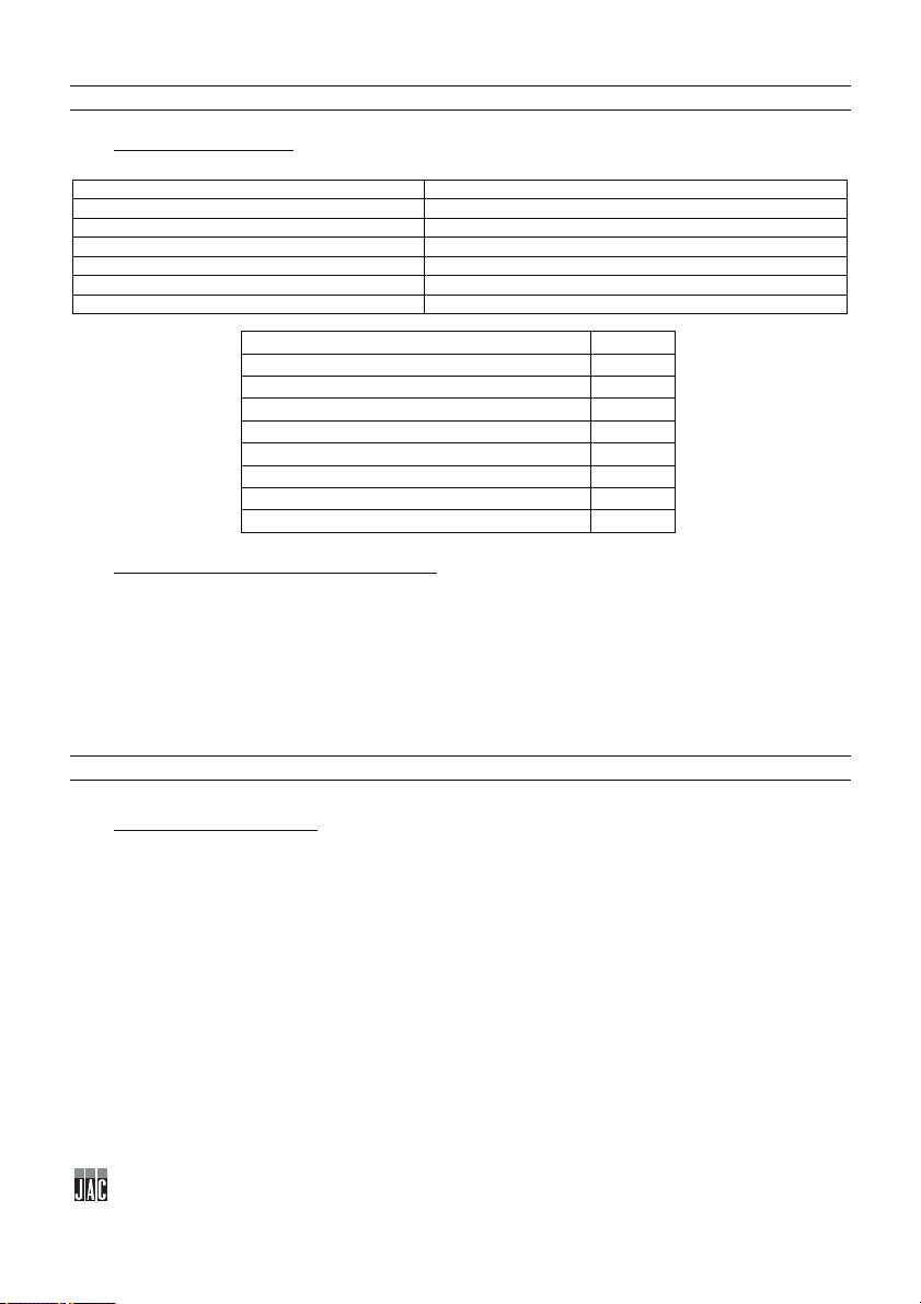
72
4 CARATTERISTICHE TECNICHE
HF
Peso minimo/massimo degli impasti in gr
50/1300
Ritmo massimo in pezzi/ora
1800
Potenza motore (kW)
00:37
Tipo di motore
Trifase
Lunghezza x larghezza x profondità
540 x 956 x 1145
Peso netto (kg)
180
Nastro estremità appuntite
opzionale
Guide d'entrata
opzionale
Nastro di uscita TRF20
opzionale
Nastro di uscita TRF30
opzionale
Base standard su rotelle
opzionale
Base con spazio portaoggetti
opzionale
Modulo pre-allungamento
Infarinatore autonomo
opzionale
Nastro di alimentazione
opzionale
4.1 Caratteristiche tecniche
4.2 Dettaglio materiali in contatto con la pasta.
Scivolo: INOX 304L.
Cilindro di laminazione: PETP alimentare bianco
Lama raschiatore: Lucoflex
Nastro di scorrimento: Maglie in acciaio inox
Nastro di allungamento: Lana / Sintetico
Nastro di allungamento fisso: Lana
Nastro di alimentazione: Tela sintetica ARCOT.
opzionale
5 INSTALLAZIONE E MESSA IN FUNZIONE
5.1 Disimballo della macchina:
Le macchine sono consegnate, franco fabbrica, su pallet, legate con cinghie e protette con pannelli di
cartone. Prima di tutto, occorre esaminare l'imballaggio e ogni danno dovuto al trasporto deve essere
dichiarato direttamente all'addetto alla consegna.
A. Togliere il cartone dalla macchina.
B. Togliere le cinghie facendo particolare attenzione allo sgancio di queste ultime durante il
taglio.
C. Staccare la macchina dal pallet.
D. Montare la macchina sui suoi piedi (Solo per il montaggio su ripiano) (fig.15, n. 24).
Italiano

73
E. Per un montaggio sulla base togliere le parti inferiori destra e sinistra per aver accesso ai
piedi, toglierle e sostituirle con le viti previste con la base (fig. 16).
Dopo il disimballo della macchina, verificare che non abbia subito danni durante il
trasporto. Segnalare ogni anomalia.
5.2 Posizionamento:
Per ottenere performance eccellenti e affidabilità a lungo termine, scegliere una posizione:
Ben ventilata, al riparo dai raggi solari diretti e lontano da fonti di calore, con una superficie
piana, robusta e priva di vibrazioni.
5.3 Collegamento elettrico:
IMPORTANTE: Messa a terra obbligatoria.
Si consiglia di proteggere l'impianto con un fusibile e un salvavita.
L'impianto elettrico che alimenta la macchina deve essere protetto secondo quanto indicato qui di
seguito:
- Nord America: Protezione 15 A;
- Resto del mondo: Protezione 16 A.
Le macchine dotate di variatore, devono necessariamente essere collegate ad una scatola di
derivazione su di una linea dotata di salvavita da 300 mA.
Nota: Ogni problema derivante da un altro tipo di collegamento non sarà preso in considerazione ai
fini della garanzia.
Prima di collegare la macchina alla rete e onde evitare una dismissione del motore all'avvio, è
importante verificare la compatibilità della rete di alimentazione con le caratteristiche della macchina
(vedere la relativa targa segnaletica).
Questo apparecchio è conforme alle direttive macchine 2006/42, 2006/95, 2004/108 e reca la
marcatura CE che attesta detta conformità.
Si invita a prendere visione della segnaletica di sicurezza che figura sulla macchina:
Segnale che indica un rischio di folgorazione. Scollegare la macchina prima di
eseguire qualsiasi intervento. Si trova sul pannello di comando che funge da
quadro elettrico (fig.9, n. 23).
All'interno del quadro elettrico si trova lo schema elettrico della macchina.
5.4 Messa in servizio:
Prima della messa in servizio, accertarsi che non vi siano oggetti estranei sulle parti in movimento
della macchina.
Accertarsi innanzitutto (dopo aver verificato le connessioni elettriche) che il motore giri nel senso
corretto. Dare impulso e verificare che il nastro della scatola anteriore proceda in alto.
Diversamente, scollegare immediatamente e invertire, nella presa, i due fili di fase.
Italiano

74
Per l’utilizzo della macchina, fare riferimento al capitolo "Utilizzo".
5.5 Pericolo:
In caso di pericolo per l'utente o per la macchina, utilizzare l'interruttore generale per interrompere
l'alimentazione della macchina.
Non avvicinarsi ai ripiani a bilanciere quando sono in movimento.
Estrarre la scheda della presa elettrica prima di ogni operazione di manutenzione o di assistenza.
Ogni operazione di manutenzione o sostituzione delle parti deve essere effettuata da un tecnico
autorizzato.
6 ORGANO DI COMANDO E DI SICUREZZA
6.1 Organo di comando:
La macchina è dotata di serie di un quadro di comando meccanico (fig. 3).
6.2 Zona di lavoro:
La zona di lavoro si trova davanti al nastro di uscita della macchina (fig.2, n. 6).
6.3 Organi di sicurezza:
Questa macchina è dotata delle seguenti sicurezze:
- Di un interruttore a leva (fig.7, n. 17) che ferma il funzionamento se si tira lo scivolo in avanti.
- Di un interruttore magnetico codificato (fig.7, n. 18) che impedisce la messa in funzione se il carter
anteriore è aperto.
- Di un pulsante di arresto d'emergenza (fig. 3, n. 7).
- Nelle versioni con Nastro di alimentazione (opzionale), di un interruttore magnetico codificato (fig.8,
n. 19) che ferma il funzionamento se si solleva il coperchio di protezione (fig.8, n. 20).
Italiano

75
7 UTILIZZO
Laminazione
Allungamento
Baguette 300g
19
11.5
Pagnotta 300g
19
15
Ciabatta 400g
18
17
Pane 520g
18
14
Pagnotta 800g
16
15
Ciabatta 1.8kg
14
12
Pagnotta 1.8Kg
16
8
Sfilatino piccolo 50g
12
15.5
P
f
Pre-regolazioni:
La tabella sopra riportata fornisce le indicazioni per effettuare le regolazioni. Tuttavia, occorre
prendere in considerazione la natura dell'impasto e la formatura che si desidera ottenere. Una
tastatura è quindi spesso necessaria ed è indispensabile tenere conto della relazione che esiste tra
ciascuna delle regolazioni.
Ad esempio, una laminazione insufficiente o un allungamento troppo serrato conferiscono all'impasto
un aspetto poco gradevole.
La laminazione si effettua con il rullo superiore (fig.3, n. 8) (Ruotare in senso orario per stringere i
rulli).
L'allungamento a laminazione si effettua con il rullo superiore (fig3, n. 8) (Ruotare in senso orario per
stringere i rulli).
Il risultato qualitativo della formatura dipende dalle regolazioni, ma anche da altri fattori quali:
- La capacità dell'impasto ad essere formato correttamente (capacità di distensione
sufficiente ma non eccessiva,
"forza" senza eccedere...).
- La forma regolare dell'impasto e la sua buona presentazione.
OSSERVAZIONE:
Affinché la formatura e l'allungamento siano eseguiti in buone condizioni, è indispensabile infarinare:
- Il nastro della vasca.
- Il nastro di allungamento.
A. Ruotare di 1/4 di giro verso destra il pulsante a fungo (arresto d'emergenza), se non è azionato (fig.
10).
B. Premere il pulsante MARCHE (MARCIA), per alimentare la macchina (fig. 11).
C. Inserire gli impasti nello scivolo protetto di ingresso (fig. 12).
D. Recuperare gli impasti formati sul nastro di recupero (fig. 13).
E. Premere il pulsante ARRET (ARRESTO), per fermare la macchina (fig. 14).
Per motivi di igiene alimentare, in nessun caso la pasta o la farina che si trovano sopra o
fuori dalla macchina devono essere riutilizzate o rimesse nella catena alimentare.
Italiano

76
8 MANUTENZIONE
8.1 Quotidiana da parte di un utilizzatore addestrato.
A fine lavoro, pulire la macchina per evitare l'accumulo di farina, che potrebbe nuocere al suo buon
funzionamento.
Togliere la protezione di scorrimento e, se necessario, spazzolare i nastri (per questa operazione
non utilizzare coppapasta metallici).
Aprire la regolazione di allungamento (fig.3, n. 12) al massimo, per facilitare l'asciugatura dei nastri
mediante la circolazione dell'aria.
In caso di umidità eccessiva, smontare l'insieme dei nastri di allungamento.
8.2 Settimanale da parte di un utilizzatore addestrato.
Estrarre e pulire i raschiatori dei cilindri di laminazione nel seguente modo:
(Operazione da effettuarsi quando la macchina non è alimentata)
A. Aprire il coperchio anteriore ed estrarlo grazie ai due blocchi (fig4, n. 14).
B. Distanziare i rulli di laminazione al massimo attraverso la manopola di regolazione (fig.3, n. 8).
C. Tirare in avanti il raschiatore laminazione fisso (fig. 5, n. 15) (se necessario staccare le molle
destra e sinistra).
D. Pulire la lama (verificare l'assenza di ogni residuo di pasta).
E. Rimontare il raschiatore ponendo ciascuna estremità nei relativi supporti, facendo attenzione a
mantenere ciascuna delle molle nella relativa sede.
F. Tirare in avanti il raschiatore laminazione regolabile (fig. 6, n. 16) (se necessario staccare le molle
destra e sinistra).
G. Pulire la lama (verificare l'assenza di ogni residuo di pasta).
H. Rimontare il raschiatore ponendo ciascuna estremità nei relativi supporti, facendo attenzione a
mantenere ciascuna delle molle nella relativa sede.
8.3 Semestrale da parte di un tecnico addestrato.
Quando la macchina è in funzione, accertarsi che non vi siano rumori anomali. Verificare anche la
corretta centratura e tensione del nastro.
Se occorre, effettuare le necessarie regolazioni.
Macchina necessariamente ferma.
Verificare lo stato e la tensione della cinghia (lubrificare se necessario).
Accertarsi del corretto funzionamento dei rulli di regolazione laminazione e allungamento.
Lubrificare le viti, se necessario.
Accertarsi del buon allineamento della vite e dei cuscinetti.
Verificare la buona condizione del nastro (semplicemente al tocco, è facile determinare se lo
spessore diventa critico).
Controllare il buono stato del nastro di allungamento.
Italiano

77
9 COMPONENTI DI CONSUMO
RIFERIMENTO
NUOVA DESCRIZIONE
MODELLO
F4505003
CURSORE VASCA WOOLTOP
TUTTE
F4505003L
CURSORE VASCA LANA
TUTTE
F5440095
NASTRO DI ALLUNGAMENTO
TUTTE
F5408011
NASTRO MAGLIA METALLICA
TUTTE
F5442003
LAMA RASCHIATORE
TUTTE
F5442007
MOLLA RASCHIATORE
DESTRA
TUTTE
F5442008
MOLLA RASCHIATORE
SINISTRA
TUTTE
F54700001
CURSORE ALIMENTAZIONE
TUTTE
F5412009L
NATRO PREALLUNGATO
TUTTE
Al momento dell'ordine di parti di ricambio, verificare con il tecnico autorizzato di quale parte si tratta
in base al catalogo delle parti di ricambio emesso dal fabbricante.
Precisare sempre il codice della macchina indicato sulla targa segnaletica.
Il tecnico effettua gli ordini presso JAC.
9.1 Elenco dei COMPONENTI DI CONSUMO
Italiano

78
10 INCIDENTI DI FUNZIONAMENTO
Problema
Verifica
La macchina non si mette in moto
Verificare gli organi di sicurezza (Pulsante arresto
anteriore).
Verificare la sicurezza del coperchio di protezione
(opzionale nastro d'alimentazione)
Il motore emette un rumore ma non parte
Verificare se manca una fase nel circuito elettrico.
I prodotti in uscita dall'allungamento sono
ATTENZIONE: Per ogni intervento, la macchina deve obbligatoriamente essere scollegata
dall'alimentazione.
Verificare l'alimentazione generale e del motore.
d'emergenza sicurezza scivolo, sicurezza coperchio
Verificare l'alimentazione del motore
strappati e non hanno un aspetto
gradevole.
Verificare la tensione del nastro.
Verificare l'aspetto e la pulizia dei raschiatori.
Verificare l'assenza di resti di pasta sul nastro.
Verificare la pulizia del feltro (Opzionale estremità
appuntite).
Verificare le regolazioni di allungamento e di
laminazione.
Se il problema persiste, contattare il proprio tecnico.
Italiano

79
11 ELENCO DEI COMPONENTI INDICATI NELLE FIGURE
Figura
Numero
Nome
1
Scivolo protetto d'ingresso
2
Nastro di ingresso
3
Ripiano di ingresso
4
Complessivo nastro pesante
5
Motorizzazione
2
6
Zona di lavoro
7
Pulsante di arresto d'emergenza
8
Regolazione laminazione
9
Segnalatore laminazione
10
Pulsante di messa in funzione
11
Pulsante di arresto
12
Regolazione dell'allungamento
13
Segnalatore dell'allungamento
4
14
Coperchio parte anteriore
5
15
Rullo raschiatore regolabile
6
16
Rullo raschiatore fisso
17
Interruttore a leva
18
Interruttore magnetico codificato
19
Interruttore magnetico codificato
Coperchio di protezione (opzionale nastro
d'alimentazione)
21
Infarinatore (Opzionale)
22
Segnale che indica un rischio di folgorazione
23
Schema elettrico
15
24
Piedi regolabili (solo su ripiano)
1
3
7
8
20
9
Italiano

80

81
نﯾﺟﻌﻟا لﯾﻛﺷﺗ تﻻآHF
1لﺑﻗ لﯾﻐﺷﺗﻟا ....................................................................................................................................... 82
2نﺎﻣﺿﻟا ........................................................................................................................................... 82
3تﺎﮭﯾﺑﻧﺗ ............................................................................................................................................ 83
4تﺎﻔﺻاوﻣﻟا ﺔﯾﻧﻔﻟا ................................................................................................................................. 84
4.1تﺎﻔﺻاوﻣﻟا ﺔﯾﻧﻔﻟا .......................................................................................................................................... 84
4.2لﯾﺻﺎﻔﺗ تﺎﻣﺎﺧﻟا ﺔﺳﻣﻼﻣﻟا لﻛﺷﺑ رﺷﺎﺑﻣ نﯾﺟﻌﻠﻟ. ........................................................................................................ 84
5بﯾﻛرﺗﻟا لﯾﻐﺷﺗﻟاو ................................................................................................................................ 84
5.1كﻓ فﯾﻠﻐﺗ ﺔﻟﻷا: ............................................................................................................................................ 84
5.2ﻊﺿوﻣﻟا: ................................................................................................................................................... 85
5.3لﯾﺻوﺗﻟا ﻲﺑرﮭﻛﻟا: ......................................................................................................................................... 85
5.4لﯾﻐﺷﺗﻟا: .................................................................................................................................................... 85
5.5رطﺧ: ....................................................................................................................................................... 86
6زﺎﮭﺟ مﻛﺣﺗﻟا نﺎﻣﻷاو ............................................................................................................................. 86
6.1زﺎﮭﺟ مﻛﺣﺗﻟا: ............................................................................................................................................... 86
6.2ﺔﻘطﻧﻣ لﻣﻋ: ................................................................................................................................................ 86
6.3ةزﮭﺟأ نﺎﻣﻷا: .............................................................................................................................................. 86
7مادﺧﺗﺳﻻا ......................................................................................................................................... 87
8ﺔﻧﺎﯾﺻﻟا ............................................................................................................................................ 87
8.1ﺔﯾﻣوﯾ ﺔطﺳاوﺑ مدﺧﺗﺳﻣ بردُﻣ. ........................................................................................................................... 87
8.2ﺔﯾﻋوﺑﺳأ ﺔطﺳاوﺑ مدﺧﺗﺳﻣ بردُﻣ. ........................................................................................................................ 88
8.3فﺻﻧ ﺔﯾوﻧﺳ ﺔﻓرﻌﻣﺑ لﯾﻛو دﻣﺗﻌﻣ. ....................................................................................................................... 88
9ﻊطﻗ تﺎﻛﻠﮭﺗﺳﻣﻟا .................................................................................................................................. 88
9.1ﺔﻣﺋﺎﻗ تﺎﻛﻠﮭﺗﺳﻣﻟﺎﺑ .......................................................................................................................................... 89
10ثادﺣﻷا ﺔﺿرﺎﻌﻟا ءﺎﻧﺛأ لﯾﻐﺷﺗﻟا ................................................................................................................. 89
11ﺔﻣﺋﺎﻗ تﺎﻧوﻛﻣﻟﺎﺑ ةدوﺟوﻣﻟا ﻲﻓ لﺎﻛﺷﻷا .......................................................................................................... 90
ﺔﯾﺳﻧرﻔﻟا ﺔﻐﻠﻟا

82
ﺔﯾﺳﻧرﻔﻟا ﺔﻐﻠﻟا
لوﻠﺣ مﻛرﺎﯾﺗﺧﻻ مﻛرﻛﺷﻧJAC بﻧﺟﺗﺗو كﺳﻔﻧ ﻲﻣﺣﺗ نأ كﻧﻛﻣﯾ .ﺔﻟﻵا هذھ لﯾﻐﺷﺗو بﯾﻛرﺗ لﺑﻗ اذھ مادﺧﺗﺳﻻا لﯾﻟد ةءارﻗ نﻣ دﻛﺄﺗ .
.ﺔﻟﻵا فﻠﺗﺗ نأ اذﻛھ
ﺎﮭﯾﻟإ عوﺟرﻟا ﻰﺟرُﯾ .لﯾﻟدﻟا اذھ ﺔﯾﺎﮭﻧ ﻲﻓ ةدوﺟوﻣ لﺎﻛﺷﻷا هذھ .تﺎﻣﯾﻠﻌﺗﻟا مﮭﻓ لﯾﮭﺳﺗ لﺟأ نﻣ ﺔﻔﻠﺗﺧﻣ لﺎﻛﺷأ ﻰﻟإ لﯾﻟدﻟا اذھ رﯾﺷﯾ
ﻟﺎﺗﻟا زوﻣرﻟا ىرﺗ نإ ﺎﻣ.(اذﻛ مﻗرو ،اذﻛ لﻛﺷ) ﺔﯾ
:ﺔﯾﻟﺎﺗﻟا ﺢﺋﺎﺻﻧﻟا ﻰﻠﻋ عﻼطﻻا ﻰﻟإ كوﻋدﻧ ،ﺔﻣدﺎﻘﻟا تاوﻧﺳﻟا لﻼﺧ ﺔﻟﻵا هذھ ءادأ نﻋ ﺎًﻣﺎﻣﺗ ﺎًﯾﺿار نوﻛﺗ نأ لﺟأ نﻣ
.ﺔﻟﻵا فﻠﺧ ﺔﻧﺎﯾﺻﻟا رﺗﻓد دﺟوﯾ .ﺔﻟﻵا بﯾﻛرﺗ ءﺎﻧﺛأ
ﺔﻛرﺷ مدﻘﺗJAC ﮫﺗدﻣ ﺎﮭﺗﺎﺟﺗﻧﻣ لﻛ ﻰﻠﻋ ﺎًﻧﺎﻣﺿ5 .تاوﻧﺳ
ﺦﯾرﺎﺗ نﻣ نﺎﻣﺿﻟا يرﺳﯾ .تﺎﻛﻠﮭﺗﺳﻣﻟا نود ،ﺔﯾﻧورﺗﻛﻟﻹا ﻊطﻘﻟا ﺎﮭﯾﻓ ﺎﻣﺑ ،ﺔﻟﻵا ﻊطﻗ لﻛ ﻰﻠﻋ نﺎﻣﺿﻟا اذھ يرﺳﯾ.ةدﻌُﻣﻟا بﯾﻛرﺗ
:ﺔﯾﻟﺎﺗﻟا ةدﯾﻘﻣﻟا طورﺷﻟا بﺳﺣﺑ
.(مدﺧﺗﺳﻣﻟا
نﺎﻣﺿﻟا ةرﺗﻓ رﺻﺗﻘﺗ ،ﺢﯾﺣﺻ لﻛﺷﺑ لﻣﺗﻛﻣ رﯾﻏ ﺔﻧﺎﯾﺻﻟا رﺗﻓد نأ وأ/و دﻣﺗﻌﻣ لﯾﻛو نﻣ ﺔﻧﺎﯾﺻ دﺟوﺗ مﻟ اذإ.ةدﺣاو مﺎﻋ ﻰﻠﻋ
:لﻣﺷﯾ ﻻ نﺎﻣﺿﻟا نﺄﺑ ﺎًﻣﻠﻋ
.نﺎﻣﺿﻟا اذھ ددﻣﯾ نأ نﺎﻣﺿﻟا ةدﻣ لﻼﺧ مﺗﯾ يذﻟا ﺔﻔﻟﺎﺗﻟا رﺎﯾﻐﻟا ﻊطﻘﻟ لادﺑﺗﺳﻻا وأ/و حﻼﺻﻹا نﺄﺷ نﻣ سﯾﻟ
1
لﯾﻐﺷﺗﻟا لﺑﻗ
- .ﺔﻌﺑﺎﺗﻣﻟاو لﯾﻐﺷﺗﻟاو بﯾﻛرﺗﻟا لﺟأ نﻣ دﻣﺗﻌﻣ لﯾﻛوﺑ نﻌﺗﺳا
- ﮫﺗدﻣو نﺎﻣﺿﻟا نﻣ ةدﺎﻔﺗﺳﻻا لﺟأ نﻣ5 ةروﻛذﻣﻟا طورﺷﻟا رظﻧا) تاوﻧﺳ ﺔﻧﺎﯾﺻﻟا رﺗﻓد لﺎﻣﻛﺗﺳﺎﺑ ،عزوﻣﻟا ﺔطﺳاوﺑ مﻗ ،(دﻌﺑ
2 نﺎﻣﺿﻟا
- ؛دﻣﺗﻌﻣ عزوﻣ نﻣ ةدﻌُﻣﻟا ءارﺷ مﺗ
- ؛دﻣﺗﻌﻣ لﯾﻛو ﺔﻓرﻌﻣﺑ بﯾﻛرﺗﻟا مﺗ
- ؛ﮫﻠﺟأ نﻣ تﻌﻧُﺻ يذﻟا ضرﻐﻟا ﻲﻓو مادﺧﺗﺳﻻا لﯾﻟد تﺎﻣﯾﻠﻌﺗﻟ ﺎًﻘﻓو ةدﻌُﻣﻟا مادﺧﺗﺳا
- ؛مادﺧﺗﺳﻻا لﯾﻟد تادﺎﺷرﻹ ﺎًﻘﻓو ﺎًﯾﻣوﯾ ةدﻌُﻣﻟا ﺔﻧﺎﯾﺻ مﺗﯾ
- ﻟا ﻊﺑﺎﺗﯾ بﺎﺳﺣ ﻰﻠﻋ ﺔﻧﺎﯾﺻﻟا) لﻗﻷا ﻰﻠﻋ ،مﺎﻌﻟا ﻲﻓ ةرﻣ ﺔﻧﺎﯾﺻﻟا ءارﺟإ ﻊﻣ ،ﺔﻧﺎﯾﺻﻟا طورﺷﻟ ﺎًﻘﻓو دﻣﺗﻌﻣﻟا لﯾﻛوﻟا ﺔﻧﺎﯾﺻ
- نﻣ ﺔﯾﻠﺻﻷا رﺎﯾﻐﻟا ﻊطﻘﻟ يرﺻﺣﻟا مادﺧﺗﺳﻻاJAC.
- ةرﻘﻓ) تﺎﻛﻠﮭﺗﺳﻣﻟا لادﺑﺗﺳا9؛(
- ؛ﺔﻔﻟﺎﺗ ﺎﮭﻧﺄﺑ ﺔﯾﻧﻔﻟا ﺔﻣدﺧﻟا مﺳﻗ رﻘﯾ مﻟ ﻲﺗﻟا رﺎﯾﻐﻟا ﻊطﻗ
- ؛ةدﻌُﻣﻠﻟ مﯾﻠﺳﻟا رﯾﻏ مادﺧﺗﺳﻻا نﻋ ﺔﻣﺟﺎﻧﻟا تﻼﻛﺷﻣﻟا
- ؛دﻣﺗﻌﻣ لﯾﻛو ﺔﻓرﻌﻣﺑ مﺗﯾ مﻟ بﯾﻛرﺗ نﻋ ﺔﻣﺟﺎﻧﻟا تﻼﻛﺷﻣﻟا
- ﻛﺷﻣﻟا وأ رﺎﯾﻐﻟا ﻊطﻗ.ﺔﺑﺳﺎﻧﻣﻟا رﯾﻏ ﺔﻟوﺎﻧﻣﻟا وأ لﻘﻧﻟا ءﺎﻧﺛأ فﻠﺗ نﻋ ﺔﻣﺟﺎﻧﻟا تﻼ
ﺔﯾﺳﻧرﻔﻟا ﺔﻐﻠﻟا

83
3 تﺎﮭﯾﺑﻧﺗ
مﺗﯾﺳ نﺎﻛ اذإ .لﺑﻘﺗﺳﻣﻟا ﻲﻓ ﮫﯾﻠﻋ عﻼطﻼﻟ زﺎﮭﺟﻟا ﻊﻣ اذھ مادﺧﺗﺳﻻا لﯾﻟد ظﻔﺣ اًدﺟ مﮭﻣﻟا نﻣ ءﺎطﻋإ مﺗﯾ نأ دﻛﺄﺗﻓ ،رﺧآ صﺧﺷ ﻰﻟإ زﺎﮭﺟﻟا اذھ لﻘﻧ وأ ﻊﯾﺑ
.زﺎﮭﺟﻟا مادﺧﺗﺳاو بﯾﻛرﺗ لﺑﻗ هﺎﺑﺗﻧﺎﺑ ﺎﮭﺗءارﻗ ءﺎﺟرﻟا .نﯾرﺧﻵا ﺔﻣﻼﺳ ﻰﻠﻋو كﺗﻣﻼﺳ ﻰﻠﻋ ﺎًﺻرﺣ تﺎﮭﯾﺑﻧﺗﻟا هذھ ءﺎطﻋإ مﺗ
.ﺔﻧﺎﯾﺻﻟا تﺎﯾﻠﻣﻋ لﺑﻗو زﺎﮭﺟﻠﻟ ﻲﺟرﺎﺧﻟا/ﻲﻠﺧادﻟا فﯾظﻧﺗﻟﺎﺑ مﺎﯾ
.ﮫﺑ ﺔﻘﻠﻌﺗﻣﻟا تﺎﮭﯾﺑﻧﺗﻟاو ﮫﻠﯾﻐﺷﺗ ﺔﻓرﻌﻣ مدﺧﺗﺳﻣﻟا ﻊﯾطﺗﺳﯾ ثﯾﺣﺑ اذھ مادﺧﺗﺳﻻا لﯾﻟد
.ﻲﻧﮭﻣﻟا مادﺧﺗﺳﻼﻟ ﺎًﯾرﺻﺣ ﺔﺻﺻﺧﻣ ﺔﻟﻵا هذھ
.ﺔﻟﻷا هذھ تﺎﻔﺻاوﻣ لﯾدﻌﺗ ﺔﻟوﺎﺣﻣ وأ لﯾدﻌﺗ رطﺧﻟا نﻣ
.ءﺎﺑرﮭﻛ لﺑﺎﻛ ﻰﻠﻋ دﻧﺗﺳﺗ ﻻ ﺎﮭﻧأ دﻛﺄﺗ ،ﺔﻟﻵا بﯾﻛرﺗ دﻌﺑ
.ةرارﺣﻟاو ﺔﺑوطرﻟا نﻋ دﯾﻌﺑ نﺎﻛﻣ لﺧاد ﺔﻟﻵا هذھ مادﺧﺗﺳاو نﯾزﺧﺗ بﺟﯾ
.لﻣﻌﻟﺎﺑ مﺎﯾﻘﻠﻟ ﺔﻟﻵا هذﮭﻟ ﺔﯾﻓﺎﻛ ةءﺎﺿإ كﺎﻧھ نوﻛﯾ نأ بﺟﯾ
EN ISO 3744.
وﺎﻧﻣ ءﺎﻧﺛأ نﺎﻣﻷا تﺎطﺎﯾﺗﺣا لﻛ ذﺧﺗا .نزوﻟا لﯾﻘﺛ زﺎﮭﺟﻟا اذھ
.ﮫﺗﻟ
نﻣ لﻗأ ﺔﻟﻷا هذھ توﺻ ىوﺗﺳﻣ75 رﺎﯾﻌﻣﻠﻟ ﺎًﻘﻓو لﺑﯾﺳﯾد
دﺣاو صﺧﺷ ﺔﻟﻵا هذھ مدﺧﺗﺳﯾ نأ بﺟﯾ .(ﺔﻔﻟﺎﺧﻣ تﺎﻣﯾﻠﻌﺗ دﺟوﯾ مﻟ ﺎﻣ) دﺣاوﻟا تﻗوﻟا ﻲﻓ
ﻘﻟا لﺑﻗ ﻲﺑرﮭﻛﻟا رﺎﯾﺗﻟا ﺎًﻣﺋاد لﺻﻓا
ذھ مﯾﻣﺻﺗ مﺗ.ﺔﺑﻌﻠﻛ ﺎھوﻣدﺧﺗﺳﯾ نأ وأ لﺎﻔطﻷا ﺎﮭﺳﻣﻠﯾ ﻻأ ﻰﺟرﯾ .ﺎﮭﻣادﺧﺗﺳﺎﺑ مﮭﻟ حوﻣﺳﻣ نوﻐﻟﺎﺑ صﺎﺧﺷأ ﺎﮭﻣدﺧﺗﺳﯾ ﻲﻛﻟ ﺔﻟﻵا ه
ﻊﺑﺗا.مادﺧﺗﺳﻻا لﺟأ نﻣ ةﺎطﻌﻣﻟا تﺎﻣﯾﻠﻌﺗﻟا
ﺔﯾﺳﻧرﻔﻟا ﺔﻐﻠﻟا

84
4 ﺔﯾﻧﻔﻟا تﺎﻔﺻاوﻣﻟا
HF
مارﺟﻟﺎﺑ نﯾﺟﻌﻟا ﻊطﻘﻟ نزو ﻰﺻﻗأ/لﻗأ
50 /1300
ﺔﻋﺎﺳ/ﺔﻌطﻗ ﻊطﻘﻟﺎﺑ لدﻌﻣﻟا ﻰﺻﻗأ
1800
(طاو وﻠﯾﻛ) روﺗوﻣﻟا ةوﻗ
.37
روﺗوﻣﻟا عوﻧ
) راوطﻷا ﻲﺛﻼﺛ3 (ةزﺎﻓ
عﺎﻔﺗرا × ضرﻋ ×قﻣﻋ
540 ×956 ×1145
(مﺟﻛ) ﻲﻓﺎﺻﻟا نزوﻟا
180
ﺔﺑﺑدﻣ فارطﺄﺑ طﺎﺳُﺑ
يرﺎﯾﺗﺧا
لﺎﺧدﻹا ﺔﻟدأ
يرﺎﯾﺗﺧا
جارﺧﻹا طﺎﺳﺑTRF20
يرﺎﯾﺗﺧا
جارﺧﻹا طﺎﺳﺑTRF30
يرﺎﯾﺗﺧا
لﺟﻋ ﻰﻠﻋ ﺔﯾﺳﺎﯾﻗ ةدﻋﺎﻗ
يرﺎﯾﺗﺧا
نﯾزﺧﺗ ﻊﻣ ةدﻋﺎﻗ
يرﺎﯾﺗﺧا
ﺔﻘﺑﺳُﻣ ﺔﻟﺎطﺗﺳا لوﯾدوﻣ
يرﺎﯾﺗﺧا
ﺔﻠﻘﺗﺳﻣ قﯾﻗد ﺔﺿﻔﻧﻣ
يرﺎﯾﺗﺧا
ﺔﯾذﻐﺗ طﺎﺳُﺑ
يرﺎﯾﺗﺧا
4.1 ﺔﯾﻧﻔﻟا تﺎﻔﺻاوﻣﻟا
4.2 لﯾﺻﺎﻔﺗ رﺷﺎﺑﻣ لﻛﺷﺑ ﺔﺳﻣﻼﻣﻟا تﺎﻣﺎﺧﻟا.نﯾﺟﻌﻠﻟ
:بازﯾﻣ أدﺻﻠﻟ موﺎﻘﻣ ذﻻوﻓ304L
:قﯾﻗرﺗ ﺔﻧاوطﺳأ ضﯾﺑأ ﻲﺋاذﻏ تﻻﺎﺛﻓرﯾﺗ نﯾﻠﯾﺛﯾإ ﻲﻟوﺑ
:طﺷﺎﻘﻟا ةرﻔﺷ Lucoflex
:كﯾرﺣﺗﻟا طﺎﺳُﺑأدﺻﻠﻟ موﺎﻘﻣﻟا بﻠﺻﻟا نﻣ ﺔﻛﺑﺷ
:ﺔﻟﺎطﻹاو درﻔﻟا طﺎﺳُﺑ ﺔﯾﻋﺎﻧﺻ فﺎﯾﻟأ / فوﺻ
:تﺑﺎﺛﻟا درﻔﻟا طﺎﺳُﺑ فوﺻﻟا
:دادﻣإ طﺎﺳُﺑ ﻲﻋﺎﻧﺻ ﺞﯾﺳﻧARCOT.
غﻼﺑإو ةوﺑﻌﻟا صﺣﻓ بﺟﯾ ،ءﻲﺷ يﺄﺑ مﺎﯾﻘﻟا لﺑﻗ .نوﺗرﻛﻟا قروﺑ ﺔﯾﻣﺣﻣو ﺔطرﺷﺄﺑ ﺔطوﺑرﻣو ،حاوﻟأ ﻰﻠﻋ ،ﺎﻧﺷرو نﻣ ﺎﮭﺟورﺧ دﻧﻋ ،تﻻﻵا عﺎﺑُﺗ
.لﻘﻧﻟا نﻋ ﺢﺗﺎﻧ فﻠﺗ يﺄﺑ ةرﺷﺎﺑﻣ لﯾﺻوﺗﻟا ﺔﻛرﺷ
ﺔﯾﺳﻧرﻔﻟا ﺔﻐﻠﻟا
5 لﯾﻐﺷﺗﻟاو بﯾﻛرﺗﻟا
5.1 :ﺔﻟﻷا فﯾﻠﻐﺗ كﻓ
A. .ﺔﻟﻵا ﺔﻧوﺗرﻛ بﺣﺳا
B. لﻛﺷﺑ هﺎﺑﺗﻧﻻا ﻊﻣ ﺔطرﺷﻷا عزﻧا.ﺎﮭﻌطﻗ ءﺎﻧﺛأ ةرﯾﺧﻷا هذھ ءﺎﺧﺗرا ﻰﻟإ صﺎﺧ
C. .حوﻠﻟا نﻋ ﺔﻟﻵا لزﻧأ
D. ) (طﻘﻓ ةدﺿﻧﻣ ﻰﻠﻋ بﯾﻛرﺗﻟا صﺧﯾ) مﺋاوﻘﻟا ﻰﻠﻋ ﺔﻟﻵا بﻛرfig.15, n°24.(

85
ﻲﻏارﺑﻟﺎﺑ ﺎﮭﻟدﺑﺗﺳاو ﺎﮭﺑﺣﺳاو ،مﺋاوﻘﻟا ﻰﻟإ لوﺻوﻟا لﺟأ نﻣ ىرﺳﯾﻟاو ﻰﻧﻣﯾﻟا ﺔﯾﻠﻔﺳﻟا باوﺑﻷا عزﻧا ،ةدﻋﺎﻗ ﻰﻠﻋ بﯾﻛرﺗﻠﻟ ﺔﺑﺳﻧﻟﺎﺑ .ـھ
ﺧﻣﻟا) ةدﻋﺎﻘﻟا ﻊﻣ ضرﻐﻟا اذﮭﻟ ﺔﺻﺻfig16(
.بطﻋ يﺄﺑ ﺎﻧﻐﻠﺑأو .لﻘﻧﻟا ءﺎﻧﺛأ فﻠﺗﻠﻟ ضرﻌﺗﺗ مﻟ ﺎﮭﻧأ قﻘﺣﺗ ،نوﺗرﻛﻟا نﻣ ﺔﻟﻵا جارﺧإ دﻌﺑ
:ﺎًﻌﺿوﻣ رﺗﺧا ،لﯾوطﻟا ىدﻣﻟا ﻰﻠﻋ ﺔﯾﻟﺎﻌﻓو زﺎﺗﻣﻣ ءادأ ﻰﻠﻋ لوﺻﺣﻠﻟ
ردﺎﺻﻣ نﻋ اًدﯾﻌﺑو ةرﺷﺎﺑﻣﻟا سﻣﺷﻟا ﺔﻌﺷأ نﻋ اًدﯾﻌﺑو ،ﺔﯾوﮭﺗﻟا دﯾﺟ.تازازﺗھﻻا نﻣ ٍلﺎﺧو يوﻗو وﺗﺳﻣ ﺢطﺳ ﻊﻣ ةرارﺣﻟا
.ﻲﻠﺿﺎﻔﺗ رﺎﯾﺗ ﻊطﺎﻗو رﮭﺻﻧﻣﺑ ﺔﯾﺑرﮭﻛﻟا تادﯾدﻣﺗﻟا ﺔﯾﺎﻣﺣﺑ ﺢﺻﻧُﯾ
:هﺎﻧدأ نﯾﺑُﻣ وھ ﺎﻣﻛ ﺔﻟﻵا يذﻐُﺗ ﻲﺗﻟا ﺔﯾﺑرﮭﻛﻟا تادﯾدﻣﺗﻟا ﺔﯾﺎﻣﺣ بﺟﯾ
ﺔﯾﺎﻣﺣ :مﻟﺎﻌﻟا لود ﺔﯾﻘﺑ16 .رﯾﺑﻣأ
ﻲﻠﺿﺎﻔﺗ رﺎﯾﺗ ﻊطﺎﻘﺑ زﮭﺟﻣ طﺧ ﻰﻠﻋ ﻎﯾرﻔﺗﻟا ﺔﺑﻠُﻋ ﻰﻠﻋ ﮫﻠﯾﺻوﺗ بﺟﯾ ،ﻲﺋﺎﺑرﮭﻛ رّﯾﻐُﻣﺑ ةزﮭﺟﻣﻟا تﻻﻶﻟ ﺔﺑﺳﻧﻟﺎﺑ300 .رﯾﺑﻣأ ﻲﻠﻣ
.نﺎﻣﺿﻟا ﺎﮭﻠﻣﺷﯾ نﻟ رﺧآ لﻛﺷﺑ لﯾﺻوﺗﻟا نﻋ ﺔﻣﺟﺎﻧ ﺔﻠﻛﺷﻣ يأ :ﺔظوﺣﻠﻣ
ﺟﺗ لﺟأ نﻣو ءﺎﺑرﮭﻛﻟا ﺔﻛﺑﺷ ﻰﻠﻋ ﺔﻟﻵا لﯾﺻوﺗ لﺑﻗ ءﺎﺑرﮭﻛﻟا ﺔﻛﺑﺷ قﻓاوﺗ نﻣ قﻘﺣﺗﻟا مﮭﻣﻟا نﻣ ،ءﺎﺑرﮭﻛﻟﺎﺑ ﮫﻠﯾﺻوﺗ دﻧﻋ روﺗوﻣﻟا لﯾﻐﺷﺗ فﻗو بﻧ
.(ﺔﻟﻵا هذﮭﻟ تﺎﻧﺎﯾﺑﻟا ﺔﺣوﻟ رظﻧا) ﺔﻟﻵا تﺎﻔﺻاوﻣ ﻊﻣ
تﻻﻵﺎﺑ ﺔﺻﺎﺧﻟا تﺎﻣﯾﻠﻌﺗﻟا ﻊﻣ زﺎﮭﺟﻟا اذھ قﻓاوﺗﯾ2006/42 و2006/95 و2004/108 ﺔﻣﻼﻋ لﻣﺣﯾوCE .كﻟذﺑ دﮭﺷﺗ ﻲﺗﻟا
ﻰﻠﻋ عﻼطﻻا ﻰﺟرﯾ :ﺔﻟﻵا ﻰﻠﻋ ةدوﺟوﻣﻟا نﺎﻣﻷﺎﺑ ﺔﻘﻠﻌﺗﻣﻟا ﺔﯾﺣﯾﺿوﺗﻟا روﺻﻟا
ﻰﻠﻋ هدﺟﺗ نأ كﻧﻛﻣﯾ .ﺎﮭﻟ حﻼﺻإ يأ لﺑﻗ ﺔﻧﯾﻛﺎﻣﻟا لﺻﻓ ﻰﺟرُﯾ .ءﺎﺑرﮭﻛﻟﺎﺑ قﻌﺻﻟا رطﺧ ﻰﻟإ رﯾﺷُﺗ ﺔﯾﺣﯾﺿوﺗ ةروﺻ
) .ﻲﺑرﮭﻛﻟا قودﻧﺻﻟا لﺣﻣ لﺣﺗ ﻲﺗﻟا مﻛﺣﺗﻟا ﺔﺣوﻟfig.9, n°23(
لﺧاد ﺔﻟﻶﻟ ﻲﺑرﮭﻛﻟا ﻲطﯾطﺧﺗﻟا مﺳرﻟا دﺟﺗ فوﺳ) ﻲﺑرﮭﻛﻟا قودﻧﺻﻟاfig.9, n°23.(
.ﺔﻟﻶﻟ ﺔﻛرﺣﺗﻣﻟا ءازﺟﻷا ﻰﻠﻋ لﯾﺧد ءﻲﺷ يأ دوﺟو مدﻋ نﻣ دﻛﺄﺗ ،لﯾﻐﺷﺗﻟا لﺑﻗ
طﺎﺳُﺑ نأ نﻣ قﻘﺣﺗو لﯾﻐﺷﺗ ﺔﻌﻓد ِطﻋأ ،كﻟذﺑ مﺎﯾﻘﻠﻟ .ﺢﯾﺣﺻﻟا هﺎﺟﺗﻻا ﻲﻓ رودﯾ روﺗوﻣﻟا نأ (ﻲﺑرﮭﻛﻟا قﻓاوﺗﻟا نﻣ قﻘﺣﺗﻟا دﻌﺑ) ًﻻوأ دﻛﺄﺗ قودﻧﺻﻟا
.سﺑﺎﻘﻟا ﻲﻓ ةزﺎﻔﻟا ﻲﻓرط سﻛﻋاو روﻔﻟا ﻰﻠﻋ ءﺎﺑرﮭﻛﻟا لﺻﻓﺎﻓ ،كﻟذﻛ لﺎﺣﻟا نﻛﯾ مﻟ اذإ
."مادﺧﺗﺳﻻا" لﺻﻓ ﻊﺟار ،ﺔﻟﻵا مادﺧﺗﺳﻻ
5.2 :ﻊﺿوﻣﻟا
5.3 :ﻲﺑرﮭﻛﻟا لﯾﺻوﺗﻟا
مﺎھ.ﻲﻣازﻟإ ﻲﺿرﻷا فرطﻟا لﯾﺻوﺗ :
- ﺔﯾﺎﻣﺣ :ﺔﯾﻟﺎﻣﺷﻟا ﺎﻛﯾرﻣأ15 رﯾﺑﻣأ؛
5.4 :لﯾﻐﺷﺗﻟا
ﺗﯾ ﻲﻣﺎﻣﻷا.ﻰﻠﻋأ ﻰﻟإ ﮫﺟ
ﺔﯾﺳﻧرﻔﻟا ﺔﻐﻠﻟا

86
5.5 :رطﺧ
.ﺔﻟﻵا نﻋ ﻲﺑرﮭﻛﻟا رﺎﯾﺗﻟا لﺻﻔﻟ ﻲﻣوﻣﻌﻟا ﻊطﻘﻟا حﺎﺗﻔﻣ مدﺧﺗﺳﺗ نأ كﯾﻠﻋ بﺟﯾ ،ﺔﻟﻵا ﻰﻠﻋ وأ مدﺧﺗﺳﻣﻟا ﻰﻠﻋ رطﺧ دوﺟو ﺔﻟﺎﺣ ﻲﻓ
.كرﺣﺗﺗ ﺎﻣدﻧﻋ ﺢﺟرﺄﺗﻟا ﻲﻧاوﺻ نﻣ برﺗﻘﺗ ﻻ
.صﺣﻓ وأ ﺔﻧﺎﯾﺻ ﺔﯾﻠﻣﻋ ﺔﯾﺄﺑ مﺎﯾﻘﻟا لﺑﻗ ﻲﺑرﮭﻛﻟا سﺑﻘﻣﻟا نﻣ سﺑﺎﻘﻟا بﺣﺳا
.دﻣﺗﻌﻣ لﯾﻛو ﺔطﺳاوﺑ مﺗﺗ نأ بﺟﯾ رﺎﯾﻏ ﺔﻌطﻗ لادﺑﺗﺳا وأ ﺔﻧﺎﯾﺻ ﺔﯾﻠﻣﻋ يأ
6 نﺎﻣﻷاو مﻛﺣﺗﻟا زﺎﮭﺟ
6.1 :مﻛﺣﺗﻟا زﺎﮭﺟ
) ﺔﯾﻛﯾﻧﺎﻛﯾﻣ رارزأ ﺔﺣوﻠﺑ ﻲﻟاوﺗﻟا ﻰﻠﻋ ةزﮭﺟﻣ ﺔﻟﻵاfig. 3.(
6.2 :لﻣﻋ ﺔﻘطﻧﻣ
) ﺔﻟﻵا ﻲﻓ جارﺧﻹا طﺎﺳُﺑ مﺎﻣأ لﻣﻌﻟا ﺔﻘطﻧﻣ دﺟوﺗfig.2, n°6.(
6.3 :نﺎﻣﻷا ةزﮭﺟأ
:نﺎﻣأ ﺔﻣظﻧﺄﺑ ةزﮭﺟﻣ ﺔﻟﻵا هذھ
) ﺔﯾﺎﻣﺣﻟا ءﺎطﻏfig.8, n°20.(
- ) عارذﺑ رﺎﯾﺗ ﻊطﺎﻗfig.7, n°17.مﺎﻣﻸﻟ نازﯾﻣﻟا ﺎﻧﺑذﺟ اذإ لﯾﻐﺷﺗﻟا فﻗوﺗ (
- ) رﻔﺷﻣ ﻲﺳﯾطﺎﻧﻐﻣ رﺎﯾﺗ ﻊطﺎﻗfig.7, n°18ا نﺎﻛ اذإ لﯾﻐﺷﺗﻟا ﻊﻧﻣﯾ (.ﺎًﺣوﺗﻔﻣ ﻲﻣﺎﻣﻷا ضوﺣﻟ
- ) ئراوطﻟا ﺔﻟﺎﺣ ﻲﻓ فﺎﻘﯾإ رزfig.3, n°7.(
- ) رﻔﺷُﻣ ﻲﺳﯾطﺎﻧﻐﻣ رﺎﯾﺗ ﻊطﺎﻗ دﺟوﯾ ،(يرﺎﯾﺗﺧا) ﺔﯾذﻐﺗ طﺎﺳُﺑ ﺎﮭﺑ ﻲﺗﻟا تﻻﻵا نﻣ تارادﺻﻺﻟ ﺔﺑﺳﻧﻟﺎﺑfig.8, n°19 ﺎﻧﻌﻓر اذإ لﯾﻐﺷﺗﻟا فﻗوﯾ (
ﺔﯾﺳﻧرﻔﻟا ﺔﻐﻠﻟا

87
7 مادﺧﺗﺳﻻا
قﯾﻗرﺗ
لﯾوطﺗ
لﯾوط فﯾﻏر300 مﺟ
19
11.5
رﯾﺻﻗ300 مﺟ
19
15
لﯾوط زﺑﺧ400 مﺟ
18
17
زﺑﺧ فﯾﻏر520 مﺟ
18
14
رﯾﺻﻗ زﺑﺧ800 مﺟ
16
15
لﯾوط زﺑﺧ1.8 مﺟﻛ
14
12
رﯾﺻﻗ زﺑﺧ1.8 مﺟﻛ
16
8
لﯾوط رزﯾﺎﻛ فﯾﻏر50 مﺟ
12
15.5
:قﺑﺳﻣﻟا طﺑﺿﻟا
.طﺑﺿ ةرﻣ لﻛ نﯾﺑ دﺟوﺗ ﻲﺗﻟا ﺔﻗﻼﻌﻟا نﺎﺑﺳﺣﻟا ﻲﻓ ذﺧﻷا يرورﺿﻟا نﻣو ﺎًﻣزﻻ
ﻗ ﻲطﻌﯾ اًدﺟ قﯾﺿﻟا لﯾوطﺗﻟا وأ ﻲﻓﺎﻛﻟا رﯾﻏ قﯾﻗرﺗﻟا ،لﺎﺛﻣﻟا لﯾﺑﺳ ﻰﻠﻋ.لﻛﺷﻟا ﺔﺋﯾﺳ نﯾﺟﻋ ﺔﻌط
) يوﻠﻌﻟا سرﺗﻟا مادﺧﺗﺳﺎﺑ قﯾﻗرﺗﻟا مﺗﯾfig.3, n°8.(تﺎﻧاوطﺳﻷا دﺷﯾ ﺔﻋﺎﺳﻟا برﺎﻘﻋ هﺎﺟﺗا ﻲﻓ نارودﻟا) (
) ﻲﻠﻔﺳﻟا سرﺗﻟا مادﺧﺗﺳﺎﺑ لﯾوطﺗﻟا مﺗﯾfig.3, n°12.(لﯾوطﺗﻟا حوﻟ دﺷﯾ ﺔﻋﺎﺳﻟا برﺎﻘﻋ هﺎﺟﺗا ﻲﻓ نارودﻟا) (
ﻲطﻌﯾ سﺳﺣﺗﻟا نوﻛﯾ ﻲﻟﺎﺗﻟﺎﺑو .بوﻠطﻣﻟا لﯾﻛﺷﺗﻟاو نﯾﺟﻌﻟا ﺔﻌﯾﺑط نﺎﺑﺳﺣﻟا ﻲﻓ ﻊﺿﻧ نأ نﻣ دﺑ ﻻ ﮫﻧأ رﯾﻏ .طﺑﺿﻟﺎﺑ مﺎﯾﻘﻠﻟ تﺎﻧﺎﯾﺑ هﻼﻋأ لودﺟﻟا
:ﺔﺟﯾﺗﻧ ﺎًﺿﯾأ نﻛﻟو طﺑﺿﻠﻟ ﺎًﻘﻓو لﯾﻛﺷﺗﻟا ﺔﺟﯾﺗﻧ نوﻛﺗ
:ﻰﻠﻋ قﯾﻗدﻟا رﺛﻧ يرورﺿﻟا نﻣ ،ةدﯾﺟ فورظ ﻲﻓ لﯾوطﺗﻟاو لﯾﻛﺷﺗﻟا مﺗﯾ نأ لﺟأ نﻣ
فﺎﻘﯾإ) يروﻔﻟا فﺎﻘﯾﻹا رز فﻠﺑ مﻗ .أ ) ﮫﻠﯾﻐﺷﺗ مﺗ دﻗ نﻛﯾ مﻟ اذإ ،نﯾﻣﯾﻟا وﺣﻧ ﺔﻔﻟ ﻊﺑر (ئراوطﻟاfig.10.(
لﯾﻐﺷﺗﻟا رزﻟا ﻰﻠﻋ طﻐﺿا .بMARCHE) ﺔﻟﻶﻟ ءﺎﺑرﮭﻛﻟا لﯾﺻوﺗ لﺟأ نﻣ ،fig.11.(
) نّﻣؤﻣﻟا لﺎﺧدﻹا بازﯾﻣ ﻲﻓ نﯾﺟﻌﻟا ﻊطﻗ لﺧدأ .جfig.12 .(
) لﺎﺑﻘﺗﺳﻻا طﺎﺳُﺑ ﻰﻠﻋ ﺔﻠﻛﺷُﻣ نﯾﺟﻌﻟا ﻊطﻗ دﻌﺗﺳا .دfig.13 .(
فﺎﻘﯾﻹا رزﻟا ﻰﻠﻋ طﻐﺿا .ـھARRET ) ﺔﻟﻵا فﺎﻘﯾإ لﺟأ نﻣfig.14.(
ﻲﻓ ﮫﻌﺿو ةدﺎﻋإ ﻻو ﺎﮭﺟرﺎﺧ وأ ﺔﻟﻵا ﻰﻠﻋأ دوﺟوﻣﻟا قﯾﻗدﻟا وأ نﯾﺟﻌﻟا مادﺧﺗﺳا ةدﺎﻋإ ﺎًﺗﺎﺗﺑ بﺟﯾ ﻻ ،ءاذﻐﻟا ﺔﻣﻼﺳﺑ قﻠﻌﺗﺗ بﺎﺑﺳﻷ
ﺔﯾﺋاذﻐﻟا ﺔﻠﺳﻠﺳﻟا
) ةﺎﺷرﻔﻟﺎﺑ طﺎﺳُﺑﻟا فﯾظﻧﺗﺑ مﻘﻓ ،رﻣﻷا مزﻟ اذإو ،كﯾرﺣﺗﻟا بﻧﺎﺟ عزﻧاﻲﻧدﻌﻣ نﯾﺟﻋ ﻊطﺎﻗ مدﺧﺗﺳﺗ ﻻ ،ﺔﯾﻠﻣﻌﻟا هذﮭﺑ مﺎﯾﻘﻠﻟ.(
- ﺔﺣار) ﮫﻠﯾﻛﺷﺗ مﺗﯾ ﻲﻛﻟ نﯾﺟﻌﻟا ﺔﯾﻠﺑﺎﻗ،ةدﺋاز نوﻛﺗ ﻻ نﻛﻟو ﺔﯾﻓﺎﻛ .(...طارﻓإ نود "ةوﻘﻟا"
- .ةدﯾﺟﻟا ﺎﮭﺗﺋﯾھو نﯾﺟﻌﻟا ﺔﻌطﻘﻟ دﺎﺗﻌﻣﻟا لﻛﺷﻟا
:ﺔظوﺣﻠﻣ
- .ﻲﻣﺎﻣﻷا قودﻧﺻﻟا طﺎﺳُﺑ
- .لﯾوطﺗﻟا طﺎﺳٌﺑ
8 ﺔﻧﺎﯾﺻﻟا
8.1 .بردُﻣ مدﺧﺗﺳﻣ ﺔطﺳاوﺑ ﺔﯾﻣوﯾ
،لﻣﻌﻟا ﺔﯾﺎﮭﻧ ﻲﻓ.دﯾﺟﻟا لﯾﻐﺷﺗﻟا ﻰﻠﻋ رﯾﺛﺄﺗﻟا ﻰﻟإ يدؤﯾ دﻗ ﺎﻣﻣ قﯾﻗدﻟا مﻛارﺗ بﻧﺟﺗ لﺟأ نﻣ ﺔﻟﻵا فﯾظﻧﺗﺑ مﻗ
ﺔﯾﺳﻧرﻔﻟا ﺔﻐﻠﻟا

88
.دﯾدﻣﺗﻟا طﺎﺳُﺑ لﻛ كﻔﺑ مﻘﻓ ،ةدﯾدﺷ ﺔﺑوطرﻟا تﻧﺎﻛ اذإ
) لﯾوطﺗﻟا طﺑﺿ ﺢﺗﻓاfig.3, n°12فﯾﻔﺟﺗ لﯾﮭﺳﺗ لﺟأ نﻣ هرﺧآ ﻰﻠﻋ ( .ءاوﮭﻟا رورﻣ قﯾرط نﻋ طﺎﺳُﺑﻟا
8.2 .بردُﻣ مدﺧﺗﺳﻣ ﺔطﺳاوﺑ ﺔﯾﻋوﺑﺳأ
:ﺔﯾﻟﺎﺗﻟا ﺔﻘﯾرطﻟﺎﺑ قﯾﻗرﺗﻟا تﺎﻧاوطﺳأ تﺎطﺷﺎﻛ فظﻧو بﺣﺳا
(ﻲﺑرﮭﻛﻟا رﺎﯾﺗﻟا نﻋ ﺔﻟوﺻﻔﻣ ﺔﻟﻵاو ﺔﯾﻠﻣﻌﻟا مﺗﺗ)
) نﯾﻠﻔﻘﻟا مادﺧﺗﺳﺎﺑ ﮫﺑﺣﺳاو ﺔﮭﺟاوﻟا ءﺎطﻏ ﺢﺗﻓا .أfig4.n°14.(
) طﺑﺿﻟا عارذ مادﺧﺗﺳﺎﺑ دﺣ ﻰﺻﻗﻷ قﯾﻗرﺗﻟا تﺎﻧاوطﺳأ نﯾﺑ دﻋﺎﺑ .بfig.3, n°8.(
) مﺎﻣﻸﻟ تﺑﺎﺛﻟا قﯾﻗرﺗﻟا طﺷﺎﻛ بﺣﺳا .جfig.5, n°15.(رﺳﯾﻷاو نﻣﯾﻷا نﯾﺿﺑﺎﻧﻟا كﻔﻓ ،رﻣﻷا مزﻟ اذإ) (
.(نﯾﺟﻋ ﺎﯾﺎﻘﺑ دوﺟو مدﻋ نﻣ قﻘﺣﺗ) ةرﻔﺷﻟا فﯾظﻧﺗﺑ مﻗ .د
ﺿﺗ نﺄﺑ طﺷﺎﻛﻟا بﯾﻛرﺗ دﻋأ .ـھ.ﮫﺑ صﺎﺧﻟا دﺻﻣﻟا فﯾوﺟﺗ ﻲﻓ ضﺑﺎﻧ لﻛ تﯾﺑﺛﺗ ﻰﻠﻋ صرﺣﻟا ﻊﻣ لﻣاوﺣﻟا ﻲﻓ فرط لﻛ ﻊ
) مﺎﻣﻷا وﺣﻧ طﺑﺿﻠﻟ لﺑﺎﻘﻟا قﯾﻗرﺗﻟا طﺷﺎﻛ بﺣﺳا .وfig.6, n°16.(رﺳﯾﻷاو نﻣﯾﻷا نﯾﺿﺑﺎﻧﻟا كﻔﻓ ،رﻣﻷا مزﻟ اذإ) (
.(نﯾﺟﻋ ﺎﯾﺎﻘﺑ دوﺟو مدﻋ نﻣ قﻘﺣﺗ) ةرﻔﺷﻟا فﯾظﻧﺗﺑ مﻗ .ز
ﻊﺿﺗ نﺄﺑ طﺷﺎﻛﻟا بﯾﻛرﺗ دﻋأ .ح .ﮫﺑ صﺎﺧﻟا دﺻﻣﻟا فﯾوﺟﺗ ﻲﻓ ضﺑﺎﻧ لﻛ تﯾﺑﺛﺗ ﻰﻠﻋ صرﺣﻟا ﻊﻣ لﻣاوﺣﻟا ﻲﻓ فرط لﻛ
8.3 .دﻣﺗﻌﻣ لﯾﻛو ﺔﻓرﻌﻣﺑ ﺔﯾوﻧﺳ فﺻﻧ
.طﺎﺳُﺑﻠﻟ دﯾﺟﻟا دﺷﻟا كﻟذﻛو دﯾﺟﻟا زﻛرﻣﺗﻟا نﻣ تﻗوﻟا سﻔﻧ ﻲﻓ دﻛﺄﺗ .ﺎﮭﻧﻣ ردﺻﺗ ﺔﯾﻌﯾﺑط رﯾﻏ ءﺎﺿوﺿ دﺟوﺗ ﻻ ﮫﻧأ دﻛﺄﺗ ،ﺔﻟﻵا لﯾﻐﺷﺗ ءﺎﻧﺛأ
تﺎﯾﻠﻣﻌﺑ مﻘﻓ ،ٍعاد كﺎﻧھ نﺎﻛ نإ .ﺔﻣزﻼﻟا طﺑﺿﻟا
.ﺔﻔﻗوﺗﻣ ﺔﻟﻵا نوﻛﺗ نأ دﺑ ﻻ
.(رﻣﻷا مزﻟ نإ مﯾﺣﺷﺗﻟﺎﺑ مﻗ) دودﺷﻣ ﮫﻧأو رﯾزﻧﺟﻟا ﺔﻟﺎﺣ نﻣ قﻘﺣﺗ
.لﯾوطﺗﻟاو قﯾﻗرﺗﻟا طﺑﺿ سورﺗﻟ دﯾﺟﻟا لﻣﻌﻟا نﻣ قﻘﺣﺗ
.رﻣﻷا مزﻟ اذإ مﯾﺣﺷﺗﻟﺎﺑ مﻗ
.ﮫﻠﻣاوﺣو ﻲﻏرﺑﻠﻟ ﺔﻣﯾﻠﺳﻟا ةاذﺎﺣﻣﻟا نﻣ قﻘﺣﺗ
طﺎﺳُﺑﻠﻟ ةدﯾﺟﻟا ﺔﻟﺎﺣﻟا نﻣ قﻘﺣﺗ.(ًﻼﯾﻠﻗ كﻣُﺳﻟا ﺢﺑﺻﯾ ﺎﻣدﻧﻋ دﯾدﺣﺗ لﮭﺳﻟا نﻣ ،سﻣﻠﻟا درﺟﻣﺑ)
.لﯾوطﺗﻟا طﺎﺳُﺑﻟ ةدﯾﺟﻟا ﺔﻟﺎﺣﻟا نﻣ قﻘﺣﺗ
9 تﺎﻛﻠﮭﺗﺳﻣﻟا ﻊطﻗ
.ﻊﻧﺎﺻﻟا هردﺻأ يذﻟا رﺎﯾﻐﻟا ﻊطﻗ جوﻟﺎﺗﻛ سﺎﺳأ ﻰﻠﻋ ﺔﺑوﻠطﻣﻟا ﺔﻌطﻘﻟا نﺄﺷﺑ دﻣﺗﻌﻣﻟا لﯾﻛوﻟا ﻊﻣ دﻛﺄﺗ ،رﺎﯾﻏ ﺔﻌطﻗ بﻠط ءﺎﻧﺛأ
نﯾﺑﻣ وھ ﺎﻣﻛ ﺔﻟﻵا مﻗر ﺎًﻣﺋاد ددﺣ.تﺎﻧﺎﯾﺑﻟا ﺔﺣوﻟ ﻰﻠﻋ
ﺔﻛرﺷ ىدﻟ تﺎﯾﺑﻠطﻟا لﻣﻌﺑ لﯾﻛوﻟا موﻘﯾوJAC.
ﺔﯾﺳﻧرﻔﻟا ﺔﻐﻠﻟا

89
9.1 تﺎﻛﻠﮭﺗﺳﻣﻟﺎﺑ ﺔﻣﺋﺎﻗ
جذوﻣﻧﻟا
يدﺟﻟا فﯾﺻوﺗﻟا
فﻧﺻﻟا زﻣر
ALL
WOOLTOP BOX BELT
F4505003
ALL
WOOL BOX BELT
F4505003L
ALL
ELONGATION BELT
F5440095
ALL
CHAIN MESH BELT
F5408011
ALL
SCRAPER BLADE
F5442003
ALL
RH SCRAPER SPRING
F5442007
ALL
LH SCRAPER SPRING
F5442008
ALL
FEED BELT
F54700001
ALL
PRE-ELONGATION
BELT
F5412009L
ﺔﻠﻛﺷﻣﻟا
قﻘﺣﺗﻟا
نﺎﻣأو ،بازﯾﻣﻟا نﺎﻣأو ،ئراوطﻟا ﺔﻟﺎﺣ ﻲﻓ فﺎﻘﯾﻹا رز) نﺎﻣﻷا ةزﮭﺟأ نﻣ قﻘﺣﺗ
.(ﺔﺣوﻠﻟا ءﺎطﻏ
.(ﺔﯾذﻐﺗﻟا طﺎﺳﺑ رﺎﯾﺧ) ﺔﯾﺎﻣﺣﻟا ءﺎطﻏ نﺎﻣأ نﻣ قﻘﺣﺗ
10 لﯾﻐﺷﺗﻟا ءﺎﻧﺛأ ﺔﺿرﺎﻌﻟا ثادﺣﻷا
.روﺗوﻣﻟا ﺔﯾذﻐﺗو مﺎﻋ لﻛﺷﺑ ﻲﺑرﮭﻛﻟا رﺎﯾﺗﻟﺎﺑ ﺔﯾذﻐﺗﻟا نﻣ قﻘﺣﺗ
لﻣﻌﺗ ﻻ ﺔﻟﻵا
ﻲﻓ ﺔﺻﻗﺎﻧ ةزﺎﻓ دﺟوﯾ ﻻ ﮫﻧأ قﻘﺣﺗ .ﺔﯾﺑرﮭﻛﻟا ةرﺋادﻟا
.روﺗوﻣﻟا ﺔﯾذﻐﺗ نﻣ قﻘﺣﺗ
.تﺎطﺷﺎﻛﻟا ﺔﻓﺎظﻧو لﻛﺷ نﻣ قﻘﺣﺗ
.طﺎﺳُﺑﻟا ﻰﻠﻋ نﯾﺟﻋ ةرﺷﻗ دوﺟو مدﻋ نﻣ قﻘﺣﺗ
.(ﺔﺑﺑدﻣﻟا فارطﻷا رﺎﯾﺧ) دﺎﺑﻠﻟا ﺔﻓﺎظﻧ نﻣ قﻘﺣﺗ
لﻣﻌﯾ ﻻ نﻛﻟ توﺻ ردﺻﯾ روﺗوﻣﻟا
.طﺎﺳُﺑﻟا دﺷ نﻣ قﻘﺣﺗ
لﻛﺷ ﺎﮭﻟ سﯾﻟو ﺔﻗزﻣﻣ نوﻛﺗ لﯾوطﺗﻟا نﻣ ﺎﮭﺟورﺧ دﻧﻋ تﺎﺟﺗﻧﻣﻟا
طﺑﺿ نﻣ قﻘﺣﺗ.قﯾﻗرﺗﻟاو لﯾوطﺗﻟا
.ّﻲﻧﻔﻟﺎﺑ لﺎﺻﺗﻻا ﻰﺟرﯾﻓ ،كﻟذ دﻌﺑ ﺔﻠﻛﺷﻣﻟا ترﻣﺗﺳا اذإ
.لﯾﻣﺟ
:ﮫﺑﺗﻧا.ﺔﻟﻵا نﻋ رﺎﯾﺗﻟا لﺻﻓ بﺟﯾ ،تﺎﺣﻼﺻإ ﺔﯾﺄﺑ مﺎﯾﻘﻟا لﺑﻗ
ﺔﯾﺳﻧرﻔﻟا ﺔﻐﻠﻟا

90
11 لﺎﻛﺷﻷا ﻲﻓ ةدوﺟوﻣﻟا تﺎﻧوﻛﻣﻟﺎﺑ ﺔﻣﺋﺎﻗ
لﻛﺷ
مﻗرﻟا
مﺳﻻا
1
نّﻣؤﻣ لﺎﺧدإ بازﯾﻣ
2
لﺎﺑﻘﺗﺳا طﺎﺳُﺑ
3
لﺎﺑﻘﺗﺳا حوﻟ
4
لﯾﻘﺛﻟا طﺎﺳُﺑﻟا ءازﺟأ
5
روﺗوﻣ
2
6
لﻣﻋ ﺔﻘطﻧﻣ
7
ﻲﻓ فﺎﻘﯾﻹا رز ئراوطﻟا ﺔﻟﺎﺣ
8
قﯾﻗرﺗﻟا طﺑﺿ
9
قﯾﻗرﺗﻟا نﺎﯾﺑ ﺔﺑﻣﻟ
10
لﯾﻐﺷﺗﻟا رز
11
فﺎﻘﯾﻹا رز
12
لﯾوطﺗﻟا طﺑﺿ
13
لﯾوطﺗﻟا نﺎﯾﺑ ﺔﺑﻣﻟ
4
14
ﺔﮭﺟاوﻟا ءﺎطﻏ
5
15
طﺑﺿﻠﻟ لﺑﺎﻘﻟا ﺔﻧاوطﺳﻷا طﺎﺷﻗ
6
16
تﺑﺎﺛﻟا ﺔﻧاوطﺳﻷا طﺎﺷﻗ
17
عارذﺑ ﻊطﻗ حﺎﺗﻔﻣ
18
ﻲﺳﯾطﺎﻧﻐﻣ رﺎﯾﺗ ﻊطﺎﻗرﻔﺷُﻣ
19
رﻔﺷُﻣ ﻲﺳﯾطﺎﻧﻐﻣ رﺎﯾﺗ ﻊطﺎﻗ
20
(ﺔﯾذﻐﺗﻟا طﺎﺳﺑ رﺎﯾﺧ) ﺔﯾﺎﻣﺣ ءﺎطﻏ
21
(يرﺎﯾﺗﺧا) قﯾﻗد ﺔﺿﻔﻧﻣ
22
.ءﺎﺑرﮭﻛﻟﺎﺑ قﻌﺻﻟا رطﺧ ﻰﻟإ رﯾﺷُﺗ ﺔﯾﺣﯾﺿوﺗ ةروﺻ
23
ﻲﺑرﮭﻛ ﻲطﯾطﺧﺗ مﺳر
15
24
(ةدﺿﻧﻣﻟا ﻰﻠﻋ طﻘﻓ) طﺑﺿﻠﻟ ﺔﻠﺑﺎﻗ مﺋاوﻗ
1
3
7
8
9
ﺔﯾﺳﻧرﻔﻟا ﺔﻐﻠﻟا

91
fig.1
8
1
3
2
4
5
6
fig.2

92
fig.3
7
8
12
13
9
10
11
14
fig.4

93
fig.5
15
16
fig.6

94
17
18
fig.7
17
18
19
20
21
fig.8

95
23
22
fig.9
A
fig.10

96
fig.11
B
C
fig.12

97
fig.13
D
E
fig.14

98
fig.15
24
fig.16

99

B. Van Cauwenberghe
General Manager
JAC s.a.
CONFORMITY CERTIFICATE TO THE EUROPEAN DIRECTIVES
Last update: 01/2017
Complies with the following (part s of)
СООТВЕТСТВИЯ
ЕВРОПЕЙСКИМ
ДИРЕ
CERTIFICAT DE CONFORMITE AUX DIRECTIVES EUROPEENNES.
KONFORMITÄTSZEUGNIS AN DIE EUROPÄISCHEN RICHTLINIEN.
GETUIGSCHRIFT VAN OVEREENSTEMMING MET DE EUROP ESE RICHTLIJNEN.
CERTIFICATO DI CONFORMIT0 ALLE DIRETTIVE EUROPEE.
CERTIFICADO DE CONFORMIDAD CON LAS DIRECTIVAS EUROPEAS.
СЕРТИФИКАТ СООТВЕТСТВИЯ ЕВРОПЕЙСКИМ ДИРЕКТИВАМ.
.
Technical files compiled by:
Pierre-Yves DORSIMONT
Verte voie, 49- 51
B-4000 Sclessin
BELGIUM
European Harmonised Standard s:
EN 1672-2
EN 1935
EN 60204-1
EN 12100-1
EN 12100-2 §5, §6
EN 13954 if applicable
EN 61000-3-2, -3-3, -6-1, -6-3
 Loading...