

Page 1

GAPS
Carbon V.1
User Guide
Page 2

Page 3

GAPS – User Guide
Copyright
All rights reserved. No part of this guide may be reproduced or transmitted, in any
form or by any means, whether electronic, printed manual or otherwise, including
but not limited to photocopying, recording or information storage and retrieval
systems, for any purpose without prior written permission of iXBlue.
Disclaimer
iXBlue specifically disclaims all warranties, either express or implied, included but
not limited to implied warranties of merchantability and fitness for a particular
purpose with respect to this product and documentation. iXBlue reserves the right
to revise or make changes or improvements to this product or documentation at any
time without notifying any person of such revision or improvements.
In no event shall iXBlue be liable for any consequential or incidental damages,
including but not limited to the loss of business profits or any commercial damages,
arising from the use of this product.
Trademarks
Microsoft, MS-DOS and Windows are registered trademarks of Microsoft
Corporation. Intel and Pentium are registered trademarks and Celeron is a
trademark of Intel Corporation.
MU-GAPS-AN-003 Ed. L – May 2012
i
Page 4

GAPS – User Guide
Warranty
iXBlue provides a standard warranty of one (1) year covering this product against any
defect in materials or manufacture. The warranty starts from the date of shipment of the
product from iXBlue’s manufacturing premises to customer’s location and its duration is
indicated in the certificate of warranty delivered with the product. In the event that a defect
in materials or manufacture becomes obvious during the stipulated warranty period,
iXBlue will undertake, at its sole discretion, either to repair the defective product, bearing
the cost of all parts and labor, or to replace it with an identical product.
In order to avail itself of this warranty, Customer must notify iXBlue of the defect before
expiry of the warranty period and take all steps necessary to enable iXBlue to proceed.
Customer shall be responsible for the packaging and the shipment of the defective
product to the repair center notified by iXBlue, the cost of such shipment being borne by
Customer. iXBlue agrees to bear the cost of return freight, based on CPT (Cost Paid To)
Customer’s airport location, import tax-free.
This warranty shall not be construed as covering defects, malfunctions or damages
caused by improper use or inadequate maintenance of the product. Under no
circumstances shall iXBlue be due to provide repair or replacement under this warranty in
order a) to repair damage caused by work done by any person not representing iXBlue for
the installation, repair or maintenance of the product ; b) to repair damage caused by
improper use or connection to incompatible equipment, and specifically, the opening of
the housing of the equipment under warranty shall cause the warranty to be automatically
cancelled ; c) to maintain any product that has been modified or integrated into a larger
configuration, if such modification or integration increases the duration or difficulty of the
maintenance of said product.
This warranty covers the product hereunder and is provided by iXBlue in place of all and
any other warranty whether expressed or implied. iXBlue does not guarantee the
suitability of the product under warranty for sale or any specific use. iXBlue’s liability is
limited to the repair or replacement of defective products, this being the sole remedy open
to Customer in the event the warranty becomes applicable. iXBlue cannot be held liable
for indirect, special, subsequent or consequential damage, irrespective of whether iXBlue
has or has not received prior notification of the risk of occurrence of such damage.
MU-GAPS-AN-003 Ed. L – May 2012
ii
Page 5

GAPS – User Guide
Export Regulation
This product is classified as a dual-use good: it has been developed for non-military use,
but could be used for military applications.
As a consequence, this product is subject to dual-use goods export control procedures:
• iXBlue can deliver this product freely to France or any other country of the European
Union;
• iXBlue can export this product under its own Community General Export Authorization
EU 001 to the following countries: Australia, Canada, USA, Japan, New-Zealand,
Norway and Switzerland;
• iXBlue can also export this product to other countries but only through the issuance of
an individual export license by the French authorities.
Once in its country of first destination:
• From a country member of European Union, this product is free of movement (travel)
as long as it remains within the European Union;
• From a country member of European Union, this product can only be re-exported to a
non European Union member country under the dual-use goods export control
procedures set forth by the national authorities;
• From another country, this product can only be re-exported under both the conditions
of the original export license from France (depending on its type and content) and the
dual-use goods export control procedures set forth by the national authorities.
If an individual export license has to be issued by the French authorities, iXBlue requires
you to provide as needed a description of your usual activity (and the one of the end-user
if different) and the end-user to fill out an end-user certificate which includes:
• The description of the intended application of the product
• A commitment not to re-export the product (without applying for an export license to
the competent national authorities as set above).
This product cannot be exported or re-exported to Cuba, Syria, North Korea, Libya, Sudan
and Iran.
MU-GAPS-AN-003 Ed. L – May 2012
iii
Page 6

GAPS – User Guide
Overview of GAPS User Guide
This document is the User Guide for iXBlue’s GAPS. It must be read and understood prior
to using the GAPS system. The manufacturer shall in no case be held liable for any
application or use that does not comply with the stipulations in this manual. This issue is
updated for use with GAPS MMI software 2.09.01 and higher.
The GAPS User Guide is divided into six parts:
• Part 1: Introduction and Technical Description
This section contains a general and technical description of GAPS as well as the technical
conventions that apply.
• Part 2: Installing GAPS
In this section you will find the procedure for installation the GAPS system, to assess its
geometrical configuration parameters, and to plan all connections to external systems.
• Part 3: Configuring GAPS
In this section you will find the procedure for GAPS configuration with the MMI Software. It
describes how to configure the GAPS unit and the transponders with all required
parameters before operating the system.
• Part 4: Operating GAPS
This section provides the full description of GAPS performance and operation.
• Part 5: Maintenance
This section provides the preventative and corrective maintenance for GAPS.
• Part 6: Library Interface
This section is the protocol library documentation for GAPS. It contains the description of
all available GAPS protocols.
The abbreviations and acronyms used in this manual are listed hereafter.
MU-GAPS-AN-003 Ed. L – May 2012
iv
Page 7
GAPS – User Guide
Text Usage
Bold
Bold text is used for items you must select or click in the
software. It is also used for the field names used into the dialog
box.
Courier
Text in this font denotes text or characters that you should enter
from the keyboard, the proper names of disk Drives, paths,
directories, programs, functions, filenames and extensions.
Italic
Italic text is the result of an action in the procedures.
Icons
The Note icon indicates that the following information is of interest to the operator and
should be read.
HE CAUTION ICON INDICATES THAT THE FOLLOWING INFORMATION SHOULD BE READ TO FORBID
T
OR PREVENT PRODUCT DAMAGE
.
T
HE WARNING ICON INDICATES THAT POSSIBLE PERSONAL INJURY OR DEATH COULD RESULT
FROM FAILURE TO FOLLOW THE PROVIDED RECOMMENDATION
.
MU-GAPS-AN-003 Ed. L – May 2012
v
Page 8

Abbreviations and Acronyms
DGPS Differential Global Positioning System
FOG Fiber Optical Gyroscope
GAPS Global Acoustic Positioning System
GPS Global Positioning System
IIF Individual Interrogation Frequency
IMU Inertial Measurement Unit
INS Inertial Navigation System
MMI Man Machine Interface
MFSK Multi-Frequency Shift Keying
NA Not Applicable
GAPS – User Guide
NIS Noise Isotropic Spectrum
NMEA National Marine Electronics Association
RTK Real-Time Kinematics
SNR Signal to Noise Ratio
USBL Ultra Short Base Line
MU-GAPS-AN-003 Ed. L – May 2012
vi
Page 9

GAPS – User Guide
Table of Contents
I INTRODUCTION AND TECHNICAL DESCRIPTION ...................................................................................1
I.1 System Overview .....................................................................................................................1
I.2 Acoustic Positioning Principles .............................................................................................3
I.3 Technical Description ..............................................................................................................4
I.3.1 Overview ...............................................................................................................................4
I.3.2 GAPS Unit .............................................................................................................................5
I.3.3 Acoustic Transponders .........................................................................................................6
I.3.3.1 Acoustic Transponder MT8x2 and ET8x2 Series .................................................................7
I.3.3.2 Acoustic Transponder BT812 Series ..................................................................................10
I.3.4 Integrated DGPS.................................................................................................................10
I.4 Conventions and Specifications ..........................................................................................11
I.4.1 General Characteristics ......................................................................................................11
I.4.2 Geometrical Conventions ...................................................................................................11
I.4.3 Mechanical Specifications ..................................................................................................14
I.4.4 Electrical Specifications ......................................................................................................15
II INSTALLING GAPS.........................................................................................................................19
II.1 Checking of the Pack Contents ............................................................................................19
II.2 Installing the Acoustic Antenna ...........................................................................................20
II.2.1 Recommendations Prior to Installation ...............................................................................20
II.2.1.1 Noise Level .........................................................................................................................20
II.2.1.2 Reflective Surfaces .............................................................................................................20
II.2.1.3 Corrosion ............................................................................................................................20
II.2.2 Installation Principles ..........................................................................................................21
II.2.3 Deployment Examples ........................................................................................................25
II.3 Installing the Easy Connect Box ..........................................................................................28
II.3.1 Connections on the Front Face ..........................................................................................29
II.3.2 Connections on the Back Face ...........................................................................................29
II.4 Checking the Electrical Ground Continuity ........................................................................31
II.5 Installing the GPS Antenna ...................................................................................................32
II.5.1 Installing an External GPS ..................................................................................................32
II.5.2 Installing the iXBlue DGPS .................................................................................................32
II.5.3 Measuring the GPS Lever Arms .........................................................................................33
II.5.4 Setting the GPS Time .........................................................................................................36
II.6 Installing a Transponder .......................................................................................................36
III CONFIGURING GAPS .....................................................................................................................37
III.1 Installing the Man Machine Interface ...................................................................................37
III.2 Overview of the Man Machine Interface ..............................................................................38
III.2.1 Starting the Man Machine Interface ....................................................................................38
MU-GAPS-AN-003 Ed. L – May 2012
vii
Page 10

GAPS – User Guide
III.2.2 Main Window ..................................................................................................................... 40
III.2.3 Color Code ......................................................................................................................... 41
III.3 Configuring GAPS ................................................................................................................. 42
III.3.1 Configuring the Survey Parameters ................................................................................... 42
III.3.2 Configuring the System Parameters .................................................................................. 46
III.3.3 Configuring the Serial Link ................................................................................................. 48
III.3.4 Configuring the Interface Parameters ................................................................................ 49
III.3.5 Configuring the GPS Parameters ...................................................................................... 50
III.3.6 Configuring the Processor Parameters .............................................................................. 51
III.3.7 Configuring the Acoustic Array Parameters....................................................................... 53
III.3.8 Configuring the Output Parameters ................................................................................... 54
III.3.9 Defining a Sound Velocity Profile ...................................................................................... 56
III.3.10 Configuring the Transponder Parameters ......................................................................... 58
III.4 Monitoring the GAPS in Operation ...................................................................................... 64
III.4.1 Controlling The Real Time Data ........................................................................................ 64
III.4.2 Visualizing with the Absolute View .................................................................................... 65
III.4.3 Visualizing with the Relative View ..................................................................................... 67
III.4.4 Visualizing with the Depth View ......................................................................................... 68
III.4.5 Controlling the GAPS Status ............................................................................................. 69
III.5 Recording the Data ............................................................................................................... 72
IV OPERATING GAPS ....................................................................................................................... 73
IV.1 Performances ........................................................................................................................ 73
IV.1.1 Position accuracy for MT8, MT9 and ET8 Transponders .................................................. 73
IV.1.2 Multi Path ........................................................................................................................... 74
IV.1.3 Range versus Noise Level ................................................................................................. 75
IV.1.4 Accuracy versus SNR ........................................................................................................ 76
IV.2 Initializing and Configuring a Survey.................................................................................. 77
IV.2.1 Operating Modes ............................................................................................................... 77
IV.2.1.1 Synchronization Mode / Recurrence .................................................................................. 77
IV.2.1.2 Two Modes ........................................................................................................................ 78
IV.2.1.3 Multi Transponders Mode .................................................................................................. 78
IV.2.2 Initializing GAPS ................................................................................................................ 79
IV.2.3 Configuring the Mission Parameters .................................................................................. 82
IV.2.4 Installing the transponders ................................................................................................. 83
IV.3 Monitoring the Survey .......................................................................................................... 84
IV.3.1 Visualizing the Trajectory ................................................................................................... 84
IV.3.2 List of the System Status ................................................................................................... 84
IV.3.3 List of the Warning Messages and Troubleshooting ......................................................... 85
IV.3.4 Error Messages .................................................................................................................. 86
MU-GAPS-AN-003 Ed. L – May 2012
viii
Page 11

GAPS – User Guide
V MAINTENANCE ...............................................................................................................................89
V.1 Preventive Maintenance ........................................................................................................89
V.1.1 Precautions .........................................................................................................................89
V.1.2 Cleaning Hydrophones .......................................................................................................91
V.1.3 Testing GAPS before Deployment......................................................................................92
V.1.3.1 Required Equipment ...........................................................................................................92
V.1.3.2 Testing Communication ......................................................................................................93
V.1.3.3 Testing Transmission ..........................................................................................................94
V.1.3.4 Testing Reception ...............................................................................................................95
V.1.3.5 Testing Monitoring of Heading/Roll/Pitch ...........................................................................96
V.1.3.6 Testing GPS Input ..............................................................................................................97
V.1.3.7 Testing GAPS Standard Output ..........................................................................................98
V.2 Corrective Maintenance ........................................................................................................99
V.3 System Upgrade .................................................................................................................. 103
V.3.1 Purpose ............................................................................................................................ 103
V.3.2 Recommendation ............................................................................................................. 103
V.3.3 Upgrading the INS Firmware ........................................................................................... 103
V.3.4 Upgrading the CPU and/or 4Ways Firmware .................................................................. 106
VI LIBRARY INTERFACE ................................................................................................................... 109
VI.1 Input Protocols .................................................................................................................... 109
VI.1.1 xxGGA ............................................................................................................................. 109
VI.1.2 xxZDA .............................................................................................................................. 110
VI.1.3 PMEVL ............................................................................................................................. 110
VI.2 Output Protocols ................................................................................................................. 111
VI.2.1 GAPS STANDARD .......................................................................................................... 111
VI.2.2 HIPAP HPR 418 BCD (rev C) Mobile or Fixed ................................................................ 115
VI.2.3 HIPAP HPR 400............................................................................................................... 118
VI.2.4 NAUTRONIX ATS II ......................................................................................................... 119
VI.2.5 POSIDONIA 6000 ............................................................................................................ 120
VI.2.6 IXSEA USBL INS 1 .......................................................................................................... 121
VI.2.7 IXSEA USBL INS 2 .......................................................................................................... 122
VI.2.8 PHINS STANDARD MESSAGE ...................................................................................... 125
VI.2.9 HEHDT ............................................................................................................................. 127
VI.2.10 HALLIBURTON ................................................................................................................ 127
VI.2.11 NAVIGATION ................................................................................................................... 129
VI.2.12 SIMRAD EM ..................................................................................................................... 130
VI.2.13 SOC AUTOSUB ............................................................................................................... 131
VI.2.14 GPGGA Ship .................................................................................................................... 132
VI.2.15 GYROCOMPASS ............................................................................................................ 132
GENERAL INDEX ................................................................................................................................ 135
MU-GAPS-AN-003 Ed. L – May 2012
ix
Page 12

Page 13
I INTRODUCTION AND TECHNICAL DESCRIPTION
I.1 System Overview
The Global Acoustic Positioning System, GAPS, is a portable Ultra Short Base Line
(USBL) with integrated Inertial Navigation System (INS) and Global Positioning System
(GPS).
GAPS – User Guide
Plug and Play
Accuracy
GAPS
Operation
Principles
The GAPS system is recommended for mobile or fixed installations. It can be combined
with an additional hoisting system. It is a plug & play installation and calibration is
required neither before using it nor after reinstalling it.
The GAPS system is used to deliver:
• The position of one or more underwater objects or vehicles, which can maneuver at
depth up to 3,000 meters. Greater depths are possible depending on the beacon type
used.
• The accuracy is up to 0.2% accuracy of the Distance to Go (or DTG at 1σ) depending
on environmental and operational conditions.
• The heading, attitude, motion and position of the support vessel or buoy.
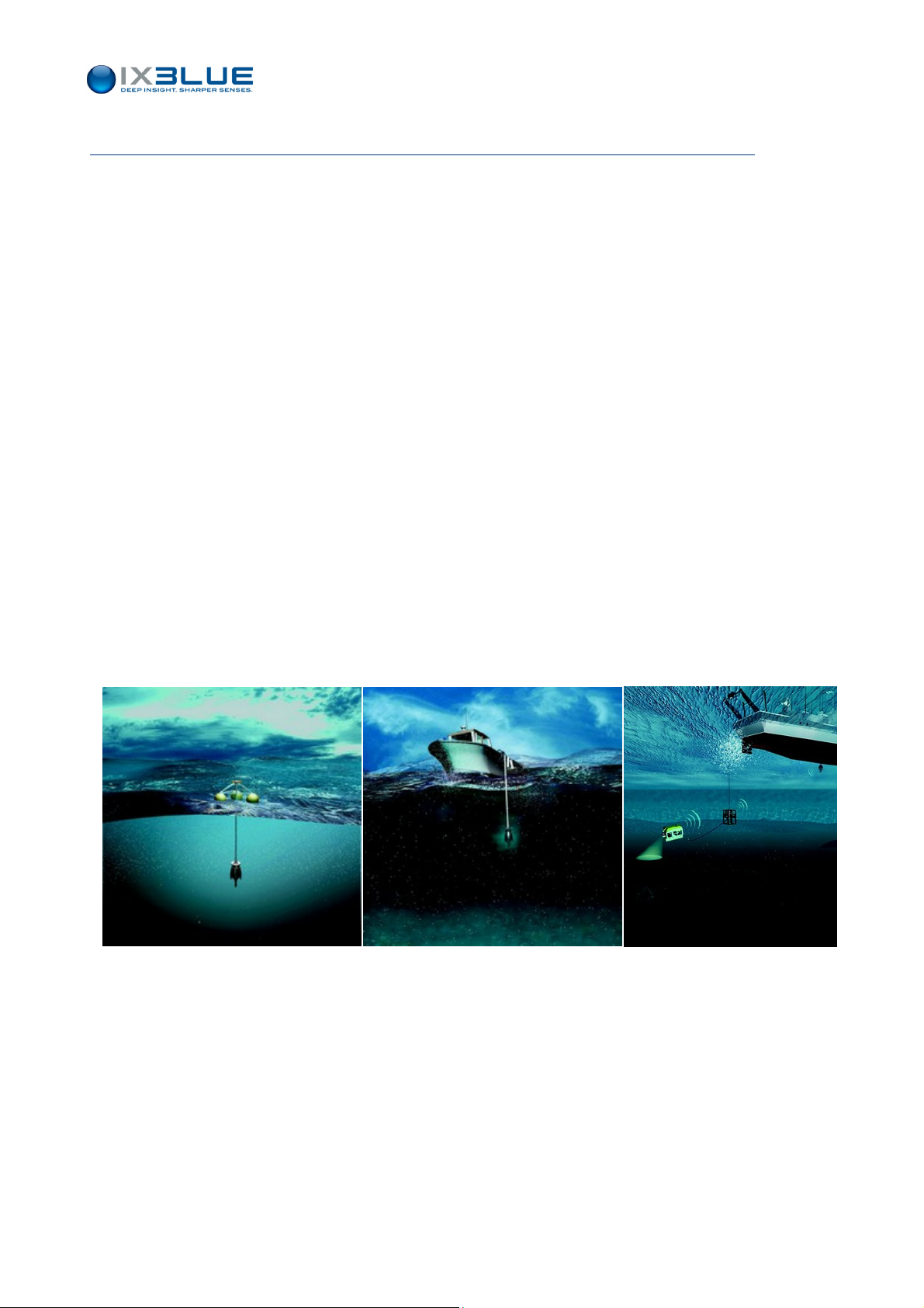
The underwater objects or vehicles are located using acoustic transponders, GAPS
acoustic array is deployed underwater and is typically mounted below the ship hull or on a
buoy (see Figure 1).
Figure 1 -
The operation principle is based on a bi-directional exchange of underwater acoustic
signals between the acoustic transponders and the GAPS unit that comprises one
transducer for transmitting and four reception hydrophones.
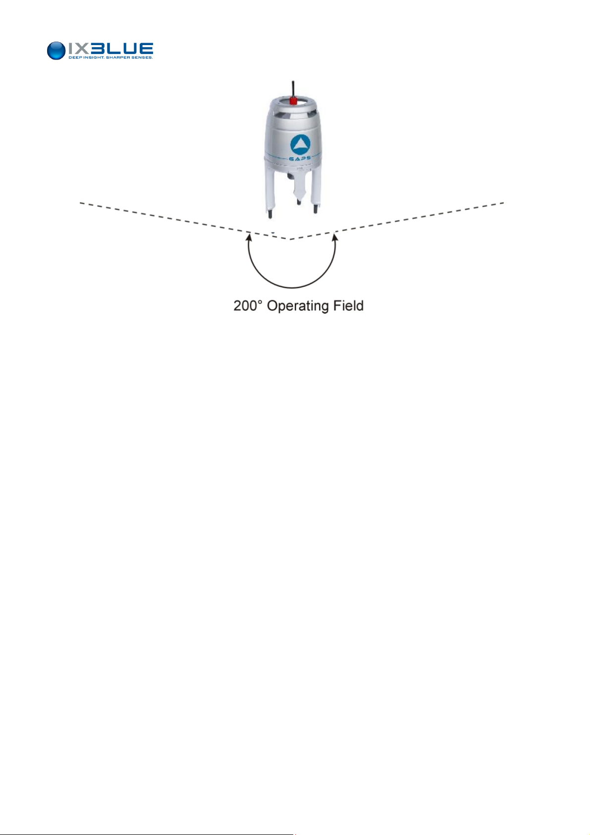
The GAPS has an operating field over 200 degrees coverage below the ship (see Figure
ring the positioning operations it can be used at 3 or 4 knots or more depending on
2). Du
the expected performances and at 12 knots during the transit operations.
GAPS typical mounting
MU-GAPS-AN-003 Ed. L – May 2012
1
Page 14
GAPS – User Guide
Figure 2 - GAPS Operating Field
MU-GAPS-AN-003 Ed. L – May 2012
2
Page 15
I.2 Acoustic Positioning Principles
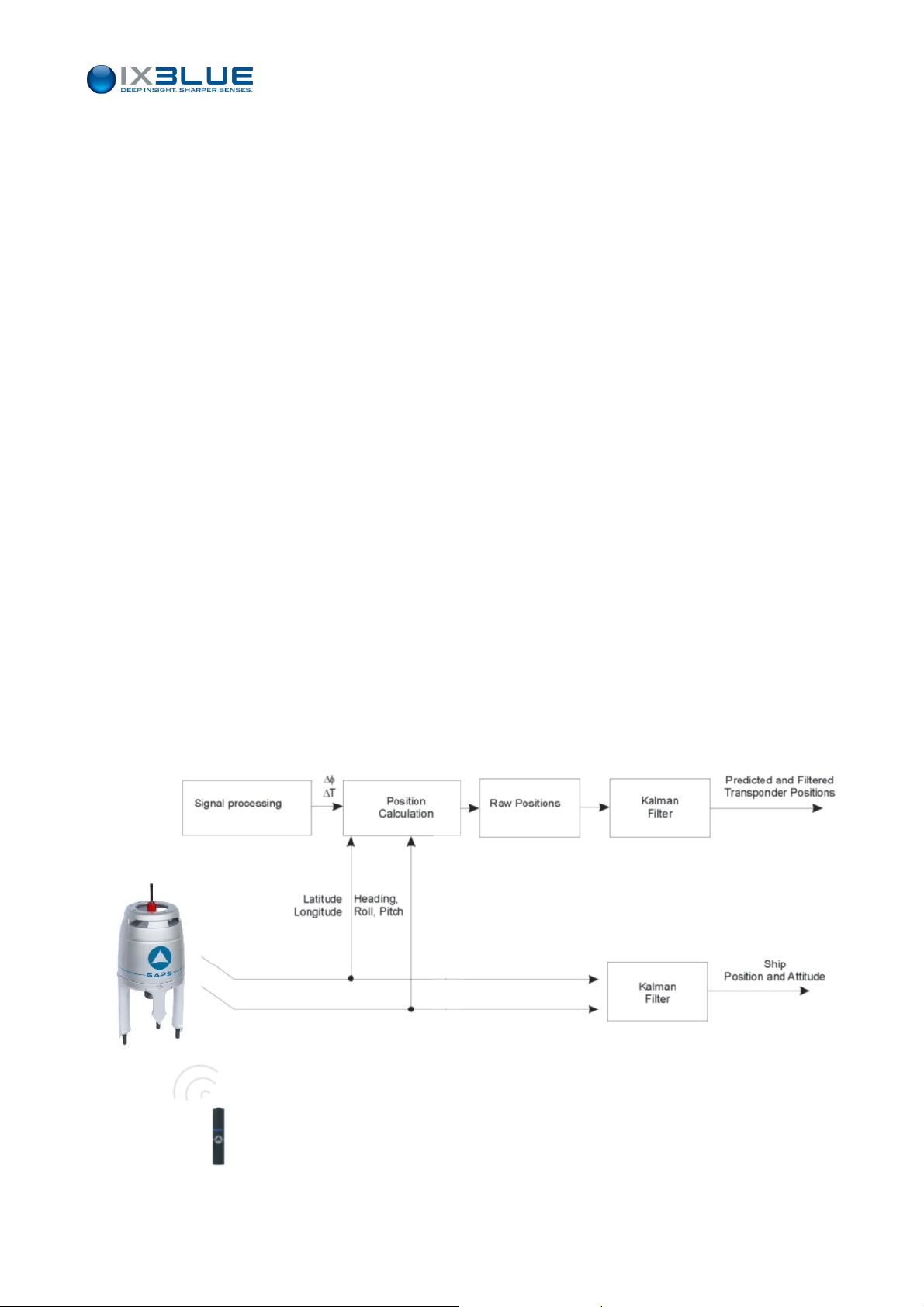
The positioning of the acoustic transponder(s) is performed as follows (see Figure 3):
• The transmitting transducer sends an interrogation signal to the transponder.
• The four receiver hydrophones of the GAPS unit receive the MFSK reply from the
transponder.
• The GAPS processing unit
detects the signal,
measures the phases of the signals arriving at the four hydrophones and the
elapsed time between the interrogation and the reply.
• GAPS takes into account the attitude of the acoustic array (provided by the internal
fiber-optic gyros at the exact moment of the reception of the signal). The processing
unit deduces the relative position of the transponder.
• The INS sensor also processes also the data coming from the DGPS antenna with its
own gyros and acceleration sensors in order to accurately determine the absolute
GAPS – User Guide
position of the acoustic array at the exact moment when the transponder signal has
been received.
• The absolute position of GAPS is given by the GPS. The position of the transponder
relative to GAPS position is computed. GAPS can then provide the accurate absolute
position of the transponder.
• This absolute position feeds a Kalman filter, which is able to provide an estimation of
the current position of the transponder in real-time.
• Additionally, the position, heading, roll and pitch of the acoustic array (or the ship) are
available as output.
Figure 3 - GAPS Operation Synoptic
MU-GAPS-AN-003 Ed. L – May 2012
3
Page 16

I.3 Technical Description
I.3.1 OVERVIEW
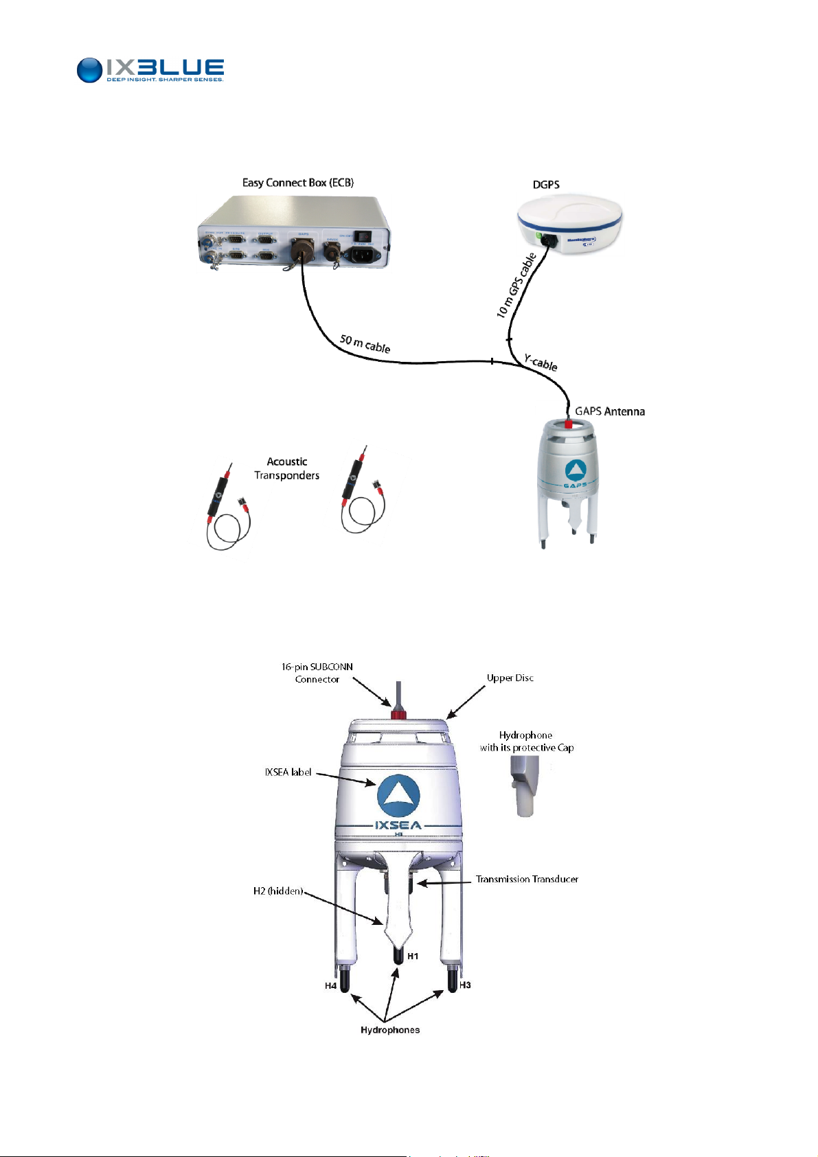
The GAPS system consists of four main parts (see Figure 4)
• The acoustic array, i.e. the GAPS unit (see section I.3.2)
GAPS – User Guide
ECB
Control
• One
• The DGPS integrated a
• Man Machin
Other ele
A junction box named Easy Connect Box (ECB) simplifying the connections between the
GAPS unit and other devices is also available (see section II.3 of this manual).
GAPS does not need any external sensor to provide the position of the transponders but
depe
used in order to
• Increase the accuracy in noisy environments
• Simplify the installation of GAPS
The Control System is any PC on which the MMI Software is installed, it can be
• Either directly connected to GAPS through the MMI DIALOG RS 422 serial link
• Or to the MMI DIALOG RS232 serial link available on the junction box
The purpose of the Control System is
or several acoustic transponders that can be mounted on objects, vehicles,
divers etc. (see section I.3.3)
ntenna (see section I.3.4)
e Interface (MMI) software used to configure (mandatory) and to
monitor (optional) the real time data (see section III of this manual)
ments of the system are listed below:
nding on the conditions, external sensors – in particular a pressure sensor - can be
• To configure GAPS (input/output configuration, sound velocity profile, etc) if necessary
• To visualize the position(s) of the transponder(s)
The use of the Control System is not mandatory once GAPS is configured: GAPS stores
all its settings when turned off and resumes its last behavior when started up.
Cables
Three cables are used in the GAPS system:
• The 50 m main cable between GAPS and the ECB. An optional length of 100 m is also
available upon request. This cable is fitted with a 16-pin SUBCONN at one end (GAPS
side) and a 19-pin SOURIAU at the other end (ECB side).
• The Y cable can be used to connect the GPS directly to the GAPS. A 6 pins
SUBCONN end is connected to the GPS. The two other ends link the GAPS to the
ECB using the 50 m main cable.
• The 10 m GPS cable links the Y cable to the GPS antenna. It is equipped with 6-pin
SUBCONN connectors.
MU-GAPS-AN-003 Ed. L – May 2012
4
Page 17
GAPS – User Guide
GPS
If the expected accuracy of an external GPS is greater than the GAPS integrated DGPS, it
is possible to connect it to the ECB (through the External GPS RS 232 serial link) and to
use its positioning data. In that case, the “Y” cable is not used.
I.3.2 GAPS U
NIT
Figure 4 – GAPS System Components
Figure 5 - GAPS Unit
MU-GAPS-AN-003 Ed. L – May 2012
5
Page 18

GAPS – User Guide
Mechanical
Description
Contents
Power Supply
GAPS Unit
GAPS has a carbon housing to deal with weight and mechanical characteristics. It is
composed of (see Figure 5)
An upper disk for handling
•
• A transmission transducer
• Four reception hydrophones of different lengths to take 3D measurements
• The four hydrophones are protected by plastic caps protect them
• A 16-pin SUBCONN connection plug
The GAPS unit contains:
• The acoustic electronics for reception based on the MSFK Chirp modulation technique
• An Inertial Navigation System (INS)
• The acoustic transmitter electronics
GAPS must be powered by a 28 to 36 V - 50W - DC power supply.
The GAPS unit ensures
• the transmission of The acoustic (or electrical) triggering signals to the Transponders,
• The reception of the replies,
• The processing taking into account the attitude provided by the fiber-optic sensor
• The transmission of the results.
I.3.3 ACOUSTIC TRANSPONDERS
Five different acoustic transponders are compatible with the GAPS system:
• MT8: the standard GAPS transponder, see a description in section I.3.3.1 and in the
specific User Guide
• ET8: equivale
dimensions, please refer to the ET8 User Guide
• BT8: directive transponder, configured only in factory (IIF, code), robust design,
batteries inside, single recurrence value at 6.7 s, no responder mode, please refer to
the BT8 User Guide
• MT9: the new generation transponder, compatible with MT8 and is configured using
control software, use additional codes and batteries, please refer to the MT9 User
Guide
• ORE 435xB: monochromatic acoustic transponder, please refer to the manufacturer
User Guide
nt to the MT8 transponder with 10 times longer autonomy with larger
MU-GAPS-AN-003 Ed. L – May 2012
6
Page 19

I.3.3.1 Acoustic Transponder MT8x2 and ET8x2 Series
The Acoustic Transponder series designed to be used with GAPS are:
• iXBlue MT 832 E – HD – R: Designed to depths up to 3,000 m (remote transducer)
• iXBlue MT 832 E – R: Designed to depths up to 3,000 m
• iXBlue MT 862 S – HD – R: Designed to depths up to 6,000 m (remote transducer)
• iXBlue MT 862 S – R: Designed to depths up to 6,000 m
• iXBlue ET 862 S – HD – R: Designed to depths up to 6,000 m (remote transducer)
• iXBlue ET 862 S – R: Designed to depths up to 6,000 m
GAPS – User Guide
Specifications
Acoustic Level
188 ± 4 dB ref. 1µPa at 1m (other levels 191 dB or 185 dB available).
Reception Channel (IIF)
The reception channel frequency, or IIF (Individual Interrogation Frequency) is selectable
with a switch (19.5, 20.0, 20.5 or 21 kHz) located on the lower end plate of the
transponder. This switch is also used to turn off the transponder or to check the batteries
(Test position). Only one reception channel is available on this series of transponder.
Transmission Channel
When the transponder is triggered by an IIF signal (or electrically triggered), it replies with
a MFSK chirp signal. This signal is composed of fourteen various pulses at frequencies
ranging from 22 to 30 kHz.
Chirp Code
The order of transmission of these frequencies is determined by the code of the chirp (22
or 23). The default code is 22.
Turn Around Time
There is a delay between the reception of the triggering signal and the transmission of the
reply. See Figure 6.
In resp
onder mode, this delay is fixed at 2 ms, when the switch position is 0 or 1 otherwise
the settings are the same as in transponder mode.
In transponder mode, this delay is adjustable from 20 to 90 ms. When the switch, located
inside the transponder (see the MT832 User Guide for further information) is in position
• 0 and 1, the delay is 20 ms
• N = 2 to 9, the delay is N x 10 ms
The default turn around time is 90 ms. See Figure 6.
Blanking Ti
me
After having transmitted, no other transmission is possible for a certain time. See Figure 6.
This pe
riod is called the blanking time and is adjustable from 0.5 to 9.9 s. The default
blanking time is 0.8 s.
The Chirp Code, Turn Around Time and Blanking Time can be selected using the switches
located inside the transponder (see the MT832 User Guide for further information).
MU-GAPS-AN-003 Ed. L – May 2012
7
Page 20
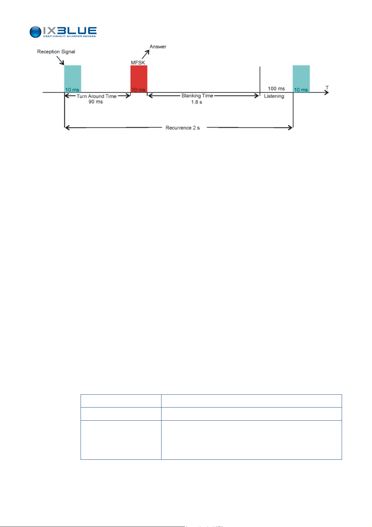
Figure 6 - Sketch of a 2 s Acoustic Transponder Recurrence
GAPS – User Guide
Optional
Features
Responder Mode
Every iXBlue acoustic transponder with the letter "-R" at the end of its designation (e.g.
MT 832 E-R) is equipped with a waterproof plug, that is used for:
• The Electrical Triggering of the transponder in Responder mode
• The External Power Supply of the transponder
Electrical Triggering
The transponder can be triggered by a 5 V differential active high signal (rising edge
trigger) 10 ms pulse sent to this input (minimum value).
On the MT 832 series, there is no need to set the transponder either to transponder or
responder mode: if an electrical triggering signal is received through the responder input,
the transponder automatically switches to responder mode and the acoustic IIF channel is
inhibited.
After 20 seconds without receiving any electrical trigger, the transponder switches back to
the Transponder mode and starts to listen to its reception channel.
Power Supply
The transponder is usually externally powered. The batteries will be used only (and
automatically) if the external supply is lost. With full batteries and transmission at 188 dB
(factory settings), approximately 50,000 chirps can be sent by the transponder. The power
can be raised to 191 dB to improve the range but in this case the maximum chirp number
decreases. The power voltage can be any value from 15 to 40 V.
Table 1 - Power Supply Specifications for MT8x2 Series
External power Range 15 - 40 VDC, 20 W peak
Consumption 900 µA under 9 VDC and 550 µA under 25 VDC
Internal back-up batteries 3 packs of 3 Lithium batteries
Type DL123A (size 2/3 A, ≅ 3.9 Ah) from DURACELL
Type CR123A from VARTA
MU-GAPS-AN-003 Ed. L – May 2012
8
Page 21
GAPS – User Guide
Table 2 - Power Supply Specifications for ET8x2 Series
External power Range 15 - 40 VDC, 20 W peak
Consumption 900 µA under 9 VDC and 550 µA under 25 VDC
Internal back-up batteries
3 packs of 6 Alkaline batteries type R20 (size D) ≅ 45 Ah
On option Lithium (LSH20 from SAFT)
In standby mode, the backup battery packs offer 4 months for MT8x2 series and 30
months for ET8x2 series (with Alkaline batteries, 50 months with Lithium batteries).
In operation, the backup battery packs offer the following typical number of pulses
transmitted depending on Sound Power Level (SPL) and temperature (which applies
from hardware version 4.7) and two types of battery pack, see Table 3 and Table 4.
e 3 – Number of Chirps vs. Battery Types for MT8x2 Series
Tabl
SPL in dB ref 1µPa at 1m
185 dB 188 dB (default configuration) 191 dB
(5 sec. transmit rate)
Temperature (Celsius) 20°C 0°C 20°C 20°C
DL123A (DURACELL) 115,000 33,000
CR123A (VARTA) 40,000
47,000
53,000
21,000
Table 4 – Number of Chirps vs. Battery Types for ET8x2 Series
SPL in dB re. 1µPa at 1m
185 dB 188 dB (default configuration) 191 dB
(5 sec. transmit rate)
Temperature (Celsius) 20°C 0°C 20°C 20°C
Alkaline (Default configuration)
Lithium (LSH20)
1 300,000 350,000
2 300,000 700,000
550,000
900,000
250,000
410,000
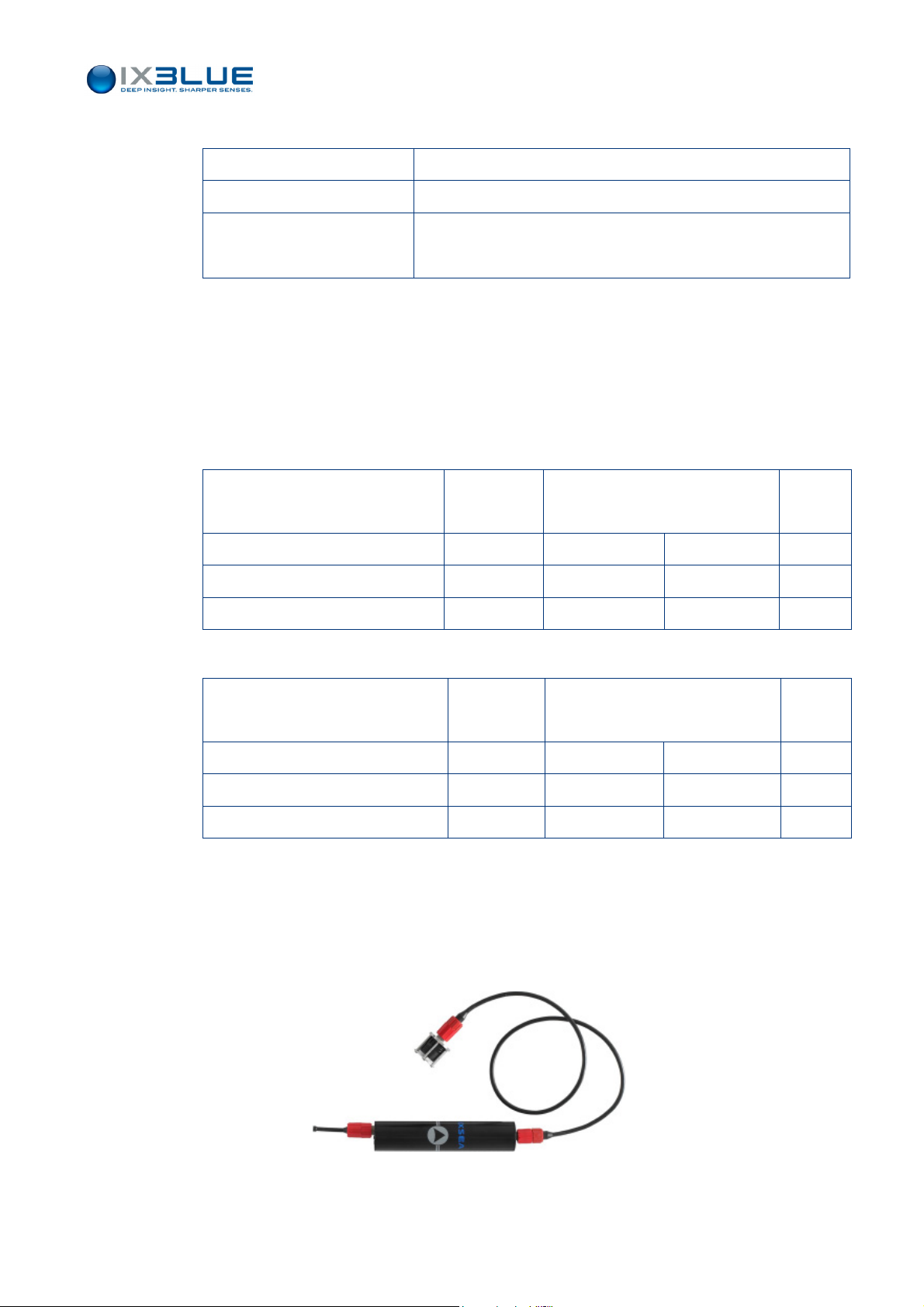
Remote Transducer
Every iXBlue Acoustic Transponder with the letters "-HD" at the end of its designation
(e.g. MT 832 E-R-HD, see Figure 7) has a transducer separate from its body with this
arated transducer the transponder can be more easily installed on a underwater
sep
vehicle. It is also easier not to mask the acoustic transmission/reception head.
Figure 7 - Acoustic transponder MT 832 E–R-HD
MU-GAPS-AN-003 Ed. L – May 2012
9
Page 22
I.3.3.2 Acoustic Transponder BT812 Series
GAPS – User Guide
BT812 Special
Features
The technical features of the BT812 beacon are set in the factory and they are only
modifiable in the factory.
• The interrogation frequency is fixed to F2 (20 kHz)
• The Chirp Code can be 22 or 23
• Turn Around Time is 25 ms
• The Blanking Time is 260 ms
• The iXBlue BT 812 S is designed for a depth up to 700 m
The BT812 beacon can neither have a remote hydrophone nor operate in responder
mode. For more details, please refer to the BT812 User Guide.
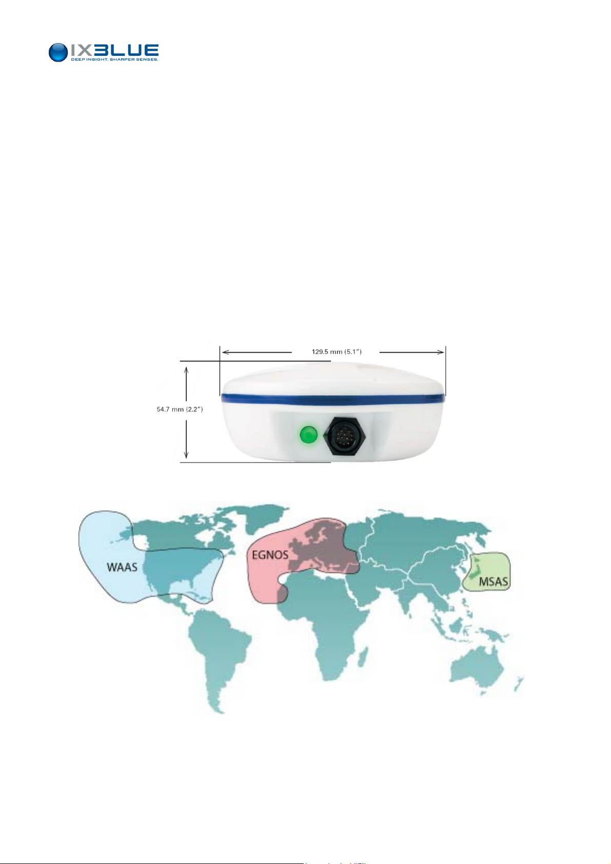
I.3.4 INTEGRATED DGPS
The integrated DGPS has a WAAS / EGNOS / MSAS compatible active antenna. See the
coverage of the three Satellite Based Augmentation Systems on Figure 9.
Figure 8 - Int
egrated DGPS
Figure 9 – WAAS, EGNOS and MSAS coverage
MU-GAPS-AN-003 Ed. L – May 2012
10
Page 23
I.4 Conventions and Specifications
I.4.1 GENERAL CHARACTERISTICS
Positioning
Characteristics Values
Range depending on ambient noise and velocity 4,000 m
Coverage 200° below the acoustic array
Acoustic Level 192 +/-3 dB ref. 1 µPa/V
Operating frequency 22 to 30 kHz MFSK chirp modulation technique
Heading / Roll / Pitch accuracy needed 0.01°
Operating / Environment
GAPS – User Guide
Characteristic Value
Power supply / consumption 28 to 36 V DC / 35 W (45 W at starting up)
Operating temperature -5 °C to 35 °C
Storage temperature -20 °C to + 70 °C
I.4.2 GEOMETRICAL CONVENTIONS
Vessel
Attitude
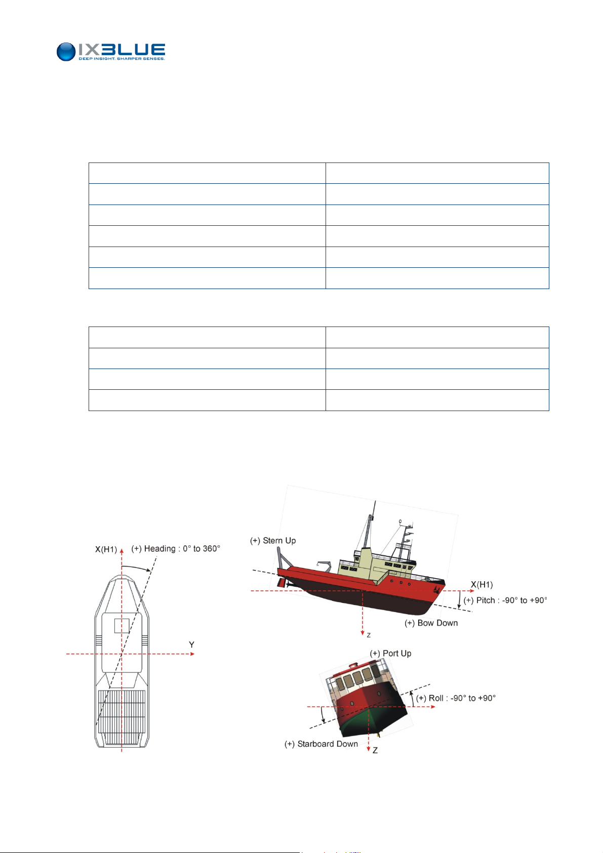
The Figure 10 shows how the Roll, Pitch and Heading are measured on the ship and the
signs of these angles.
Figure 10 – Vessel Attitude Definition and Signs
MU-GAPS-AN-003 Ed. L – May 2012
11
Page 24
GAPS – User Guide
Hydrophones
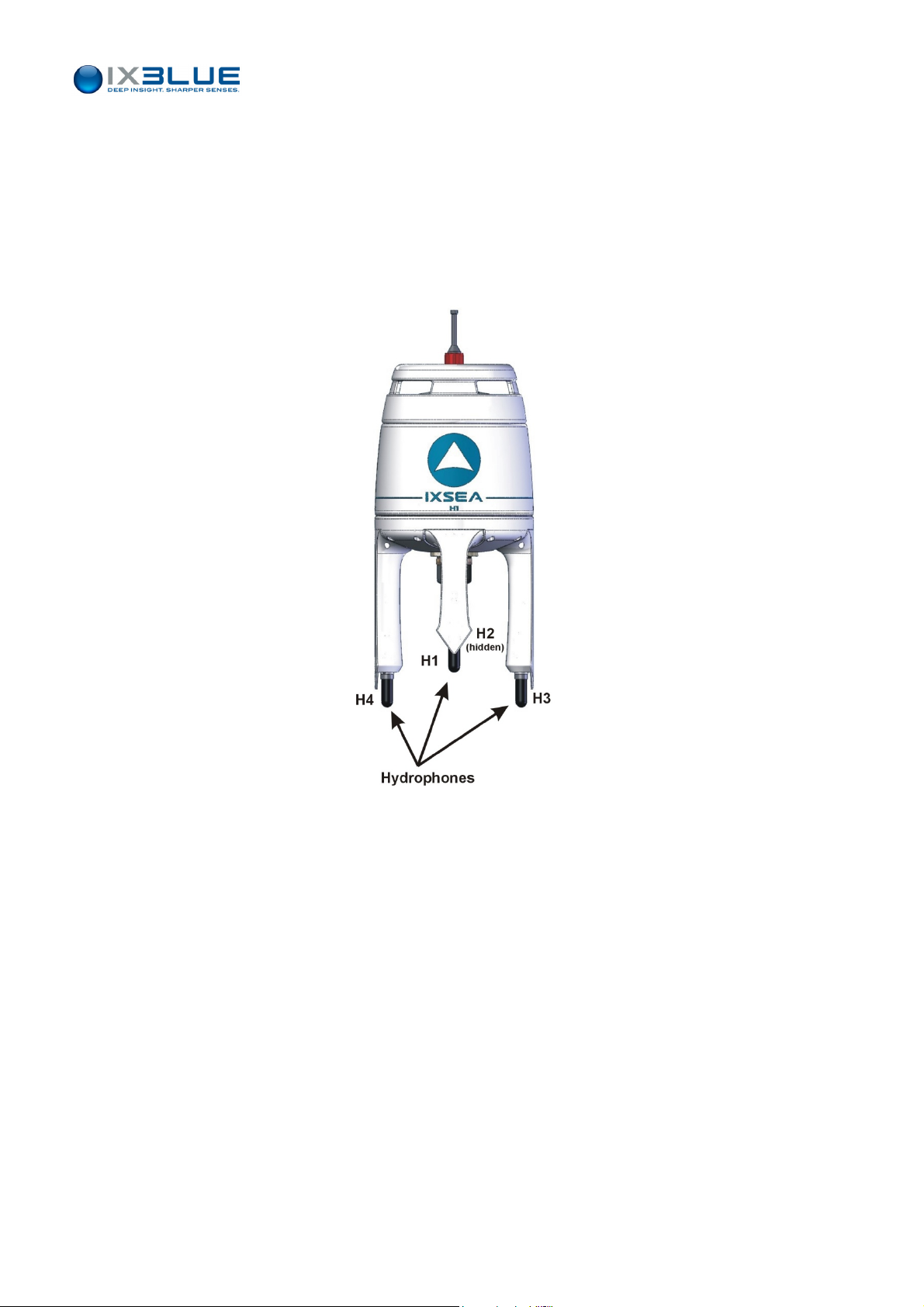
The GAPS reference frame is based on the H1, H2, H3 and H4 hydrophones.
The hydrophones are numbered as follows (see Figure 11):
•
H1 is a short arm hydrophone, it is written H1 on it
• H2 is the short arm hydrophone located to the opposite of H1 short arm hydrophone
• H3 is the long arm hydrophone located on the right when H1 hydrophone faces you
• H4 is long arm hydrophone located to the opposite of H3 long arm hydrophone.
Reference
Axes
Figure 11 - H1, H2, H3 and, H4 hydrophones
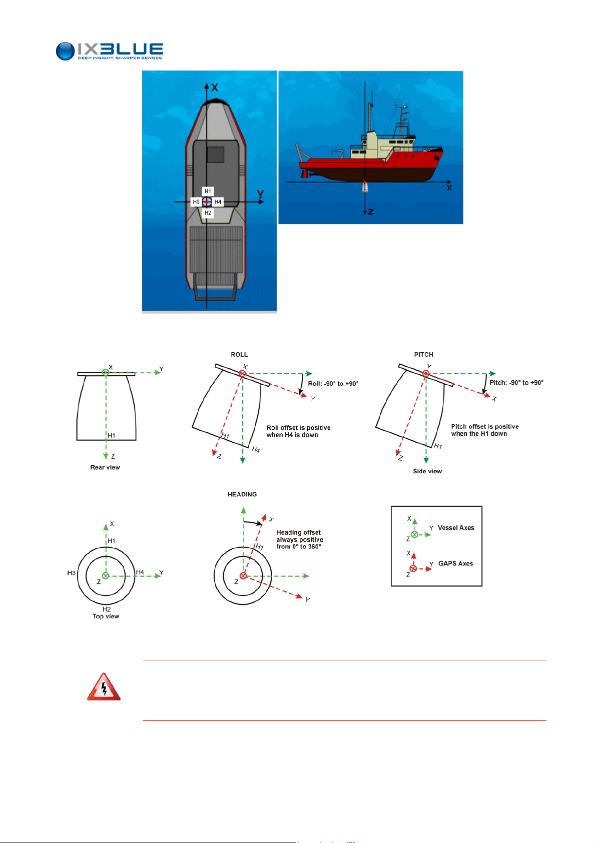
The axes in the GAPS reference frame are as follows (see Figure 12 and Figure 13):
GAPS being in vertic
al position,
• H1 & H2: longitudinal axis (X) – H1 in front (positive)
• H3 & H4: transverse axis (Y) – H4 on starboard (positive)
• Z-axis positive towards the sea bottom
MU-GAPS-AN-003 Ed. L – May 2012
12
Page 25
GAPS – User Guide
Figure 12 - GAPS reference axes
Figure 13 - GAPS angular offsets
T
O INSURE COMPATIBILITY WITH OUR EXISTING SYSTEMS AND SOFTWARE, THE CONVENTION USED
FOR THE X AND Y AXES (SEE FIGURE 12 AND FIGURE
CONVENTION USUALLY USED
(X
TO THE BOW, Y TO PORT, Z UPWARD
MU-GAPS-AN-003 Ed. L – May 2012
13)
MAY BE DIFFERENT FROM THE
).
13
Page 26
GAPS – User Guide
I.4.3 M
ECHANICAL SPECIFICATIONS
Characteristics Values
Housing Carbon
Weight in air / water 16 kg / -7 kg
Housing diameter x H (mm) 296 x 638 (fits in 12” gate valves)
Array depth-rating 25 m
Table 6 - Acoustic Array Cable 50 m (± 1.5m)
Connector SUBCONN on
GAPS side
Connector Souriau on ECB
side
Cable Diameter 15 mm
Table 5 - Acoustic Antenna
16 pins
diameter connector 26 mm
diameter locking sleeve 35.5 mm
diameter 26 mm
19 pins
Dynamic Bend Radius 150 mm
Static Bend Radius 75 mm
Breaking Strain 150 DaN
T
HE
GAPS
CABLE IS NOT A TOW CABLE
.
MU-GAPS-AN-003 Ed. L – May 2012
14
Page 27
I.4.4 ELECTRICAL SPECIFICATIONS
GAPS – User Guide
Connection
You can find below a table describing the connections of all the 19-pins SOURIAU
connector (see Figure 14) connecting the main cable to the ECB (see Table 7).
OM OA OB
OL ON OP OC
OK OU OV OR OD
OT OS OE
OJ
OH OG OF
Figure 14 - 19 PINS Souriau socket (Ref. 851 06EC1419S50)
Table 7 - Association of the SOURIAU 19-pin, SUBCONN 16-pin and signals
MINI SUBCONN SOURIAU 851 Signal
1
2
3
4
5
6
7
8
9
10
11
12
13
14
15
16
M
B
C
P
N
L
D
R
A
E
S
T
J
F
U
K
V
G
H
PWR +
PWR GND
SYNCHRO IN +
SYNCHRO IN -
SYNCHRO OUT - RESPONDER MODE +
SYNCHRO OUT - RESPONDER MODE -
OPTIONAL EXTERNAL PRESSURE SENSOR IN RS 422 –Rx+
OPTIONAL EXTERNAL PRESSURE SENSOR IN RS 422 –Rx-
PRESSURE SENSOR WIRES SHIELD
MMI DIALOG INPUT – RS 422 –Rx+
MMI DIALOG INPUT – RS 422 –Rx-
MMI DIALOG OUTPUT – RS 422 –Tx+
MMI DIALOG OUTPUT – RS 422 –Tx-
MMI WIRES SHIELD
OPTIONAL EXTERNAL GPS MESSAGE INPUT – RS 422 –Rx+
OPTIONAL EXTERNAL GPS MESSAGE INPUT – RS 422 –Rx-
GPS WIRES SHIELD
STANDARD OUTPUT – RS 422 –Tx+
STANDARD OUTPUT – RS 422 –Tx-
MU-GAPS-AN-003 Ed. L – May 2012
15
Page 28
GAPS – User Guide
External
Power Supply
End User
System
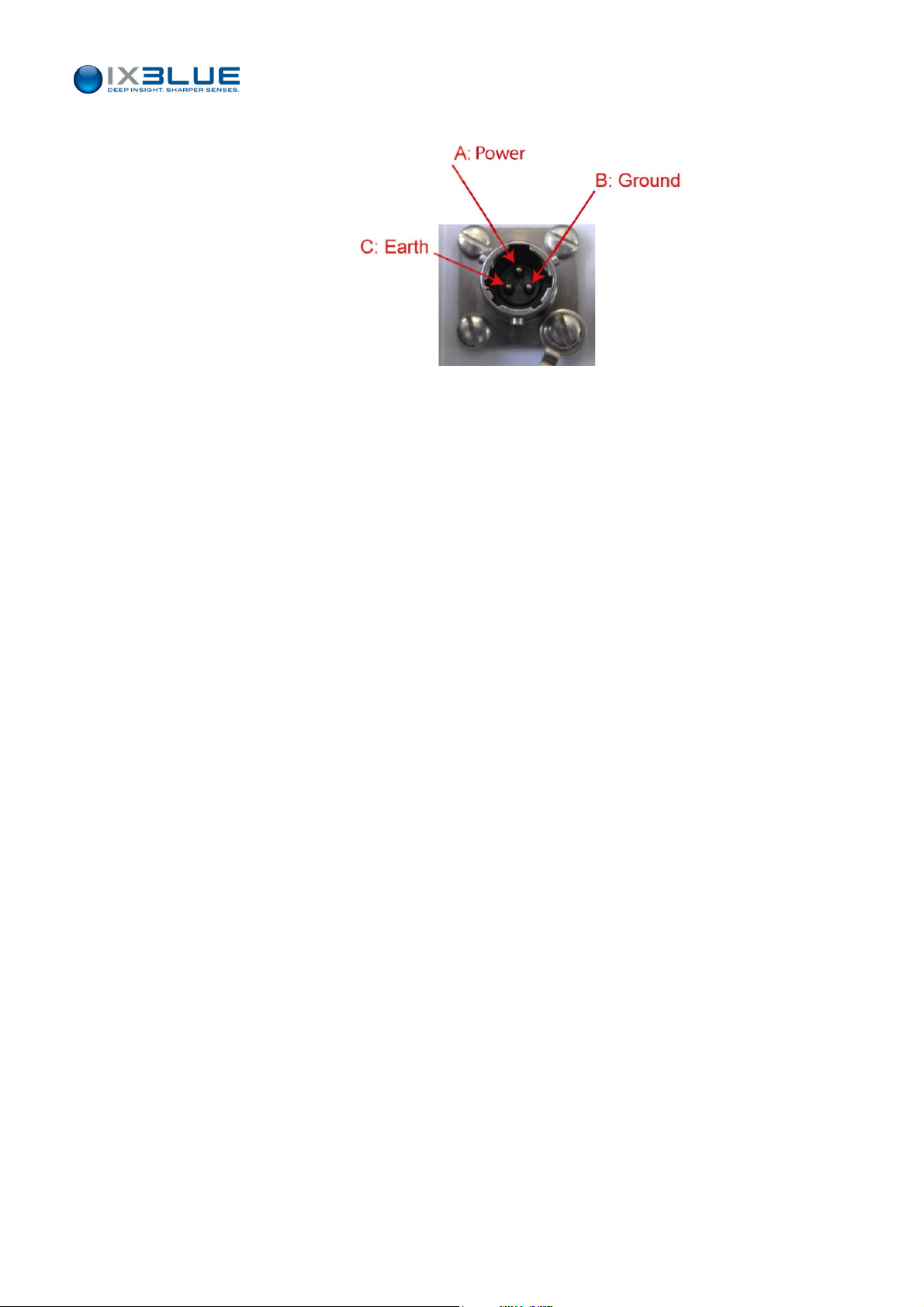
GAPS must be electrically powered by a 28 to 36 V / 50W DC source. See Figure 15.
Figure 15 – 28 to 36 V power supply 3-pin SOURIAU plug
The whole system (GAPS+ECB+PC) must be powered by a 110-220 V / 50Hz source
(consumption: less than 50 W).
The positioning messages are available on the Standard Output RS 422 serial link (cable
output) or on the RS232 serial link (ECB output). These four DB9/RS232 ECB input/output
(Pressure IN, MMI IN and OUT, GPS IN, Output OUT) are used with straight cables.
Baud rate, parity and, bit stop are adjustable in the MMI Software (see Part IV of this
manual).
Control
System
A RS422 or a RS232 (ECB) serial link is necessary to connect the MMI DIALOG link
(baud rate 57,600, parity odd and stop bit 2 are fixed).
MU-GAPS-AN-003 Ed. L – May 2012
16
Page 29
GAPS – User Guide
Responder
Mode
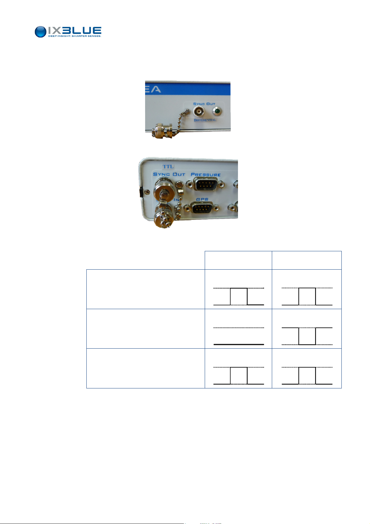
The SYNCHRO OUT – Responder mode signal is sent to the transponder if the responder
mode is activated. Two types of signal are available:
• A differential triggering signal is sent from the BNC of the front face of the ECB.
• A TTL triggering signal is sent from the BNC of the rear face of the ECB.
Table 8 – TTL and differential synchro out signals
Synchro OUT +
TTL Differential
0 / 5 V
Synchro OUT –
0 V
(Synchro OUT +) - (Synchro OUT –)
0 / 5 V
A TTL signal can independently trigger a TTL and differential input.
A differential signal cannot trigger a TTL input.
0 / 3.5 V
0 / -3.5 V
0 / 7 V
The simultaneous output of two different signals allows the independent triggering of both
MT8 and MT9 transponders (from all possible configurations).
Most of the time, these signals have to be re-amplified between GAPS and the
transponder. There can be a delay between the transmission of this signal by GAPS and
its reception by the transponder.
MU-GAPS-AN-003 Ed. L – May 2012
17
Page 30
GAPS – User Guide
The Table 9 below describes the compatibility between the different types and versions of
iXBlue transponders with the different versions of the ECB.
Table 9 – Compatibility between ECB and transponders
External
Synchro
ECB before 09/ 2010
ECB between 09/ 2010 and 01/ 2012
ECB after 01/ 2012
MT8
OK OK OK
OK NOK OK
OK
MT9 before 02/2012 MT9 after 02/ 2012
OK rear of ECB
OK
NOK front of ECB
I
F YOU ARE IN ONE OF THE SITUATIONS OF INCOMPATIBILITY DESCRIBED IN THE TABLE 9, CONTACT
IXBLUE TECHNICAL SUPPORT
.
The SYNCHRO IN (external) triggering signal is an active high pulse longer than 100 µs
(0 - 5 V). The GAPS is triggered on the rising edge.
The duration between two consecutive SYNC IN pulses must be greater than 1 s.
Electrical level Active High Length
External GPS
0 - 5 V
≥ 100 µs
If GAPS is triggered from the outside and in responder mode, with a transponder in
responder mode triggered on the sync IN input (the triggering pulse length must be higher
than 5 ms), the synchro shift between the recurrence and the transponder will last 1 s
maximum. For this reason, it is strongly recommended to trigger the transponder on the
Sync OUT.
If used, an external GPS has to be connected to the external optional GPS message input
RS 422 serial link or RS232 when using the ECB.
Baud rate (maximum 57,600 bauds), parity and bit stop are adjustable from the MMI
Software.
The message expected by GAPS is the standard NMEA $xxGGA message (see section
VI.1.1) and xxZDA (see section VI.1.2) is automatically taken into account for the update
of the GAPS i
nternal time if available. “xx” means that the first two letters of the format
name can be any letter.
MU-GAPS-AN-003 Ed. L – May 2012
18
Page 31
GAPS – User Guide
II I
NSTALLING
Before installing GAPS for the first time, it is recommended to check the contents of the
boxes delivered (see section II.1). The installation is achieved in four steps:
Installing the GAPS antenna, see section II.2
•
•
Installing the Easy Connect Box, see section II.3
•
Installing the DGPS Antenna, see section II.5
•
Installing a Transponder, see section II.6
GAPS
II.1 Checking of the Pack Contents
You have just received your equipment in protective boxes. Before starting the installation,
we recommend that you check the contents of the pack and the equipment
immediately on receipt of your GAPS System. Check that all items are present on
delivery and that none has been damaged during shipping.
Use the packing-list detailing all the shipped items. This packing list was compiled by
iXBlue shortly before shipment.
O
N RECEIPT OF THE EQUIPMENT, ITS OVERALL CONDITION SHOULD BE CHECKED AND IXBLUE
INFORMED OF ANY DAMAGE SUFFERED DURING SHIPPING. CHECK THAT EVERY PARCEL SHOCK
. I
LABEL IS STILL WHITE
INSURANCE COMPANY
N
EVER OPEN THE
N THE OPPOSITE CASE IT IS HIGHLY RECOMMENDED TO CONTACT THE
.
GAPS
UNIT
.
MU-GAPS-AN-003 Ed. L – May 2012
19
Page 32

II.2 Installing the Acoustic Antenna
GAPS – User Guide
II.2.1 R
ECOMMENDATIONS PRIOR TO INSTALLATION
Containing its own attitude sensor, GAPS can be installed at the location and in the
position that best suit the operational constraints.
Nevertheless, some factors concerning the installation can decrease the final global
performances of the system if they are not taken into account.
II.2.1.1 Noise Level
As with every acoustic system, the noise generated by the environment can decrease the
performance of the system. Range and accuracy of the positioning greatly depend on the
signal to noise ratio.
On a ship, it is recommended to install the GAPS unit in the front third of the ship (in order
to decrease the noise level from the propeller) and as far as possible from any water
discharge system.
II.2.1.2 Reflective Surfaces
Even though the MFSK signal treatment strongly increases the multi-path immunity, there
are still situations where the direct signal detection is disturbed by reflective signals.
To avoid such cases, it is recommended that GAPS is kept at least 1 m away from
reflective surfaces.
The sea surface may be considered as a reflective surface depending on the depth of the
transponder: if both the transponder and the acoustic array are close to the surface, there
will be multi-path phenomenon at specific distances.
The transponder depth is usually an operational constraint and therefore difficult to
change. In that case, it is recommended to increase the depth of GAPS.
For deep-water applications (more than 250 m), a depth of 1 m is usually enough for the
acoustic array. For more details about GAPS performances versus depth, see section
IV.1.
II.2.1.3 Corrosion
An electrical equipment which operates underwater like GAPS is submitted to differences
of potential that can lead to the corrosion of the mechanical structure of the antenna.
T IS YOUR RESPONSIBILITY TO MINIMIZE THE DIFFERENCES OF POTENTIAL BETWEEN THE
I
ANTENNA AND THE SURROUNDING STRUCTURES. THE
ELECTROLYTIC PROTECTION OF THE VESSEL
GAPS
GAPS
ANTENNA MUST BENEFIT FROM THE
.
MU-GAPS-AN-003 Ed. L – May 2012
20
Page 33
GAPS – User Guide
Depending on the electrical installation of the different vessels (for example pole
connected to the ground or not), it is possible to change the ground configuration of the
GAPS in the ECB. This operation must be done by an iXBlue engineer, during the
installation of the equipment. See section II.4 for more details.
ONTACT IXBLUE TECHNICAL SUPPORT IF YOU NOTICE CORROSION DAMAGES ON THE EIGHT
C
II.2.2 I
Orientation
TITANIUM SCREWS HOLDING THE
THE PAINT FOR EXAMPLE
NSTALLATION PRINCIPLES
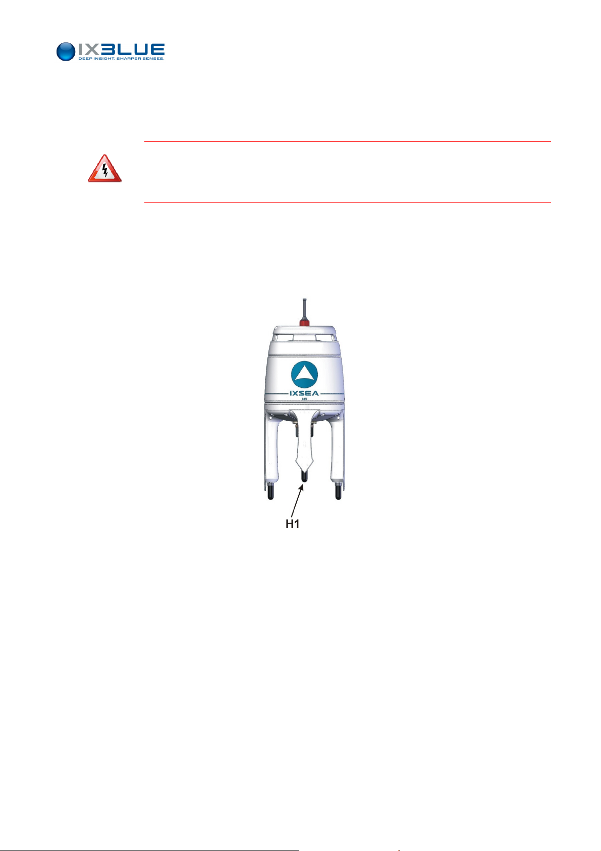
When you set up GAPS on the ship, the hydrophone H1 (see Figure 16) must be
oriented towards the bow. Positioning H1 towards the bow generates more drag but, in
this position, the acoustic noise is reduced.
GAPS
OR DIRECTLY ON THE ANTENNA HOUSING (BLISTERS OF
).
Insulation
Location
Mechanical
Plans
Figure 16 - GAPS H1 hydrophone location
In case GAPS is fixed on metallic plates of different materials (electro-chemical potential,
aluminum for example) it is necessary to electrically insulate it in order to avoid any
electro-galvanic reaction that will result in structure corrosion and GAPS acoustic array
fouling.
The location requirements for the GAPS antenna are listed below:
• There must be enough place for the wire way on the connector side of GAPS
• GAPS can be fixed using the eight M8 screws, however as there are several possible
deployments (see section II.2 for how to install your GAPS unit).
The me
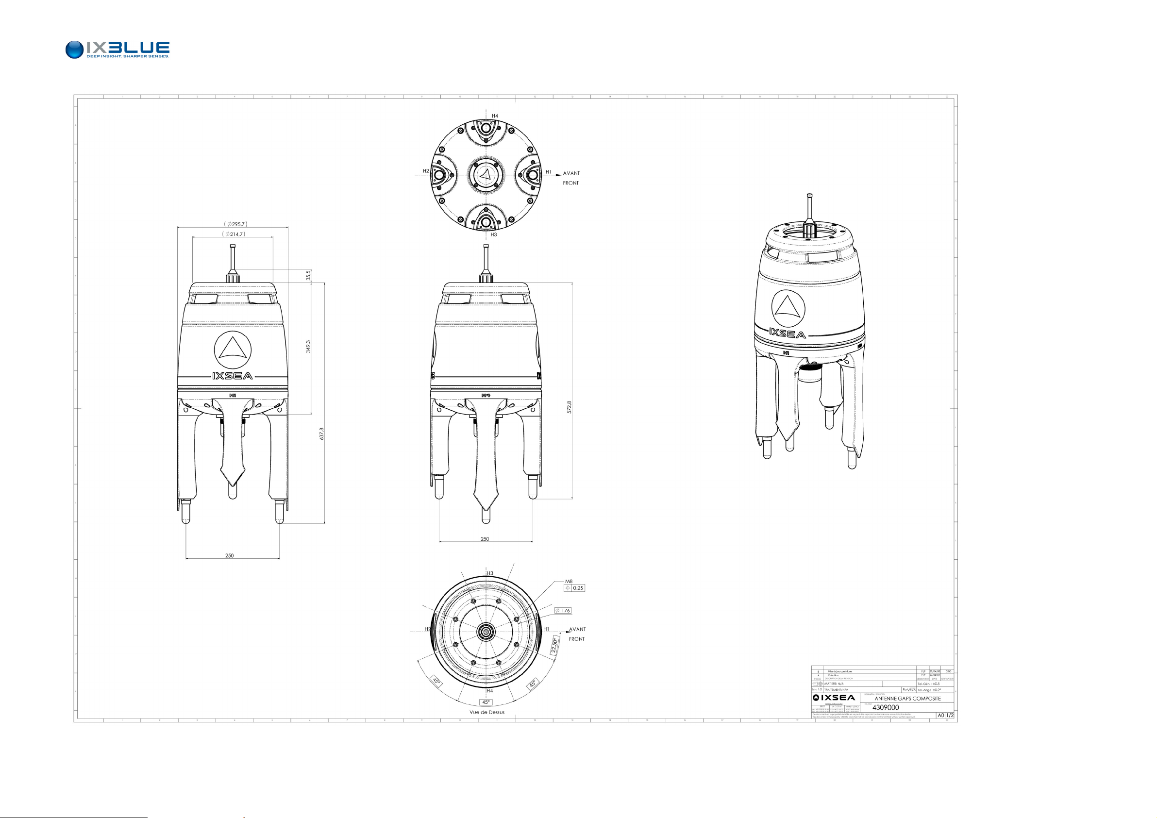
chanical plan of the antenna is displayed on Figure 17.
MU-GAPS-AN-003 Ed. L – May 2012
21
Page 34

GAPS – User Guide
PAGE INTENTIONALLY LEFT BLANK
MU-GAPS-AN-003 Ed. L – May 2012
22
Page 35
GAPS – User Guide
Figure 17 – GAPS Mechanical Plan
23
MU-GAPS-AN-003 Ed. L – May 2012
Page 36

GAPS – User Guide
PAGE INTENTIONALLY LEFT BLANK
24
MU-GAPS-AN-003 Ed. L – May 2012
Page 37
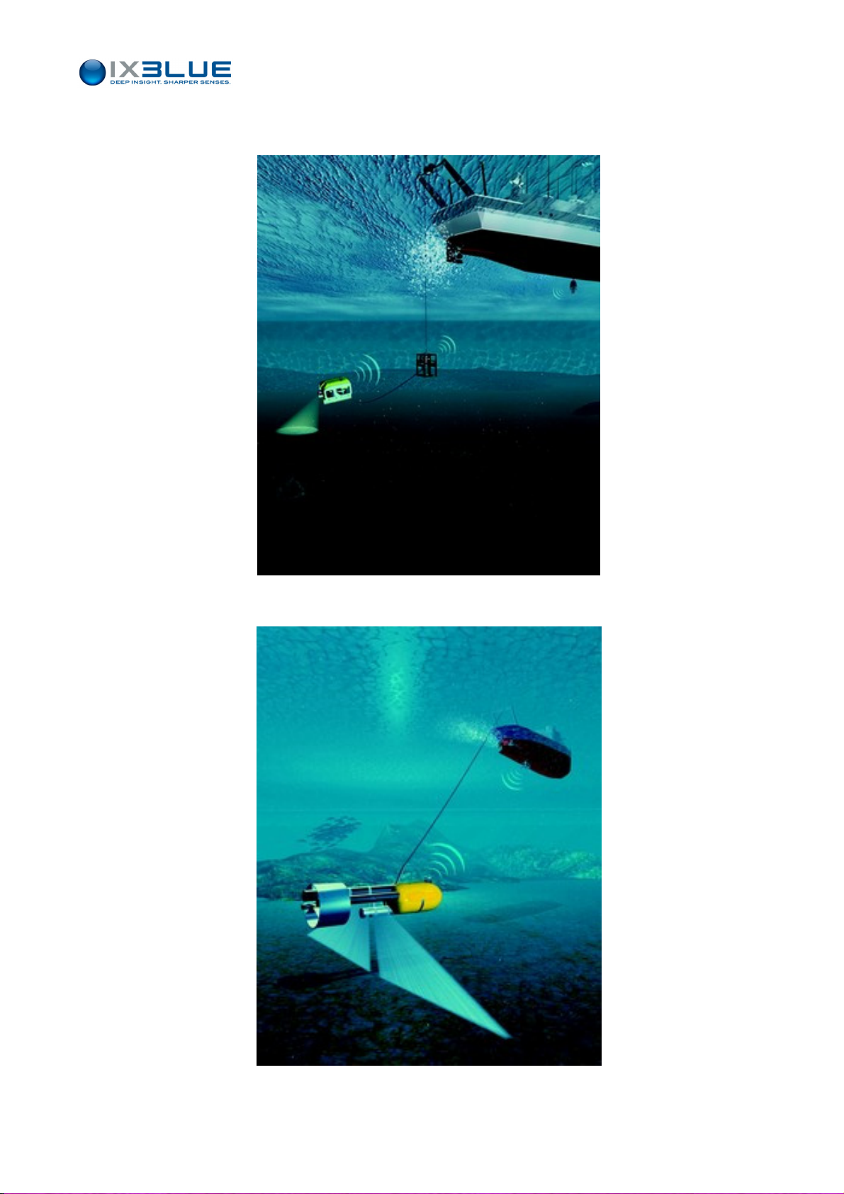
II.2.3 DEPLOYMENT EXAMPLES
GAPS – User Guide
Figure 18- GAPS fixed on the hull and a transponder on a ROV
Figure 19 GAPS fixed on the hull and a transponder on a tow fish
MU-GAPS-AN-003 Ed. L – May 2012
25
Page 38
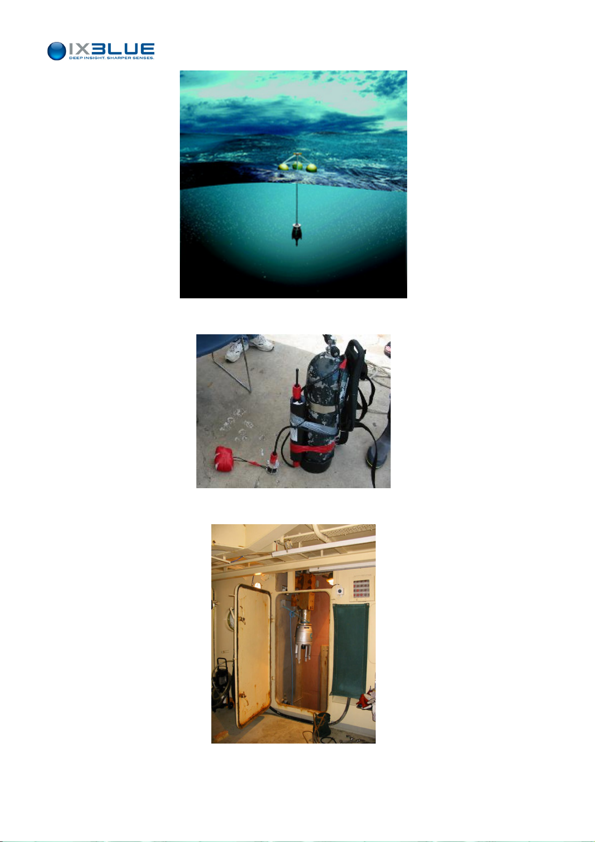
Figure 20 - GAPS mounted under a tripod
GAPS – User Guide
Figure 21 - Transponder fixed on a scuba cylinder
Figure 22 – GAPS inside a hoisting pool
MU-GAPS-AN-003 Ed. L – May 2012
26
Page 39
GAPS – User Guide
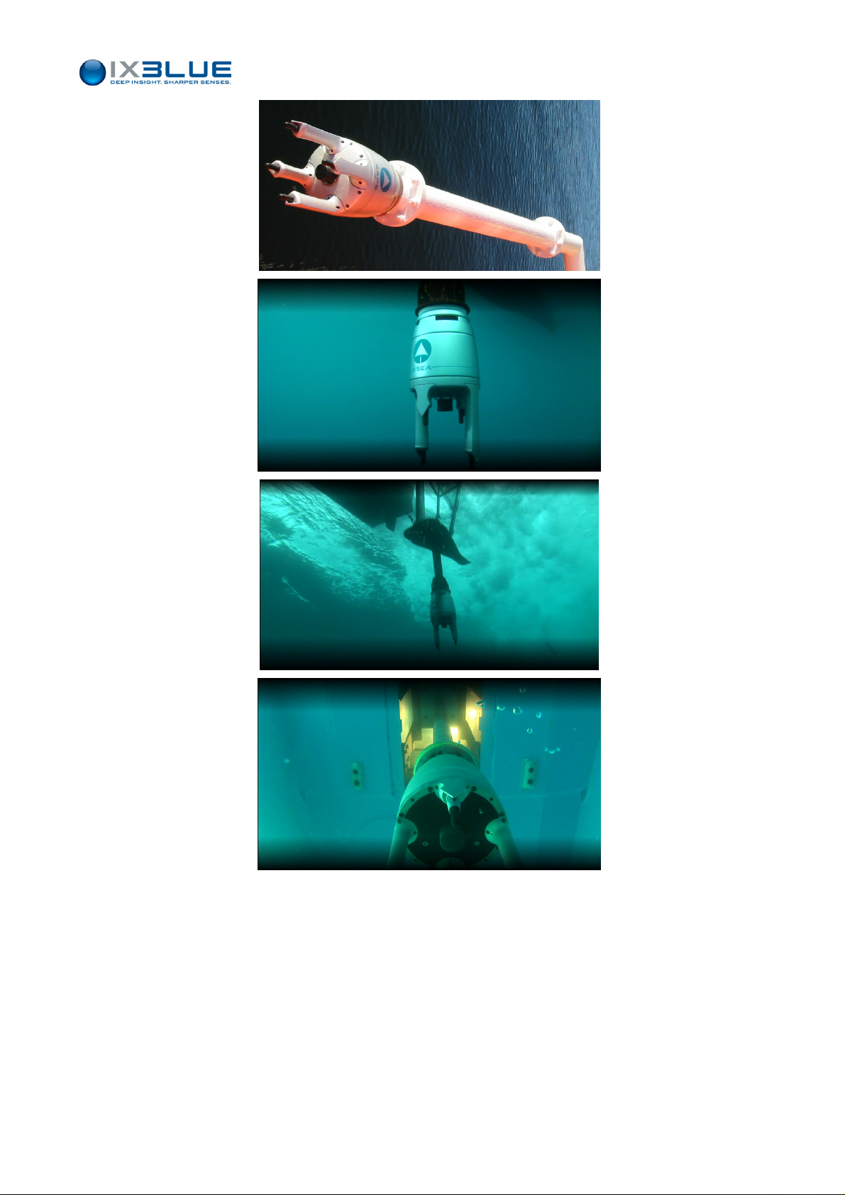
Figure 23 - Different installations on a pole, underneath the keel or in a moon pool
MU-GAPS-AN-003 Ed. L – May 2012
27
Page 40
II.3 Installing the Easy Connect Box
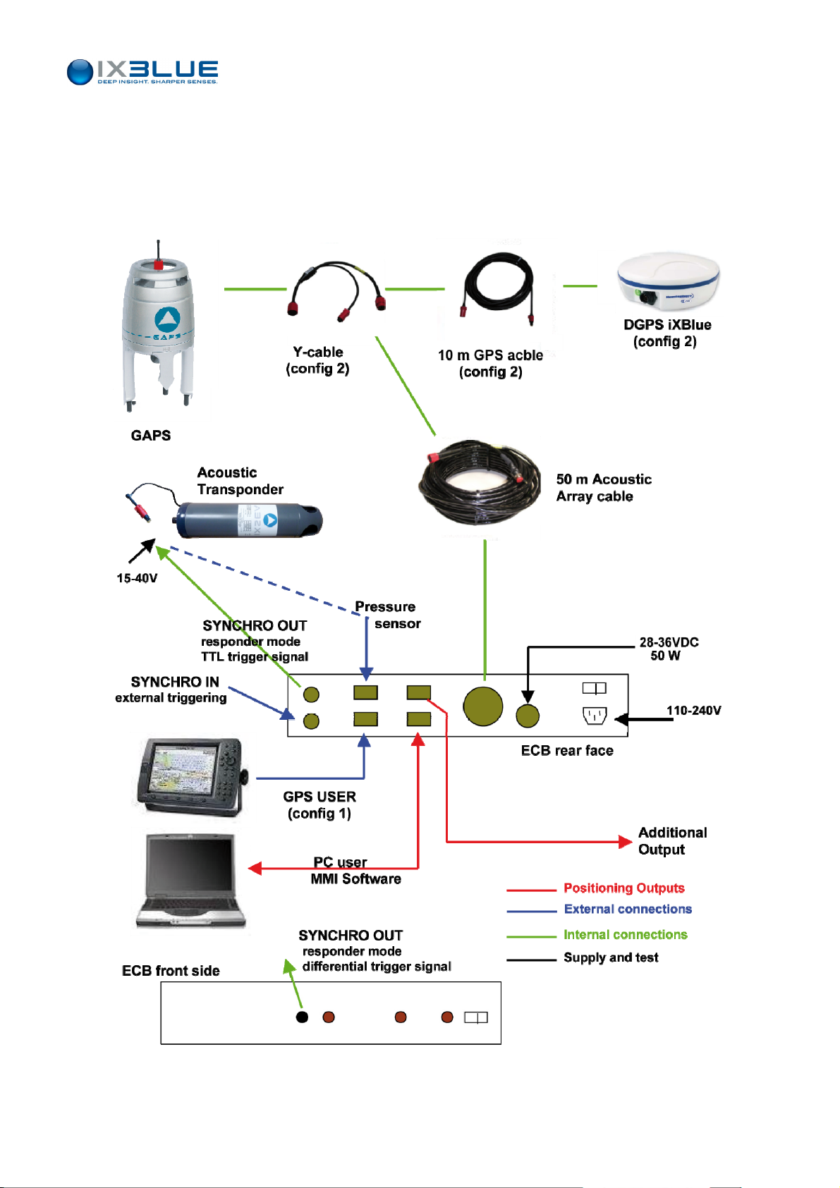
The connections between the different devices can be set up through the iXBlue junction
box called ‘Easy Connect Box’ (ECB). See Figure 24. Through the Easy Connect Box, you
set up all connections between the different devices of the system.
can
GAPS – User Guide
Figure 24- GAPS System Architecture
MU-GAPS-AN-003 Ed. L – May 2012
28
Page 41
GAPS – User Guide
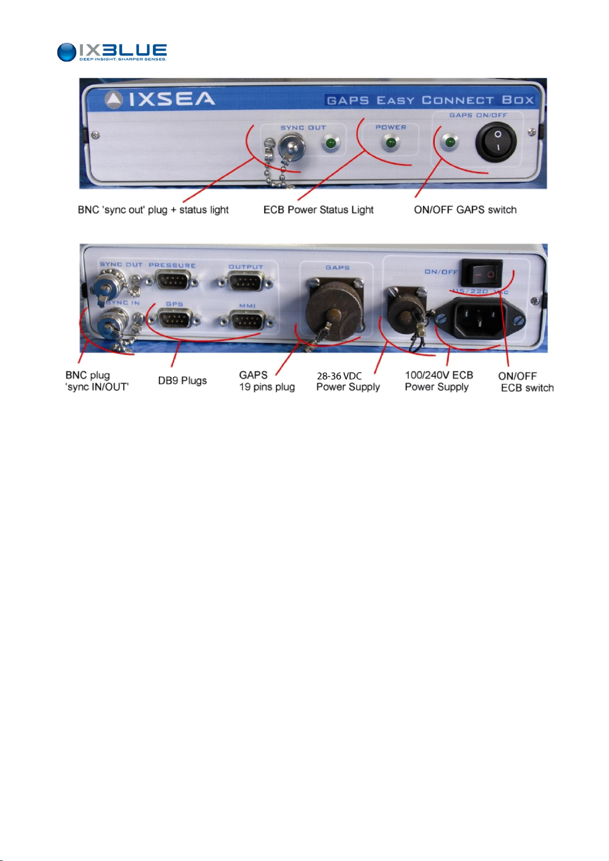
Figure 25 - ECB Box, Front Face and Back Face
II.3.1 CONNECTIONS ON THE FRONT FACE
From left to right (see Figure 25):
• BNC SYNC OUT plug with its status light triggers the transponder in responder mode
with a differential signal
• Power status light for ECB (ON/OFF switch on the back)
• ON/OFF switch for GAPS with its status light
II.3.2 CONNECTIONS ON THE BACK FACE
From left to right (see Figure 25):
• 2 BNC plugs for
SYNC OUT to trigger the transponder in responder mode with a TTL signal
SYNC IN GAPS acoustic recurrence triggered by an external device (side-scan
sonar for example)
• 4 DB9 plugs for RS232 Serial Links (use of straight cables)
Input connection to the PRESSURE sensor, the input configuration of which
being Baud rate = 19200 bps, Data Bits = 8, Parity = none, Stop Bit =1
Note: 10 dBar correspond to 0 m and 20 dBar correspond to 10 m depth.
OUTPUT of position and attitude available in various formats
Input/output MMI connection to the user PC for configuration and real-time
control
MU-GAPS-AN-003 Ed. L – May 2012
29
Page 42
GAPS – User Guide
Input GPS connection to an external GPS receiver
• The GAPS 19-pin plug for the Acoustic Array cable
• The 28 to 36 V - 50W DC (2A) ECB power supply plug
• The 100 to 240 V, 50-60Hz ECB power supply plug, automatically detected, no
adaptation needed
• The ON/OFF switch for ECB
Both 100 – 240 V and 28 – 36 VDC ECB power supply inputs can be connected
simultaneously. The 100 – 240 V is converted into 28 VDC. The ECB automatically
switches on the highest voltage input between the 100 – 240 V converted and the 28 – 36
V.
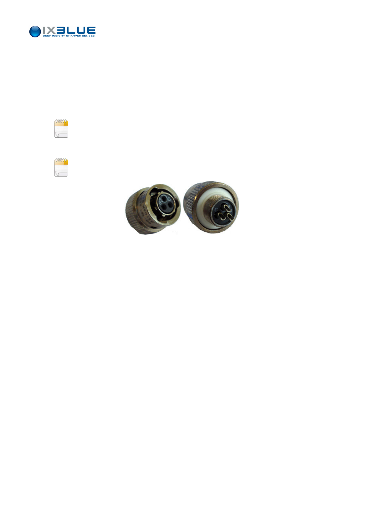
The ECB is supplied with a female connector on which can be welded a 28 – 36 VDC
power supply cable of your own. See the connector in Figure 26.
Figure 26 – Female Connector for ECB 28 – 36 VDC Power Supply
MU-GAPS-AN-003 Ed. L – May 2012
30
Page 43
II.4 Checking the Electrical Ground Continuity
You must ensure that the electrical installation is correct in order to prevent the antenna
from corrosion. Before proceeding to the test, please make sure that you have:
• Installed the GAPS acoustic antenna
• Installed and powered the ECB
• Connected the cable between the ECB and the acoustic antenna
The test consists in measuring the voltage between the GAPS antenna and the hull of the
ship with a multitester.
Procedure
Step Action
1.
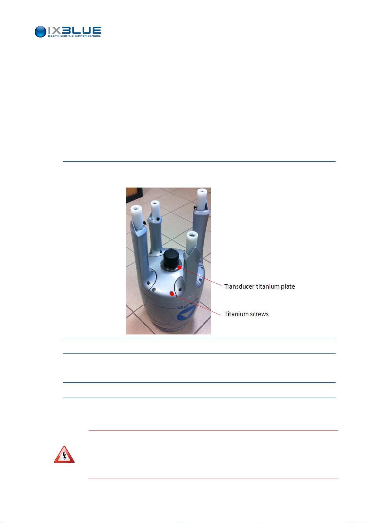
Put the first probe of the multitester on a conductive part of the housing of the GAPS
antenna. It can be the transducer titanium plate or the titanium screws.
GAPS – User Guide
2.
Put the second probe on a conductive part of the ship hull.
3.
Read the voltage between these two points.
The voltage must be below 1.0 V.
4.
End of procedure.
If the voltage between the GAPS antenna and the hull of the ship is below 1.0 V, the
system is electrically well installed.
F THE VOLTAGE BETWEEN THE
I
1.0 V,
CORROSION WILL IMPACT YOUR SYSTEM. A MODIFICATION MUST BE MADE IN THE
CHANGE THE ELECTRICAL GROUND CONFIGURATION
C
ONTACT IXBLUE TECHNICAL SUPPORT. SEE COORDINATES PAGE
GAPS
ANTENNA AND THE HULL OF THE SHIP IS GREATER THAN
. T
O DO SO
MU-GAPS-AN-003 Ed. L – May 2012
:
133.
ECB
TO
31
Page 44
II.5 Installing the GPS Antenna
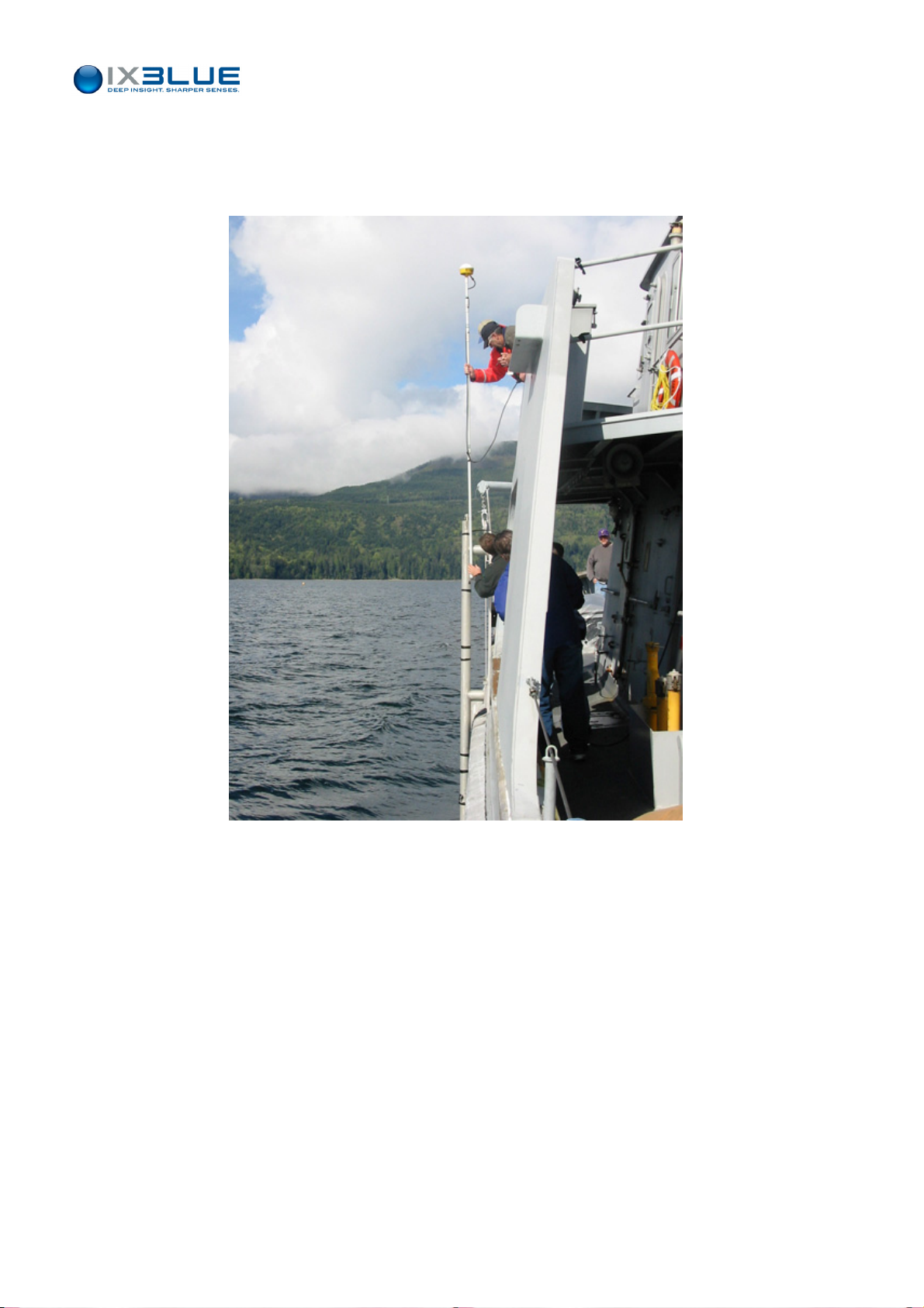
The integrated DGPS antenna has to be fixed (see Figure 27). You can use a mast (not
provided) to do it.
GAPS – User Guide
Figure 27 - DGPS antenna installation
Two configurations are possible:
• With the ship GPS (see config. 1 on Figure 24)
With the DGPS provided by iXBlue (see config. 2 on Figure 24)
•
II.5.1 INSTALLING AN EXTERNAL GPS
In this case, you must not use the Y-cable to be plugged to the GAPS. Plug your GPS
directly on the ECB via the GPS DB9 plug or on your Souriau socket of your acoustic
array cable if you do not use an ECB.
II.5.2 INSTALLING THE IXBLUE DGPS
The DGPS DB9 plug of the ECB is not used in this case. Plug the 10 m GPS cable on the
Y-cable then the DGPS.
MU-GAPS-AN-003 Ed. L – May 2012
32
Page 45
II.5.3 MEASURING THE GPS LEVER ARMS
GAPS – User Guide
GPS Antenna
Lever Arms
GPS Antenna
Above GAPS
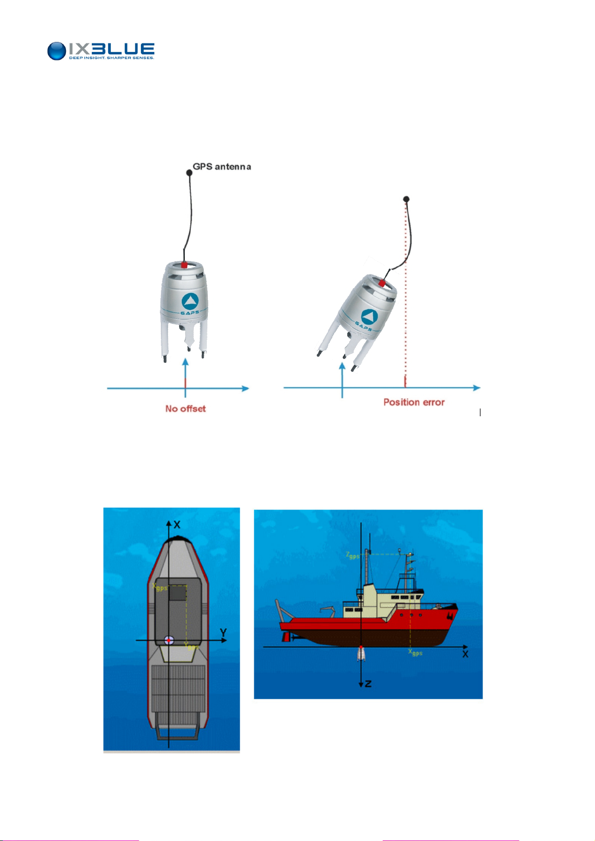
Even though it is designed to work in the vertical position, GAPS acoustic array can be
tilted if necessary and also be placed in the horizontal position.
To calculate the absolute position of a transponder, GAPS needs to know its own position.
This information is provided by the GPS, either the integrated or an external one. In both
cases, the offsets between the GPS antenna and the GAPS acoustic array must be
known.
When GAPS is tilted, the three offsets between the GPS antenna and the acoustic array
have to be entered accurately. When GAPS is in horizontal position, the axes are
inverted, the attitude outputs are then irrelevant.
There are 2 different solutions to install the GPS antenna with different implications on the
mounting of the acoustic array:
• GPS antenna right above GAPS
• GPS antenna not exactly above GAPS
Connected with a Rigid Link
This is typically when GAPS is mounted on a mast or held by a rigid pole.
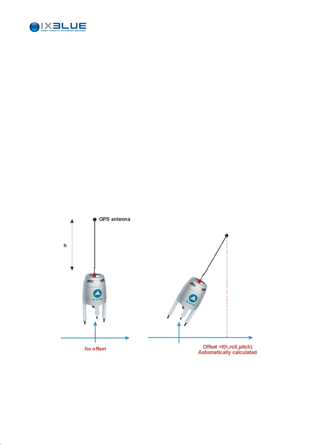
When GAPS is vertical, all the offsets between the GPS antenna and the acoustic array
are set to 0 except the height (h) which must be entered accurately in order to calculate
the position offset when the system attitude changes.
Figure 28 - Vertical GPS Antenna Lever Arm
MU-GAPS-AN-003 Ed. L – May 2012
33
Page 46
GAPS – User Guide
Connected with a flexible link
This is typically when GAPS is held by a rope.
In that case, the height value (h) must also be set to 0 (to avoid the calculation of the
offset). The accuracy of the positioning will decrease if the position of GAPS relative to the
GPS antenna changes.
GPS antenna
not above
GAPS
Figure 29 - Vertical GPS Antenna Lever Arm
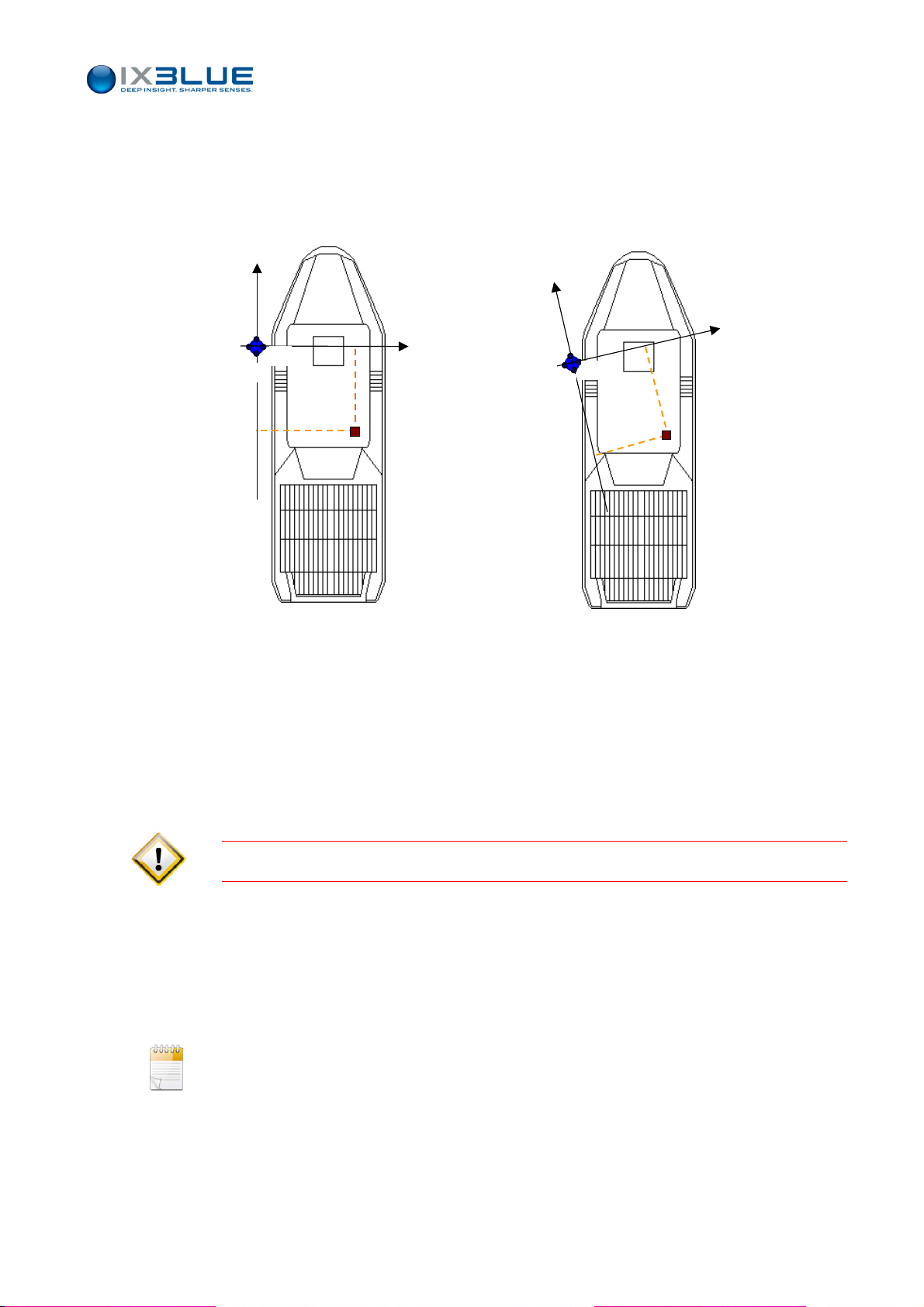
When the GPS antenna is not located right above GAPS, its position in the GAPS frame
has to be determined. The definition of these lever arms, Xgps, Ygps and, Zgps is given
in Figure 30.
Figure 30 -
GPS antenna Lever Arms (antenna not above GAPS)
MU-GAPS-AN-003 Ed. L – May 2012
34
Page 47
GAPS – User Guide
In this case, the heading of the acoustic array must be fixed and known. No matter if this
heading is not the same as that of the ship (yet it will have to be taken into account if
GAPS is also used as an onboard gyrocompass), but its value must be known in order to
calculate the position of the GPS in the GAPS reference frame (see Figure 31).
GAPS
GAPS
H3
H1
H4
H2
H3
H1
H4
H2
GPS
GPS
Figure 31 - Same headings (on the left) and different headings (on the right) for GAPS and ship
• If the GAPS H1-H2 axis is not parallel to the ship aft forward axis, two options are
possible to enter the GPS offsets with respect to the GAPS reference system:
• Enter the offset distances of the GPS with respect to the ship reference system shifted
above the GAPS antenna. Then enter the angular offsets of the GAPS reference
system with respect to the ship reference system using the antenna offsets tool box
window.
NTER THE OBSERVED OFFSETS VALUES AND NOT THE CORRECTION TO BRING TO THE OFFSETS
E
.
• Enter the distances offsets of the GPS antenna directly in the tilted GAPS reference
system
The closer GAPS is to the GPS, the better is the accuracy of the measurement of the
heading of the acoustic array.
It is the same for the roll and pitch if the GAPS is intentionally not in the vertical position.
Measure the position of the GPS reference point with respect to the reference frame
linked to the GAPS unit. Measurement is performed along the three axis Xgps, Ygps,
Zgps (see section I.4.2 for the definition of the GAPS reference frame).
quired precision on the lever arm is below 10 cm. See Figure 32.
The re
MU-GAPS-AN-003 Ed. L – May 2012
35
Page 48
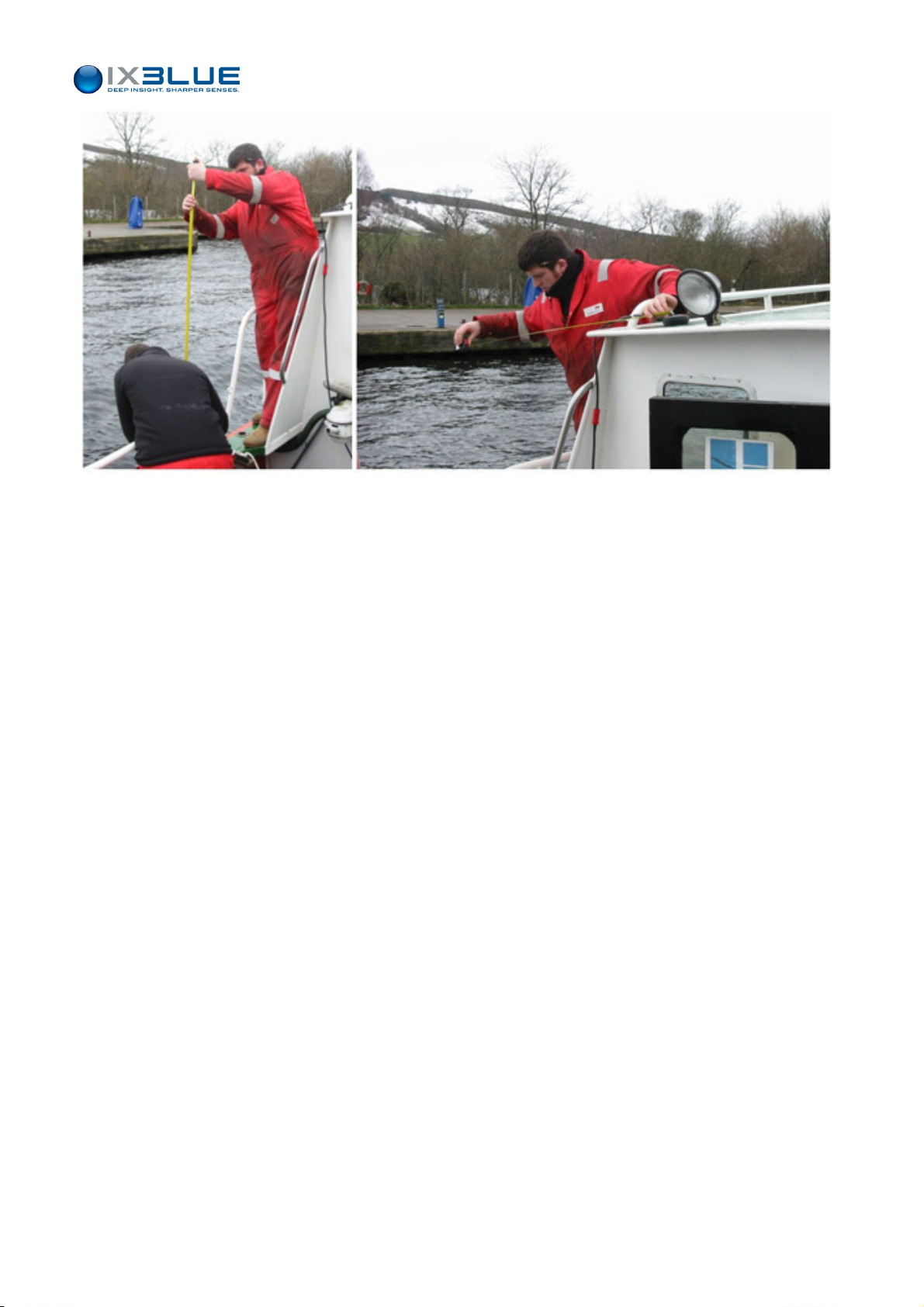
Figure 32 – Measure of GPS lever arms with respect to GAPS
GAPS – User Guide
II.5.4 SETTING THE GPS TIME
GAPS automatically updates its internal time. No menu in the MMI software enables you
to do it. Two cases can occur:
• Either the GPS is used as a reference. In this case, the GPS must be configured in
order to send ZDA frame (with a minimum rate of 1 s). As no PPS signal is used, the
precision reached is equal to ± 15 ms after the PPS signal
• Or if no ZDA frame is received by GAPS, the last time recorded by GAPS is used.
If the GPS do not deliver ZDA strings, then the time is taken from the GGA strings and the
precision of the positioning is still less than 1 second.
II.6 Installing a Transponder
The transponder is installed on the fixed or the mobile device that you are going to track.
The installation depends mainly on your equipment. Keep in mind that the transponder
head must be as much as possible
• Free from obstacles
• Directed towards the hydrophones of the GAPS antenna.
See installation examples in section II.2.3.
See se
ction IV.2.4 to bring the transponder in operation.
MU-GAPS-AN-003 Ed. L – May 2012
36
Page 49
GAPS – User Guide
III C
ONFIGURING
GAPS System is controlled by a user PC on which the Man Machine Interface software is
installed. All its functionalities are described in this section.
GAPS
III.1 Installing the Man Machine Interface
Required
environment
To set GAPS, the Man Machine Interface software provided with the system must be
installed on a PC.
The minimum PC configuration must be:
• Pentium III or Celeron 800 MHz
• 512 Mo RAM
• 20 Mb Hard Disk
• 1024 x 768 screen (the screen must be configured with a character size of 96 ppp)
• Microsoft Windows ™XP, VISTA and SEVEN
The installation of the Man Machine Interface cannot be achieved elsewhere than in the
Procedure
Step Action
5.
6.
7.
C:/Program Files/IXSEA folder. In foreign versions of the operating system, the
C:/Program Files folder may not exist. Please make sure to create it before running
the installation procedure.
Insert the MMI software CD-ROM in the CD-ROM drive.
The installation should start automatically otherwise double click on Setup in the CD-
ROM directory.
Follow the instructions displayed on screen.
Once the installation is completed, an IXSEA\GAPS MMI directory is created in the
default file C:/program files on your computer.
End of procedure.
On Windows SEVEN and VISTA, make sure to edit the security properties of the iXSea
folder and all sub-folders so writing in these folders is allowed.
MU-GAPS-AN-003 Ed. L – May 2012
37
Page 50
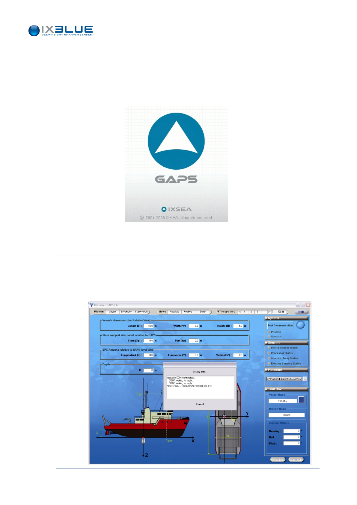
III.2 Overview of the Man Machine Interface
III.2.1 STARTING THE MAN MACHINE INTERFACE
Once the MMI installation is completed and when you have achieved all connections
between the devices, you can start the MMI Software.
GAPS – User Guide
Procedure
Step Action
1.
Figure 33 – Starting GAPS MMI, launching window
From Start menu, select Programs/ GAPS MMI/Man Machine Interface Software.
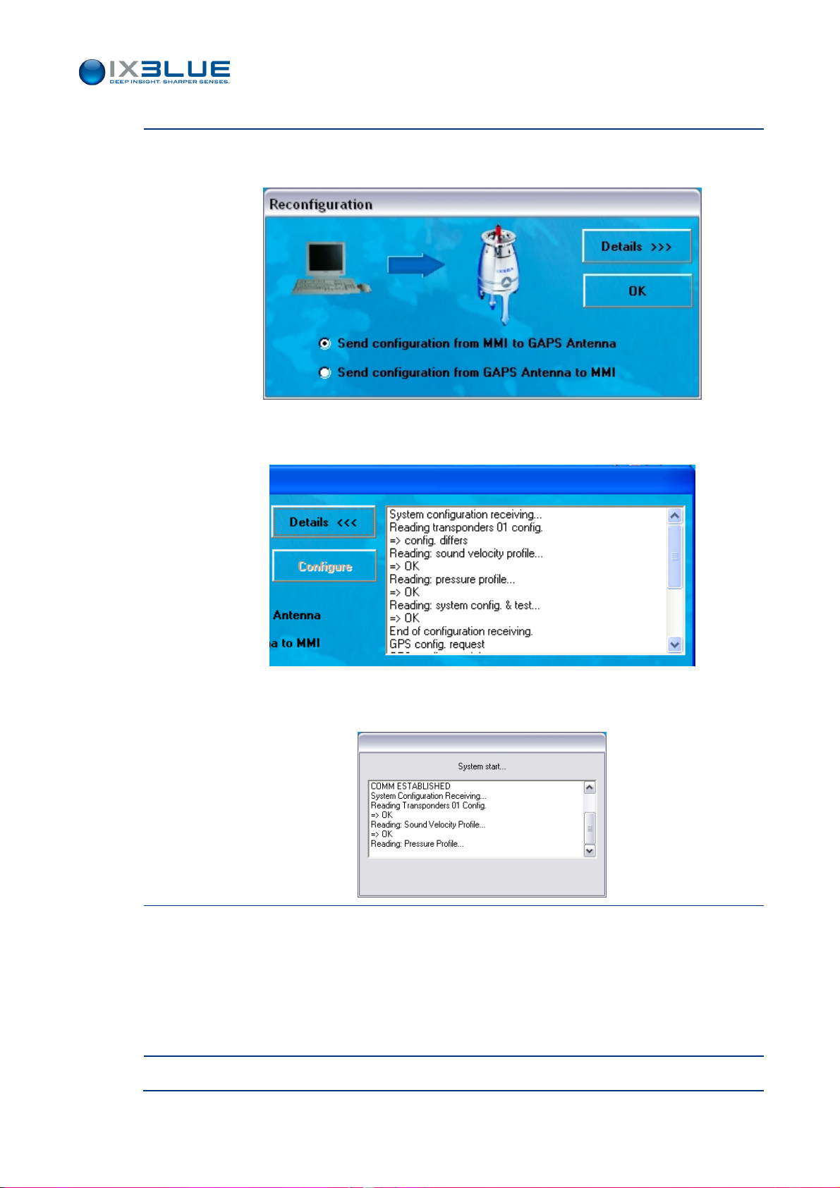
The MMI is started. The Communication ports of the PC are scanned by MMI to
recognize which devices are connected.
• If GAPS is not connected, the following window appears:
MU-GAPS-AN-003 Ed. L – May 2012
38
Page 51
Step Action
• Otherwise, if GAPS is connected and if both configurations between GAPS and
the MMI are different, the following dialog box appears:
In this case, you can know for which parameters the configurations differ by clicking on
Details button:
GAPS – User Guide
• Otherwise, if GAPS is connected and if the configurations of the GAPS and the
MMI are the same, the following window appears:
2.
If needed, choose between the MMI or GAPS configuration.
• If GAPS is not active, the system button located in the upper right side of the
main window is labeled ‘START Tracking’ and the associated light is blue
• If GAPS is active, the system button located in the upper right side of the main
window is labeled ‘STOP Tracking’ and the associated light is green
3.
End of procedure.
MU-GAPS-AN-003 Ed. L – May 2012
39
Page 52
III.2.2 MAIN WINDOW
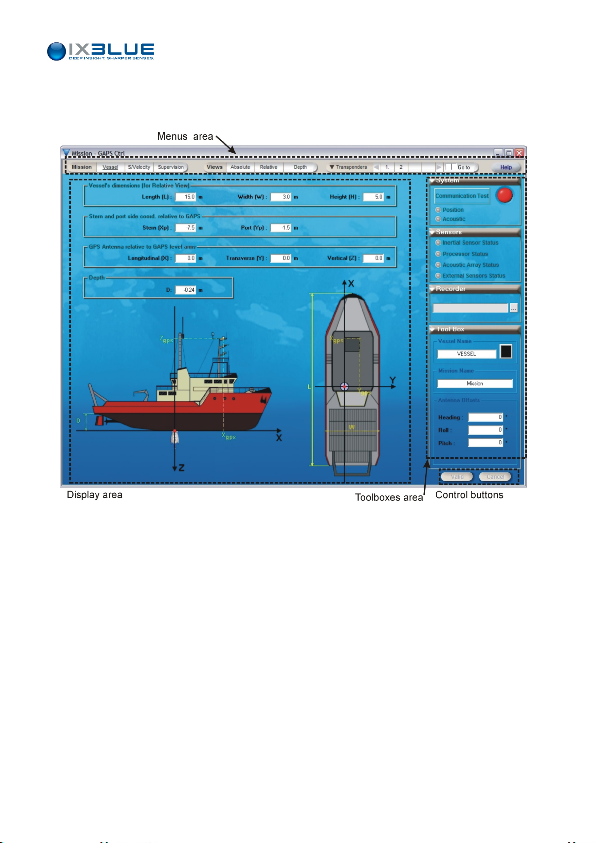
MMI software always opens with Vessel tab selected under the Mission menu (see
Figure 34).
GAPS – User Guide
Figure 34 - M
ain MMI Window
This main MMI window is divided into four areas:
• Menu bar: it enables to access the main menus and Help file.
Mission menu: it enables to configure the system and the interface
parameters (see section III.3.2) and, to enter the sound velocity profiles (see
ction III.3.9)
se
Views menu: to display the real time data either in a geographic reference
frame (see section Figure 44), or in a ship dependent frame (see Figure 45) or
in a time-de
Transponder menu: to add, define, modify and, suppress the devices you are
pth frame (see Figure 46)
tracking with GAPS (see section III.3.10)
The Tool Boxes area: these boxes enable you to monitor your mission.
•
System box: see section III.4.5 for more details.
Sensors box: see section III.4.5 for more details.
MU-GAPS-AN-003 Ed. L – May 2012
40
Page 53

GAPS – User Guide
Recorder box: it enables to select the folder where the real time data will be
stored (see section III.5).
Tool Box: the content of this box depends on the selected menu and/or on the
selections made in the above boxes.
• Control buttons
Valid button: to validate the modifications entered and to save them in the
GAPS.
Cancel button: to cancel the modification you have entered.
• Display area: The display area is menu dependent. It can display vessel parameters
(see section III.3.2), real time data display (see section III.4.1), sound velocity profile
e section III.3.9) etc.
(se
III.2.3 C
OLOR CODE
When you modify some parameters in the different windows or toolboxes, the
corresponding menu titles are set to red. This color code means that modifications have
been made but not applied yet in the MMI and/or GAPS itself. Use the Valid button to
apply them.
UNCTIONAL PARAMETERS CANNOT BE VALIDATED WHEN
F
MODIFY FUNCTIONAL PARAMETERS WHILE
.G., ‘STOP
E
Y
OU HAVE TO STOP TRACKING BEFORE APPLYING THE MODIFICATIONS
TRACKING’ LABEL, DISPLAYS A RED CONTOUR AND IT IS FLASHING
GAPS
IS OPERATING, THE COMMUNICATION BUTTON
GAPS
IS OPERATING. WHEN YOU
.
.
MU-GAPS-AN-003 Ed. L – May 2012
41
Page 54
III.3 Configuring GAPS
GAPS – User Guide
III.3.1 C
Window
Access
Parameters
ONFIGURING THE SURVEY PARAMETERS
Before running the survey, you have to define the mission parameters.
To configure and/or modify the mission parameters, select the Vessel tab under the
Mission menu.
In the displayed window (see Figure 35 and Figure 36), you have to define:
•
In the associated tool box:
The Vessel Name and color for the real time data is displayed. This setting is
optional.
The Mission Name. This setting is optional.
The angular offsets of the GAPS called antenna offsets (Heading, Roll and
Pitch). Normally GAPS must be in vertical position and oriented so that the
hydrophone H1 is towards the bow (see Part 2 of this manual). In such a
configuration, the angular offsets are set to zero. If GAPS is tilted so that the
angles are greater than a few degrees then you have to enter these angular
offset.
RICK TO DETERMINE THE ANGULAR OFFSETS
T
:
W
HEN THE SHIP IS AT A 0° HEADING, 0° ROLL AND 0° PITCH, THE VALUES AND SIGNS OF THE
ANGULAR OFFSETS CAN BE FOUND IN THE
V
IEWS WINDOWS IN THE ATTITUDE FIELDS
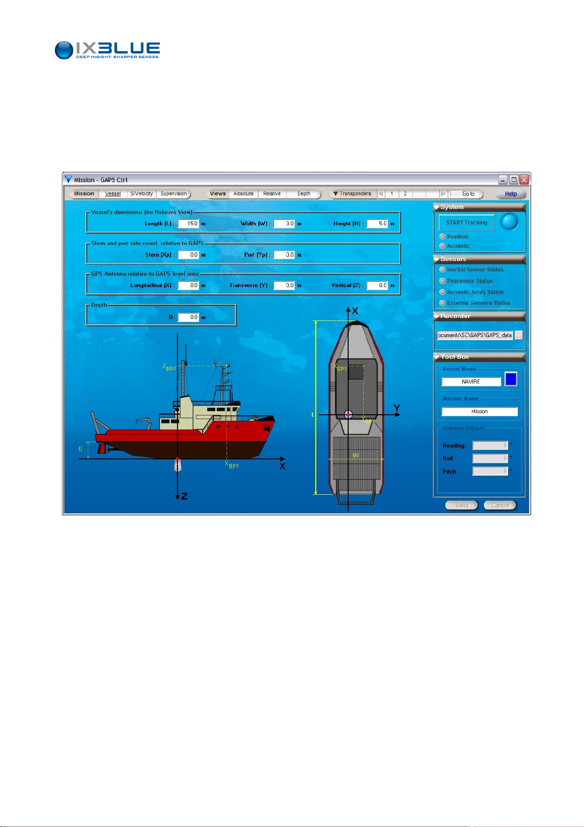
• In the Display area, the following values are only used in the relative views. They do
not affect positioning.
The vessel dimensions: the Length, Height and Width values (only used in
the relative views)
The location of the ship stern and port side with respect to GAPS: Stern (Xp),
Port (Yp).
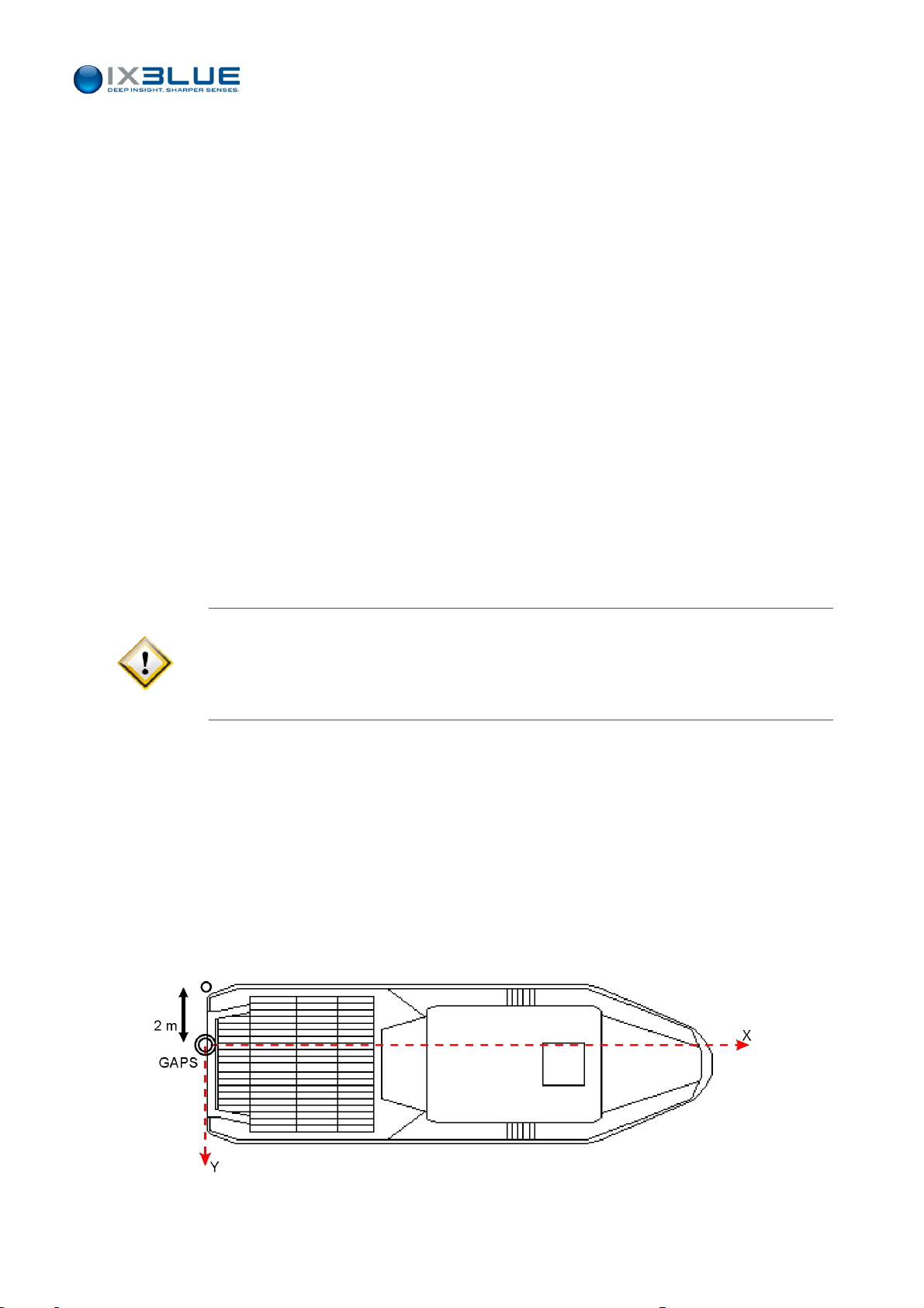
Example: For a GAPS located at the stern level at 2 m of the port side (inside the ship),
these values are the following:
Xp = 0 m , Yp = -2 m
.
Figure 35 - Position of the stern port point with respect to GAPS
MU-GAPS-AN-003 Ed. L – May 2012
42
Page 55
GAPS – User Guide
The lever arms of the GPS antenna with respect to GAPS: Longitudinal (X),
Transverse (Y), Vertical (Z) values. These parameters affect directly the
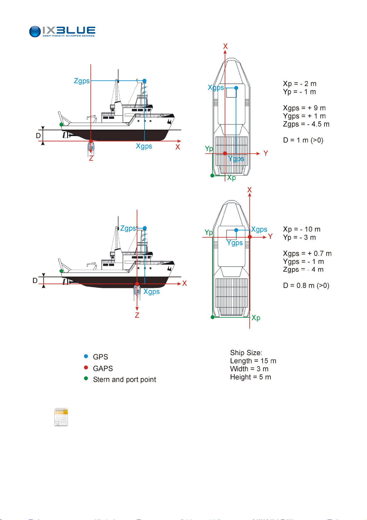
positioning. The further the GPS is from GAPS, the bigger the error in the lever
arms will be. See Figure 37 for numerical examples.
The draft D of the ship relative to GAPS.
Figure 36 - Vessel Window
MU-GAPS-AN-003 Ed. L – May 2012
43
Page 56
GAPS – User Guide
Figure 37 – Examples of Numerical values for the ship dimensions and the GPS offsets with respect to GAPS
All offsets and distances are in meters and signed with respect to the axis drawn in the
window.
MU-GAPS-AN-003 Ed. L – May 2012
44
Page 57

Procedure
Step Action
1.
2.
GAPS – User Guide
In the Vessel Dimensions display area, fill in the vessel dimensions by clicking on the
corresponding fields.
When you click on a distance field that you want to fill, the style of the associated line in
the ship representation below is highlighted in order to be easily identified and to avoid
confusion between distances.
The drawing of the vessel window does not change. The Vessel tab label turns red.
In the Stern and Port side coord. Relative to GAPS display area, fill in the ship port
side and stern with respect to GAPS by clicking on the corresponding fields.
When you click on Xp or Yp field that you want to fill, the style of the associated line in
the ship representation below is highlighted in order to be identified and avoid confusion.
In the relative view, the reference frame corresponds exactly to the position of GAPS
with respect to the ship.
3.
In the GPS Antenna relative to GAPS lever arms display area, fill in the GPS lever
arms by clicking on the corresponding fields.
When you click on a lever arm field that you want to fill, the style of the associated line in
the ship representation below is highlighted in order to be easily identified and to avoid
confusion between lever arms.
4.
In the Depth display area, fill in the depth of the antenna by clicking on the D field.
5.
In the associated tool box, enter the following optional parameters
• The Vessel Name
The entered vessel name will appear in the different available views.
• In the associated toolbox, click on the color button to choose the color of
the symbol representing the vessel in the real-time data displays.
A color palette is displayed.
• The Mission Name
The mission name appears in the window title.
6.
Enter the GAPS angular offsets: Heading, Roll and Pitch. All values are expressed in
degrees.
7.
Click Valid button to validate the modifications if GAPS is not operating otherwise stop
GAPS before clicking the Valid button.
8.
End of procedure.
MU-GAPS-AN-003 Ed. L – May 2012
45
Page 58

III.3.2 CONFIGURING THE SYSTEM PARAMETERS
Before running the survey, you have to define all the parameters of the different interfaces
of GAPS, MMI software, serial link, GPS, Inertial sensor, processor, acoustic array and
output.
GAPS – User Guide
Window
Access
Version
Choice
Parameters
To configure and/or modify the GAPS System parameters, select the Supervision tab
under the Mission menu.
When the MMI is not connected to a GAPS unit, two radio buttons appear on the right of
the antenna display. These two radio buttons allow the user to select the GAPS version:
• Titanium Version V
and V2: not described in this document.
0
• Carbon Version: this system is described in the present manual.
When the MMI is connected to a GAPS unit, the MMI software switches automatically
between the two versions.
In the displayed window (see Figure 38), you can configure or display:
The MMI serial link parameters: port number, baud rate (maximum 57,600 bauds),
•
parity, stop bit
• The MMI parameters: alarm sound and automatic recording of data files
• The GPS parameters: baud rate (maximum 57,600 bauds), protocol, parity and, stop
bit
• The processor parameters: position rate delivery and acoustic recurrence
• The acoustic array parameters: Interrogation Frequency, Signal/Noise Ratio
parameters
• The output parameters: protocol (which kind of data are delivered), period, Baud rate
(maximum 57,600 bauds), Parity, Stop bit
MU-GAPS-AN-003 Ed. L – May 2012
46
Page 59
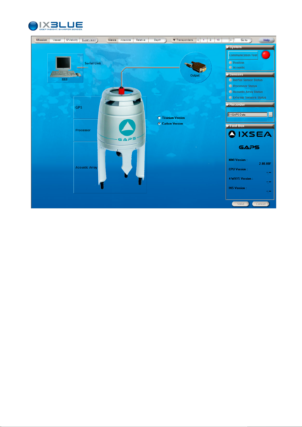
GAPS – User Guide
Figure 38 - Supervision Window
In the Supervision window, the Tool Box displays some versions about the system
components: MMI software version, CPU version, 4Ways version and INS version.
MU-GAPS-AN-003 Ed. L – May 2012
47
Page 60
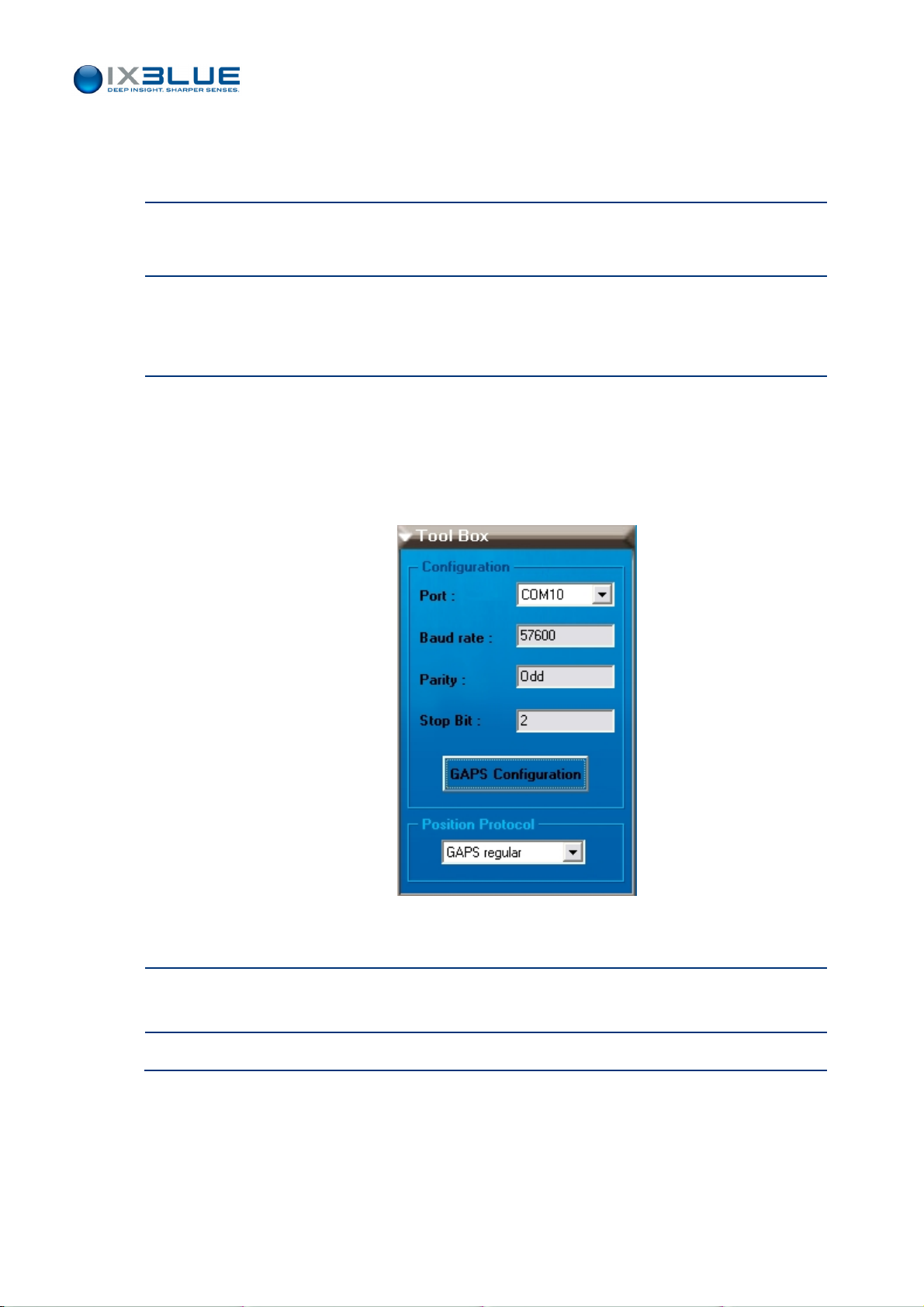
III.3.3 CONFIGURING THE SERIAL LINK
Step Action
1.
In the Supervision display area (see Figure 38), click on Serial Link label.
The associated tool box appears.
2.
In the associated toolbox, you can reload in GAPS the configuration displayed in MMI by
clicking on GAPS Configuration.
The serial link parameters already saved are then displayed.
3.
In the Tool Box, if necessary
• Choose the Port number by selecting it in the scrolling list
• Only on iXBlue customer support request, choose the Position Protocol: GAPS
Extended (only for factory usage). By default, it is the protocol GAPS Regular
that it is used.
GAPS – User Guide
In the Display area, the Serial Link label turns red to remind you that you have to
validate your choices.
4.
Click Valid button to validate the modifications if GAPS is not operating otherwise stop
GAPS before clicking the Valid button.
5.
End of procedure.
MU-GAPS-AN-003 Ed. L – May 2012
48
Page 61
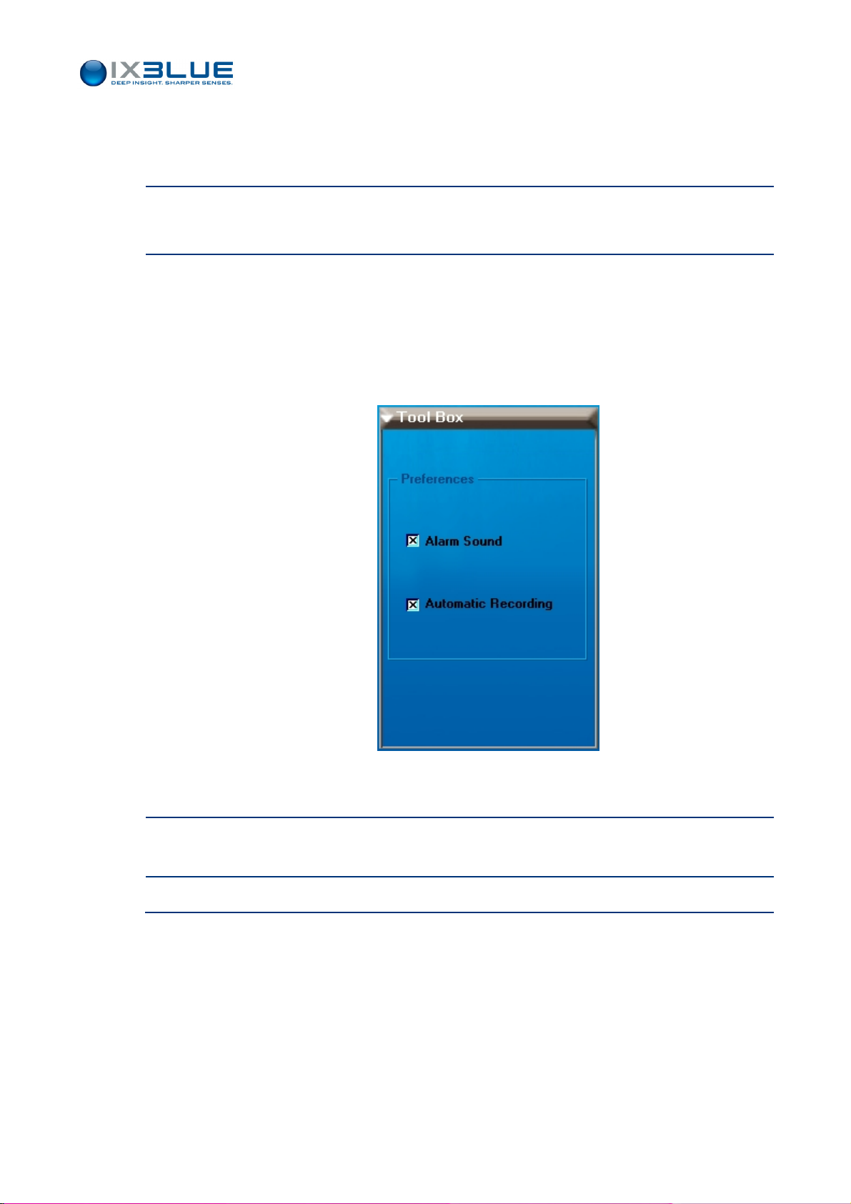
III.3.4 CONFIGURING THE INTERFACE PARAMETERS
Step Action
1.
In the Supervision display area (see Figure 38), click on MMI label.
GAPS – User Guide
The asso
2.
In the tool box, if needed
ciated tool box appears.
• Choose to be informed by a sound when any status light of the sensor tool box
becomes red: select the Alarm Sound check box.
• Choose to record automatically the real time data: select Automatic Recording
check box.
In the Display area, the MMI label turns red to remind you that you have to validate your
choices.
3.
Click Valid button to validate the modifications if GAPS is not operating otherwise stop
GAPS before clicking the Valid button.
4.
End of procedure.
MU-GAPS-AN-003 Ed. L – May 2012
49
Page 62
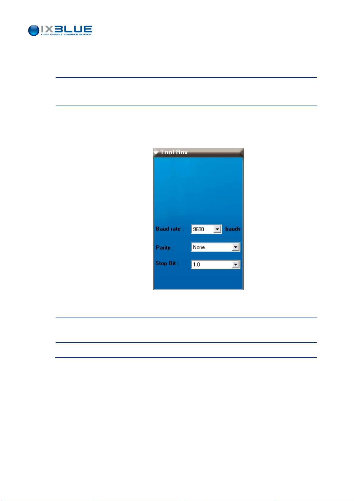
III.3.5 CONFIGURING THE GPS PARAMETERS
Step Action
1.
In the Supervision display area (see Figure 38), click on GPS label.
GAPS – User Guide
The asso
2.
In the Tool Box, choose
ciated tool box appears.
• The baud rate by selecting it in the scrolling list (maximum 57,600 bauds)
• The Parity and Stop Bit by selecting them in the corresponding scrolling lists.
In the Display area, the GPS label turns red to remind you that you have to validate your
choices.
3.
Click Valid button to validate the modifications if GAPS is not operating otherwise stop
GAPS before clicking the Valid button.
4.
End of procedure.
MU-GAPS-AN-003 Ed. L – May 2012
50
Page 63
III.3.6 CONFIGURING THE PROCESSOR PARAMETERS
You can choose the rate of the acoustic ping and the types of acoustic mode:
• Internal Fixed – it needs to set up the recurrence in the edit box at the bottom of the
dialog box. The minimum value is 1 s. The recurrence obey the following inequalities:
D
R +> 1*
max
TAT
in responder mode
500,1
D
R +> 2*
max
TAT
in transponder mode
500,1
GAPS – User Guide
R is the recurrence, D
and TAT is the turn around time. See Table 10.
Table 10 – Maximum worki
Maximum working distance (m)
Responder mode Transponder mode
1 1,365 682
2 2,865 1,432
3 4,365 2,182
4 5,865 2,932
5 7,365 3,682
Recurrence (s)
6 8,865 4,432
is the distance between the antenna and the transponder
max
ng distance versus recurrence with a TAT = 90 ms
MU-GAPS-AN-003 Ed. L – May 2012
51
Page 64
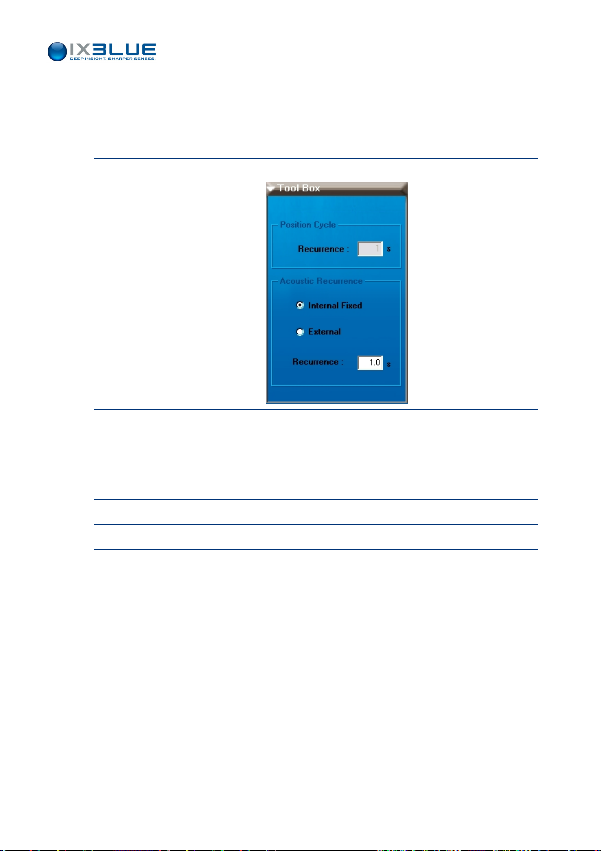
Procedure
Step Action
GAPS – User Guide
• External – coming from the synchro IN. The recurrence used may be slow. It must
always be greater than 1 s. When the position cycle is lower than the acoustic
recurrence, the INS helped with the GPS predicts the points between two pulses.
1.
In the Supervision display area (see Figure 38), click on Pr
2.
In the Tool Box, if needed
• Enter the delivery rate in Recurrence in [second] if Internal Fixed is selected.
ocessor label:
• Otherwise choose External.
In the Display area, the Processor label turns red.
3.
Click on Valid if GAPS is not operating otherwise stop GAPS before clicking on Valid.
4.
End of procedure.
MU-GAPS-AN-003 Ed. L – May 2012
52
Page 65
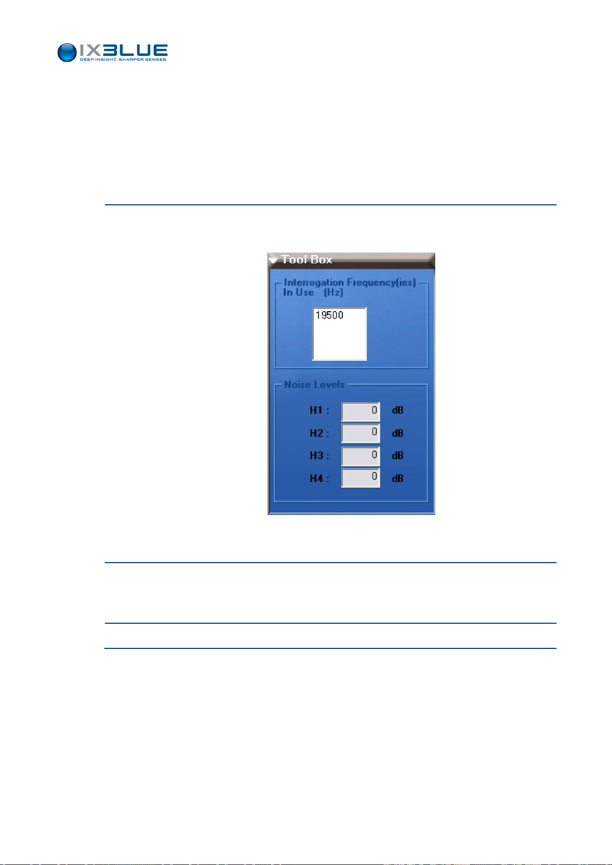
III.3.7 CONFIGURING THE ACOUSTIC ARRAY PARAMETERS
There is no configuration to perform for the antenna, however there is the opportunity to
check the NIS (Noise Isotropic Spectrum) on each hydrophone of the antenna. It gives an
idea of the current acoustic noise in the sea and allows to quickly find out if a hydrophone
is damaged.
Step Action
1.
In the display area, click on Acoustic Array label.
The associated tool box appears.
GAPS – User Guide
The Interrogation frequency used is displayed according to the transponder
configurations.
2.
Check the NIS on each hydrophone. Verify that the given values are homogeneous. In
the opposite, the hydrophone giving a strongly different value than the others is probably
faulty.
3.
End of procedure.
MU-GAPS-AN-003 Ed. L – May 2012
53
Page 66

III.3.8 CONFIGURING THE OUTPUT PARAMETERS
In this toolbox can be set up the parameters of the additional output data: which kind of
data and the associated port configuration.
The list of protocols available is (“none” means no Output):
For the string containing the transponder position:
• GAPS Standard
• GAPS Light
• HiPap HPR 418 BCD (Rev C) Mobile
• HiPap HPR 418 BCD (Rev C) Fixed
• HiPap HPR 400
• Nautronix ATS II
• POSIDONIA 6000
• IXSEA USBL-INS 1
• IXSEA USBL-INS 2
GAPS – User Guide
• GPGGA (GAPS antenna) + VTG
For the strings containing information relative to the GAPS antenna but NO position of the
transponder:
• GyroCompass
• Halliburton
• Navigation
• HEHDT
• Phins Standard
• Simrad EM
• Autosub
• Post processing (for factory use only)
MU-GAPS-AN-003 Ed. L – May 2012
54
Page 67
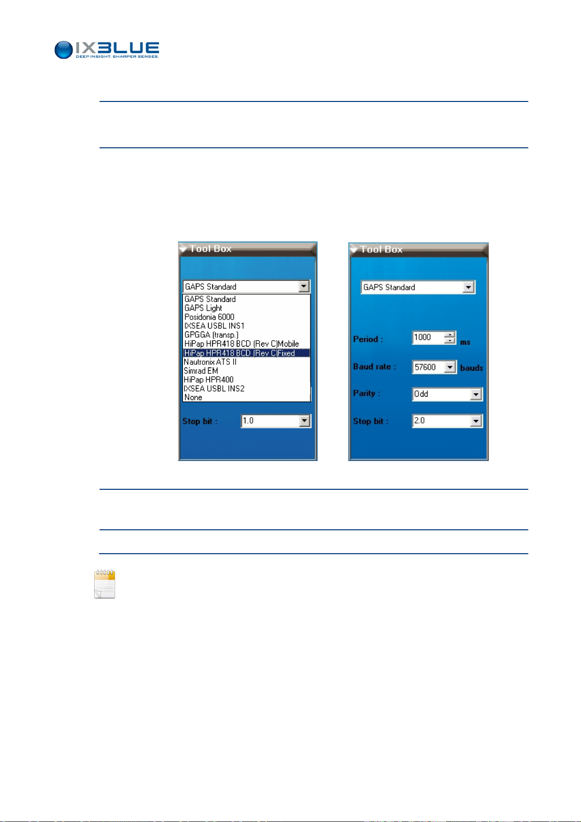
Procedure
Step Action
1.
2.
GAPS – User Guide
In the Supervision display area (see Figure 38), click on Ou
tput label.
The associated tool box appears.
• Choose the Protocol by selecting it in the scrolling list
• Enter the real time data Period in [ms] (see Note below)
• Choose the Baud rate by selecting it in the scrolling list (maximum 57600 bauds)
• Choose the Parity and Stop bit by selecting them in the scrolling lists.
In the Display area, the Output label turns red to remind you to validate your choices.
3.
Click Valid button to validate the modifications if GAPS is not operating otherwise stop
GAPS before clicking the Valid button.
4.
End of procedure.
If you select a protocol that uses raw positions (such POSIDONIA 6000, IXSEA USBL INS
1, IXSEA USBL INS 2), the position rate cannot be set as it is the rate of these raw
positions that applies. In this case, the field Period has no meaning.
MU-GAPS-AN-003 Ed. L – May 2012
55
Page 68
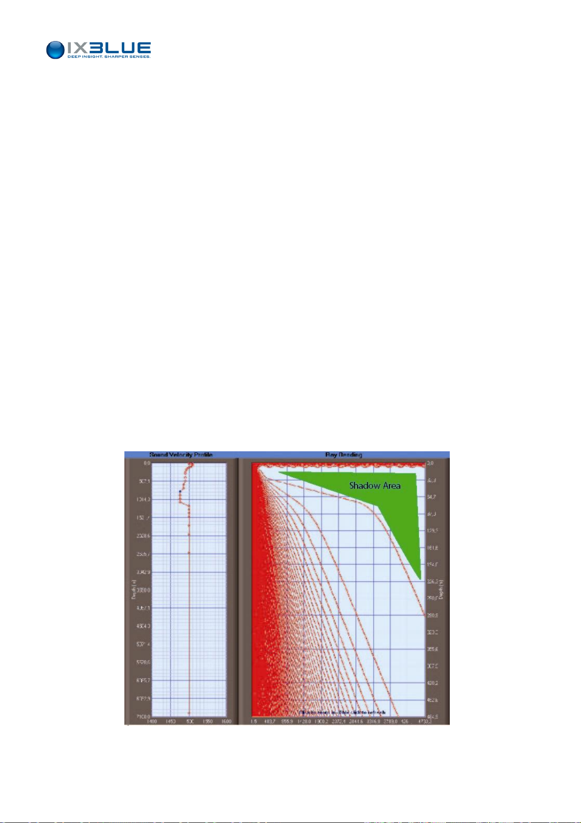
III.3.9 DEFINING A SOUND VELOCITY PROFILE
GAPS – User Guide
Entering a
Velocity
Profile
Window
Access
To compute the transponder position, the ray bending has to be taken into account. A
sound velocity profile (SVP) must be defined.
You can either manually enter (point by point) the velocity values (between 1400 and
1600 m/s) with respect to immersions or import a sound velocity profile file. In this case,
the file must be a list of
Immersion depth (integer in [meter]), Celerity (integer in [m/s])
comma separated [CR/LF]
e.g., ‘2000,1500’ (At 2,000 meters depth the sound velocity is 1500 m/s)
in a text format. Imperatively, this file must contain a maximum of 55 couples (depth,
celerity) classified in increasing depths. If there are more than 55 data, the last ones are
lost.
The immersion depths can be modified manually in the file. The immersion depths are
transformed into pressure values by the MMI before transmitting them to the GAPS.
The first depth value must be ‘0’. The last depth value cannot be greater than 7,000.
This input file or the manually input points can be saved in another file.
To enter a sound velocity profile, select the S/Velocity tab under the Mission menu.
Window
Description
The corresponding window (see Figure 39) appears. The Sound Velocity Profile and Ray
Bending a
reas may be empty if you have not defined a sound velocity profile yet.
Figure 39 - Sound Velocity View Window
MU-GAPS-AN-003 Ed. L – May 2012
56
Page 69
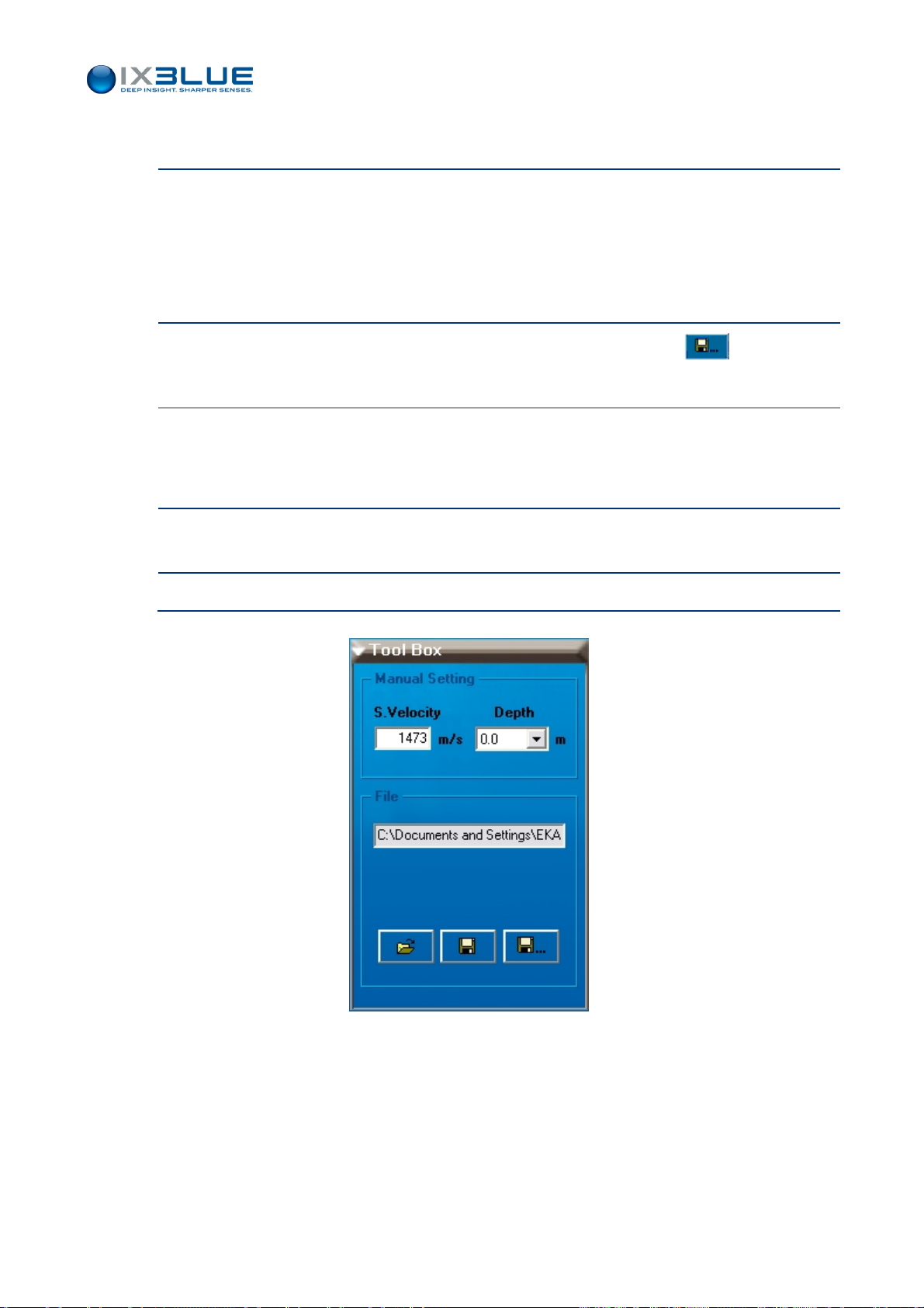
Manually Entering a Sound Velocity Profile
Step Action
1.
Select the S/Velocity tab under Mission menu in the toolbox (see Figure 40), type in the
GAPS – User Guide
S.Velocit
y value for each immersion depth appearing in the Depth field. Validate each
sound velocity input by pressing the [enter] key.
The sound velocity profile updates at each input. The depth value increments and you
are ready to enter the sound velocity corresponding to the next depth value.
2.
You can save the profile you have defined in step 1. by clicking on button.
The Save as window appears.
3.
Choose the folder where you want to save the sound velocity profile, type in the filename
and click OK.
Your sound velocity profile is saved in a text file with the format described above.
4.
Click Valid button to validate the modifications if GAPS is not operating otherwise stop
GAPS before clicking the Valid button.
5.
End of procedure.
Figure 40 – Sound Velocity Toolbox
MU-GAPS-AN-003 Ed. L – May 2012
57
Page 70
Importing a Sound Velocity Profile File
Step Action
1.
Select the S/Velocity tab under Mission menu in the toolbox (see Figure 40), click on
button to import a file.
GAPS – User Guide
Looking for
Shadows
Areas
The Ope
2.
Select your sound velocity profile file and click OK.
n… window appears.
The sound velocity profile appears in the Display area.
3.
You can modify some sound velocity values (see the previous procedure) and then save
the modified file under the same name (by clicking ) or under another one (by
clicking on )
Your sound velocity profile is modified.
4.
Click Valid button to validate the modifications if GAPS is not operating otherwise stop
GAPS before clicking the Valid button.
5.
End of procedure.
Once the velocity profile is input, you can compute, by double clicking on the right graph,
the path that a sound ray would take with this velocity profile. The graph is computed for
angles between 0° and 90° at a 1° step. The path is computed from the GAPS to the
Zooming
III.3.10 C
Defining a
Transponder
transponder. This allows you to see if there are areas where you could not see your
mobile (shadow areas, see Figure 39). Note that the horizontal an
d vertical scales are not
the same when looking at angles on the graph. You can zoom on the data by drawing a
rectangle with the left mouse button down over the area of your choice.
You can zoom on the area of your choice on the graph. Left-click on one of the graphs
and draw a rectangle. Double click to come back to the full visualization.
ONFIGURING THE TRANSPONDER PARAMETERS
You can add a new transponder from a list or copy the settings of a transponder already in
defined to the new one being entered. The available transponders are iXBlue–MT8 or
ET8, iXBlue-MT9, iXBlue-BT8, ORE-435xB.
HE IXBLUE
T
S
ELECT AN IXBLUE
PARAMETERS AVAILABLE FOR THE
-MT9
IS CONFIGURED VIA THE CONFIGURATION WINDOW OF THE IXBLUE
-MT8
TRANSPONDER IN ORDER TO ADD A IXBLUE
MT8
ARE APPLIED TO YOUR
-MT9. T
MT9
TRANSPONDER
HE CONFIGURATION
.
-MT8.
MU-GAPS-AN-003 Ed. L – May 2012
58
Page 71

GAPS – User Guide
Access
The creation process of a new transponder displays successively two different windows:
• The New transponder window (see Figure 41): access it by selecting Ne
w… option
under Transponders menu
• The transponder view in the Display area of the Main MMI window:
• See Figure 41 for a multi-frequency transponder: access it once you have clicked
Crea
te button in the New Transponder window.
These windows contain:
• New Transponder window: It contains the transponder ID, its Manufacturer and
Type to define. You can copy the settings of an existing transponder to create a new
one by selecting Copy from check box and selecting its ID. The transponder ID is the
main transponder identifier in the MMI.
• Transponder view: The tool box enables you to set the transponder in the ‘in use’
state (i.e. to display it in the different views), to choose its display color for the
absolute, relative and depth view and, to know and possibly modify its serial number,
ID one and name. The display area contains:
The Transmit parameters are used to define the MFSK code, the Blanking
Time i.e., the time during which no transmission is possible just after having
transmitted and, the Turn around Time i.e., the delay between the reception
of the triggering signal and the transmission of the reply.
The Receive parameters are used to define the Individual Interrogation
Frequency (IIF) and if the transponder is used in Responder or Transponder
mode (see Part 1 of this manual).
Filtering for is used to define the filter to use: None, Towed Fish (specific
filter adapted to mobiles, predictable motion), ROV/AUV (specific filter adapted
to mobiles, unpredictable motion), Fixed Transponder (specific filter adapted
to fixed transponders, no motion).
Pressure sensor: None, Serial link, Acoustic or External with the accuracy
in decimeter (for example for a pressure sensor given for 0.1% of the depth
that would be used at a 3,000 m – depth, you would enter 30 dm in the
accuracy field).
You can define up to 127 transponders.
HE TRANSPONDER CAN BE TRACKED ONLY WHEN IT IS ‘IN USE’.
T
Y
OU CANNOT USE TWO (OR MORE) TRANSPONDERS WITH THE SAME
SIMULTANEOUSLY
.
IIF
AND
MFSK
CODE
MU-GAPS-AN-003 Ed. L – May 2012
59
Page 72
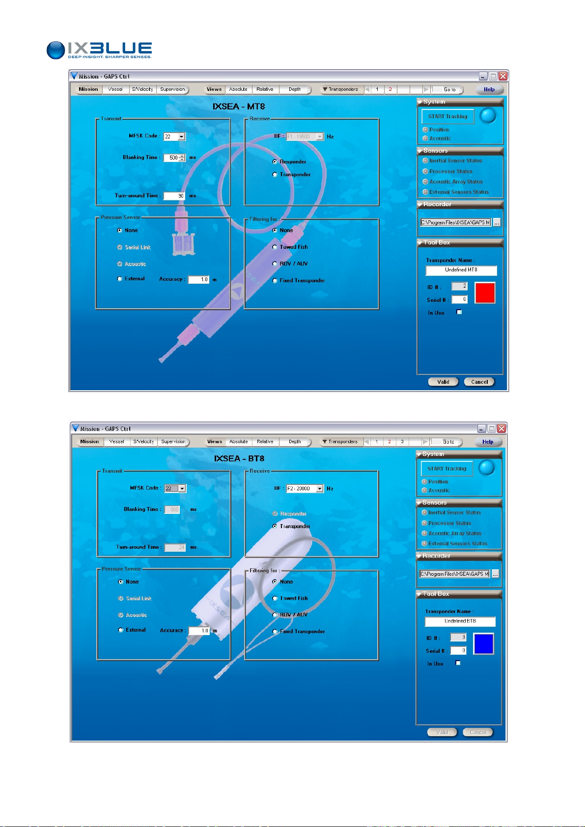
GAPS – User Guide
Figure 41 - Transponder MT8 view
Figure 42 - Transponder BT8 view
MU-GAPS-AN-003 Ed. L – May 2012
60
Page 73
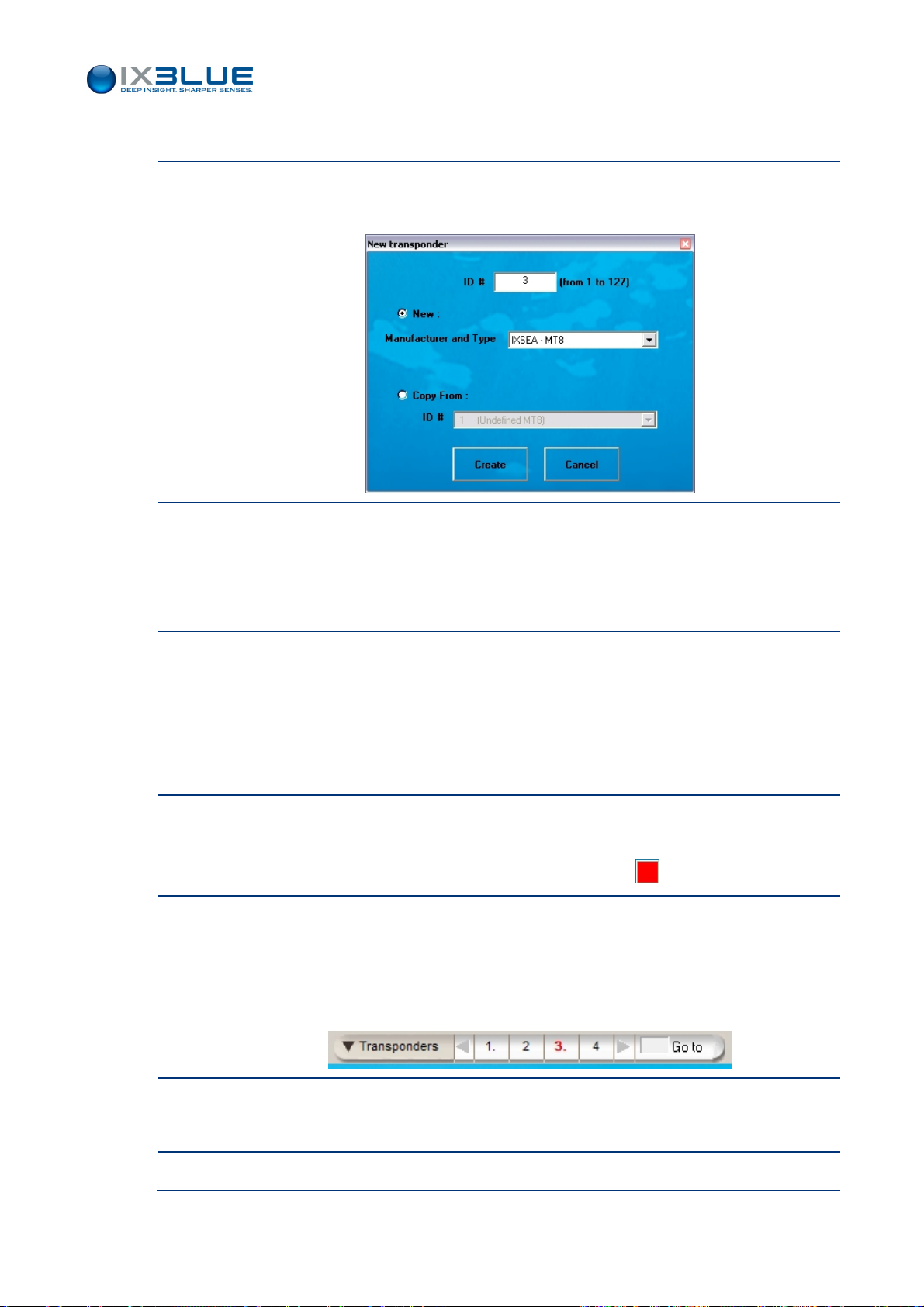
Procedure
Step Action
1.
GAPS – User Guide
Under Transponders menu select New… option to define the new transponder.
The New Transponder window opens:
2.
In the New transponder window, you can
• Either select the Manufacturer and Type after having selected New check box.
• Or define the new settings by selecting existing ones: select Copy from check box
and choose the transponder ID to copy in the scrolling list.
3.
Click Create button to create the new transponder.
The transponder settings are displayed in the Display area of the main MMI window. It
contains default settings for a new transponder and the settings of an existing one in
case of a copy.
The transponder ID appears in the transponder list (near the Transponders menu).
4.
You can
• Modify the settings
• Change the transponder display color by clicking on
5.
Select In Use check box to track the transponder and to see this transponder in the
different views.
The transponder ID in the transponders list (near the Transponders menu) turns red
and a “.” appears after the transponder ID number in the transponder menu:
6.
Click on Valid if GAPS is not operating otherwise stop GAPS before clicking on Valid.
The transponder ID in the list (besides the Transponders menu) turns black.
7.
End of procedure.
MU-GAPS-AN-003 Ed. L – May 2012
61
Page 74
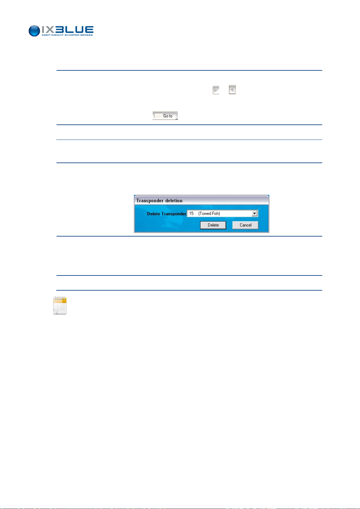
GAPS – User Guide
Checking/
Editing
Step Action
Suppressing
Step Action
• If its ID is displayed in the Transponder list near the Transponders menu, click on it.
1.
• Otherwise scroll in the ID number using the or button to find it and then select
it by clicking. On its ID number.
• Or use the Go to box to enter directly its ID.
2.
End of procedure.
1.
Select Suppress… option in the Transponders menu.
The Transponder deletion window appears:
Sorting
2.
Select the transponder you want to delete in the Delete Transponder scrolling list and
click Delete.
The transponder ID disappears from the transponder list near the Transponders menu.
3.
End of procedure.
The transponder cannot be deleted when “in use” and /or when GAPS is tracking.
You can sort the transponders list by chronological or numerical order by selecting
Chronological list or Numerical list (on the ID) in the Transponders menu.
MU-GAPS-AN-003 Ed. L – May 2012
62
Page 75
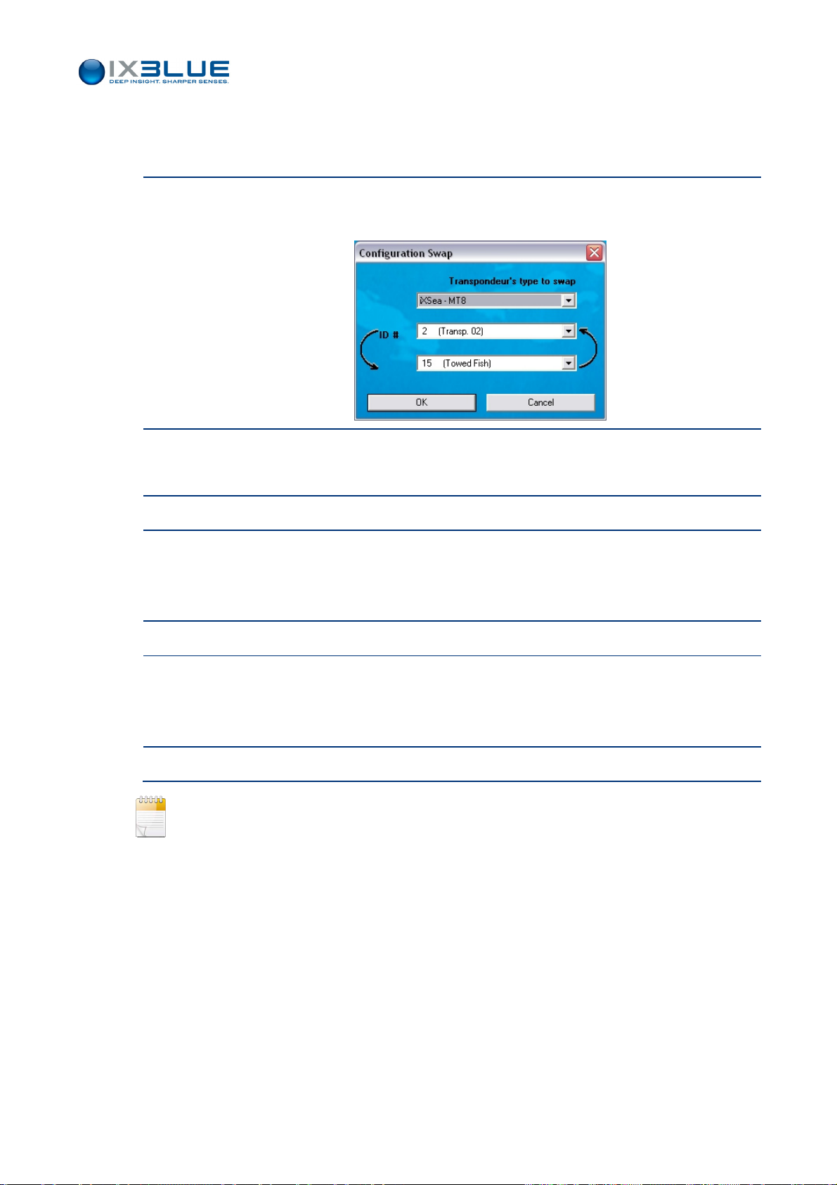
GAPS – User Guide
Swapping
Step Action
1.
2.
3.
To exchange the characteristics of two transponders: their IDs remain unchanged but all
their characteristics are exchanged.
Select Swap… option of the Transponders menu.
The Configuration Swap window appears:
Select the two ID transponders you want to exchange and click OK.
The transponder IDs turn red in the transponder list.
Edit one of the swapped transponders.
4.
Click Valid button to validate the modifications if GAPS is not operating otherwise stop
GAPS before clicking the Valid button.
The transponder ID in the transponders list (near the Transponders menu) turns black.
5.
Edit the other swapped transponder.
6.
Click Valid button to validate the modifications if GAPS is not operating otherwise stop
GAPS before clicking the Valid button.
The transponder ID in the transponders list (near the Transponders menu) turns black.
7.
End of procedure.
Only the not ‘In Use’ transponders can be swapped.
Do not forget to check ‘In Use’ check box if necessary after swapping.
MU-GAPS-AN-003 Ed. L – May 2012
63
Page 76
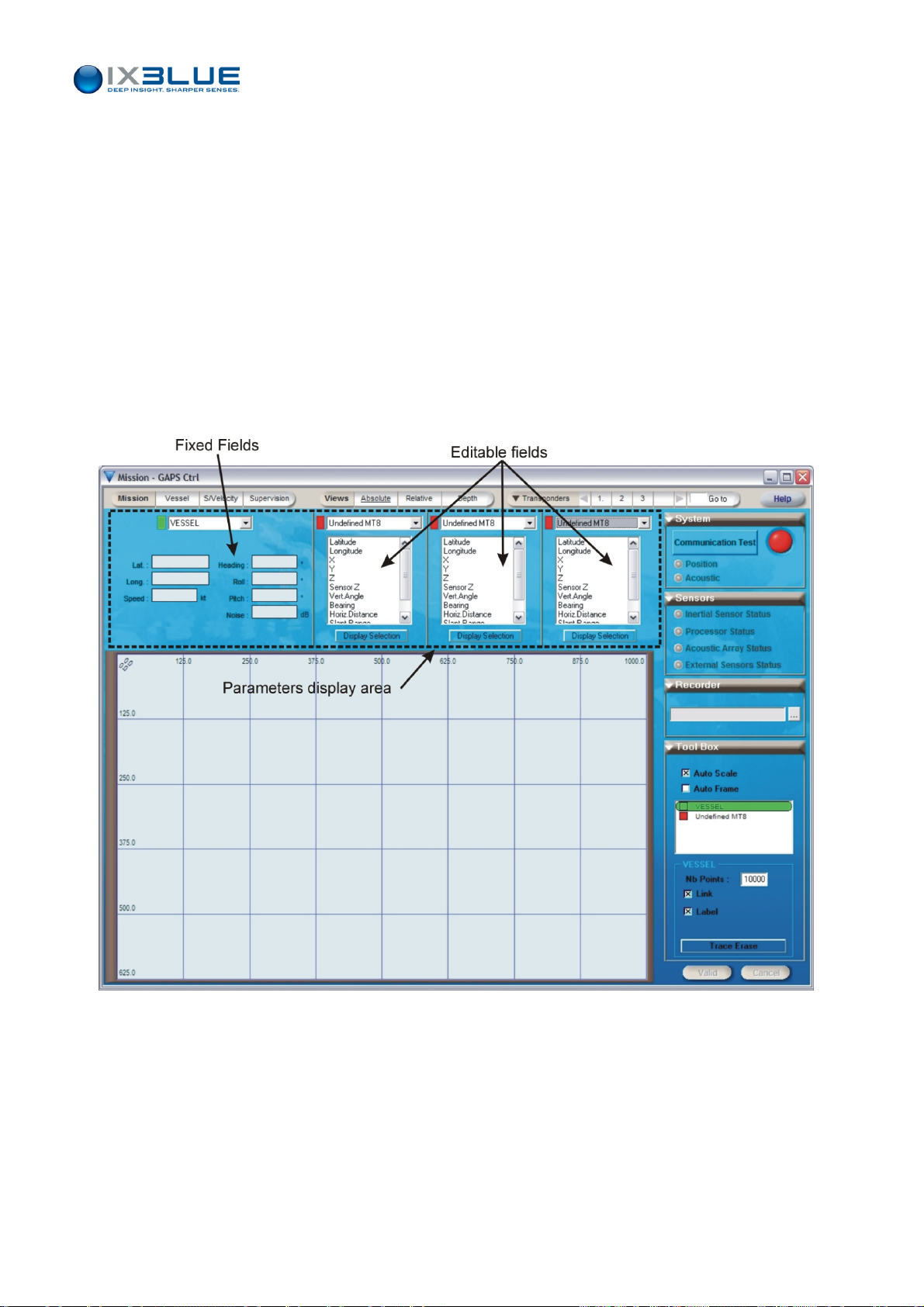
III.4 Monitoring the GAPS in Operation
III.4.1 CONTROLLING THE REAL TIME DATA
To control the real time data, the MMI software offers three kinds of view:
• The absolute view: it is a geographic mode, in which you can see all the mobiles
evolving together
• The relative view: it is fixed on the ship. You can visualize the motion of the mobiles
relative to the ship
• The depth view: it shows the mobile depths relative to time
All these three views have a common area: the Parameter Display area located top of the
Display area (see Figure 43).
GAPS – User Guide
Figure 43 - P
In this Parameter Display area, you can select
• From the upper left part: a mobile (vessel or transponder), the displayed fields are
fixed and depend on your mobile choice.
• From the upper middle part:
The mobiles of which you want to visualize the parameters,
The parameters to visualize for each mobile.
arameter Display Area (Absolute view case)
MU-GAPS-AN-003 Ed. L – May 2012
64
Page 77
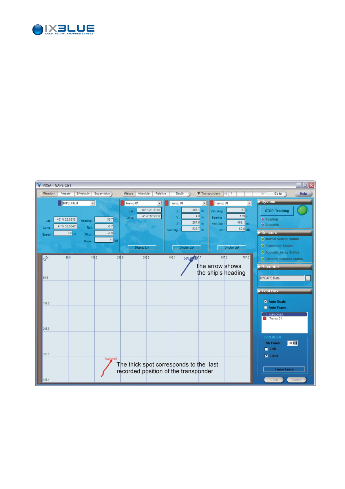
Once selected, you can visualize them by clicking on Display Selection button below.
The parameters of four mobiles including the vessel can be visualized at the same time.
You can select and display the following parameters:
For the vessel: latitude, longitude, speed, heading, roll, pitch, noise
For the transponders: latitude, longitude, X, Y, Z, pressure sensor, Vertical
Angle, Bearing, Horizontal Distance, Slant Range, Signal To Noise Ratio.
For all views, you can visualize the parameters of up to four transponders simultaneously
including the vessel.
III.4.2 VISUALIZING WITH THE ABSOLUTE VIEW
GAPS – User Guide
Window
Access
Window
To display the real time data in a geographic display, select Absolute tab under the
Views menu.
The corresponding window (see Figure 44) appears.
Figure 44 - A
bsolute view
MU-GAPS-AN-003 Ed. L – May 2012
65
Page 78

GAPS – User Guide
The Tool Box contains the following parameters:
• Auto Scale, (full extent, grid limits are set in order to view all data in graph) applied to
selected mobile in the bow below.
• Auto Frame, (when the selected mobile crosses the grid limits these limits are
updated) applied to the selected mobile in the bow below:
Check this box: a cross-mark appears in the Vessel box
Then click on the box of the selected mobile (for example, in the of the fish
mobile in the Figure 44): the cross-mark is now displayed in the box of the
selected mobile.
•
The mobile you want to set the focus on. All the graphical settings will be applied
relatively to this selected mobile. By default the vessel is selected.
• Number of displayed points
• Link (draw a line between all the points of the mobile)
• Label (add the name of the mobile in the map) close to the last position received
The grid can be either in geographical coordinates (latitude, longitude) or in metric
ones. To switch between the units, press the shortcut keys: [Alt ]+ mouse Left Click. The
metric display has its origin in the upper left corner of the graph.
You can zoom in the graph with a left click and zoom out with a right click.
You can move the center of the graph by holding down [shift] key + left click.
You can erase all points of the selected mobile with the Trace Erase button.
A bigger spot than all the others symbolizes the last position of the displayed point. It
represents the last known position of the mobile. The arrow, which represents the ship, is
oriented following the current ship heading (see Figure 44).
MU-GAPS-AN-003 Ed. L – May 2012
66
Page 79
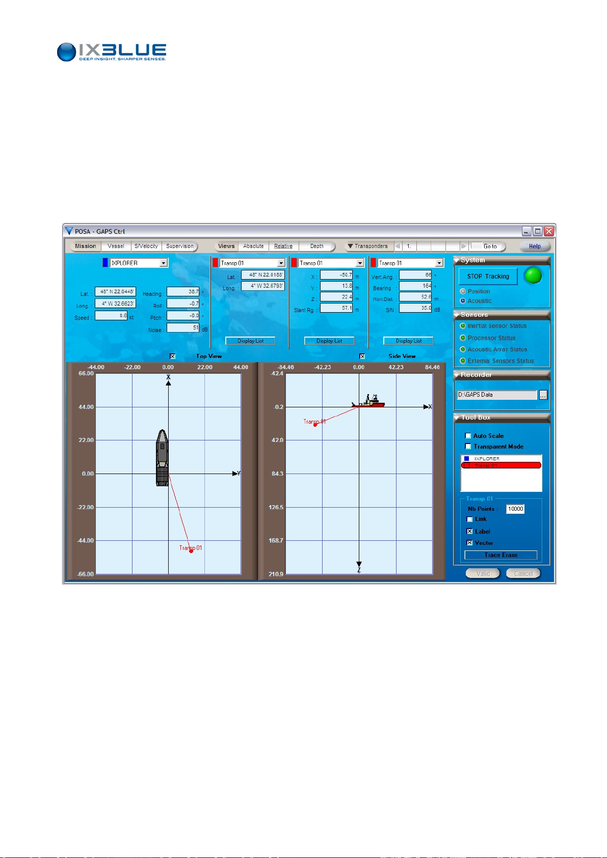
III.4.3 VISUALIZING WITH THE RELATIVE VIEW
GAPS – User Guide
Window
Access
Window
Description
In the relative view, you can see the trajectory of the mobile relative to the ship. The view
is centered on the vessel. To display the real time data in a relative display, select
Relative tab under Views menu.
The corresponding window appears. The Figure 45 displays the relative view with a GAPS
d at 6 m from the stern and at 2 m from the port side (inside the ship): Xp = -6 m
locate
and Yp = -2 m in this case.
Figure 45 - Relative view
All the graphical settings are the same than in the absolute view except that you have:
• A transparent mode that allows you to see data taken under or behind the ship (case
of a diver swimming under the ship).
• A vector that can be drawn (it draws a line between the last point and the vessel).
You can also choose to see only the Side View or the Top View by clicking the check
boxes on top of both views.
With the Auto Scale option checked, the full extent is made on the data, the ship
disappears, the origin or GAPS remains on the display.
MU-GAPS-AN-003 Ed. L – May 2012
67
Page 80
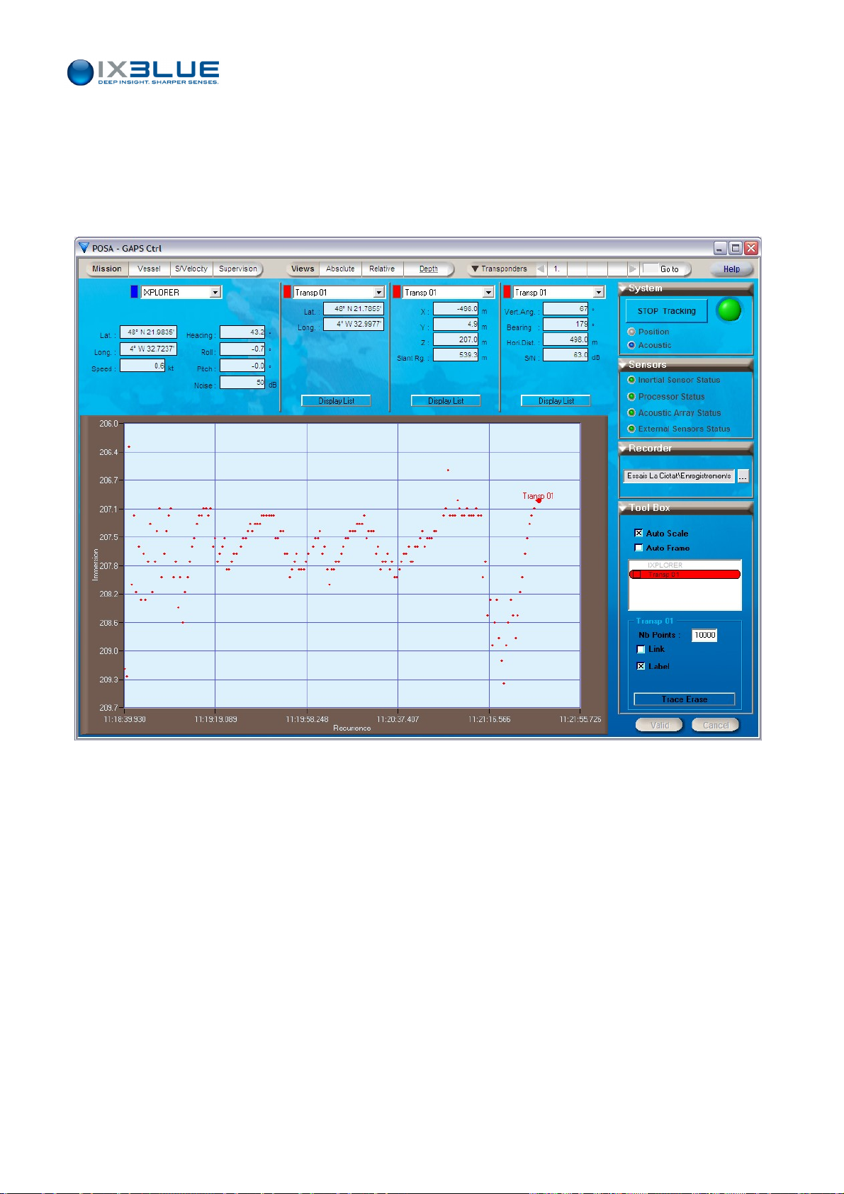
III.4.4 VISUALIZING WITH THE DEPTH VIEW
GAPS – User Guide
Access
Window
The depth window displays the mobile depth.
To display the real time data in a depth view, select Depth tab under Views menu.
The corresponding window (see Figure 46) appears.
Figure 46 - D
epth view
The graphical settings are the same than in the absolute view.
• Auto Scale: on the immersion, maximum extent of all points
• Auto Frame: on the immersion, maximum extent of the points of the selected
mobile(s)
• Nb Points: as long as the entered number of displayed points is not reached, the
display is compressed. When this maximum number is reached, the display shifts
along the left of the time scale
MU-GAPS-AN-003 Ed. L – May 2012
68
Page 81
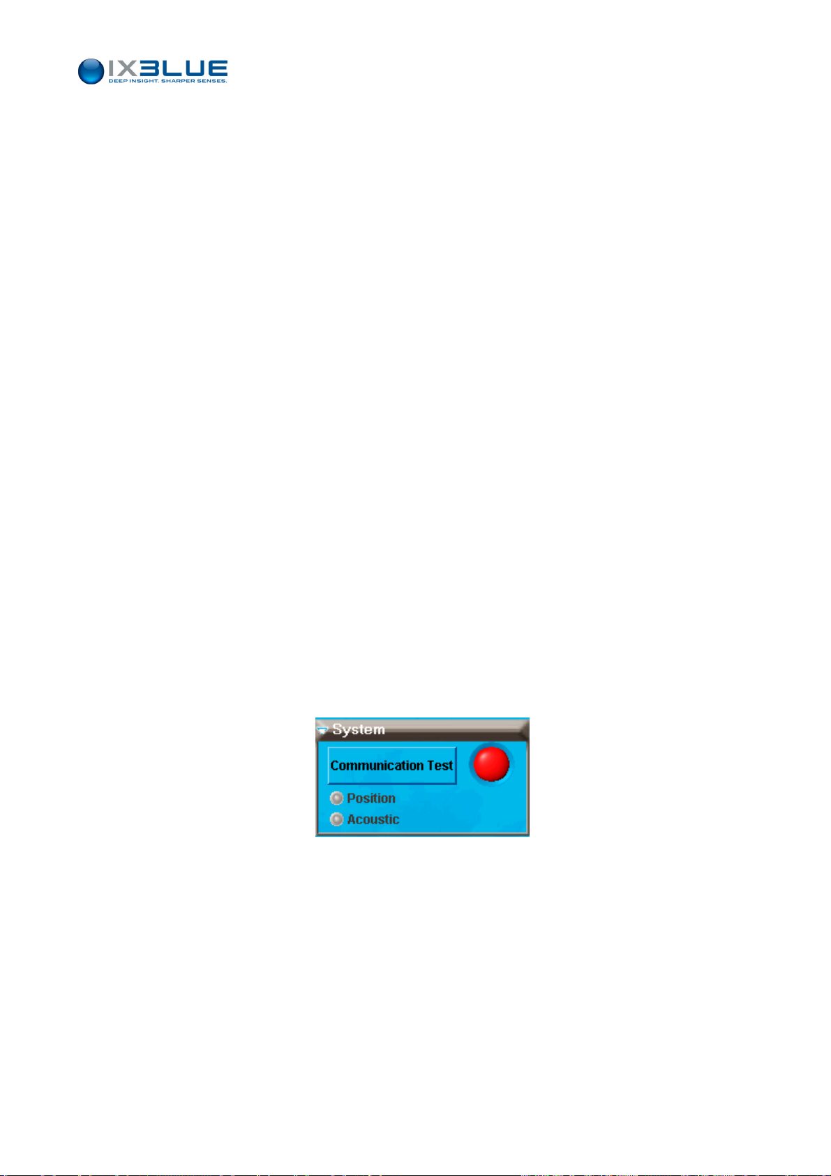
III.4.5 CONTROLLING THE GAPS STATUS
The System and Sensors boxes are designed to help you to monitor the GAPS status.
GAPS – User Guide
System Box
The System box is composed of (see Figure 47):
•
A communication button. Changing a functional parameter anywhere in the software
while a GAPS is tracking and validating it will make this button flash with a red frame.
This means that the changed parameter is not applied to the GAPS and that if you
want to apply it you will need to stop the system
This button is labeled as follows:
“Communication Test” if GAPS is not connected,
“STOP Tracking” if GAPS is connected and active. Clicking this button stops
the acoustic part of GAPS, no emission and reception is performed anymore.
Inertial and GPS activities (attitude and GAPS/vessel position) are still ON.
“START tracking” when GAPS is connected but not active.
• A system status light:
Red when GAPS not connected to the PC (or when it is stopping or starting
the tracking)
Blue if GAPS is not active
Green when GAPS connected and active
• Two status and command buttons for Position and Acoustic ping outputs. These
Sensors box
status buttons flash in blue/mauve each time an acoustic ping is transmitted or
position signal is received. This effect gives an idea of the actual recurrences of the
position and acoustic ping transmitted. Clicking on the associated buttons brings you
to the Supervision window with a specific tool box allowing the set-up of acoustic and
position parameters.
Figure 47 - System box
Four status and buttons are available (see Figure 48). Each of these buttons opens
cific tool box. The color button follows a code giving the status of the sensor.
spe
The color code for the four status lights is the following:
• Red for Alarm
• Orange for Warning
• Green for Normal
MU-GAPS-AN-003 Ed. L – May 2012
69
Page 82
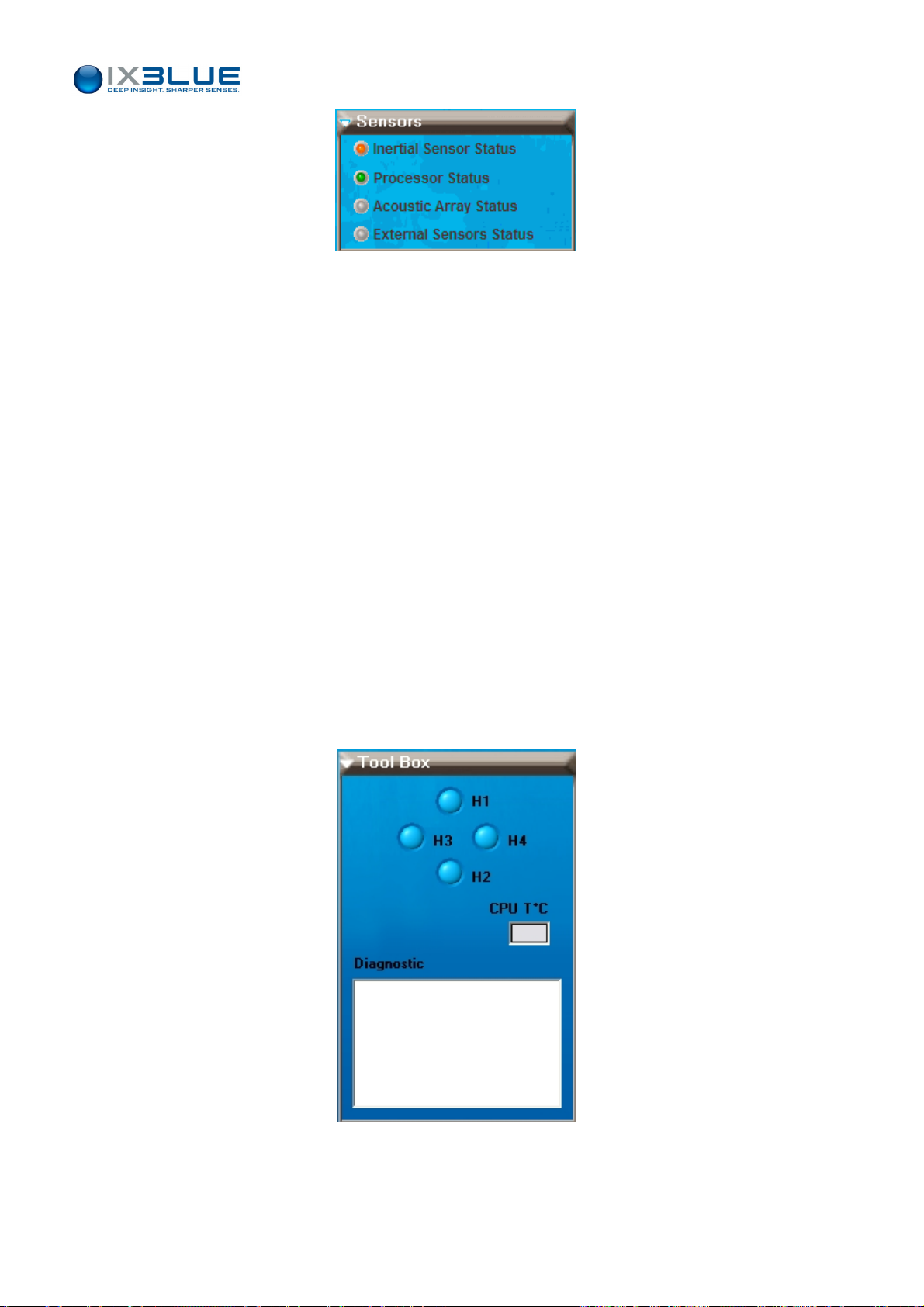
GAPS – User Guide
Figure 48 - Sensors Box
In the associated tool box, you can see the operating state of the device:
• Inertial Sensor Status Tool Box: it contains status lights and a diagnostic zone
displaying alarm or warning messages (see Part V).
• Processor Status Tool Box: it contains a diagnostic zone displaying alarm or warning
messages (see Part V).
• Acoustic Array Status Tool Box: it shows the status of the four hydrophones (see
Figure 49). A red status means that the hydrop
hone did not receive an expected
signal. If one of the hydro status stays red during several interrogations the
hydrophone might be damaged (contact iXBlue for support and assistance). The CPU
temperature is the temperature of the electronics contained in GAPS. It is the
temperature of the warmer electronic component (CPU).
• If the rectangle light is orange: the temperature is high (> 70°C). This situation must
be kept under very close control. For example check if the GAPS antenna is not out of
water.
• If the rectangle is red: the temperature is very high (> 75°C). You must switch off the
GAPS and contact iXBlue support.
Figure 49 - Acoustic Array Tool Box
MU-GAPS-AN-003 Ed. L – May 2012
70
Page 83
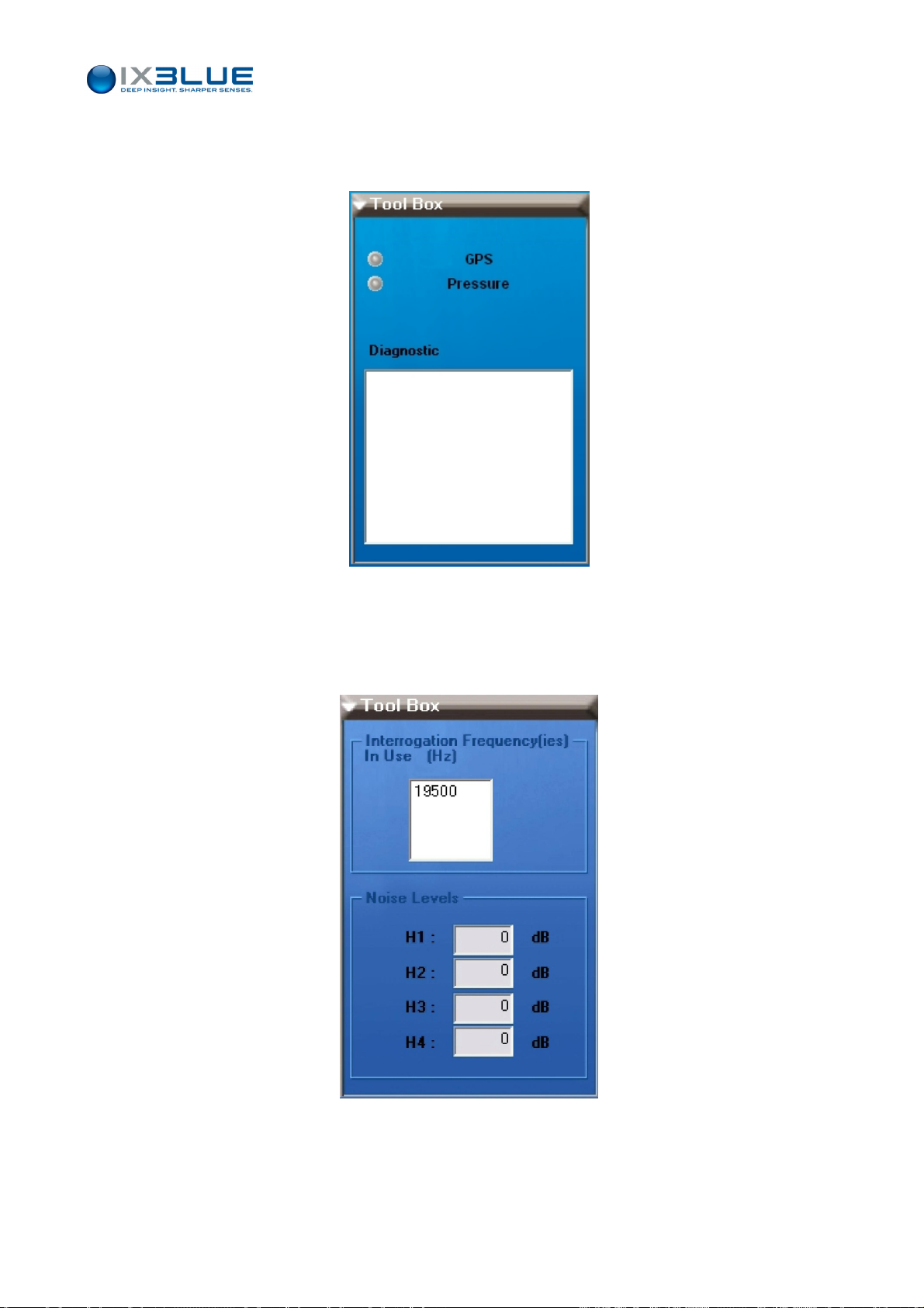
GAPS – User Guide
• External Sensor Status Tool Box : it allows a quick check on the status of GPS and
optional pressure sensor (see Figure 50). It also contains a diagnostic zone displaying
alarm o
r warning messages.
Figure 50 – Tool box of the External Sensors Status
Ambient
Noise
The sea ambient noise is measured at the hydrophones faces and displayed in the tool
box in the Supervision menu after clicking on the acoustic antenna:
Figure 51 – Tool box displaying the noise level for all the hydrophones
MU-GAPS-AN-003 Ed. L – May 2012
71
Page 84
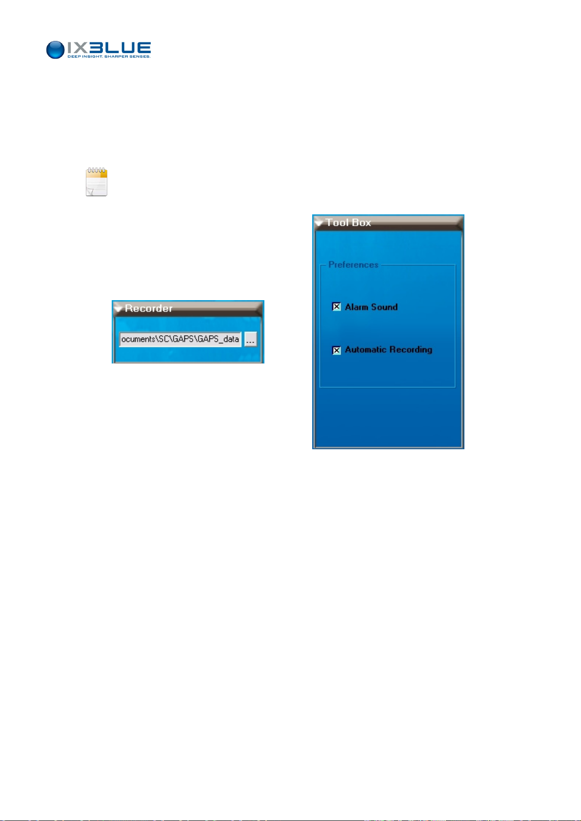
III.5 Recording the Data
A recorder box allows data recording in a file in real time. This recording is automatic
when the check box Automatic Recording is checked (see Figure 52). This check button
e found in the Supervision menu in the toolbox of the MMI parameters button.
can b
The automatic file name format of the file is “YearMonthHourMinuteSecond.dat”.
Each time the data file size reaches 1 Mo a new data file is created.
The whole software configuration is always saved in the first data file.
GAPS – User Guide
Figure 52 - Recorder box – Automatic recording check box
MU-GAPS-AN-003 Ed. L – May 2012
72
Page 85

IV OPERATING GAPS
Before starting any operation, you should know what to expect in terms of performances,
GAPS – User Guide
range and accuracy (see section IV.1). Every operation starts by the co
system and its initialization (see section IV.2). During the survey, you ca
operation (see section IV.3).
IV.1 Performances
In complex marine environments, GAPS offers different levels of performances. See
below the global GAPS performances depending on the GPS operating modes (section
IV.2.1) and the variation graphs of the range and the a
and SNR.
IV.1.1 POSITION ACCURACY FOR MT8, MT9 AND ET8 TRANSPONDERS
Characteristics Typical Values
Positioning accuracy
for MT8, MT9, ET8
transponder
• Accuracy: from 0.2 to 0.7%
depending on noise level
• Range: 4,000 m
Deep water Shallow water
ccuracy versus depth, noise level
• Accuracy: around 1%
• Range: > 1,000 m (2 to 4 times
more depending on the weather)
nfiguration of the
n control the
Positioning accuracy
for ORE transponder
GPS Position
accuracy
Position drift
(during GPS drop out)
• Rejected Erroneous Positions:
from 0 to 0.3%
Deep water Shallow water
• Accuracy: around 3 %
depending on noise level
• Range: 1,000 m
Rejected Erroneous Positions:
around 50 % vertically and
propellers stopped
2 to 5 cm (external RTK receiver)
0.5 to 3 m (integrated DGPS or internal or external)
5 to 15 m (GPS receiver)
2 m / 2 minutes
• Rejected Erroneous Positions:
from 0 to 0.3%
• Accuracy: around 2 to 5 %
depending on angle
• Range: a few hundred meters
Rejected Erroneous Positions: from
30 to 90 % depending of the angle
from 0° to 60° from vertical
MU-GAPS-AN-003 Ed. L – May 2012
73
Page 86
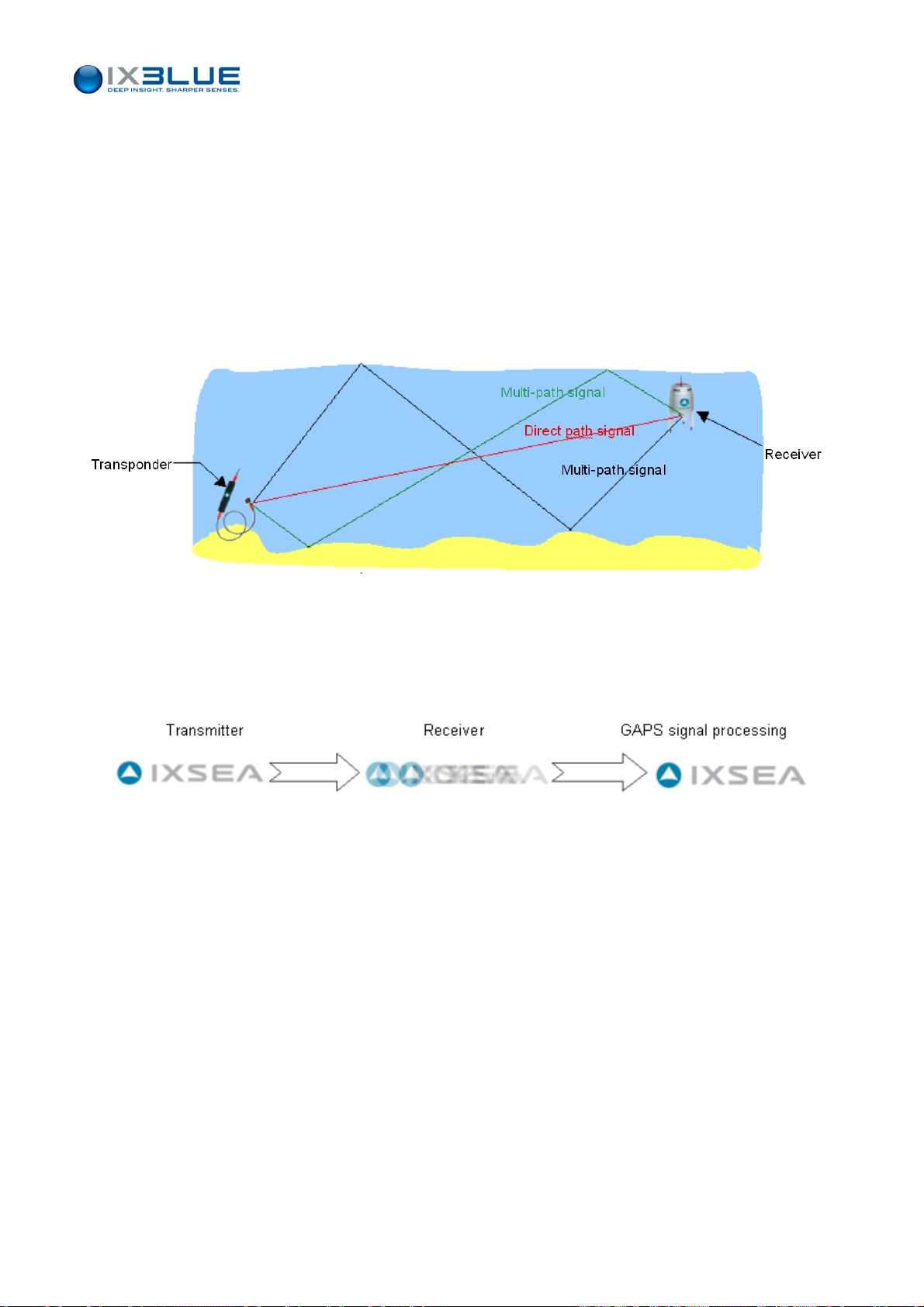
IV.1.2 MULTI PATH
The multi-path phenomenon is usually a major issue for standard USBL systems. GAPS
uses wide-band spectrum signals and is fitted with a powerful signal processing that
reduces a lot the result of the multi-path signals.
Nevertheless this phenomenon may happen from time to time and lead to noisy positions
under specific conditions (specific distances between the transponder and/or the GAPS
antenna and a reflective surface).
• Multi-path
GAPS – User Guide
Figure 53 – Multi-path Phenomenon
The transponder transmits one signal. The GAPS antenna receives this signal plus
additional echoes mixed together.
• Analogy with images
MU-GAPS-AN-003 Ed. L – May 2012
74
Page 87
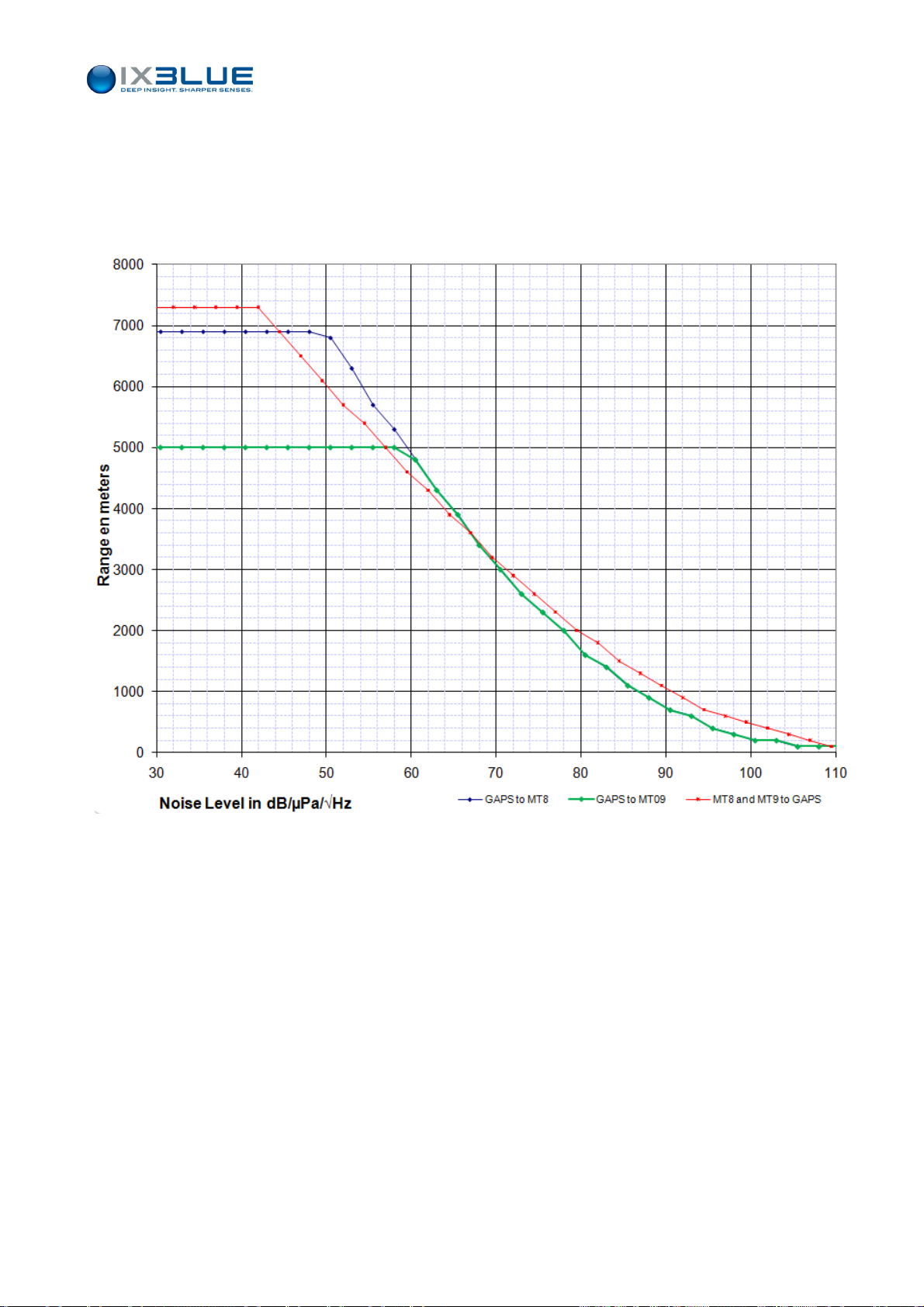
GAPS – User Guide
IV.1.3 R
ANGE VERSUS NOISE LEVEL
The GAPS performances are on the Figure 54 with
• GAPS Signal Level of 191 dB
• Transponder Signal Level = 188 dB
Figure 54 – GAPS Performances in Range versus Noise Level
MU-GAPS-AN-003 Ed. L – May 2012
75
Page 88
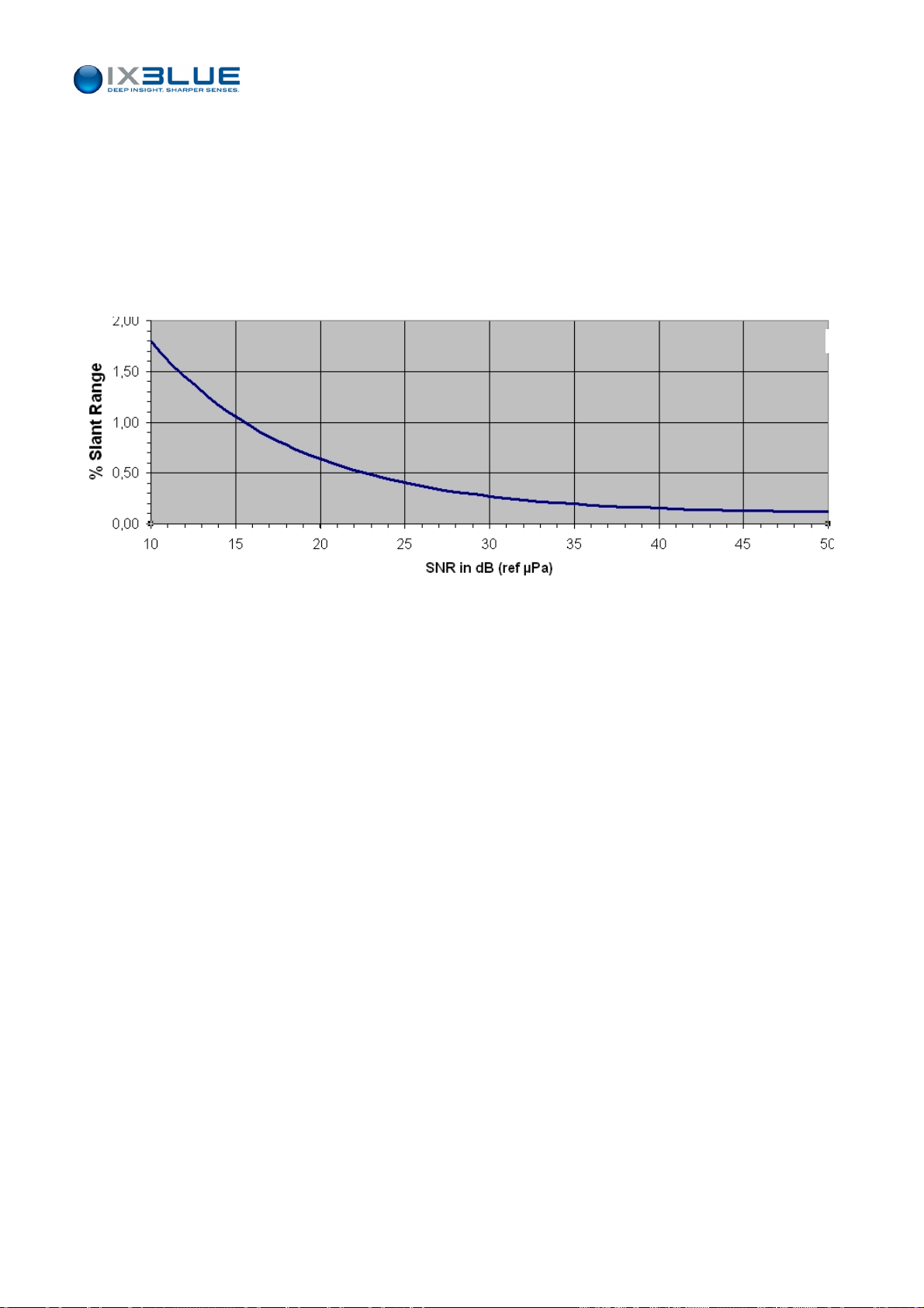
IV.1.4 ACCURACY VERSUS SNR
The GAPS performances are described on the Figure 55 with:
• Slant Distance ≥ 1,000 m
• Vertical Angle < 30 deg
• Roll & Pitch Error = 0.01 deg
• Heading Error = 0.1 deg
• GPS error ≤ 1.5 m
GAPS – User Guide
Figure 55 – GAPS Performances in Accuracy versus SNR (SNR at GAPS processing output)
MU-GAPS-AN-003 Ed. L – May 2012
76
Page 89
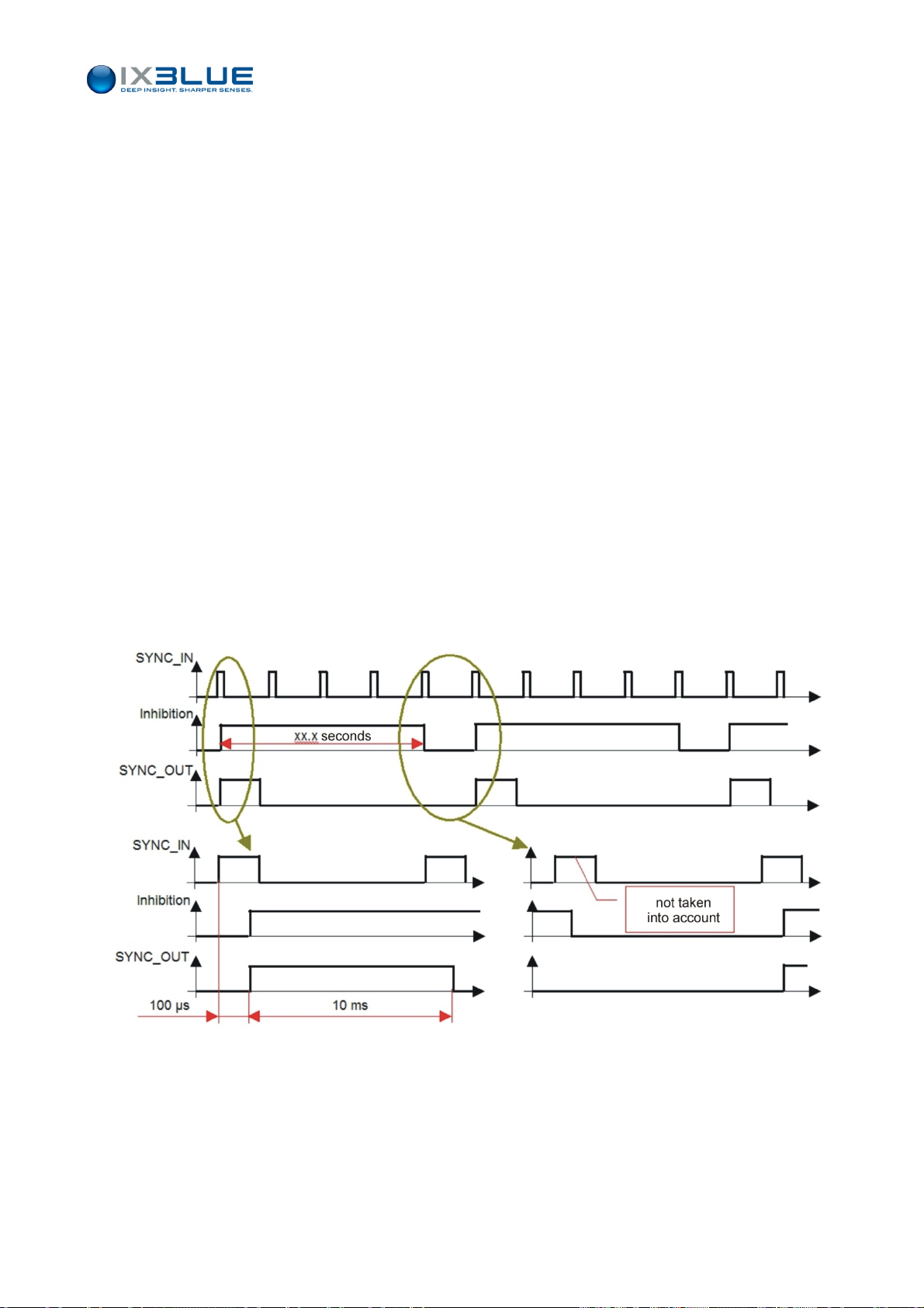
IV.2 Initializing and Configuring a Survey
You need to choose the mode in which GAPS is going to operate (section IV.2.1) before
initializing the system (section IV.2.2). The choice of the operating mode constrains the
uration (section IV.2.3).
config
IV.2.1 OPERATING MODES
IV.2.1.1 Synchronization Mode / Recurrence
The system can be synchronized by and with another system or can generate itself its
acoustic recurrences:
• Internal recurrence: the interrogation time for the transponder is automatically
determined by GAPS. The Internal recurrence is fixed: it is configured to a fixed value
with the MMI.
GAPS – User Guide
• External Synchronization: an external system generates a synchronization to
operate GAPS.
• External Synchronization with inhibition: the GAPS minimum recurrence inhibits
the short external recurrence after one received trigger. GAPS is triggered on the
rising edge of the signal. This mode is described on the Figure 56.
Figure 56 – Inhibi
tion window during an external synchronization
MU-GAPS-AN-003 Ed. L – May 2012
77
Page 90
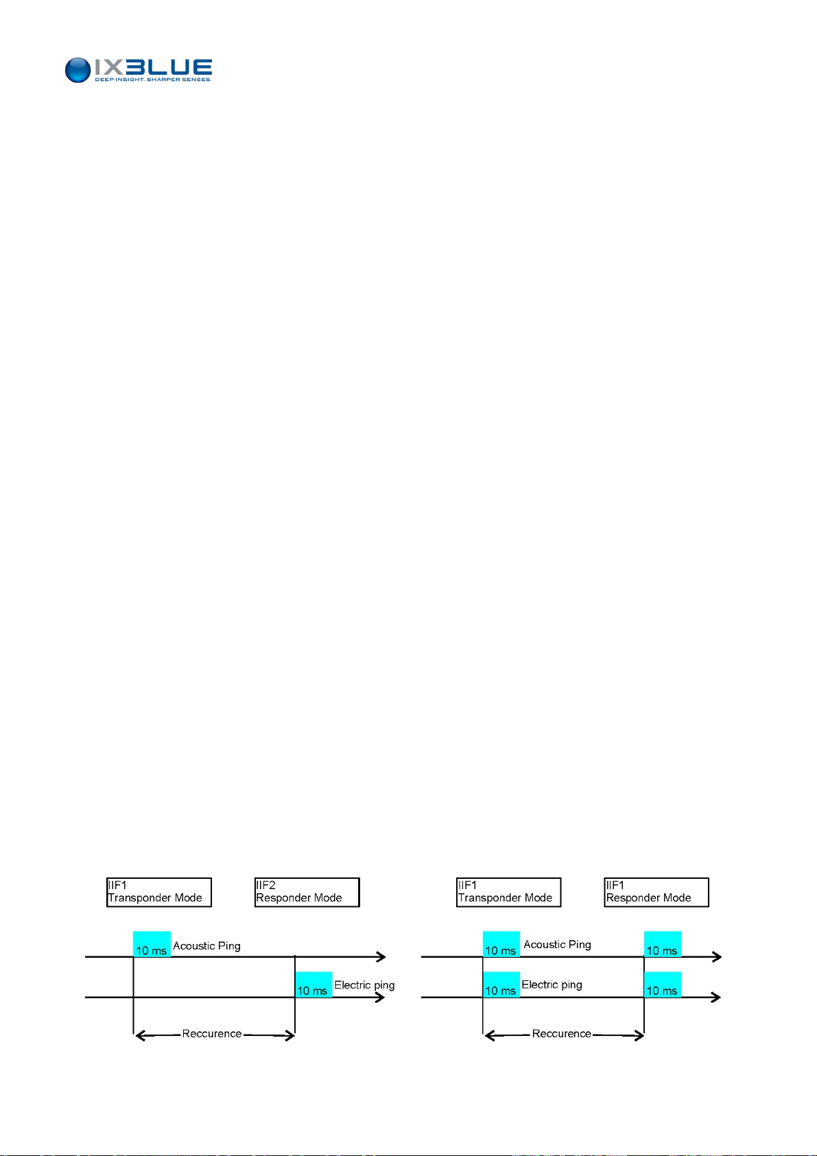
IV.2.1.2 Two Modes
The GAPS interrogates acoustically (transponder mode) or electrically (responder mode).
• Transponder mode: GAPS acoustically interrogates the transponder that replies with
a MFSK signal. The time between signal interrogation and reception is approximately
1 second every 750 m transponder range with a velocity of 1500 m/s.
• Responder mode: the transponder is electrically triggered through the SYNCHRO
OUT- RESPONDER MODE output and GAPS does not send acoustic signal anymore.
This mode has many advantages:
GAPS – User Guide
The position update is twice faster in responder mode than in transponder
mode because there is only one acoustic travel in this mode. The first travel is
electric. There are two acoustic travels in transponder mode.
The transponder cannot be accidentally triggered by any parasitic sound.
The transponder is always triggered despite noise (e.g. ROV propellers).
Depending on the environmental conditions, the maximum range of the system
is sometimes limited by the reception of the acoustic triggering signal by the
transponder. This is no more limitation in responder mode and the maximum
range is only limited by the reception of the reply by the GAPS acoustic array.
The drawback is that the electrical signal has to be transmitted up to the transponder
usually through an electrical or a fiber optic wire or by using synchronous clocks (GAPS in
external synchronization mode).
IV.2.1.3 Multi Transponders Mode
Several Acoustic Transponders can be interrogated simultaneously. The transponders are
separated thanks to the two MFSK codes (22, 23) and the four Individual Interrogation
Frequencies (IIF). Thus, up to 8 (4 x 2) transponders can be positioned.
You can also use seven beacons in transponder mode (by using the four different
Individual Frequencies available and the two codes 22 and 23) and one beacon in
responder mode in the same configuration.
If you want to use two transponders, the first one in transponder mode, the second one in
responder mode, and if you want to interrogate them simultaneously (i.e., in the same
recurrence), both transponders must be configured with the same IIF. When they are
configured with two different IIF, they will be interrogated alternatively every second
recurrence. See Figure 57.
Figure 57 -
Two Transponders in Transponder and Responder modes
MU-GAPS-AN-003 Ed. L – May 2012
78
Page 91
GAPS – User Guide
When a transponder is configured in transponder mode, no signal is generated on the
SYNC OUT output of the ECB (responder mode).
HEN THE TWO INTERROGATION FREQUENCIES ARE DIFFERENT, THE BLANKING TIME IS HIGHER
W
THAN THE ACOUSTIC RECURRENCE. IN A SINGLE TRANSPONDER MODE, YOU CANNOT HAVE A
IV.2.2 I
Procedure
BLANKING TIME HIGHER THAN THE ACOUSTIC RECURRENCE
BLANKING TIME HIGHER THAN THE RECURRENCE
TWO DIFFERENT FREQUENCIES
TRANSPONDER HARDWARE AND LET A BLANKING TIME LOWER THAN THE RECURRENCE IN THE
MMI. O
NITIALIZING
I
WAIT AT LEAST 20 S BEFORE TURNING IT ON AGAIN
DO NOT
NLY THE BLANKING TIME SET IN THE HARDWARE IS TAKEN INTO ACCOUNT
GAPS
F YOU TURN OFF
TRANSMIT ACOUSTICALLY WITH
Step Action
1.
Turn the ECB switch to ON.
2.
On the ECB, turn GAPS switch to ON.
GAPS
BY PRESSING THE
. I
N THE
MMI
YOU CANNOT SET UP A
. S
O WHEN YOU USE TWO TRANSPONDERS WITH
,
MAKE SURE TO HAVE THE CORRECT SETTINGS IN THE
.
GAPS
POWER SWITCH ON THE
ECB,
MAKE SURE TO
.
GAPS
IN THE AIR
.
GAPS is running its initialization tests. Wait for about 30 s.
3.
Launch the MMI software on your PC.
MMI scans all the ports of the PC. After completing this communication test successfully,
the command button on the upper right corner of the MMI window becomes a “Start
tracking” button.
4.
Press START tracking button in the MMI.
This action starts the acoustic cycle of GAPS. The INS needs 5 minutes before being
operational.
5.
Check for end of the alignment inertial sensor alarm message on the MMI software: in
the sensor box, check the Inertial Sensor status light: orange during the “coarse
alignment”, green during the “fine alignment” (typically 30 minutes but could be longer).
6.
Check for available Data control views in MMI (absolute, relative, depth).
7.
End of procedure.
MU-GAPS-AN-003 Ed. L – May 2012
79
Page 92

INS
Initialization
GAPS – User Guide
• During the first five minutes after powering-on, the inertial system performs its coarse
alignment:
Inertial sensor data (accelerometers and gyrometers) are computed to
estimate heading, roll and pitch angles.
At sea, it is recommended that the system is kept as steady as possible during
coarse alignment: oscillations around a mean position or smooth drift are
permitted but accelerations should be avoided. Leaving the vessel adrift for 5
minutes would lead to satisfactory conditions for coarse alignment.
No estimation of position or speed, nor errors, are done by the INS during the
coarse alignment: the data provided by external sensors (lever arm
compensated) are used directly.
• After the coarse alignment phase, the GAPS is ready for navigation. Kalman filter is
activated to compute and estimate position and speed with an optimal accuracy. The
INS switches to the “fine alignment” phase to improve the accuracy of roll, pitch and
heading estimations.
During the fine alignment phase, movements of the vessel are required. 90
degrees rotations are even recommended so that the Kalman filter assesses
the sensors bias on different axes.
Error estimations from the INS Kalman filter are improved when optimal
trajectories are performed. The optimal trajectory to achieve fast fine alignment
is “staircase” shaped, as illustrated in Figure 58, with a typical duration of 3 to
5 minutes fo
r each step. Such a trajectory allows the Kalman filter to assess all
sources of errors of the system, to correct them and to achieve optimal
performances at the end of the fine alignment process.
When a “staircase” shaped trajectory is performed, the fine alignment phase
would typically last for less than 20 min.
The fine alignment requires the GPS to provide valid data to the system. the
INS uses both inertial sensors and external sensors to compute optimal
estimates of position, speed, attitude and heading.
The fine alignment is ended automatically when the heading covariance is
below 0.1 degree.
MU-GAPS-AN-003 Ed. L – May 2012
80
Page 93

GAPS – User Guide
Starting point
Arrival point
Figure 58 - Illustration of optimal trajectory for fine alignment
The inertial sensor status light turns green at the end of the coarse alignment. You can
then start to operate with GAPS. The accuracy of the INS is optimal at the end of the fine
alignment. At the end of the fine alignment, the message “fine alignment” disappears from
the inertial sensor tool box.
MU-GAPS-AN-003 Ed. L – May 2012
81
Page 94

GAPS – User Guide
IV.2.3 C
Configuring MMI general parameters on a User PC
GPS Lever
ONFIGURING THE MISSION PARAMETERS
For more details on these procedures, please refer to section III.3.
Step Action
1.
Under the Mission menu, select the Vessel tab, enter the ship dimensions.
2.
Under the Mission menu, select the S/Velocity tab, enter the velocity profile.
3.
Under the Mission menu, select the Supervision tab, enter the interface parameters:
• In the Serial Link tool box, choose GAPS Regular for the Position protocol and
set-up the serial parameters
• In the Output toolbox, choose the output position protocol if needed
4.
End of procedure.
In the MMI software, the GPS lever arms, if they exist, have to be entered.
Arms
About the GPS antenna, two main configuration cases exist:
• The GPS antenna is vertically above GAPS
• The GPS antenna is NOT above GAPS
Configuring the GPS lever arms when the GPS is vertically above GAPS
Step Action
1.
Under the Mission menu, select the Vessel tab, set the GPS X, Y lever arms to zero.
2.
Enter the Z lever arm.
• If GAPS is mounted on a pole, GAPS should be placed in a way that the
hydrophone H1 is oriented towards the bow of the ship.
• If a rigid rope holds GAPS, you always have a slight error induced by the motion
of the rope, even if the GPS antenna is put vertically above GAPS.
3.
End of procedure.
Configuring the GPS lever arms when the GPS is NOT vertically above GAPS
Step Action
1.
Under the Mission menu, with the Vessel tab selected, set the position offsets X, Y, Z of
the GPS antenna with respect to GAPS.
2.
End of procedure.
GPS lever arms must be entered in the GAPS reference frame.
MU-GAPS-AN-003 Ed. L – May 2012
82
Page 95

GAPS – User Guide
IV.2.4 I
Procedure
NSTALLING THE TRANSPONDERS
Step Action
1.
In the MMI software, under the Transponders menu, add the transponder to your
system and set up its configuration (see Part III.3.10 of this manual).
2.
In the associated toolbox, check In Use box to make it operational and set the
associated parameters up (at least IIF, MFSK code, transponder/responder mode, turn
around time, filter).
3.
In case of a transponder with a remote transducer, connect the remote transducer to the
transponder body.
4.
Plug the transponder for power supply to the vehicle carrying it.
This connection is used in both transponder (only power supply) and responder mode
(power supply and triggering coming from GAPS).
5.
In responder mode, connect the vehicle to the “Synchro Out” BNC plug on the ECB or to
your SOURIAU socket if you do use the ECB. For transponders triggered by a TTL
signal, plug the responder cable on the rear face of the ECB. For the transponders
triggered by a differential signal, plug the responder cable on the front face of the ECB.
6.
End of procedure.
I
MPORTANT FOR
D
O NOT FORGET TO SELECT
THE RECEPTION CHANNEL FREQUENCY YOU WANT TO USE BY SELECTING IT WITH THE SWITCH
-
LOCATED ON THE BOTTOM END PLATE OF THE TRANSPONDER
THE CODE, TURN AROUND TIME AND BLANKING TIME BY THE MEAN OF SWITCHES LOCATED
-
INSIDE THE TRANSPONDER
CTUAL TRANSPONDER SETTINGS HAVE TO MATCH THOSE INTRODUCED INTO THE
A
MT8
AND
ET8 T
:
RANSPONDERS
GAPS MMI
MU-GAPS-AN-003 Ed. L – May 2012
83
Page 96
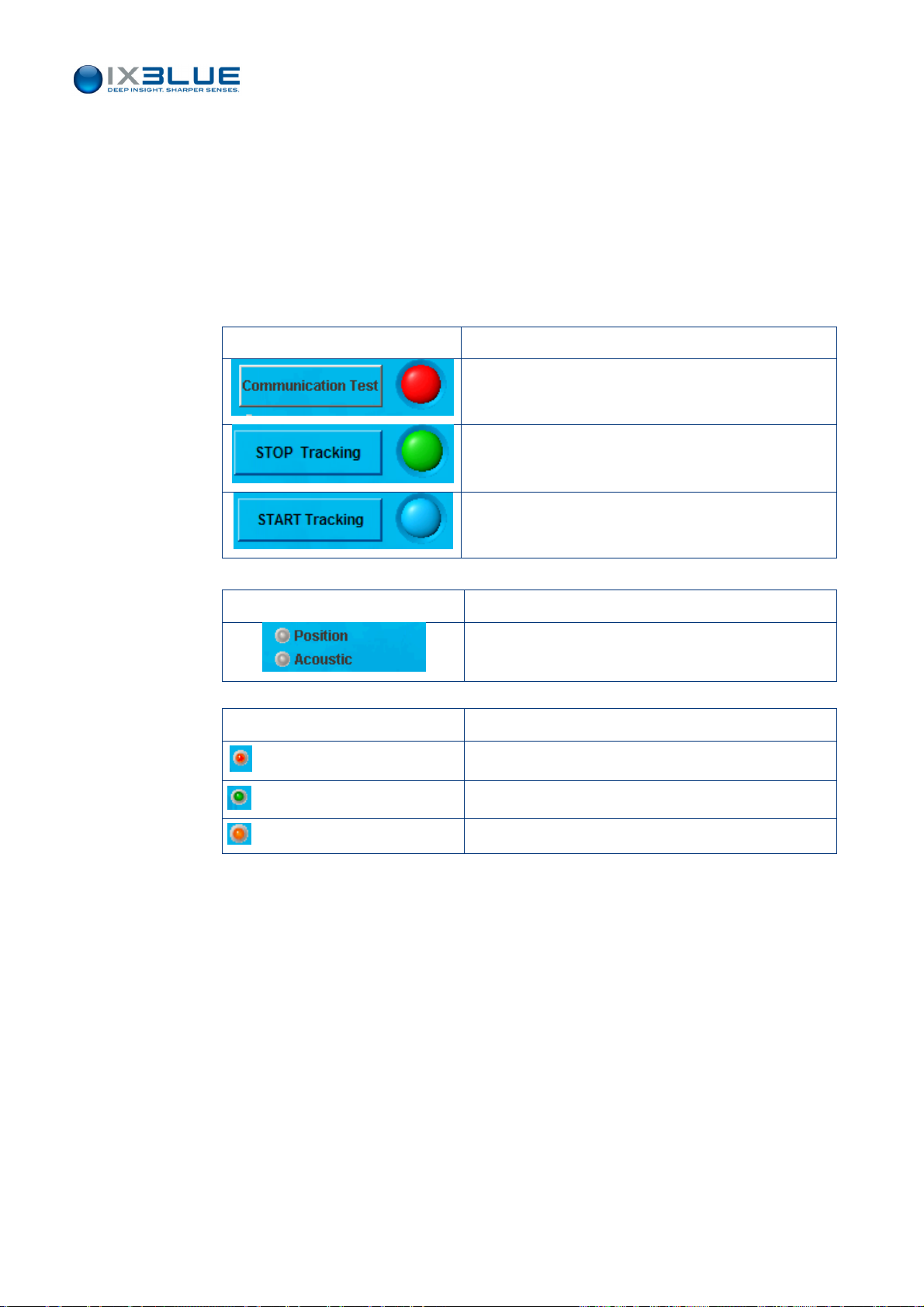
IV.3 Monitoring the Survey
IV.3.1 VISUALIZING THE TRAJECTORY
Refer to section III.4 for a complete description of the control windows in the MMI
software.
IV.3.2 LIST OF THE SYSTEM STATUS
GAPS – User Guide
System Box
Sensor Box
Button/ status light Meaning
GAPS is not connected
GAPS is connected and active. GAPS is pinging.
GAPS is connected, not acoustically active (but it
gives the ship position).
Position and Acoustic lights Meaning
Flashing in blue/mauve each time a position is
computed and an acoustic ping is sent.
Status light Meaning
Red light in case of an alarm
Menu Text
Label
When you modify some parameters in the different windows or tool boxes, the
corresponding menu titles are set to red. This color code means that modifications have
been made but not applied yet in the MMI and/or GAPS itself.
Green light for a normal status
Orange light in case of a warning
MU-GAPS-AN-003 Ed. L – May 2012
84
Page 97
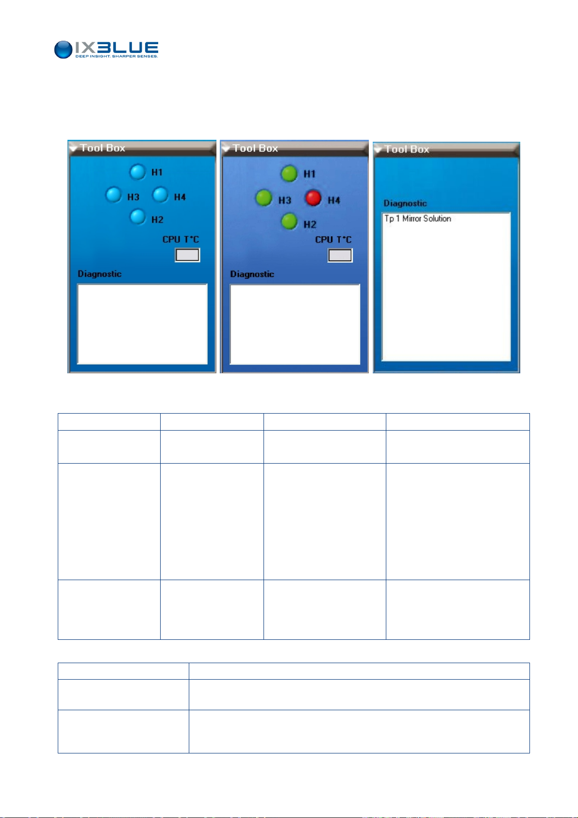
IV.3.3 LIST OF THE WARNING MESSAGES AND TROUBLESHOOTING
These messages appear in the tool boxes relative to the processor, the inertial sensor, the
acoustic array and the external sensor. For example:
GAPS – User Guide
Figure 59 - Diagnostic dialog box in the acoustic array toolbox
Processor
Warning Messages Meaning Possible Cause(s) Checks, possible solutions
Negative Stack Time
or Stack Error
Mirror Solution Solved ambiguity of two
Filter Attenuation Position smoothed by the
Timing error in the attitude
data array
symmetrical positioning
solutions
filter so it is accepted
CPU overload Reduce the recurrence
A hydrophone has not delivered
useful information (too much
noise, out of service …), the
three others worked properly.
Two positioning solutions are
found with three hydrophones.
The system has been able to
solve the ambiguity.
Very noisy raw data that trigger a
smoothing and predicting filter (if
you have activated this option).
Check the SNR in the MMI.
Check that it is not permanent and that
it does not concern always the same
hydrophone in the Acoustic Array
Status.
Reduce the general ambient noise. You
can for example reduce the speed or
the variable pitch of the propellers.
If it happens too often, check the
acoustic noise of the ship (see
convergence error below).
Inertial System
Warning Messages Meaning
Alignment Initialization of the inertial sensor (coarse alignment), it takes 5 minutes after powering of GAPS
and before being operational. It is better to let the ship drift during these 5 minutes.
Fine Alignment End of the initialization of the inertial sensor. It can take 30 minutes before being fully
operational. Caution: on a ship that is alongside the wharf, this final initialization can last
permanently.
MU-GAPS-AN-003 Ed. L – May 2012
85
Page 98
GAPS – User Guide
Acoustic Array There are no warning messages available.
External Sensors
Warning Messages Meaning
Pressure Not Used Pressure sensor data inconsistent with valid position computation. The pressure sensor data is
rejected.
GPS Data Invalid GPS data is not valid.
GPS Data Noisy GPS data is noisy.
GPS Data Rejected GPS data is rejected.
IV.3.4 ERROR MESSAGES
These messages appear in the tool boxes relative to the processor, the inertial sensor, the
acoustic array and the external sensor.
Processor
Error Messages Meaning Possible Cause(s) (not
exhaustive)
No Detection. None of the four hydrophones
is receiving any signal
Negative Travel Time Negative time found in travel
time computation
Convergence Error No convergence found in
position computation
If the message appears alone,
the transponder could not
transmit.
The transponder might be too
close to the GAPS antenna in
responder mode.
Anomaly in the detection process
of GAPS.
Turn around time of the
transponder different from the
value in the GAPS MMI and
transponder too close to the
GAPS antenna.
Noisy raw data Check the noise recorded by the
Checks, possible solutions
Check if the transponder transmits
(for example try to hear the ping).
Move the transponder away from
GAPS.
Turn off GAPS and after at least 20
seconds turn it on again.
Check if the values of the turn around
time in the MMI and in the
transponder are identical.
Check the external synchro.
Check for unexpected triggering of
the transponder due to heavy
acoustic noise for example.
antenna and try to reduce it (for
example slowing down the propeller
line shaft)
Velocity profile Error Error during application of
sound velocity profile
Not corrected sector
jump
Corrected sector jump Position found in a wrong
Position found in a wrong
angular sector below GAPS,
NOT corrected.
angular sector below GAPS,
position is now corrected.
The depth of the last layer of the
velocity profile is higher than the
computed depth of the
transponder.
Acoustic noise conditions
specially rough.
Acoustic noise conditions
specially rough.
MU-GAPS-AN-003 Ed. L – May 2012
Introduce an additional layer with a
greater depth than the actual depth of
the transponder.
Same as Convergence Error (if the
problem occurs in a repetitive way)
Same as Convergence Error (if the
problem occurs in a repetitive way)
86
Page 99
GAPS – User Guide
Error Messages Meaning Possible Cause(s) (not
exhaustive)
Mirror Ambiguity The system has entered in a
process to solve the ambiguity
between two possible solutions.
The process has not
succeeded.
Above Surface The computed position is
above the water surface. The
position is rejected.
Rejection Filter This alarm occurs when we
know that the computed
position is not valid. In this case
we do not feed the filter with
this position.
A hydrophone has not delivered
useful information (too much
noise, out of service …), the
three others worked properly.
Two positioning solutions are
found with three hydrophones.
The system has NOT been able
to solve the ambiguity.
Most probably the velocity profile
is erroneous because the
computed position is inconsistent
(in the air).
Inconsistent value compared to
the previous positions has been
rightfully rejected.
Checks, possible solutions
Check the SNR value in the MMI.
Reduce the general ambient noise.
You can for example reduce the
speed or the variable pitch of the
propellers.
Same as in Mirror Solution.
Check the velocity profile.
Perform again the acquisition of a
velocity profile.
If this stays an isolated event, there is
nothing to do.
In the opposite case, consider the
presence of reflections and multiple
travels of the acoustic wave. Increase
the recurrence value.
Reduce the general ambient noise as
in the convergence error and mirror
ambiguity.
Delta T Filter Error The date of emission of the
beacon is older than the date of
the position output by the filter.
The internal data flow is late due
to CPU overload.
Lower the Output rate of the user
protocol.
Contact iXBlue support
Inertial Sensor
Error Messages Meaning Possible Cause(s)
(not exhaustive)
ADC1 Saturation Overload on the ADC1 of the INS Contact iXBlue customer support
ADC2 Saturation Overload on the ADC2 of the INS Contact iXBlue customer support.
ADC3 Saturation Overload on the ADC3 of the INS Contact iXBlue customer support.
Accelerometer X1 Error Error on the accelerometer X1 of the INS Contact iXBlue customer support.
Accelerometer X2 Error Error on the accelerometer X2 of the INS Contact iXBlue customer support.
Accelerometer X3 Error Error on the accelerometer X3 of the INS Contact iXBlue customer support.
Heading Not Valid Heading data of the INS is not valid Message appears often
after an ADC Overload
or accelerometer error.
Attitude Not Valid Attitude data of the INS is not valid Message appears often
after a ADC Overload
or accelerometer error.
Checks, possible solutions
Wait a few minutes and all should
come back in order.
If not contact iXBlue customer
support.
Wait a few minutes and all should
come back in order.
If not contact iXBlue support.
MU-GAPS-AN-003 Ed. L – May 2012
87
Page 100
Acoustic Array
External Sensor
GAPS – User Guide
There are no error messages available.
Error Messages Meaning Possible Cause(s) (not
exhaustive)
GPS Not Received GPS data expected was not received
in input.
Pressure Not Received Pressure data expected was not
received in input.
GPS not properly connected,
defectuous cables (the Y
cable or the 10 m GPS
cable).
Unavailable satellites
Pressure sensor defectuous,
not properly connected, not
at the right format or serial
port not properly
configurated.
Checks, possible solutions
Check the cables and connections.
Check that the satellites are
available.
Check the input data of the ECB
($PMEVL, NMEA format), serial port
configuration …
MU-GAPS-AN-003 Ed. L – May 2012
88
 Loading...