

Page 1
SDR-2716
WT-716/WM-716
VHF PLL 16 CHANNEL WIRELESS SYSTEM
OPERATING MANUAL
Designed and Manufactured by
ITEC Tontechnik und
Industrieelektronik GesmbH
8200 Laßnitzthal 300
Austria / Europe
GREEN PRODUCT
It has been RoHS Compliant
GREEN PRODUCT
It has been RoHS Compliant
Page 2
2 www.itec-audio.com
MICROPHONES
ITEC 716 WIRELESS SYSTEMS
1. Introduction
Congratulation in owning one of these state-of-the-art PLL Synthesized 16 channels frequency
agile VHF high band (SDR-2716) professional wireless receivers. According to their frequency
range, these receivers are
designed to be matched with ITEC VHF high band PLL Synthesized transmitters (handheld or
beltpack).
The standard combinations are as follow:
SDR matches WT, or WM
As this is a shared operating manual of SDR-2716, we suggest you to read this
operating manual thoroughly in order to familiarize with each part of function before using.
(Frequency list, see page 11)
2. Receiver
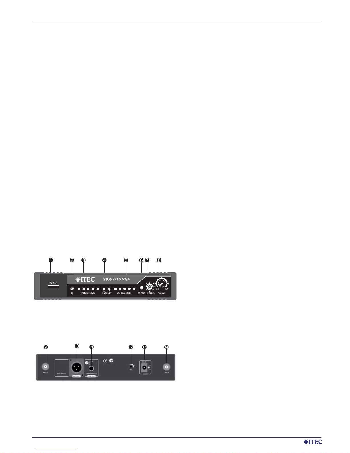
2.1 Diversity Receiver ITEC SDR-2716
1. Power switch
2. Power on indicator
3. RF signal indicator
4. Diversity indicator
5. AF signal indicator
6. RF test button
7. Channel selector
8. Volume control
9. Antenna B socket
10. XLR (balanced) audio output
11. Unbalanced audio output
12. Squelch (SQ) control
13. DC IN jack
14. Antenna A socket
SQ
SQ
12-1 5V
12-15V
DC-I N
DC-IN
ANT.B
ANT.B
ANT.A
ANT.A
BAL ANCED
BALANCED
UNBA LANCE D
UNBALANCED
1.GND
2.
3.
+
-
3
LINE O UT
LINE OUT
MIC OU T
MIC OU T
1
2
PLL DIVERSITY RECEIVER
Page 3
www.itec-audio.com 3
MICROPHONES
ITEC 716 WIRELESS SYSTEMS
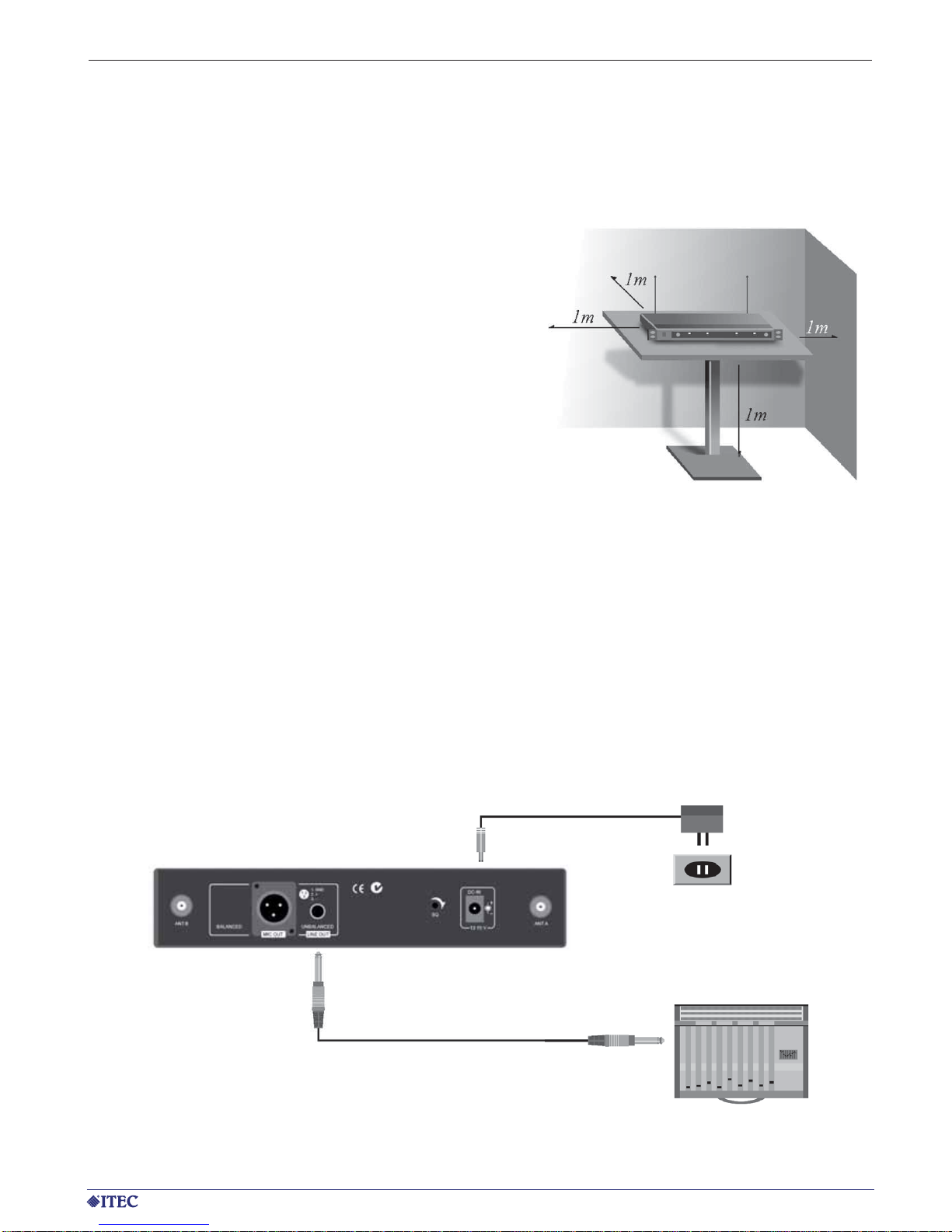
2.1.1. Receiver Installation
For best operation, the receiver should be at least 1m
above the ground and at least 1m away from a wall or
metal surface to minimize reflection. The transmitter
should also be at least 1m away from a wall or metal
surface to minimize reflection. The transmitter should
also be at least 1m away from the receiver, as shown
in Fig.1.
Keep antennas away from noise source such as
motors, automobiles, neon light as well as large metal
objects.
Fig. 1
2.1.2. Audio output connection
There are two audio outputs on the back of the Diversity SDR receivers. Mic-level balanced and
Line-level unbalanced. Use shielded audio cable for the connection between the receiver and the
mixer. If the mixer / amp is a 1/4“ phone jack, connect a cable from the 1/4“ unbalanced audio
output from the receiver to the mixer / amp. If the mixer has an XLR input, connect a cable from
the balanced XLR audio output from the receiver to the mixer input. Audio output connection is as
Fig.2.
Bild 2
Fig. 2
Page 4

4 www.itec-audio.com
MICROPHONES
ITEC 716 WIRELESS SYSTEMS
2.1.3. Rack Mounting
SDR series are 1/2 19“ casing design and the specially designed 19“ rack mount adapter (MP-50)
is available as optional purchase for customers‘ installation request. The installation instructions
are shown as Fig. 3.
Fig. 3
2.1.4. RF Interference
If you encounter receiving interference (from other than an operating TV station), often it can be
overcome by adjusting the receiver‘s squelch control, as described on 5.2 (below).Please note that
wireless frequencies are shared with other radio services. According to FCC regulations, wireless
microphone operations are unprotected from interference of other licensed operations in the band.
If any interference is received by any Government or non-Government operation, the wireless
microphone must cease operation. The above statement is valid in the U.S.A.
2.1.5. Receiver Squelch control
The squelch control on the back panel of the receiver is preset at the factory, but can be adjusted
if you must use the system in a high RF interference area. If there is audio output from the receiver
when your transmitter is OFF, adjust the squelch control so the system will receive the signal from
your transmitter but squelch or eliminate the unwanted background RF noise. This adjustment
can cause a reduction in usable range of the
wireless transmitter, so set the control to the lowest position which reliably mutes the unwanted RF
signal.
Page 5

www.itec-audio.com 5
MICROPHONES
ITEC 716 WIRELESS SYSTEMS
1. Capsule with metal grill
2. Battery Good indicator (green)
3. Battery Low indicator (red)
4. Power on/off switch
5. Channel switch
6. Charging contacts
3. Hand-Held Microphone WM716 (VHF)
3.1. Battery
These two microphones require 3 pieces of „AA„ size
batteries to operate.Please insert the batteries according
to the correct polarity indication. Remove the cover to
open the battery compartment as indicated in Fig.4.
Caution
Many batteries are known to have leakage problem of conductive and corrosive liquid. Please observe the rule to remove the batteries if they are not to be used for a period of a few days.
Due to various unstandardized sizes ( diameters ) of „ AA „ batteries, this battery compartment is
designed to accommodate the most commom Alkaline batteries only.
Fig. 4
Page 6

6 www.itec-audio.com
MICROPHONES
ITEC 716 WIRELESS SYSTEMS
4. Belt-Rack Transmitter WT716 (VHF)
4.1. Channel selection and gain
Channel selector and gain adjustment are hidden in the designated cover in the front as shown in
Fig. 7. To make channel selection and gain adjustment, please press the designated cover and flip
it open. Channel selection can be made by rotating the selector with a small screw driver.Gain adjustment for Lavalier and Headset microphones can be done by adjusting the MT switch, whereas
GT switch is for the gain adjust of electric Guitar and other high impedance line level inputs.
1. Battery status indicator
2. Power switch
3. Battery compartment
4. Charging point
5. Capsule
6. Mike clip
MTGT
13
13
1
2
1
2
11
11
1
0
1
0
9
8
7
6
5
WT-716
1
3
4
Fig. 7
Page 7

www.itec-audio.com 7
MICROPHONES
ITEC 716 WIRELESS SYSTEMS
5. Frequency list
VHF SDR 2716/WM 716/WT 716
EUV-232 EUV-243
canal frequency canal frequency canal frequency canal frequency
1 232.825 9 232.825 1 243.200 9 243.200
2 233.125 10 233.125 2 243.700 10 243.700
3 234.625 11 234.625 3 244.600 11 244.600
4 235.675 12 235.675 4 246.300 12 246.300
5 236.575 13 236.575 5 247.100 13 247.100
6 237.325 14 237.325 6 247.500 14 247.500
7 237.775 15 237.775 7 248.600 15 248.600
8 237.925 16 237.925 8 249.900 16 249.900
X XXX.XXX to prefer
EG Konformitätserklärung
Declaration of Conformity
Dokument-Nr./ 025-09
Document-No.
Hersteller/ ITEC Tontechnik und Industrieelektronik GesmbH
Manufacturer
Anschrift/ 8200 Lassnitzthal 300, Austria
Adress:
Produktbezeichnung/ Drahtlosmikrofone
Product name: Wireless microphones
Type/ ITEC WM-716, WT-716
Type:
Das bezeichnete Produkt stimmt mit den Vorschriften folgender Europäischer Richtlinien überein,
nachgewiesen durch die Einhaltung folgender Normen:
The above mentioned product has been manufactured according to the regulations of the following
European directives proven throug compliance with the following standards:
Normen / Generic standards
EMC: EN 301 489-1: V 1.5.1 : 2004, EN 301 489-9: V 1.3.1 : 2002
Radio: EN 300 422-2: v.1.1.1 : 2000, EN 300 422-1: v.1.2.2 : 2000
Safety: EN 60065:2002
Notified Body CE 0682!
ING. WERNER LOIBNER
Name/Name
Geschäftsführer / Managing Director
Stellung/Position
2009-02-02
Datum/Date Unterschrift/Signature
ITEC Tontechnik und Industrieelektronik GesmbH, A-8200 Laßnitzthal 300 / Austria / Europe
Tel.: +43 (0)3133/3780, Fax: +43 (0)3133/3780-9, ATU28706200, DVR: 0703109, HRB 3418 Landesgericht Graz, office@itec-audio.com
Diese Erklärung bescheinigt die Übereinstimmung mit den
genannten Richtlinien, beinhaltet jedoch keine Zusicherung
von Eigenschaften. Die Sicherheitsshinweise der mitgelieferten
Produktdokumentation sind zu beachten.
This declaration certifies compliance with the above mentioned
directives but does not include a property assurance.
The safety notes given in the product documentations, which are
part of the supply, must be observed.
Page 8

ITEC- Tontechnik und Industrieelektronik GesmbH, A-8200 Lassnitzthal 300 / Austria / Europe
Tel.: +43 (0)3133 / 3780-0, office@itec-audio.com, www.itec-audio.com
- SPECIFICATIONS
152
78 mm
38 mm
45 mm
213
150
GENERAL FEATURES OF THE SYSTEM
Maximum Frequency Deviation ± 40 kHz
Frequency Response 50 Hz – 18 kHz
Harmonic Distortion < 0,5 %
Signal-to-Noise Ratio > 103 dB
SUPPLY VOLTAGE
WT-716, WM-716
3 Alkaline batteries (AA) respectively 3 NiMH accumulators, 1800mAh
SDR-2716, SDR-716
12 – 15 VDC, circa 150 mA
RECEIVER SDR-2716
Indicators LED-chain for NF- and HF-levels, Diversity-display, Antenna A / B
NF-output MIC XLR-M 3-poles, balanced, 150 mV / 600 ohms
NF-output LINE Jack 6,3 mm, unbalanced, 1.5V / 15 kohms
Antenna connection 2 x TNC
Dimensions (W x H x D) 213 x 45 x 200 mm (9.5“ / 1 HU)
Weight 0,75 kg
Included accessories 2 5/8 Lambda antennas, wall power supply 230 VAC / 12 VDC
Optional accessories 19“ mounting adapter: Set 1 for one / Set 2 for 2 receivers
RECEIVER SDR-716
Indicators Diversity-display, Antenna A / B
All connections Connector strip 3.96 mm, 2 x 10-poles
Dimensions (W x H x D) 78 x 38 x 152 mm
Weight 0,15 kg
ITEC 716 WIRELESS SYSTEMS
 Loading...