

Page 1
SDR-5100M/SDR-5100
WT-5100/WM-5100
UHF PLL 100 CHANNEL WIRELESS SYSTEM
OPERATING MANUAL
GREEN PRODUCT
It has been RoHS Compliant
Page 2
2 www.itec-audio.com
MICROPHONES
ITEC 5100 WIRELESS SYSTEM
With the ITEC 5100 you have a modern and professional wireless microphone system in the UHF domain
available. The receivers (as the module receiver and the integrated 19” version) are true diversity receivers,
ensuring a high operating distance and an undisturbed reception without short-term loss of communication.
The innovative “pilot tone technique” offers a reliable protection against interferences caused by jamming
transmitters and prevents switching noise during on-off operations of the sender.
1. Introduction
Congratulation in owning one of these state-of-the-art Synthesized 100 channels frequency agile UHF high
band professional wireless receivers.
The system contains the following components:
Receiver Module Receiver Hand-held Transmitter Pocket Transmitter
ITEC SDR-5100 ITEC SDR-5100M WM-5100 WT-5100
We suggest you to read this operating manual thoroughly in order to familiarize with each part of function
before using.
2. Receiver
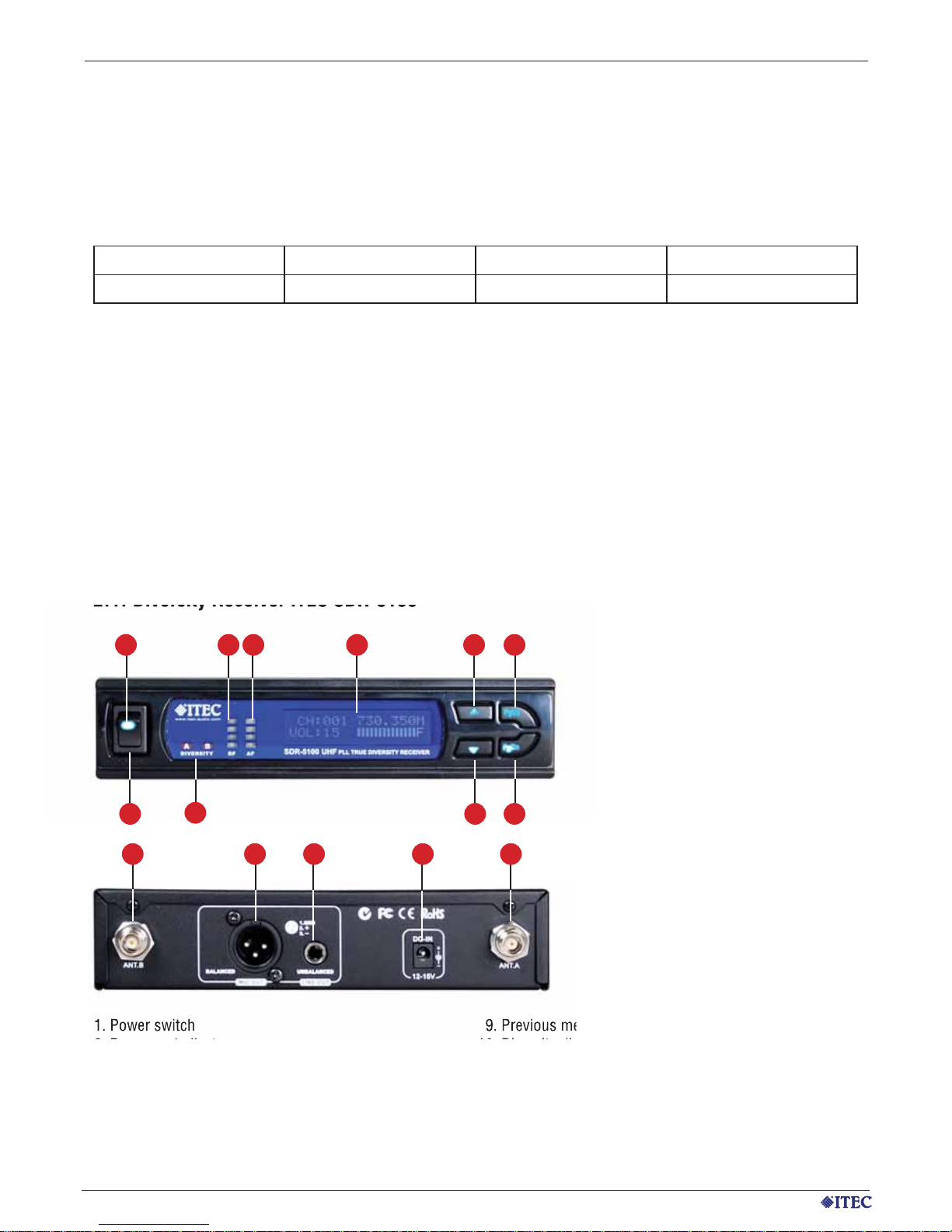
2.1. Diversity Receiver ITEC SDR-5100
1. Power switch
2. Power on indicator
3. RF signal indicator
4. AF signal indicator
5. Display
6. Frequency respectively Level +
7. Frequency respectively Level –
8. Next menu
9. Previous menu
10. Diversity display (antenna A/B)
11. Antenna B socket
12. XLR (balanced) audio output
13. Unbalanced audio output
14. DC IN jack
15. Antenna A socket
11 12 13 14 15
2 3 4 5 6 8
971
10
1.1. General features of the system
Page 3
www.itec-audio.com 3
MICROPHONES
ITEC 5100 WIRELESS SYSTEM
1 m
1 m
1 m
1 m
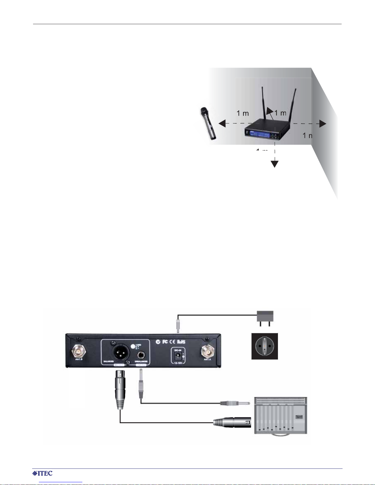
2.1.1. Receiver Installation
For best operation, the receiver should be at least
1m above the ground and at least 1m away from
a wall or metal surface to minimize refl ection. The
transmitter should also be at least 1m away from
a wall or metal surface to minimize refl ection. The
transmitter should also be at least 1m away from
the receiver, as shown in Fig. 1. Keep antennas
away from noise source such as motors, automobiles, Spotlights with serious connection unit,
neon light as well as large metal objects.
Fig. 1
2.1.2. Audio output connection
There are two audio outputs on the back of the Diversity SDR receivers. Mic-level balanced and Line-level
unbalanced. Use shielded audio cable for the connection between the receiver and the mixer. If the mixer / amp
is a 1/4“ phone jack, connect a cable from the 1/4“ unbalanced audio output from the receiver to the mixer / amp.
If the mixer has an XLR input, connect a cable from the balanced XLR audio output from the receiver to the mixer
input. Audio output connection is as Fig.2.
Bild 2
Fig. 2
or
Page 4
4 www.itec-audio.com
MICROPHONES
ITEC 5100 WIRELESS SYSTEM
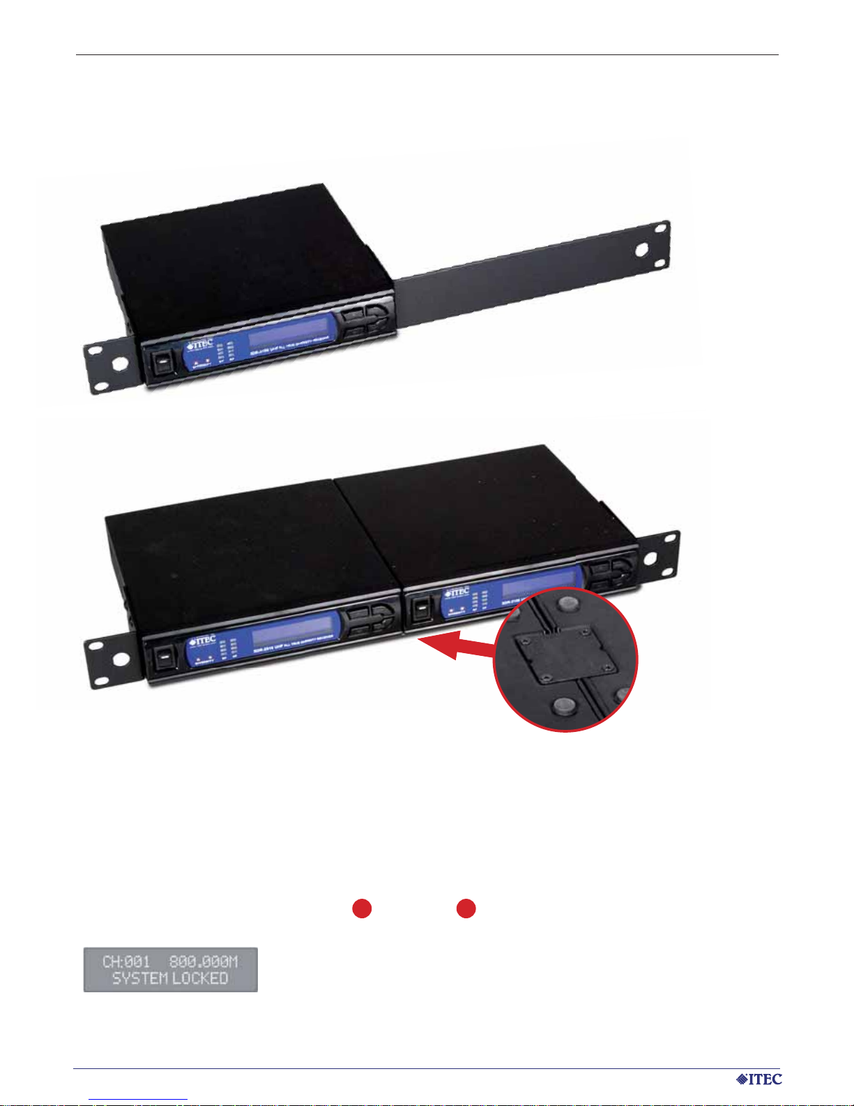
2.1.3. Rack Mounting
The ITEC SDR-5100 receiver is suitable for installations within 19” racks. For this purpose 2 different mounting
adapters are available (see picture 3 and 4)
Picture 4: Installation kit for two receivers (consisting of 2
short angle brackets and a union joint)
Picture 3: Installation kit for one receiver (consisting of a short and a long angle bracket)
2.1.4. Volume adjustment, channel selection and squelch set-up
2.1.4.1 Lock / unlock operation
In case the receiver is locked (as shown in the display), an unlock operation is required, before any adjustments
of the set-up are possible. Press the PgUp or the PrDn button for several seconds: After carrying out
the adjustments the locked mode can be reached in the same way again.
8 9
Page 5

www.itec-audio.com 5
MICROPHONES
ITEC 5100 WIRELESS SYSTEM
2.1.4.2 Volume adjustment
The volume can be adjusted directly on the main display by pressing the bottoms and in the range
between 0 and 15. The new adjustments are stored automatically and remain in the event of a power failure.
Note: Please wait a few seconds after the unlock operation, until the actual volume is displayed in the second
line of the display.
6 7
2.1.4.3 Channel selection / Frequency adjustment
Press the PgUp or the PrDn button until “CHANNEL/FREQUENCY” is displayed: Select the desired
frequency using the keys and . The new adjustments are stored automatically and remain in the
event of a power failure.
2.1.4.4 Squelch adjustment
Press the PgUp or the PrDn button until “SQUELCH SETUP” is displayed: Select the desired noise reduction by using the keys and in the range between 1 and 10. A high level indicates a high noise
reduction (possible reduction of operating range); a low value indicates a low noise reduction (maximum operating range). Due to the implemented “pilot tone method” the probability the receiver is impacted by a jamming
transmitter can be ruled out to a great extend. The device can be used in nearly all cases with minimum squelch
level and maximum operating range (set-up value 1). The new adjustments are stored automatically and remain
in the event of a power failure.
2.1.4.5 Auto Scan
The receiver contains a auto-scan function – an automatic search run: After starting the auto scan mode the
receiver searches for the next free frequency. Due to the fact that only a temporary situation is evaluated, a
frequency selection using the auto scan function is not recommendable.
2.1.5 Display of battery condition
The sender (WT-5100 respectively WM-5100) permanently transmits the battery condition to the receiver. In
case the battery voltage is too low at the sender microphone, the warning “TX BATTERY LOW” is displayed: The
battery in the microphone has to be replaced respectively the accumulator has to
be recharged.
2.1.6 Antennas
Included with the receiver are two 5/8-Lamda antennas offering additional gain in a fl exible, rubber coated
design and an angled TNC connector.
8 9
6 7
8 9
6 7
Page 6

6 www.itec-audio.com
MICROPHONES
ITEC 5100 WIRELESS SYSTEM
2 3
1
2 3 4 5 6 7
8
3. Hand-Held Microphone WM-5100 (UHF)
3.1 Changing of capsule
First unscrew the metal grill from the housing and take out the
capsule to be replaced. Then insert in a new capsule. Either
dynamic or condenser type can be chosen from location to
location.
1. Microphone capsule modul
2. Battery status LED
3. ON/OFF switch
4. LCD
5. Battery compartment
6. Rotating protective cap for controls
7. LOCK/UNLOCK
8. SET
9. UP
10. DOWN
11. Charging port
12. Name plate
2.2.1 Switching-on and level adjustment
is carried out via the combined switch on knob / level regulator .
2.2.2 Frequency adjustment (channel selection)
The desired channel is selected via the + keys. The number of the channel is shown on the display .
The corresponding frequency is shown within the frequency list.
2.2.3 Squelch adjustment
The squelch adjustment is carried out via a potentiometer knob . Turning it right (clockwise) increases the
threshold ( High noise reduction, possible reduction of operating range); turning it left (counterclockwise) decreases the threshold ( low noise reduction, maximum operating range): Due to the implemented “pilot tone
method” the probability the receiver is impacted by a jamming transmitter can be ruled out to a great extend. The
device can be used in nearly all cases with minimum squelch level and maximum operating range (potentiometer
knob turned to the most left position).
8
1
7
2.2. Diversity Module receiver ITEC SDR-5100M
1. Channel display
2. Channel selection (unit position)
3. Channel selection (decade)
4. Operation display
5. Diversity display (antenna A/B)
6. Scan
7. Squelch Set-up
8. On/Off switch plus level adjustment
2 3
Page 7

www.itec-audio.com 7
MICROPHONES
ITEC 5100 WIRELESS SYSTEM
3.2 Batteries
The WM-5100 is powered by 2 batteries of the type AA.
Please note, that in case of a battery exchange both batteries must be replaced by
a similar type at once. Be careful when inserting the batteries and check the correct
polarity: For both batteries the negative pole has to point towards the microphone
cap. The battery condition is shown on the LC display. The red battery indicator gives
information on the battery status as well: When turning on the system the indicator shines for about one second. A permanent signal is a warning for a low battery
condition.
Remark
Used batteries are hazardous waste and have to be disposed accordingly. Some batteries (in particular low-end
products) can leak after long storage period and cause corrosion and ruining of the battery contacts. Use high
quality alkaline batteries of known brands, which also offer a longer lifetime.
3.3 Operation with accumulators
If you use accumulators together with your wireless microphone and the ITEC charger, check that in the battery
case accumulators of the original manufacturer and no batteries are inserted. In case a replacement of the accumulators is needed use original parts only.
3.4 Changing the set-up
3.4.1 Making changes to Channel/Frequency
Use UP or DOWN button to go to the CHANNEL/ FREQUENCY page. Press SET for
about 2 seconds to activate the cursor. The cursor will fl ash to allow changes to be
made. Pressing UP or DOWN button will increase or decrease the channel number. The
corresponding frequency will change accordingly. When a desired channel is selected,
press SET for about 2 seconds or wait for about 5 seconds tostore the data in the
memory.
3.4.2 Making changes to Battery selection
Use UP or DOWN button to go to the Battery selection page. Press SET for about 2
seconds to activate the cursor. The cursor will fl ash to allow changes to be made.
Press UP or DOWN button to move the cursor to either NiMH (rechargeable battery)
or AKLN (Alkaline battery) position. When the desired battery has been selected,
press SET for about 2 seconds or wait for about 5 seconds to store the data in the
memory
Page 8

8 www.itec-audio.com
MICROPHONES
ITEC 5100 WIRELESS SYSTEM
1. Antenna
2. Batterie weak
3. Mini-XLR connector
4. Power on/off switch
5. LCD display
6. Charging port
7. Charging contacts
8. Lavalier microphones (optional)
9. Mic clip (optional)
4. Pocket transmitter WT-5100 (UHF)
4.2 Batteries
The WM-5100 is powered by 2 batteries of the type AA.
Please note, that in case of a battery exchange both batteries must be
replaced by a similar type at once. Be careful when inserting the batteries
and check the correct polarity: For both batteries the negative pole has
to point towards the microphone cap. The battery condition is shown
on the LC display. The red battery indicator gives information on the
battery status as well: When turning on the system the indicator shines
for about one second. A permanent signal is a warning for a low battery
condition.
Remark
Used batteries are hazardous waste and have to be disposed accordingly. Some batteries (in particular low-end
products) can leak after long storage period and cause corrosion and ruining of the battery contacts. Use high
quality alkaline batteries of known brands, which also offer a longer lifetime.
9
1
2
3
4
5
6
8
7
12
13
14
15 16
12. Set
13. Up
14. Down
15. GT level adjustment for line-in (guitar)
16. MT level adjustment for microphone
4.1 Suitable connection cable respectively microphone
The pocket sender WT-5100 can be connected to the line-out socket of other audio equipment via the
adaptor cable ITEC-MC12.A lapel microphone (Lavalier microphone, button microphone), which is suitable to the
WT-5100 the ITEC-MC-12 is offered. Head sets are available in various variants, e.g. ITEC-MI and accordingly
ITEC-MC.
Page 9

www.itec-audio.com 9
MICROPHONES
ITEC 5100 WIRELESS SYSTEM
4.3 Operation with accumulators
If you use accumulators together with your pocket sender and the ITEC charger, check that in the battery case
accumulators of the original manufacturer and no batteries are inserted. In case a replacement of the accumulators is needed use original parts only.
4.4 Ändern der Einstellungen
4.4.1 Making changes to Channel/Frequency
Use UP or DOWN button to go to the CHANNEL/ FREQUENCY page. Press SET for
about 2 seconds to activate the cursor. The cursor will fl ash to allow changes to be
made. Pressing UP or DOWN button will increase or decrease the channel number. The
corresponding frequency will change accordingly. When a desired channel is
selected, press SET for about 2 seconds or wait for about 5 seconds tostore the
data in the memory.
4.4.2 Making changes to Battery selection
Use UP or DOWN button to go to the Battery selection page. Press SET for about 2
seconds to activate the cursor. The cursor will fl ash to allow changes to be made.
Press UP or DOWN button to move the cursor to either NiMH (rechargeable battery)
or AKLN (Alkaline battery) position. When the desired battery has been selected,
press SET for about 2 seconds or wait for about 5 seconds to store the data in the
memory
4.4.3 Level Adjustment
The gain settings for lavalier and head set microphones can be adjusted via the “MT” control knob. The input
level for electronic guitars or other types of line-in signals can be adjusted via the “GT” control knob.
EG Konformitätserklärung
Declaration of Conformity
Hersteller/ ITEC Tontechnik und Industrieelektronik GesmbH
Manufacturer
Anschrift/ 8200 Lassnitzthal 300, Austria
Adress:
Produktbezeichnung/ Drahtlosmikrofone
Product name: Wireless microphones
Type/ ITEC WM-516, WM-5100, WT-516, WT-5100
Type:
Das bezeichnete Produkt stimmt mit den Vorschriften folgender Europäischer Richtlinien überein,
nachgewiesen durch die Einhaltung folgender Normen:
The above mentioned product has been manufactured according to the regulations of the following
European directives proven throug compliance with the following standards:
Normen / Generic standards
EMC: EN 301 489-1: V 1.8.1 (04/2008), EN 301 489-9: V 1.4.1 (11/2007)
Radio: EN 300 422-2: v.1.2.2 (03/2008), EN 300 422-1: v.1.3.2 (03/2008)
Safety: EN 60065:2002/A1:2006/A11:2008
Notifi ed Body CE 0681!
ING. WERNER LOIBNER
Name/Name
Geschäftsführer / Managing Director
Stellung/Position
2009-02-02
Datum/Date Unterschrift/Signature
ITEC Tontechnik und Industrieelektronik GesmbH, A-8200 Laßnitzthal 300 / Austria / Europe
Tel.: +43 (0)3133/3780, Fax: +43 (0)3133/3780-9, ATU28706200, DVR: 0703109, HRB 3418 Landesgericht Graz, offi ce@itec-audio.com
Diese Erklärung bescheinigt die Übereinstimmung mit den
genannten Richtlinien, beinhaltet jedoch keine Zusicherung
von Eigenschaften. Die Sicherheitsshinweise der mitgelieferten
Produktdokumentation sind zu beachten.
This declaration certifi es compliance with the above mentioned
directives but does not include a property assurance.
The safety notes given in the product documentations, which are
part of the supply, must be observed.
Page 10
9GMY766 (766MHz-786MHz)
Chanel Fequenz Chanel Fequenz Chanel Frequency Chanel Frequency Chanel Frequency Chanel Frequency
1 766,100 18 783,500 35 770,350 52 775,150 69 780,250 86 784,000
2 766,700 19 784,400 36 770,650 53 775,450 70 780,550 87 784,100
3 767,500 20 784,850 37 770,950 54 775,750 71 780,850 88 784,300
4 768,200 21 766,300 38 771,100 55 776,050 72 781,150 89 784,450
5 768,850 22 766,600 39 771,400 56 776,350 73 781,450 90 784,600
6 771,000 23 766,900 40 771,700 57 776,650 74 781,750 91 784,750
7 772,100 24 767,200 41 772,000 58 776,950 75 782,050 92 784,900
8 772,900 25 767,500 42 772,150 59 777,250 76 782,200 92 785,050
9 774,300 26 767,800
43 772,450 60 777,550 77 782,500 94 785,200
10 775,500 27 768,100 44 772,750 61 777,850 78 782,650 95 785,350
11 776,400 28 768,400 45 773,050 62 778,150 79 782,800 96 785,500
12 776,850 29 768,700 46 773,350 63 778,450 80 782,950 97 785,650
9GMY766 (766MHz-786MHz)
Chanel Fequenz Chanel Fequenz Chanel Frequency Chanel Frequency Chanel Frequency Chanel Frequency
13 778,350 30 769,000 47 773,650 64 778,750 81 783,100 98 758,800
14 779,100 31 769,300 48 773,950 65 779,050 82 783,250 99 785,950
15 780,150 32 769,600 49 774,250 66 779,350 83 783,400 100 786,100
16 780,750 33 769,900 50 774,550 67 779,650 84 783,700
17 782,300 34 770,200 51 774,850 68 779,950 85 783,850
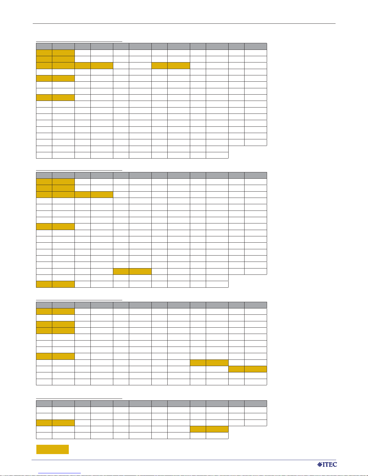
X XXX.XXX to prefer
10 www.itec-audio.com
MICROPHONES
ITEC 5100 WIRELESS SYSTEM - UHF SDR 5100/WM 5100/WT 5100 - FREQUENCY LIST
9GMY710 (710MHz-730MHz)
Chanel Fequenz Chanel Fequenz Chanel Frequency Chanel Frequency Chanel Frequency Chanel Frequency
1 710,300 18 727,500 35 714,500 52 719,300 69 723,950 86 728,000
2 711,500 19 728,400 36 714,800 53 719,600 70 724,100 87 728,150
3 712,400 20 728,850 37 714,950 54 719,900 71 724,400 88 728,300
4 712,850 21 730,350 38 715,250 55 720,200 72 724,700 89 728,400
5 714,350 22 710,600 39 715,550 56 720,500 73 725,000 90 728,600
6 715,100 23 710,900 40 715,850 57 720,650 74 725,300 91 728,750
7 716,150 24 711,200 41 716,000 58 720,950 75 725,600 92 728,850
8 716,750 25 711,500 42 716,300 59 721,250 76 725,900 92 729,050
9 718,300 26 711,800
43 716,600 60 721,550 77 726,200 94 729,200
10 719,500 27 712,100 44 716,900 61 721,850 78 726,500 95 729,350
11 720,400 28 712,400 45 717,200 62 722,150 79 726,800 96 729,500
12 720,850 29 712,700 46 717,500 63 722,450 80 727,100 97 729,650
13 722,350 30 713,000 47 717,800 64 722,750 81 727,250 98 729,800
14 723,100 31 713,300 48 718,100 65 723,050 82 727,400 99 729,950
15 724,150 32 713,600 49 718,400 66 723,350 83 727,500 100 730,100
16 724,750 33 713,900 50 718,700 67 723,650 84 727,700
17 726,300 34 714,200 51 719,000 68 723,800 85 727,850
9GMY730 (730MHz-750MHz)
Chanel Fequenz Chanel Fequenz Chanel Frequency Chanel Frequency Chanel Frequency Chanel Frequency
1 730,350 18 747,500 35 734,100 52 739,050 69 744,000 86 748,200
2 731,100 19 748,400 36 734,400 53 739,350 70 744,300 87 748,350
3 732,150 20 748,850 37 734,700 54 739,650 71 744,600 88 748,500
4 732,750 21 750,350 38 735,000 55 739,950 72 744,900 89 748,650
5 734,300 22 730,650 39 735,300 56 740,250 73 745,200 90 748,800
6 735,500 23 730,950 40 735,600 57 740,550 74 745,500 91 748,950
7 736,400 24 731,250 41 735,900 58 740,700 75 745,800 92 749,100
8 736,850 25 731,550 42 736,050 59 741,000 76 746,100 92 749,250
9 738,350 26 731,850
43 736,350 60 741,300 77 746,400 94 749,400
10 739,100 27 732,150 44 736,650 61 741,600 78 746,700 95 749,550
11 740,150 28 732,300 45 736,950 62 741,900 79 747,000 96 749,700
12 740,750 29 732,600 46 737,250 63 742,200 80 747,300 97 749,850
13 742,350 30 732,750 47 737,550 64 742,500 81 747,450 98 750,000
14 743,100 31 733,050 48 737,850 65 742,800 82 747,600 99 750,150
15 744,150 32 733,200 49 738,150 66 743,100 83 747,750 100 750,300
16 744,750 33 733,500 50 738,450 67 743,400 84 747,900
17 746,300 34 733,800 51 738,750 68 743,700 85 748,050
Page 11

www.itec-audio.com 11
MICROPHONES
ITEC 5100 WIRELESS SYSTEM - UHF SDR 5100/WM 5100/WT 5100 - FREQUENCY LIST
9HOL654 (654MHz-674MHz)
Chanel Fequenz Chanel Fequenz Chanel Frequency Chanel Frequency Chanel Frequency Chanel Frequency
1 654,300 18 671,500 35 658,500 52 663,300 69 667,950 86 672,000
2 655,500 19 672,400 36 658,800 53 663,600 70 668,100 87 672,150
3 656,400 20 672,850 37 658,950 54 663,900 71 668,400 88 672,300
4 656,850 21 674,350 38 659,250 55 664,200 72 668,700 89 672,450
5 658,350 22 654,600 39 659,550 56 664,500 73 669,000 90 672,600
6 659,100 23 654,900 40 659,850 57 664,650 74 669,300 91 672,750
7 660,100 24 655,200 41 660,000 58 664,950 75 669,600 92 672,900
8 660,750 25 655,500 42 660,300 59 665,250 76 669,900 92 673,050
9 662,300 26 655,800
43 660,600 60 665,550 77 670,200 94 673,200
10 663,500 27 656,100 44 660,900 61 665,850 78 670,500 95 673,350
11 664,400 28 656,400 45 661,200 62 666,150 79 670,800 96 673,500
12 664,850 29 656,700 46 661,500 63 666,450 80 671,100 97 673,650
13 666,350 30 657,000 47 661,800 64 666,750 81 671,250 98 673,800
14 667,100 31 657,300 48 662,100 65 667,050 82 671,400 99 673,950
15 668,150 32 657,600 49 662,400 66 667,350 83 671,550 100 674,100
16 668,750 33 657,900 50 662,700 67 667,650 84 671,700
17 670,300 34 658,200 51 663,000 68 667,800 85 671,850
9EU863 (863MHz-865MHz)
Chanel Fequenz Chanel Fequenz Chanel Frequency Chanel Frequency Chanel Frequency Chanel Frequency
1 863,050 4 863,425 7 863,800 10 864,175 13 864,550 15 864,800
2 863,175 5 863,550 8 863,925 11 864,300 14 864,675 16 864,925
3 863,000 6 863,675 9 864,050 12 864,425
9GMY823 (823MHz-831MHz)
Chanel Fequenz Chanel Fequenz Chanel Frequency Chanel Frequency Chanel Frequency Chanel Frequency
1 823,125 18 829,575 35 825,450 52 826,800 69 828,150 86 829,425
2 823,975 19 830,450 36 825,525 53 826,875 70 828,225 87 829,500
3 824,850 20 830,975 37 825,600 54 826,950 71 828,300 88 829,575
4 825,150 21 831,050 38 825,675 55 827,025 72 828,375 89 829,650
5 825,475 22 831,125 39 825,750 56 827,100 73 828,450 90 829,725
6 826,200 23 831,200 40 825,825 57 827,175 74 828,525 91 829,800
7 827,400 24 831,275 41 825,900 58 827,250 75 828,600 92 829,875
8 828,175 25 824,625 42 825,975 59 827,325 76 828,675 93 830,950
9 829,975 26 824,700
43 826,050 60 827,475 77 828,750 94 830,025
10 830,325 27 824,775 44 826,125 61 827,550 78 828,825 95 830,100
11 824,650 28 824,925 45 826,275 62 827,625 79 828,900 96 830,175
12 826,225 29 825,000 46 826,350 63 827,700 80 828,975 97 830,250
13 826,750 30 825,075 47 826,425 64 827,775 81 829,050 98 830,400
14 827,125 31 825,15 48 826,500 65 827,850 82 829,125 99 830,475
15 828,425 32 825,225 49 826,575 66 827,925 83 829,200 100 830,550
16 828,750 33 825,300 50 826,650 67 828,000 84 829,275
17 829,250 34 825,375 51 826,725 68 828,075 85 829,350
9HOL613 (613MHz-638MHz)
Chanel Fequenz Chanel Fequenz Chanel Frequency Chanel Frequency Chanel Frequency Chanel Frequency
1 613,350 18 634,525 35 632,350 52 628,300 69 624,350 86 620,975
2 614,525 19 635,100 36 633,300 53 629,925 70 637,500 87 621,725
3 615,925 20 636,525 37 633,950 54 632,125 71 626,500 88 623,375
4 617,025 21 613,475 38 634,725 55 632,525 72 628,550 89 624,375
5 618,750 22 614,650 39 635,300 56 633,475 73 630,175 90 637,775
6 620,350 23 616,050 40 636,850 57 634,125 74 632,375 91 626,625
7 621,100 24 617,150 41 613,725 58 634,900 75 632,775 92 628,675
8 622,750 25 618,875 42 614,900 59 635,475 76 633,725 93 630,300
9 623,750 26 620,475
43 616,300 60 637,275 77 634,375 94 632,500
10 624,850 27 621,225 44 617,400 61 613,950 78 635,150 95 632,900
11 625,875 28 622,875 45 619,125 62 615,125 79 635,752 96 633,850
12 627,925 29 623,875 46 620,725 63 616,525 80 637,750 97 634,500
13 629,550 30 636,650 47 621,475 64 617,625 81 613,975 98 635,275
14 631,750 31 626,075 48 623,125 65 619,350 82 615,150 99 635,850
15 632,150 32 628,125 49 624,125 66 620,950 83 616,550 100 637,900
16 633,100 33 629,750 50 637,100 67 621,700 84 617,650
17 633,750 34 631,950 51 626,250 68 623,350 85 619,375
Page 12

ITEC 5100 WIRELESS SYSTEM - SPECIFICATIONS
GENERAL FEATURES OF THE SYSTEM
Maximum Frequency Deviation ± 40 kHz
Frequency Response 50 Hz – 18 kHz
Harmonic Distortion < 0,5 %
Signal-to-Noise Ratio > 103 dB
SUPPLY VOLTAGE
WT-5100, WM-5100
2 Alkaline batteries (AA) respectively 2 NiMH accumulators, 1800mAh
SDR-5100, SDR-5100M
12 – 15 VDC, circa 150 mA
RECEIVER SDR-5100
Indicators LED-chain for NF- and HF-levels, Diversity-display, Antenna A / B
Display graphical LCD, blue backlight
NF-output MIC XLR-M 3-poles, balanced, 150 mV / 600 ohms
NF-output LINE Jack 6,3 mm, unbalanced, 1.5V / 15 kohms
Antenna connection 2 x TNC
Dimensions (W x H x D) 200 x 45 x 213 mm (9.5“ / 1 HU)
Weight 1,1 kg
Included accessories 2 5/8 Lambda antennas, wall power supply 230 VAC / 12 VDC
Optional accessories 19“ mounting adapter: Set 1 for one / Set 2 for 2 receivers
RECEIVER SDR-5100M
Indicators Diversity-display, Antenna A / B
Display 2-digits LED 7-Segment display, red
All connections Connector strip 3.96 mm, 2 x 10-poles
Dimensions (W x H x D) 78 x 38 x 152 mm
Weight 0,15 kg
ITEC- Tontechnik und Industrieelektronik GesmbH, A-8200 Lassnitzthal 300 / Austria / Europe
Tel.: +43 (0)3133 / 3780-0, offi ce@itec-audio.com, www.itec-audio.com
152 mm
78 mm
38 mm
45 mm
200 mm
213 mm
12 www.itec-audio.com
MICROPHONES
 Loading...