

Page 1

深圳市金合讯科技有限公司,0755-36853282,18664341585
IT6605 HDMI 1.4 3D Receiver
Programming Guide
Ver 1.00
Tseng, Jau-Chih
ITE T ech.
Last Update Date: 2010/12/07
Page 2

深圳市金合讯科技有限公司,0755-36853282,18664341585
History
2010/08/10 – Created by Tseng, Jau-chih
2010/08/1 1 – Added Audio Part.
2010/12/07 – Added HDCP part.
Page 3

深圳市金合讯科技有限公司,0755-36853282,18664341585
Index
Chap 1 Introduction..................................................................................................................1
Chap 2 Initial Progress .............................................................................................................2
Initial Progress..............................................................................................................................................2
Initial Value List ...........................................................................................................................................2
Chap 3 Video Output.................................................................................................................4
Video Output Flow .......................................................................................................................................4
Video Path....................................................................................................................................................5
Video Input Selection ...................................................................................................................................5
Video Output Configuration .........................................................................................................................6
Color Space Matrix.......................................................................................................................................7
Video I/O and Video Data I/O Tristate..........................................................................................................8
Event of Video Process.............................................................................................................................9
Video input mode resolution.......................................................................................................................10
Video CDR Reset........................................................................................................................................ 10
Chap 4 Audio Output...............................................................................................................11
Audio Control Registers.............................................................................................................................11
HDMI Audio Input Status...........................................................................................................................12
Audio Output Configure.............................................................................................................................13
Default Setting .......................................................................................................................................13
I2S mode and word length......................................................................................................................13
Output LPCM Audio on I2S Channel.........................................................................................................14
Output LPCM Audio on SPDIF Channel....................................................................................................14
Output NLPCM Audio on I2S Channel ......................................................................................................14
Output NLPCM Audio on SPDIF Channel.................................................................................................15
Output High Bit Rate on I2S Channel ........................................................................................................15
Output High Bit Rate on SPDIF Channel...................................................................................................15
Output LPCM/NLPCM Audio with Force Fs setting..................................................................................15
Error Handling ................................................................................................................. ........................... 16
Chap 5 HDMI Infoframe.........................................................................................................17
Chap 6 HDCP Support............................................................................................................19
HDCP Repeater setting...............................................................................................................................19
HDCP registers for repeater function .....................................................................................................21
HDCP Debug Status...............................................................................................................................22
Chap 7 3D Support..................................................................................................................23
Part 2 – Software Release Code Reference.....................................................................................26
Chap 8 Introduce.....................................................................................................................26
Chap 9 Flow............................................................................................................................27
Chap 10 Data T ype....................................................................................................................30
Chap 11 Sample Code Required Interface................................................................................31
Chap 12 Software Interface.......................................................................................................32
-i
Page 4

深圳市金合讯科技有限公司,0755-36853282,18664341585
IT6605 PROGRAMMING GUIDE
Chap 1 Introduction
The IT6605 is a dual-port HDMI 1.4 receiver. The IT6605 with its Deep Color capability (up to 36-bit)
ensures robust reception of high-quality uncompressed video content, along with state-of-the-art
uncompressed and compressed digital audio content such as DTS-HD and Dolby TrueHD in digital
televisions and projectors.
Aside from the various video output formats supported, the IT6605 also receives and provides up to 8
channels of I
facilitating direct connection to industry-standard low-cost audio DACs. Also, an S/PDIF output is
provided to support up to compressed audio of 192kHz frame rate. Super Audio Compact Disc (SACD)
is supported at up to 8 channels and 88.2kHz through DSD (Direct Stream Digital ports) ports.
Each IT6605 comes preprogrammed with an unique HDCP key, in compliance with the HDCP 1.2
standard so as to provide secure transmission of high-definition content. Users of the IT6605 need not
purchase any HDCP key s or ROM s .
To program IT6605 need using I
under 100KHz. The I
PCADR (pin105) value.
To access the IT6605 internal registers should by the following protocol:
Read:
<I2C start>-<0x90|w >-<register index>-<I2C repeater start>-<0x90|r>-<data>(-…-<data>)-<I2C Stop>
Write:
<I2C start>-<0x90|w >-<register index>-<data>(-…-<data>)-<I2C Stop>
In the following document, the register with index will present as Reg<idx>.
Eg: Reg05 means the register with index 0x05.
2
S digital audio outputs, with sampling rate up to 192kHz and sample size up to 24 bits,
2
2
C address for accessing internal registers are 0x90 or 0x92 depends on the
C access the PCSDA (pin26) and PCSCL (pin27) with the frequency
ITE Tech.
-1- 2010/12/07
Page 5

深圳市金合讯科技有限公司,0755-36853282,18664341585
IT6605 PROGRAMMING GUIDE
Chap 2 Initial Progress
The first step of initial IT6605 is to reset the chip.
Activate SYSRSTN (pin100) with low voltage or write reg05[4] = ‘1’, will reset the chip.
When SYSRSTN is high voltage and reg05[4] = ‘0’, IT6605 is under normal operating mode.
Initial Progress
Set HPD (HDMI Connection Pin19) to low (if possible).
Reg06 = 0x00 to power on all modules.
Reg07[3:2] = ‘11’ to turn off the termination.
Reg05 = 0xA1
Reg16 = 0x0F
Reg17 = 0x07
Reg18 = 0x07
Reg8C = 0x00 (5~8 is for initial interrupt mask setting)
Load the default value.
Configure the HDCP repeater setting
Receiver mode, reg73[7:4] = ‘0000’
Repeater mode, reg73[7:4] = ‘1000’
Delay about 500ms to make sure the HPD off enough.
Reg07[3:2] = ‘00’
Set HPD to high (if possible).
Initial Value List
reg05 = 0x20
reg08 = 0xAE
reg1D = 0x20
reg3B=0x40
reg56=0x01
reg68=0x03
reg6B=0x11
Reg6C=0x00
Reg93=0x43
Reg94=0x4F
Reg95=0x87
ITE Tech.
-2- 2010/12/07
Page 6

深圳市金合讯科技有限公司,0755-36853282,18664341585
Reg96=0x33
Reg97=0x0E
Reg9B=0x01
IT6605 PROGRAMMING GUIDE
Reg1A/Reg1B/Reg1C/R eg 3 D[7:6] for the output video format, refer to
Reg75/Reg76/Reg78 for the output audio format, refer to
Audio Output.
Video Output.
ITE Tech.
-3- 2010/12/07
Page 7

深圳市金合讯科技有限公司,0755-36853282,18664341585
IT6605 PROGRAMMING GUIDE
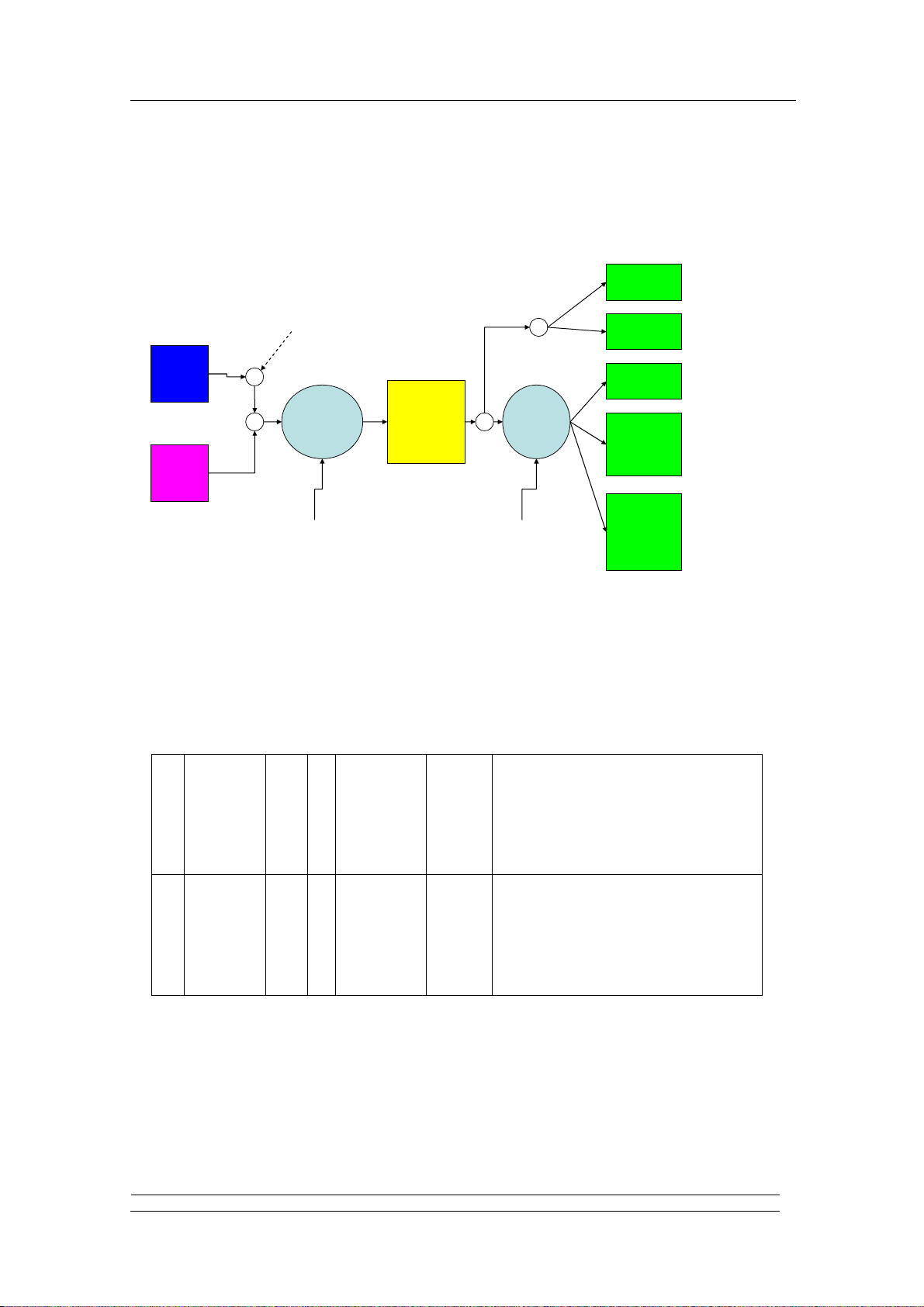
Chap 3 Video Output
IT6605 receive the HDMI or DVI video input, and output up to 30 bit TTL with numerous format, this
chapter describe how to configure the video path and video output.
Video Output Flow
IT6605 output video when it got a valid video input.
10 Sys_state RO
7 RXPLL_LOCK HDMI PLL locked
6 RXCK_Speed ‘1’ – Lower than 80MHz
‘0’ – Higher than 80MHz
5 RXCK_VALID ‘1’ – RX CLK Valid
4 HDMI_MODE ‘1’ – HDMI Mode
‘0’ – DVI Mode
Only reliable when SCDT on.
3 P1_PWR5V_DET (For CAT6023/IT6605)
‘1’ for HDMI input port 1 with
5V presented
2 SCDT ‘1’ – Sync Detected.
‘0’ – Otherwise.
1 VCLK_DET ‘1’ – VCLK Detect
‘0’ – Otherwise
0 PWR5V_DET ‘1’ - HDMI input port 0 with 5V
present.
The following steps are for getting the valid vi deo output:
IT6605 should detect 5V in corresponding HDMI port.
IT6605 gets valid SCDT (with SCDT status bit present and no SCDT off interrupt present).
Configure the video path of IT6605.
Reset video FIFO (reg1C[1] = ‘1’ → ‘0’).
Turn off the video I/O and video data tri-state.
ITE Tech.
-4- 2010/12/07
Page 8
深圳市金合讯科技有限公司,0755-36853282,18664341585
IT6605 PROGRAMMING GUIDE
Video Path
The video path of IT6605 are defined with video input, color space converting, and video output signal
format, as the figure:
Force Indicate
RGB 444
Input Color mode
DVI
Input
HDMI
Input
to RGB444
422 to 444
converting
Up/Down
Filter
Color
Space
Convert
Up/Down
Filter
444 to 422
converting
YCbCr444
YCbCr422
YCbCr422
Embedded
Sync
YCbCr422
Embedded
Sync
CCIR656
HDMI input contain up to 36 bits (which IT6605 su pported) RGB444, YCbCr444, or YCbCr422
TMDS input with AVI infoframe indicated. DVI input supports only RGB444 video input. The input
color are indicated by reg20 or AVI infoframe, and convert to output color space by color space
converting matrix (CSC Matrix), then output by color mapping registers and output format controls
registers
1B Video_map W/R
6
5
4
3
2
1
0
1C Video_Ctrl1 W/R 7
6
5
4
3
2
1
0
chSyncpol
Swap_O16b
Swap_Ch422
Swap_OutRB
Swap_ML
Swap_Pol
Swap_RB
DNFreeGo
SyncEmb
EN_Dither
EnUdFilt
OutDDR
2x656CLK
656FFRst
EnAVMuteRst
0000000 Referring to the map table of Emily.
0x00 Default: dithering and up/dn filter is enabled
2x656CLK:
1:an 2x 656CLK is generated by PLL
0:no 2x656 CLK
The detail step are describe in following section.
Video Input Selection
When SCDT and RXCK_Valid are both present, the video input is reliable. If the HDMI_MODE bit is
‘0’, the input is an DVI input mode and default treated as 24bit RGB444 video input, otherwise the
input mode should be explained as an HDMI mode with AVI infoframe supported. If the AVI infoframe
is not presented, some testing case ask HDMI Rx to receive the input video as an RGB444 mode.
ITE Tech.
-5- 2010/12/07
Page 9
深圳市金合讯科技有限公司,0755-36853282,18664341585
IT6605 PROGRAMMING GUIDE
Forcecolmod:
20 CSC_CTRL W/R 7
6
5
4
3:2
1:0
VDGatting
VDIOLDisable
VIOSel
ForceColMod
ColMod_Set
CSCSel
For DVI mode, the register setting should be reg20[4] = ‘1’ to ignore the AVI Infoframe bit value, and
set reg20[3:2] = ‘00’ as RGB444 mode.
For HDMI mode, to refer the AVI infoframe color mode, reg20[4] should be ‘0’ that IT6605 will refer
the AVI infoframe PB[1][6:5] as input color mode.
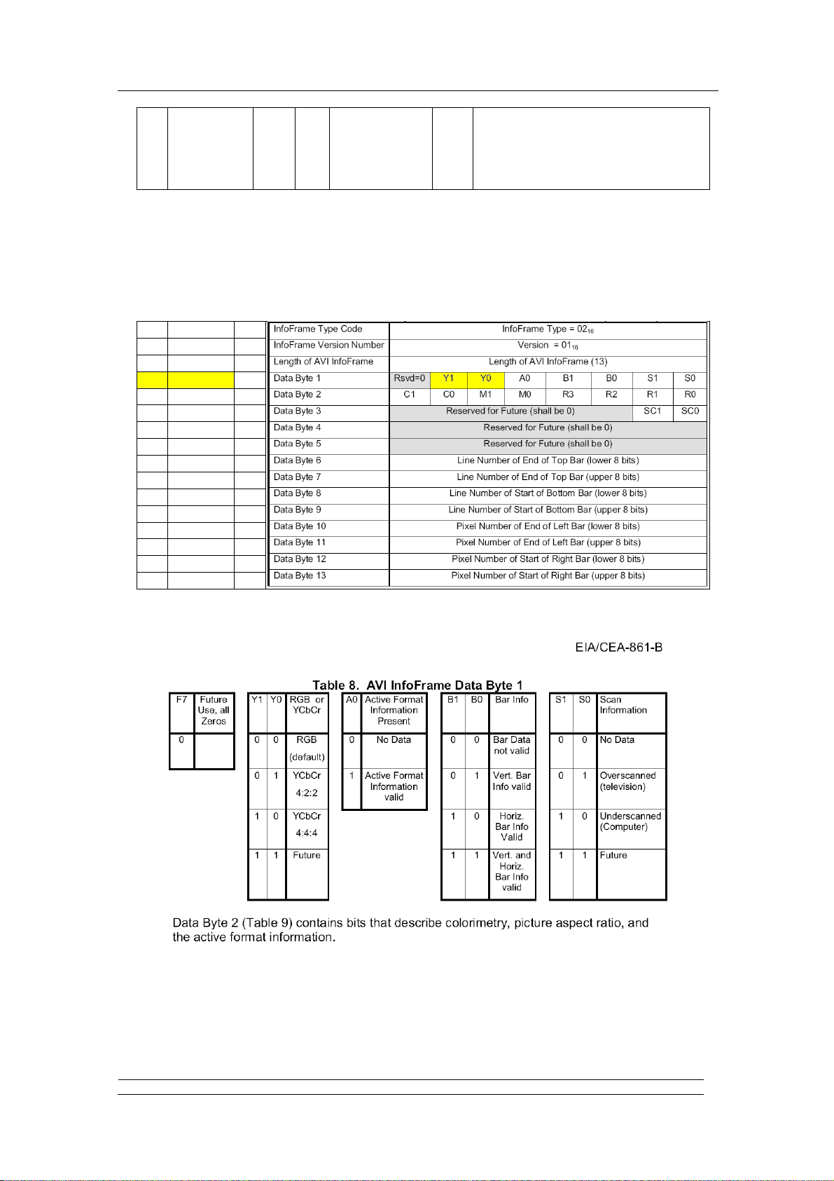
The received AVI infoframe of IT6605 is stored in regAD ~ regBA with 13 bytes.
AB AVI_leng RO
AC AVI_VER RO
AD AVI_DB0 RO
AE AVI_DB1 RO
AF AVI_DB2 RO
B0 AVI_DB3 RO
B1 AVI_DB4 RO
B2 AVI_DB5 RO
B3 AVI_DB6 RO
B4 AVI_DB7 RO
B5 AVI_DB8 RO
B6 AVI_DB9 RO
B7 AVI_DB10 RO
B8 AVI_DB11 RO
B9 AVI_DB12 RO
BA AVI_DB13 RO
0x00
0:color mode auto adjusted according to AVI
info
1: color mode is forced by register
Where Y1/Y0 are defined in CEA861/B spec, as following figure:
IT6605 will refer the input color space by regAE[6:5] or reg20[3:2] by reg20[4] selection, to decid e the
decoding of input colors.
Video Output Configuration
The video output format are controlled by reg1B and reg1C, and the output selection are controlled as
ITE Tech.
-6- 2010/12/07
Page 10

深圳市金合讯科技有限公司,0755-36853282,18664341585
following table:
IT6605 PROGRAMMING GUIDE
1B Video_map W/R
1C Video_Ctrl1 W/R 7
Reg1B
Video_map
6 5 4 3 2 1 0 7 6 5 4 3 2 1 0
Sync separated
RGB444
XX X
chSyncpol
6
Swap_O16b
5
Swap_Ch422
4
Swap_OutRB
3
Swap_ML
2
Swap_Pol
1
Swap_RB
0
DNFreeGo
SyncEmb
6
EN_Dither
5
EnUdFilt
4
OutDDR
3
2x656CLK
2
656FFRst
1
EnAVMuteRst
0
chSyncpol
Swap_O16b
0000000 Referring to the map table of Emily.
0x00 Default: dithering and up/dn filter is enabled
Swap_Ch422
Swap_OutRB
Swap_ML
Swap_Pol
2x656CLK:
1:an 2x 656CLK is generated by PLL
0:no 2x656 CLK
Reg1C
Video_Ctrl1
Swap_RB
DNFreeGo
SyncEmb
EN_Dither
EnUdFilt
OutDDR
2x656CLK
656FFRst
EnAVMuteRst
Sync separated
YCbCr444
Sync separated
24 bit YCbCr422
Sync separated
16 bit YCbCr422
Sync Embedded
16 bit YCbCr 422
Sync Embedded
8 bit YCbCr 422
(CCIR656)
XX X
X X
√ X X √ √ √
√ X X √ √ √ √
√ X X √ √ √ √ √
√ : Must set
X : Depends on the output mapping.
The above setting only decide the output signal format, the output color space are defined in the reg3D,
for determining the output:
Reg Name Type Bit Name Default value Description.
3D PG_CTRL2 W/R 7:6 OutColMod 10 ‘00’ – RGB444
‘01’ – YCbCr422
‘10’ – YCbCr444
To set RGB444, YCbCr422, or YCbCr444 also need to set reg3D[7:6] value.
Usually the output configuration is fixed in one type, thus the setting could be th e initial value.
Color Space Matrix
The color space register are defined in reg21~reg35, as following:
ITE Tech.
-7- 2010/12/07
Page 11
深圳市金合讯科技有限公司,0755-36853282,18664341585
IT6605 PROGRAMMING GUIDE
20 CSC_CTRL W/R 7
21 CSC_YOFF W/R 7:0 0x10
22 CSC_COFF W/R 7:0 0x80
23 CSC_RGBOFF W/R 7:0 0x00
24 CSC_MTX11_L W/R 7:0 0xb2
25 CSC_MTX11_H W/R 5:0 000100
26 CSC_MTX12_L W/R 7:0 0x64
27 CSC_MTX12_H W/R 5:0 000010
28 CSC_MTX13_L W/R 7:0 0xE9
29 CSC_MTX13_H W/R 5:0 000000
2A CSC_MTX21_L W/R 7:0 0x93
2B CSC_MTX21_H W/R 5:0 011100
2C CSC_MTX22_L W/R 7:0 0x16
2D CSC_MTX22_H W/R 5:0 000100
2E CSC_MTX23_L W/R 7:0 0x56
2F CSC_MTX23_H W/R 5:0 011111
30 CSC_MTX31_L W/R 7:0 0x49
31 CSC_MTX31_H W/R 5:0 011101
32 CSC_MTX32_L W/R 7:0 0x9f
33 CSC_MTX32_H W/R 5:0 011110
34 CSC_MTX33_L W/R 7:0 0x16
35 CSC_MTX33_H W/R 5:0 000100
6
5
4
3:2
1:0
VDGatting
VDIOLDisable
VIOSel
ForceColMod
ColMod_Set
CSCSel
0x00
Forcecolmod:
0:color mode auto adjusted according to AVI info
1: color mode is forced by register
And the value of color space converting setting are as following table:
RGB to YUV YUV to RGB Color space converting table
RGB to YUV
601
reg 16~ 235 0 ~ 255 16~ 235 0 ~ 255 16~ 235 0 ~ 255 16~ 235 0 ~ 255
Reg_CSCSel[1:0] 20[1:0] 10 10 10 10 11 11 11 11
Reg_YoffSet[7:0] reg21 0x00 0x10 0x00 0x10 0x00 0x10 0x00 0x10
Reg_CoffSet[7:0] reg22 0x80 0x80 0x80 0x80 0x80 0x80 0x80 0x80
Reg_RGBOffSet[7:0] reg23 0x00 0x10 0x00 0x10 0x00 0x10 0x00 0x10
Reg_Matrix11V[13:0] reg24 0xB2 0x09 0xB8 0xE5 0x00 0x4F 0x00 0x4F
reg25 0x04 0x04 0x05 0x04 0x08 0x09 0x08 0x09
Reg_Matrix12V[13:0] reg26 0x64 0x0E 0xB4 0x78 0x6A 0x81 0x53 0xBA
reg27 0x02 0x02 0x01 0x01 0x3A 0x39 0x3C 0x3B
Reg_Matrix13V[13:0] reg28 0xE9 0xC8 0x93 0x81 0x4F 0xDF 0x89 0x4B
reg29 0x00 0x00 0x00 0x00 0x3D 0x3C 0x3E 0x3E
Reg_Matrix21V[13:0] reg2A 0x93 0x0E 0x49 0xCE 0x00 0x4F 0x00 0x4F
reg2B 0x3C 0x3D 0x3C 0x3C 0x08 0x09 0x08 0x09
Reg_Matrix22V[13:0] reg2C 0x18 0x84 0x18 0x84 0xF7 0xC2 0x51 0x56
reg2D 0x04 0x03 0x04 0x03 0x0A 0x0C 0x0C 0x0E
Reg_Matrix23V[13:0] reg2E 0x56 0x6E 0x9F 0xAE 0x00 0x00 0x00 0x00
reg2F 0x3F 0x3F 0x3F 0x3F 0x00 0x00 0x00 0x00
Reg_Matrix31V[13:0] reg30 0x49 0xAC 0xD9 0x49 0x00 0x4F 0x00 0x4F
reg31 0x3D 0x3D 0x3C 0x3D 0x08 0x09 0x08 0x09
Reg_Matrix32V[13:0] reg32 0x9F 0xD0 0x10 0x33 0x00 0x00 0x00 0x00
reg33 0x3E 0x3E 0x3F 0x3F 0x00 0x00 0x00 0x00
Reg_Matrix33V[13:0] reg34 0x18 0x84 0x18 0x84 0xDB 0x1E 0x87 0xE7
reg35 0x04 0x03 0x04 0x03 0x0D 0x10 0x0E 0x10
RGB to YUV 709 YUV to RGB
601
YUV to RGB
709
Video I/O and Video Data I/O Tristate
The video output I/O and video data I/O have tristate control to disable the video output. Whenever the
AV mute detected, video output should be disabled.
IT6605 implement the automatic mute mechanism, as the following registers:
ITE Tech.
-8- 2010/12/07
Page 12

深圳市金合讯科技有限公司,0755-36853282,18664341585
IT6605 PROGRAMMING GUIDE
Forcecolmod:
20 CSC_CTRL W/R 7
89 TriState_Ctrl W/R 7
6
5
4
3:2
1:0
6
5
4
3:0
VDGatting
VDIOLDisable
VIOSel
ForceColMod
ColMod_Set
CSCSel
DisVAutomute
TriVdIO
Tri_vdo
Tri_SPDIF
Tri_I2S
If reg89[6] = ‘1’, all video clock, H/V sync and data are tri-stated. When reg89[7] = ‘1’, AVMute will
not affect the video output, other wi se when AVMute = ‘1’, the video output is tri-stated automatically.
If reg89[7] = ‘1’, and AVMute (reg65[2] represent the AVMute status transmit by HDMI general packet)
switched from ‘1’ to ‘0’, the video enable should following the procedure:
reg1B[1] = ‘1’
reg1B[1] = ‘0’
reg89[6] = ‘1’
reg89[6] = ‘0’
reg20[7] = ‘1’
0x00
0:color mode auto adjusted according to AVI info
1: color mode is forced by register
0x80 Would be removed if not necessary
reg20[7] = ‘0’
Then the video output will not be tri-stated and the output is available.
Event of Video Process
There are several flags about video status, defined in reg15(interrupt status 0) and reg8B(interrupt
status 3), as following:
Reg
Offset
0x13 Interrupt0 RO 5
0x14 Interrupt
0x8B Interrupt3 RO 7
0x8C Interrupt
Reg_Name W/R Bits Status Description
Video mode change
HDMI/DVI mode swap change
Video stable is off
Video stable is on
Selected port 5V is off
Selected port 5V is on
1 : enable the int signal by the event.
Rx clock change detect Int
Rx clock on detect Int
1 : enable the int signal by the event.
Mask 0
mask 3
4
3
2
1
0
R/W 5
4
3
2
1
0
6
5
4
3
2
1
0
R/W 7
6
5
4
3
2
1
0
VidMode_Chg
HDMIMode_Chg
SCDTOFF
SCDTON
Pwr5VOff
Pwr5Von
VidMode_Chg
HDMIMode_Chg
SCDTOFF
SCDTON
Pwr5VOff
Pwr5Von
CLKCHG_DET
rxckon_Det
HDCPoff_det
Symerr_det
CD_det
Genpkt_det
ISRC2_Det
ISRC1_Det
CLKCHG_DET
HDCPoff_det_mask
rxckon_Det_mask
Symerr_det
CD_det
Genpkt_det
ISRC2_Det
ISRC1_Det
When the bit in reg13 or reg8B[7:6] raised, set reg19[0] = ‘1’ → ‘0’ will clear it include the INT signal.
ITE Tech.
-9- 2010/12/07
Page 13

深圳市金合讯科技有限公司,0755-36853282,18664341585
IT6605 PROGRAMMING GUIDE
Above event can be referred as video input status change status, the status in reg10 should be referred
together when handle the video mode interrupt.
Video input mode resolution
IT6605 provided the input video status registers including the video mode information, the information
are located in reg58~reg65, as the following table:
0x58 Vid_mode RO 3
0x59 Vid_HTotal_L RO 7:0 The total pixel count of a line [7:0]
0x5A Vid_HTotal_H RO 7:4
0x5B Vid_HAct_L RO 7:4 Vid_HAct[7:0] The active pixel count of a line[7:0]
0x5C Vid_Hsync_Wid_L RO 7:4 Vid_Hsync_Wid[7:0] The width of Hsync [7:0]
0x5D Vid_HSync_Wid_H RO 7:4
0x5E Vid_H_Ft_Porch_L RO 7:0 Vid_H_Ft_Porch[7:0] The width of Hsync front porch [7:0]
0x5F Vid_VTotal_L RO 7:0 Vid_VTotal[7:0] The total line count of a field [7:0]
0x60 Vid_VTotal_H RO 7:4
0x61 Vid_Vact_L RO 7:0 Vid_Vact[7:0] The active line count of a field [7:0]
0x62 Vid_Vsync2DE RO 7:0 Video sync to DE[7:0] The width of vsync back porch
0x63 Vid_V_Ft_Porch RO 7:0 Vid_V_Ft_Porch[7:0] The width of vsync front porch
0x64 Vid_pixel_CNT RO 7:0 Count of crystal clock on each 128 pixels
0x65 Vid_input_st RO
PxVideoStable
vidfield
2
vidinterlacemode
1
VidModeChg
0
Vid_HAct[11:8]
3:0
Vid_Htotal[11:8]
Vid_H_Ft_Porch[11:8]
3:0
Vid_Hsync_Wid[11:8]
Vid_Vact[10:8]
3:0
Vid_Vtotal[10:8]
Pix_rep
7:4
Avmute
2
Vsync_in_po
1
Hsync_in_po
0
Indicate if video signal is stable
Video field number in interlaced mode
Indicate video is in interlaced mode
Indicate if a video mode change occurs
The active pixel count of a line[11:8]
The total pixel count of a line [11:8]
The width of Hsync front porch [11:8]
The width of Hsync [11:8]
The active line count of a field [10:8]
The total line count of a field [10:8]
Video input status
0000 : no repetition
0001: pixel sent 2 times
0011: pixel sent 4 times
HDMI is in Avmute state
Vsync input polarity
Hsync input polarity
When the video input is valid, the firmware can read for the video mode information.
Video CDR Reset
Before enable the video output, the software need to read reg85 for clearing video error count, and wait
more one millisecond for collecting the video error count in reg9A. Then read reg9A to check if it is
0xFF.
If reg9A is 0xFF, then set reg05[7] = ‘1’ -> ‘0’, then wait the video stable again.
ITE Tech.
-10- 2010/12/07
Page 14

深圳市金合讯科技有限公司,0755-36853282,18664341585
IT6605 PROGRAMMING GUIDE
Chap 4 Audio Output
HDMI audio exists in the packages of data island, appended in the blank of video data. Therefore,
audio could only exist with video playback. If the video is not ready, there is no audio.
IT6605 support LCPM audio from 32KHz to 192KHz, 2 channels to 8 channels, compress audio with
data rate up to 32bits * 192KHz, High bit rat e audi o s uch as TrueHD or DTS-HD audio, and one-bi t
audio (DSD).
Audio Control Registers
Following table lists the control registers of audio used on IT6605.
reg Name type bit bit Name
0x75 I2S_Ctrl W/
0x76 I2S_Map W/
0x77 Audio_Ctrl W/
0x78 MCLK_Ctrl W/
0x7E FS_SET W/R 3:0 FS_SET Software set sampling frequency
7 Ws_sel 1:invert channel A and channel B select 0
R
6:2 I2S_Width I2S word length , only effective in right justified
1:0 I2S_Mode I2S output mode:
7:6 I2S_Ch3Sel I2S channel 6 and channel 7 map:
R
5:4 I2S_Ch2Sel I2S channel 4 and channel 5 map:
3:2 I2S_Ch1Sel I2S channel 2 and channel 3 map:
1:0 I2S_Ch0Sel I2S channel 0 and channel 1 map:
7 Audck_BBen Enable NLPCM output from SPDIF
R
6 Forc e_FS For ce Au dio FS mo de
5 Reserved
4 Aud_info_force Force Audio setting from Aud info frame
3 Avmu te_ value Avmute value when software Avmute is
2 Force_avmute Software forced-Avmute mode
1
0
7 OSC_En 1:use crystal clock input as audio PLL reference
R
6 OSCSel 1:selected when crystal is of 27MHz 1
4 Force_CTS Software force to set CTS value 0
3 Force_CTSMODE use CTS for audio FIFO adjustment 0
2:0 Mclksel
Description
mode;
Maximum value is 24 means of 24 bits, value is the
length of word length
00:32 bit I2S left justified mode, 1T delay
01:32 bit I2S right justified mode
10:32 bit I2S left justified mode, 0T delay
11:undefined
00: map to HDMI channel 0 and channel 1
01: map to HDMI channel 2 and channel 3
10: map to HDMI channel 4 and channel 5
11: map to HDMI channel 6 and channel 7
00: map to HDMI channel 0 and channel 1
01: map to HDMI channel 2 and channel 3
10: map to HDMI channel 4 and channel 5
11: map to HDMI channel 6 and channel 7
00: map to HDMI channel 0 and channel 1
01: map to HDMI channel 2 and channel 3
10: map to HDMI channel 4 and channel 5
11: map to HDMI channel 6 and channel 7
00: map to HDMI channel 0 and channel 1
01: map to HDMI channel 2 and channel 3
10: map to HDMI channel 4 and channel 5
11: map to HDMI channel 6 and channel 7
enabledSoftware forced-Avmute mode
0:use pixel clock as audio PLL reference
Mclk output clock multiple number
000:128FS ;001:256FS;
010:384FS ;011:512FS;
100:640FS ;101:768FS;
110:894FS ;111:1024FS;
0000:44.1KHz; 0010:48KHz;
0011:32 KHz; 1000:88.2KHz;
Default
11000
00
11
10
01
00
0x20
1
001
0010
ITE Tech.
-11- 2010/12/07
Page 15

深圳市金合讯科技有限公司,0755-36853282,18664341585
IT6605 PROGRAMMING GUIDE
1010:96 KHz; 1100:176.4KHz; 1110:192KHz
0x7F N_Rcv1 RO 7:0 N_DEC[7:0] Audio N parameter decoder value [7:0]
0x80 N_Rcv2 RO 7:0 N_DEC[15:8] Audio N parameter decoder value [15:8]
0x81 N_Rcv3 RO 7:4
0x82 CTS_Rcv2 RO 7:0 CTS_DEC[11:4] Audio CTS parameter decoder value [11:4]
0x83 CTS_Rcv3 RO 7:0 CTS_DEC[19:12] Audio CTS parameter decoder value [19:12]
0x84 CD
FS
0x87 HWMute_Ctrl W/R 6
0x89 TriState_Ctrl W/R 7
0x8A Audio_chanSt RO
0x8E Pkt_type_H
Ori_sampF
RO
RO 3:0
HDMI Audio Input Status
CTS_DEC[3:0]
3:0
N_DEC[19:16]
GCP_CD
7:4
3:0 F_DEC Audio FS(sample Freq.) decoder value
HWForceMute
HWAudFFMuteClr
5
HWMuteClr
4
HWMuteEn
3
DisVAutomute
Tri_VDIO
6
Tri_VIO
5
Tri_ SP DI F
4
Tri_ I2 S3
3
Tri_I2S2
2
Tri_I2S1
1
Tri_I2S0
0
Audio_on
7
HBRAudio
6
DSDAudio
5
Audio_layout
4
Audio_src3_valid
3
Audio_src2_valid
2
Audio_src1_valid
1
Audio_src0_valid
0
Received packet type high bits
7:4
Audio CTS parameter decoder value [3:0]
Audio N parameter decoder value [19:6]
Color depth decoder value in GCP
0: default (24bits)
4: 24bits
5: 30bits
6:36bits
7:48bits
0000:44.1KHz; 0010:48KHz;
0011:32 KHz; 1000:88.2KHz;
1010:96 KHz; 1100:176.4KHz; 1110:192KHz
HWForceMute:
0: mute control by channel status
1: mute anyway
FIFO mute clear
Clear H/W mute
H/W Mute enable
Video output Auto Mute Disable
tristate video Data output buffer
tristate video Control output buffer
tristate Audio SPDIF output buffer
tristate Audio I2S3 output buffer
tristate Audio I2S2 output buffer
tristate Audio I2S1 output buffer
tristate Audio I2S0 output buffer
Audio received status
Audio is ON
Audio type is High Bit rate
Audio type is DSD
Audio layout is 1 or 0
HDMI Audio source 3 valid Flag
HDMI Audio source 2 valid Flag
HDMI Audio source 1 valid Flag
HDMI Audio source 0 valid Flag
Original sampling frequency
0001000
0x80
IT6605 shows the input audio status in reg8A. When reg8A[7] = ‘1’, it means IT6605 received audio
sample packages, HBR audio packages, or DSD audio packages. reg8A[6] present if IT6605 got a
HBR audio input. reg8A[5] represent if IT6605 got a DSD audio input.
reg8A[7]
Audio Present
HD audio
(HBR)
One-bit audio
(DSD)
Compressed audio
(NLPCM < 192KHz)
LPCM audio 1 0 0 0
1 1 0 1
1 0 1 x
1 0 0 1
HBR reg8A[6]
DSD reg8A[5]
NLPCM
reg9C[1]
ITE Tech.
-12- 2010/12/07
Page 16

深圳市金合讯科技有限公司,0755-36853282,18664341585
IT6605 PROGRAMMING GUIDE
The input audio channel status are responding in the reg84,reg8E,reg9C~reg9F, as following table:
reg Name type bit bit Name Description Default
0x84 FS 3:0 F_DEC Audio FS(sample Freq.) decoder value
0x8E Ori_sampF RO 7:4 Audio Channel Status[39:36]
9C Audio_Ch_
status0
5:3 D[1] = 0
2 0 - Software for copyright asserted.
1 0 – Audio word world represents LPCM samples.
0 reserved.
9D Audio_Ch_
status1
9E Audio_Ch_
status2
3:0 Source Number ‘0000’ – do not take into account
9F Audio_Ch_
status3
3:2 reserved Audio Channel status decoder value [31:30]
1:0 Clock accurance Audio Channel status decoder value [28:29]
RO 7:6 Audio Channel status
decoder value [7:0]
RO Category code. Audio Channel status decoder value [15:8] 0x00
RO 7:4 Channel Number Audio Channel status decoder value [23:16]
RO 7:4 Sample Word Length Audio Channel status decoder value [35:32]
0000:44.1KHz; 0010:48KHz;
0011:32 KHz; 1000:88.2KHz;
1010:96 KHz; 1100:176.4KHz; 1110:192KHz
Original sampling frequency
1111:44.0KHz; 1101:48KHz;
1100:32 KHz; 0111:88.2KHz;
0101:96 KHz; 0011:176.4KHz; 0001:192KHz
‘00’ – mode 0 for following byte.
Other – reserved.
‘000’ – 2 channel without pre-emphasis
‘001’ – 2 channel with 50μs/15μs pre-emphasis.
‘010’ – reserved
‘011’ – reserved
D[1] = 1
‘000’ – Default state for other application than linear
PCM.
1 - Software for no copyright is asserted.
1 – Audio word used for other purpose
“0000” – Do not take into account.
“0001” – 1
‘0001’ – left channel for stereo format
‘0010 – right channel for stereo format.
Software can judge the audio information by the register value.
Audio Output Configure
Default Setting
Reg75 – depends on the DSP configuration.
Reg76 – 0xE4.
Reg77[7] – ‘1’ for accepting the NLPCM on I2S.
Reg78 = 0xC1
Reg7E[6:4] = ‘111’.
Reg88[4] = ‘0’ for output HBR audio on I2S0~I2S3, ‘1’ for output to SPDIF.
I2S mode and word length
If chose the I2S as output audio, IT6605 provide three types of I2S ou tput format:
32bit I2S output with 1T delay, MSB fist, Left Justify.
ITE Tech.
-13- 2010/12/07
Page 17

深圳市金合讯科技有限公司,0755-36853282,18664341585
IT6605 PROGRAMMING GUIDE
32bit I2S output with MSB fist, Right Justify.
32bit I2S output with 0T delay, MSB fist, Left Justify.
The word length of each sample are controlled by reg75[6:2] with actual value from 16 to 24.
And reg75[7] is control when WS is ‘0’ which channel is carried.
Output LPCM Audio on I2S Channel
When detected the input audio is an LPCM audio, and wish output it on I2S channel, use the
procedure:
Reg05[2] = ’1’ → ’0’
Reg87[4][3] = ‘1’ ‘1’ → ‘0’ ‘1’
reg89[3:0] = ’0000’ (depends on your I2S source number)
Output LPCM Audio on SPDIF Channel
Reg05[2] = ’1’ → ’0’
Reg87[4][3] = ‘1’ ‘1’ → ‘0’ ‘1’
reg89[4] = ’0’
Output NLPCM Audio on I2S Channel
Reg77[7] = ’1’
Reg05[2] = ’1’ → ’0’
ITE Tech.
-14- 2010/12/07
Page 18

深圳市金合讯科技有限公司,0755-36853282,18664341585
IT6605 PROGRAMMING GUIDE
Reg87[4][3] = ‘1’ ‘1’ → ‘0’ ‘1’
reg89[0] = ’0’ (depends on your I2S source number)
Output NLPCM Audio on SPDIF Channel
Reg05[2] = ’1’ → ’0’
Reg87[4][3] = ‘1’ ‘1’ → ‘0’ ‘1’
reg89[4] = ’0’ (depends on your I2S source number)
Output High Bit Rate on I2S Channel
Reg88[4] = ’0’
Reg78[2:0] = ’000’
Reg05[2] = ’1’ → ’0’
Reg87[4][3] = ‘1’ ‘1’ → ‘0’ ‘1’
reg89[3:0] = ’0000’
Output High Bit Rate on SPDIF Channel
Reg88[4] = ’1’
Reg78[2:0] = ’000’
Reg05[2] = ’1’ → ’0’
Reg87[4][3] = ‘1’ ‘1’ → ‘0’ ‘1’
reg89[3:0] = ’0000’ (depends on your I2S source number)
Output LPCM/NLPCM Audio with Force Fs setting
For some audio input contains wrong information thus the IT6605 could not detect the correct sample
frequency, you could use “force Fs Setting” to fix the audio problem.
Reg77[6] = ’1’
Reg87[4][3] = ‘1’ ‘1’ → ‘0’ ‘1’
Reg05[2] = ’1’ → ’0’
Reg7E[2:0] ← Given fixed frequency. (write at first time)
nd
Reg7E[2:0] ← Given fixed frequency. (write at 2
Reg7E[2:0] ← Given fixed frequency. (write at 3
Reg7E[2:0] ← Given fixed frequency. (write at 4
time)
rd
time)
th
time)
Clear the audio error interrupt status.
ITE Tech.
-15- 2010/12/07
Page 19

深圳市金合讯科技有限公司,0755-36853282,18664341585
IT6605 PROGRAMMING GUIDE
Error Handling
IT6605 provide two interrupt flag to indicate the audio erro r:
Reg Reg_Name W/R Bits Status Description
0x15 Interrupt2 RO 4 3 AutoAudMute
AudFIFOErr
When detect the interrupt by these two flag while the video on state, reconfigure the audio output
procedure described above, then it could be clear.
Audio Auto Mute Flag
Audio FIFO error Flag
ITE Tech.
-16- 2010/12/07
Page 20

深圳市金合讯科技有限公司,0755-36853282,18664341585
IT6605 PROGRAMMING GUIDE
Chap 5 HDMI Infoframe
IT6605 received the HDMI package in the specified registers. There are interrupt flags for the
infoframe arrival, defined in reg14 interrupt status 1:
Reg Reg_Name Bits Status Description
0x14 Interrupt1 RO 7
PktLeftMute
NewAudioPkt_Det
6
NewACPPkt_Det
5
NewSPDPkt_Det
4
NewMPEGPkt_Det
3
NewAVIPkt_Det
2
NoAVI_Rcv
1
PktSetMute
0
When “new” infoframe or HDMI package arrived, the flags defined above will be raise. If there is no
AVI infoframe arrived under HDMI mode, the NoAVI_Rcv flag will be raise. The interrupt mask 1
register (reg17) defined the mask with same field.
The getting infoframes are put in the following registers:
Left Mute Packet is received
New Audio Packet detect
New ACP Packet detect
New SPD Packet detect
New MPEG Packet detect
New AVI Packet detect
No AVI Packet is received
Set Mute Packet is received
Reg
Offset
0xA8 Pkt_rec_typeL W/R 7:0 Decide which kind of packet to be fully recorded on
0xA9 SRC_ver RO SPD infoFrame Version
0xAA SRC_pb25 RO SPD infoFrame Data Byte 25
0xAB AVI_leng RO AVI infoFrame Length
0xAC AVI_VER RO AVI infoFrame Version
0xAD AVI_DB0 RO AVI infoFrame Data Byte 0
0xAE AVI_DB1 RO AVI infoFrame Data Byte 1
0xAF AVI_DB2 RO AVI infoFrame Data Byte 2
0xB0 AVI_DB3 RO AVI infoFrame Data Byte 3
0xB1 AVI_DB4 RO AVI infoFrame Data Byte 4
0xB2 AVI_DB5 RO AVI infoFrame Data Byte 5
0xB3 AVI_DB6 RO AVI infoFrame Data Byte 6
0xB4 AVI_DB7 RO AVI infoFrame Data Byte 7
0xB5 AVI_DB8 RO AVI infoFrame Data Byte 8
0xB6 AVI_DB9 RO AVI infoFrame Data Byte 9
0xB7 AVI_DB10 RO AVI infoFrame Data Byte 10
0xB8 AVI_DB11 RO AVI infoFrame Data Byte 11
0xB9 AVI_DB12 RO AVI infoFrame Data Byte 12
0xBA AVI_DB13 RO AVI infoFrame Data Byte 13
0xBB AVI_DB14 RO AVI infoFrame Data Byte 14
0xBC AVI_DB15 RO AVI infoFrame Data Byte 15
0xDC Audio_Ver RO Audio info Frame Version
0xDD Audio_DB0 RO Audio infoFrame Data Byte 0
0xDE Audio_DB1 RO Audio infoFrame Data Byte 1
0xDF Audio_DB2 RO Audio infoFrame Data Byte 2
0xE0 Audio_DB3 RO Audio infoFrame Data Byte 3
0xE1 Audio_DB4 RO Audio infoFrame Data Byte 4
0xE2 Audio_DB5 RO Audio infoFrame Data Byte 5
0xE3 Audio_ leng RO Audio infoFrame Length
0xE4 MPEG_Ver RO MPEG infoFrame Version
0xE5 MPEG_leng RO MPEG infoFrame Length
0xE6 MPEG_DB0 RO MPEG infoFrame Data Byte 0
0xE7 MPEG_DB1 RO MPEG infoFrame Data Byte 1
0xE8 MPEG_DB2 RO MPEG infoFrame Data Byte 2
0xE9 MPEG_DB3 RO MPEG infoFrame Data Byte 3
0xEA MPEG_DB4 RO MPEG infoFrame Data Byte 4
0xEB MPEG_DB5 RO MPEG infoFrame Data Byte 5
0xEC ACP_HB0 RO ACP packet Header Byte 0
0xED ACP_HB1 RO ACP packet Header Byte 1
0xEE ACP_HB2 RO ACP packet Header Byte 2
0xEF ACP_DB0 RO ACP packet Data Byte 0
0xF0 ACP_DB1 RO ACP packet Data Byte 1
0xF1 ACP_DB2 RO ACP packet Data Byte 2
ITE Tech.
Reg_Name W/R Bits Status Description Default
General PKT registers.
-17- 2010/12/07
0x83
Page 21

深圳市金合讯科技有限公司,0755-36853282,18664341585
IT6605 PROGRAMMING GUIDE
0xF2 ACP_DB3 RO ACP packet Data Byte 3
0xF3 ACP_DB4 RO ACP packet Data Byte 4
0xF4 ACP_DB5 RO ACP packet Data Byte 5
0xF5 ACP_DB6 RO ACP packet Data Byte 6
0xF6 ACP_DB7 RO ACP packet Data Byte 7
0xF7 ACP_DB8 RO ACP packet Data Byte 8
0xF8 ACP_DB9 RO ACP packet Data Byte 9
0xF9 ACP_DB10 RO ACP packet Data Byte 10
0xFA ACP_DB11 RO ACP packet Data Byte 11
0xFB ACP_DB12 RO ACP packet Data Byte 12
0xFC ACP_DB13 RO ACP packet Data Byte 13
0xFD ACP_DB14 RO ACP packet Data Byte 14
0xFE ACP_DB15 RO ACP packet Data Byte 15
0xFF ACP_rec_type W/R 7:0 The packet type will be stored to ACP register 0x04
If you want the gotten infoframes, can return the value in above registers.
ITE Tech.
-18- 2010/12/07
Page 22

深圳市金合讯科技有限公司,0755-36853282,18664341585
IT6605 PROGRAMMING GUIDE
Chap 6 HDCP Support
IT6605 support HDCP sink with repeater type capability.
When HDCP authentication started with An, AKSV written into IT6605, the authentication start
interrupt will be issued, and the authentication done interrupt will be issued when the M0’ calculated
out and R0’ was read back.
Reg Reg_Name W/R Bits Status Description
0x15 Interrupt2 RO 2
HDCP Repeater setting
On initial time
reg73[7] = ‘1’ for claiming HDCP repeater mode. (reg73[7] = ‘1’ → BCap[6] = ‘1’)
reg73[6] = ‘0’ to clear the HDCP KSV FIFO ready (BCaps[5] = ‘0’) .
ECCERR
1
Auth_done
0
Auth_start
EDD error Flag
Authentication Done Flag
Authentication Start Flag
table: BCaps
Reg73[5:4] = ‘00’
When executing situation:
When the authentication start interrupt detected, clear the KSV FIFO Ready bit (reg73[6] = ‘0’).
Software should pass the HDCP authentication start message to next HDCP stage, issue a new HDCP
start to its HDCP sink.
ITE Tech.
-19- 2010/12/07
Page 23

深圳市金合讯科技有限公司,0755-36853282,18664341585
IT6605 PROGRAMMING GUIDE
Wait for HDCP authentication done interrupt, it means the M0’ and R0’ is ready, the first part is done.
When the authentication to the sinks of this repeater are done, collects the KSV Lists (include the
BKSVs of those direct sinks), and update them to the KSV List registers.
IT6605 supports maximum 8 sets of KSV, the KSV set 0 ~ set 3 locate in reg1C1~reg1D4 (under bank1,
where reg0F ← 0x01), and the set 4 ~ set 7 locate in reg181~reg194.
Calculated the V’ with KSV0~KSVn, BStatus (include depth and down streams number, IT6605 put
them in reg1D5 and 1D6), and M0’ (reg1EB~reg1F2) with SHA-1 algorithm, then put the V’ value to
register reg1D7~reg1EA.
The buffer order to calculation of SHA-1 can refer the following sample:
After the BStatus, KSV FIFO, and V’ are written ready, write the KSV ready bit in reg73[6] = ‘1’, then
the HDCP source will detect the second part of authentication is done by the repeater, and try to
complete the HDCP third part.
ITE Tech.
-20- 2010/12/07
Page 24

深圳市金合讯科技有限公司,0755-36853282,18664341585
IT6605 PROGRAMMING GUIDE
Note: To avoid the auto AV mute filtering out the video output from IT6605, when the input video is
ready with AVMute status, the reg89[7:5] should be ‘100’ to forward the VCLK and sync to next
HDCP stage, then the HDCP could be completed.
HDCP registers for repeater function
Block2 (reg0F[0] = ‘1’)
Reg
Offset
0x180 KSV_FIFO40 W/R 0x00 HDCP KSVFIFO4 [7:0]
0x181 KSV_FIFO41 W/R 0x00 HDCP KSVFIFO4 [15:8]
0x182 KSV_FIFO42 W/R 0x00 HDCP KSVFIFO4 [23:16]
0x183 KSV_FIFO43 W/R 0x00 HDCP KSVFIFO4 [31:24]
0x184 KSV_FIFO44 W/R 0x00 HDCP KSVFIFO4 [39:32]
0x185 KSV_FIFO50 W/R 0x00 HDCP KSVFIFO5 [7:0]
0x186 KSV_FIFO51 W/R 0x00 HDCP KSVFIFO5 [15:8]
0x187 KSV_FIFO52 W/R 0x00 HDCP KSVFIFO5 [23:16]
0x188 KSV_FIFO53 W/R 0x00 HDCP KSVFIFO5 [31:24]
0x189 KSV_FIFO54 W/R 0x00 HDCP KSVFIFO5 [39:32]
0x18A KSV_FIFO60 W/R 0x00 HDCP KSVFIFO6 [7:0]
0x18B KSV_FIFO61 W/R 0x00 HDCP KSVFIFO6 [15:8]
0x18C KSV_FIFO62 W/R 0x00 HDCP KSVFIFO6 [23:16]
0x18D KSV_FIFO63 W/R 0x00 HDCP KSVFIFO6 [31:24]
0x18E KSV_FIFO64 W/R 0x00 HDCP KSVFIFO6 [39:32]
0x18F KSV_FIFO70 W/R 0x00 HDCP KSVFIFO7 [7:0]
0x190 KSV_FIFO71 W/R 0x00 HDCP KSVFIFO7 [15:8]
0x191 KSV_FIFO72 W/R 0x00 HDCP KSVFIFO7 [23:16]
0x192 KSV_FIFO73 W/R 0x00 HDCP KSVFIFO7 [31:24]
0x193 KSV_FIFO74 W/R 0x00 HDCP KSVFIFO7 [39:32]
0x1C1 KSV_FIFO00 W/R 0x00 HDCP KSVFIFO0 [7:0]
0x1C2 KSV_FIFO01 W/R 0x00 HDCP KSVFIFO0 [15:8]
0x1C3 KSV_FIFO02 W/R 0x00 HDCP KSVFIFO0 [23:16]
0x1C4 KSV_FIFO03 W/R 0x00 HDCP KSVFIFO0 [31:24]
0x1C5 KSV_FIFO04 W/R 0x00 HDCP KSVFIFO0 [39:32]
0x1C6 KSV_FIFO10 W/R 0x00 HDCP KSVFIFO1 [7:0]
0x1C7 KSV_FIFO11 W/R 0x00 HDCP KSVFIFO1 [15:8]
0x1C8 KSV_FIFO12 W/R 0x00 HDCP KSVFIFO1 [23:16]
0x1C9 KSV_FIFO13 W/R 0x00 HDCP KSVFIFO1 [31:24]
0x1CA KSV_FIFO14 W/R 0x00 HDCP KSVFIFO1 [39:32]
0x1CB KSV_FIFO20 W/R 0x00 HDCP KSVFIFO2 [7:0]
0x1CC KSV_FIFO21 W/R 0x00 HDCP KSVFIFO2 [15:8]
0x1CD KSV_FIFO22 W/R 0x00 HDCP KSVFIFO2 [23:16]
0x1CE KSV_FIFO23 W/R 0x00 HDCP KSVFIFO2 [31:24]
0x1CF KSV_FIFO24 W/R 0x00 HDCP KSVFIFO2 [39:32]
0x1D0 KSV_FIFO30 W/R 0x00 HDCP KSVFIFO3 [7:0]
0x1D1 KSV_FIFO31 W/R 0x00 HDCP KSVFIFO3 [15:8]
0x1D2 KSV_FIFO32 W/R 0x00 HDCP KSVFIFO3 [23:16]
0x1D3 KSV_FIFO33 W/R 0x00 HDCP KSVFIFO3 [31:24]
0x1D4 KSV_FIFO34 W/R 0x00 HDCP KSVFIFO3 [39:32]
0x1D5 BstatusL W/R 7:0 0x00 HDCP BStatus[7:0]
0x1D6 BstatusH W/R 3:0 0x0 HDCP Bstatus[11:8]
0x1D7 SHA1_H00 W/R 0x00 HDCP SHA1_H0 [7:0]
0x1D8 SHA1_H01 W/R 0x00 HDCP SHA1_H0 [15:8]
0x1D9 SHA1_H02 W/R 0x00 HDCP SHA1_H0 [23:16]
0x1DA SHA1_H03
0x1DB SHA1_H10 W/R 0x00 HDCP SHA1_H1 [7:0]
0x1DC SHA1_H11 W/R 0x00 HDCP SHA1_H1 [15:8]
0x1DD SHA1_H12 W/R 0x00 HDCP SHA1_H1 [23:16]
0x1DE SHA1_H13
0x1DF SHA1_H20 W/R 0x00 HDCP SHA1_H2 [7:0]
0x1E0 SHA1_H21 W/R 0x00 HDCP SHA1_H2 [15:8]
0x1E1 SHA1_H22 W/R 0x00 HDCP SHA1_H2 [23:16]
0x1E2 SHA1_H23
0x1E3 SHA1_H30 W/R 0x00 HDCP SHA1_H3 [7:0]
0x1E4 SHA1_H31 W/R 0x00 HDCP SHA1_H3 [15:8]
0x1E5 SHA1_H32 W/R 0x00 HDCP SHA1_H3 [23:16]
0x1E6 SHA1_H33
ITE Tech.
Reg_Name type Bits Default Description
V’[0]
W/R 0x00 HDCP SHA1_H0 [31:24]
V’[1]
W/R 0x00 HDCP SHA1_H1 [31:24]
V’[2]
W/R 0x00 HDCP SHA1_H2 [31:24]
V’[3]
W/R 0x00 HDCP SHA1_H3 [31:24]
-21- 2010/12/07
Page 25

深圳市金合讯科技有限公司,0755-36853282,18664341585
IT6605 PROGRAMMING GUIDE
0x1E7 SHA1_H40 W/R 0x00 HDCP SHA1_H4 [7:0]
0x1E8 SHA1_H41 W/R 0x00 HDCP SHA1_H4 [15:8]
0x1E9 SHA1_H42 W/R 0x00 HDCP SHA1_H4 [23:16]
0x1EA SHA1_H43
0x1EB M0_B0 RO HDCP Mi value readback [7:0]
0x1EC M0_B1 RO HDCP Mi value readback [15:8]
0x1ED M0_B2 RO HDCP Mi value readback [23:16]
0x1EE M0_B3 RO HDCP Mi value readback [31:24]
0x1EF M0_B4 RO HDCP Mi value readback [39:32]
0x1F0 M0_B5 RO HDCP Mi value readback [47:40]
0x1F1 M0_B6 RO HDCP Mi value readback [55:48]
0x1F2 M0_B7 RO HDCP Mi value readback [63:56]
HDCP Debug Status
reg37[6] – Ri’ read back
If reg37[6] is ‘1’, it means the Ri’ was read back from HDCP source. However, every read of this
register is cleared the bit and it will not set until next Ri’ read back from HDCP source.
We can use this bit to identify if HDCP transfer into the third part.
V’[4]
W/R 0x00 HDCP SHA1_H4 [31:24]
ITE Tech.
-22- 2010/12/07
Page 26

深圳市金合讯科技有限公司,0755-36853282,18664341585
IT6605 PROGRAMMING GUIDE
Chap 7 3D Support
HDMI1.4 defined the 3D format and 3D infoframe in Vendor-Specific InfoFrame Packet.
The format are as following:
ITE Tech.
-23- 2010/12/07
Page 27

深圳市金合讯科技有限公司,0755-36853282,18664341585
IT6605 PROGRAMMING GUIDE
In IT6605 use general packet registers to receive the common type of HDMI packet.
To set regA8 as 0x81, the VSDB packet will be received in the following registers:
Address Reg_Name W/R Description
0xBD GENPKT_HB0 RO This is a general-purpose register recording one kind of the packets.
ITE Tech.
-24- 2010/12/07
Page 28

深圳市金合讯科技有限公司,0755-36853282,18664341585
IT6605 PROGRAMMING GUIDE
Genaral Packet Header Byte 0
0xBE GENPKT_HB1 RO Genaral Packet Header Byte 1
0xBF GENPKT_HB2 RO Genaral Packet Header Byte 2
0xC0 GENPKT_DB0 RO Genaral Packet Data Byte 0
0xC1 GENPKT_DB1 RO Genaral Packet Data Byte 1
0xC2 GENPKT_DB2 RO Genaral Packet Data Byte 2
0xC3 GENPKT_DB3 RO Genaral Packet Data Byte 3
0xC4 GENPKT_DB4 RO Genaral Packet Data Byte 4
0xC5 GENPKT_DB5 RO Genaral Packet Data Byte 5
0xC6 GENPKT_DB6 RO Genaral Packet Data Byte 6
0xC7 GENPKT_DB7 RO Genaral Packet Data Byte 7
0xC8 GENPKT_DB8 RO Genaral Packet Data Byte 8
0xC9 GENPKT_DB9 RO Genaral Packet Data Byte 9
0xCA GENPKT_DB10 RO Genaral Packet Data Byte 10
0xCB GENPKT_DB11 RO Genaral Packet Data Byte 11
0xCC GENPKT_DB12 RO Genaral Packet Data Byte 12
0xCD GENPKT_DB13 RO Genaral Packet Data Byte 13
0xCE GENPKT_DB14 RO Genaral Packet Data Byte 14
0xCF GENPKT_DB15 RO Genaral Packet Data Byte 15
0xD0 GENPKT_DB16 RO Genaral Packet Data Byte 16
0xD1 GENPKT_DB17 RO Genaral Packet Data Byte 17
0xD2 GENPKT_DB18 RO Genaral Packet Data Byte 18
0xD3 GENPKT_DB19 RO Genaral Packet Data Byte 19
0xD4 GENPKT_DB20 RO Genaral Packet Data Byte 20
0xD5 GENPKT_DB21 RO Genaral Packet Data Byte 21
0xD6 GENPKT_DB22 RO Genaral Packet Data Byte 22
0xD7 GENPKT_DB23 RO Genaral Packet Data Byte 23
0xD8 GENPKT_DB24 RO Genaral Packet Data Byte 24
0xD9 GENPKT_DB25 RO Genaral Packet Data Byte 25
0xDA GENPKT_DB26 RO Genaral Packet Data Byte 26
0xDB GENPKT_DB27 RO Genaral Packet Data Byte 27
If the regBD value is 0x81, the VSDB is received then check the input 3D type. That is the job of the
scalar on the next stage of IT6605.
If the input vendor specific infoframe indicated the input 3D type is frame packing mode, set reg3C[2]
= ‘1’, otherwise, set it as zero.
ITE Tech.
-25- 2010/12/07
Page 29

深圳市金合讯科技有限公司,0755-36853282,18664341585
IT6605 PROGRAMMING GUIDE
Part 2 – Software Release Code Reference
Chap 8 Introduce
ITE release a sample package as following file list, with a 8051 project for customer developing. The
file list are as following:
File name Description
src\mainmcu.c
src\hdmirx.c major code.
src\hdmirx.h include file for exporting function.
src\typedef.h The common type definition file.
src\IO.c The sample code for providing service as I2C calling function.
src\IO.h header file for io.c
src\MCU.H The definitio n for demo board pin definition.
src\515XRAM.H 8051 register definition header file.
src\reg_c51.h 8051 regsiter defintioin head file.
src\debug.h debug macro definition.
src\urt.c debug procedure.
src\urt.h
src\VERSION.H The version string definition code to highlight the using version.
For those system with their own processor and procedure, you can refer the main fun ction in
mcumain.c to migrate the code into your system.
ITE Tech.
-26- 2010/12/07
Page 30

深圳市金合讯科技有限公司,0755-36853282,18664341585
IT6605 PROGRAMMING GUIDE
Chap 9 Flow
The sample main loop as following block:
int main( void )
{
static BOOL bSignal ;
BOOL bOldSignal, bChangeMode ;
InitCAT6023() ;
while(1) {
if(ReadRXIntPin())
{
Check_HDMInterrupt() ;
}
MCUTimerServiceISR();
if( TimerServF )
{
TimerServF = FALSE ;
bOldSignal = bSignal ;
bSignal = CheckHDMIRX() ;
bChangeMode = ( bSignal != bOldSignal ) ;
}
if( bChangeMode )
{
// if Changed Mode ...
if( bSignal )
{
// if sig nal is TRUE , then ...
printf("getCAT6023HorzTotal() = %d\n",getCAT6023HorzTotal()) ;
printf("getCAT6023HorzActive() = %d\n",getCAT6023HorzActive()) ;
printf("getCAT6023HorzFrontPorch() =
%d\n",getCAT6023HorzFrontPorch()) ;
printf("getCAT6023HorzSyncWidth() =
%d\n",getCAT6023HorzSyncWidth()) ;
printf("getCAT6023HorzBackPorch() =
ITE Tech.
-27- 2010/12/07
Page 31

深圳市金合讯科技有限公司,0755-36853282,18664341585
IT6605 PROGRAMMING GUIDE
%d\n",getCAT6023HorzBackPorch()) ;
printf("getCAT6023VertTotal() = %d\n",getCAT6023VertTotal()) ;
printf("getCAT6023VertActive() = %d\n",getCAT6023VertActive()) ;
printf("getCAT6023VertFrontPorch() =
%d\n",getCAT6023VertFrontPorch()) ;
printf("getCAT6023VertSyncToDE() =
%d\n",getCAT6023VertSyncToDE()) ;
printf("getCAT6023VertSyncBackPorch() =
%d\n",getCAT6023VertSyncBackPorch()) ;
printf("getCAT6023VertSyncWidth() =
%d\n",getCAT6023VertSyncWidth()) ;
}
else
{
// if sig nal is FALSE , then ...
}
bChangeMode = FALSE ; // clear bChange Mode action
}
else
{
// if not change mode, ...
if( bSignal )
{
// if sig nal is TRUE , then ...
}
else
{
// if sig nal is FALSE , then ...
}
}
}
return 0;
}
ITE Tech.
-28- 2010/12/07
Page 32

深圳市金合讯科技有限公司,0755-36853282,18664341585
IT6605 PROGRAMMING GUIDE
The system flow should call the InitCAT6023() in the initial time, and call CheckHDMIRX() in the
main loop. As the following figure:
Other Initial
InitCAT6023()
Other Initial
Other Progress
HDMI Progress
Other Progress
Other Progress
Fig. HDMI System Flow
HDMI Progress
Interrupt?
Check_HDMInterrupt()
CheckHDMIRX() ;
Sync?
Have InputNoInput
ITE Tech.
-29- 2010/12/07
Page 33

深圳市金合讯科技有限公司,0755-36853282,18664341585
IT6605 PROGRAMMING GUIDE
Chap 10 Data Type
Following describe the data type defined in the source code.
#define FALSE 0
#define TRUE 1
#define SUCCESS 0
#define FAIL -1
#define ON 1
#define OFF 0
typedef enum _SYS_STATUS {
ER_SUCCESS = 0,
ER_FAIL,
ER_RESERVED
} SYS_STATUS ;
ITE Tech.
-30- 2010/12/07
Page 34

深圳市金合讯科技有限公司,0755-36853282,18664341585
IT6605 PROGRAMMING GUIDE
Chap 11 Sample Code Required Interface
This chapter describes those interfaces the porting system should provide. The following function need
the system provide to CAT6023.C for referring registers in CAT6023.
BYTE HDMIRX_ReadI2C_Byte(BYTE RegAddr);
2
Parameter:` Provide a register sub-address of CAT6023 I
Return: A byte read back from CAT6023 I
Remark: This function should be provided by main system to implement a I
CAT6023 registers.
SYS_STATUS HDMIRX_WriteI2C_Byte(BYTE RegAddr,BYTE d);
Parameter:` RegAddr – a subaddress of a register to write
d – a byte value to write the address RegAddr.
Return: ER_SUCCESS – write success.
ER_Fail – write fail.
Remark: This function should be provided by main system to implement a I
CAT6023 registers.
SYS_STATUS HDMIRX_ReadI2C_ByteN(BYTE RegAddr,BYTE *pData,int N);
Parameter:` RegAddr – a subaddress of a register to read
pData – a byte pointer to a buffer for return the value to read.
N – the number to read.
Return: ER_SUCCESS –read success.
ER_Fail –read fail.
Remark: This function should be provide to read N bytes value from sub address RegAddr.
2
C address subaddress RegAddr.
C access.
2
C access of
2
C access of
SYS_STATUS HDMIRX_WriteI2C_ByteN(BYTE RegAddr,BYTE *pData,int N);
Parameter:` RegAddr – a subaddress of a register to write
pData – a byte pointer to a buffer for return the value to write.
N – the number to write.
Return: ER_SUCCESS – write success.
ER_Fail – write fail.
Remark: This function should be provide to write N bytes va lue into sub address RegAddr.
ITE Tech.
-31- 2010/12/07
Page 35

深圳市金合讯科技有限公司,0755-36853282,18664341585
IT6605 PROGRAMMING GUIDE
Chap 12 Software Interface
The following function is the software interface provided in HDMIRX.C and simplified description.
void InitHDMIRX()
Parameter: N/A
Return Value: N/A
Remark: Call this function on the first initial time or after any hardware reset behavior of
IT6605. After select HDMI port, we suggest to call this function for confirm all the
behavior normal.
void Check_HDMInterrupt()
Parameter: N/A
Return Value: N/A
Remark: The function to check the HDMI interrupt status. If you implement the interrupt pin,
when interrupt activated, this function should be called.
IT6605 always response interrupt status whatever the mask set or not, the interrupt
mask just activate the interrupt signal. For a polling only system this function was
be called in CheckHDMIRX().
BOOL CheckHDMIR X()
Parameter: N/A
Return Value: FALSE: The video signal does not output.
TRUE: The video signal output from HDMIRX, the next stage TTL processor can
handle the signal and ready to prepare audio output.
Remark: This function have to put in major loop for monitoring the status and executing the
final status machine inner of HDMIRX driver code. The reset behavior are all
implemented in the driver code and depends on the running of final state machine
executing.
void SelectHDMIPort(BYTE ucPort)
Parameter: ucPort: 0 – Port A/1 – Port B
Return Value: N/A
Remark: This function is for the system to implement multiple port input. It should be called
out of the main loop, and decide by manual selection.
BYTE GetCurrentHDMIPort()
Parameter: N/A
Return Value: 0 – Port A/1 – Port B
Remark: This function is used to get current input port.
void PowerDownHDMI()
Parameter: N/A
Return Value: N/A
Remark: If the system switch the video input to other type, call this function to power down
IT6605 can saving the power consumption. After call this function, the next HDMI
loop should start from InitHDMIRX()./
BOOL IsHDMIRXHDMIMode()
Parameter: N/A
Return Value: 0 – Input is under DVI mode/1 – Input is under HDMI mode
Remark: none.
ITE Tech.
-32- 2010/12/07
Page 36

深圳市金合讯科技有限公司,0755-36853282,18664341585
IT6605 PROGRAMMING GUIDE
BOOL IsHDMIRXInterlace()
Parameter: N/A
Return Value: FALSE – the mode is a progress mode
TRUE – the mode is a interlaced mode.
WORD getHDMIRXHorzTotal()
Parameter: N/A
Return Value: Return the horizontal total value in pixel after divided pixel repetition.
Remark: The value is for main system judge the input mode. The value is only valid when
the video input is stable.
WORD getHDMIRXHorzActive()
Parameter: N/A
Return Value: Return the horizontal active value in pixel after divided pixel repetition.
Remark: The value is for main system judge the input mode. The value is only valid when
the video input is stable.
WORD getHDMIRXHorzFr on tPorch()
Parameter: N/A
Return Value: Return the horizontal front porch value in pixel after divided pixel repetition.
Remark: The value is for main system judge the input mode. The value is only valid when
the video input is stable.
WORD getHDMIRXHorzSyncWidth()
Parameter: N/A
Return Value: Return the horizontal front porch value in pixel after divided pixel repetition.
Remark: The value is for main system judge the input mode. The value is only valid when
the video input is stable.
WORD getHDMIRXHorzBackPorch()
Parameter: N/A
Return Value: Return the horizontal front porch value in pixel after divided pixel repetition.
Remark: The value is for main system judge the input mode. The value is only valid when
the video input is stable.
WORD getHDMIRXVertTotal()
Parameter: N/A
Return Value: Return the vertical total value in scan line, and only represent the value for one
field if under interlaced mode.
Remark: The value is for main system judge the input mode. The value is only valid when
the video input is stable.
WORD getHDMIRXV ertActive()
Parameter: N/A
Return Value: Return the vertical active value in scan line, and only represent the value for one
field if under interlaced mode.
Remark: The value is for main system judge the input mode. The value is only valid when
the video input is stable.
WORD getHDMIRXVertFrontPor ch()
Parameter: N/A
Return Value: Return the vertical front porch value in scan line, and only represent the value for
one field if under interlaced mode.
Remark: The value is for main system judge the input mode. The value is only valid when
ITE Tech.
-33- 2010/12/07
Page 37

深圳市金合讯科技有限公司,0755-36853282,18664341585
IT6605 PROGRAMMING GUIDE
the video input is stable.
WORD getHDMIRXVertSyncToDE()
Parameter: N/A
Return Value: Return the value from vertical sync start to data enable start in scan line, and only
represent the value for one field if under interlaced mode.
Remark: The value is for main system judge the input mode. The value is only valid when
the video input is stable.
WORD getHDMIRXVertSyncBackPorch()
Parameter: N/A
Return Value: Return the vertical back porch value in scan line, and only represent the value for
one field if under interlaced mode.
Remark: The value is for main system judge the input mode. The value is only valid when
the video input is stable.
WORD getHDMIRXVertSyncWidth()
Parameter: N/A
Return Value: Return the vertical sync width value in scan line, and only represent the value for
one field if under interlaced mode.
Remark: The value is for main system judge the input mode. The value is only valid when
the video input is stable.
BYTE getHDMIRXxCnt()
Parameter: N/A
Return Value: The clock count to judge video clock.
Remark: IT6605 implement a counter to measure the inpu t clock. The count return the
27MHz crystal reference clock count number under 128 pixel clock of input video,
therefore, if the clock number is N, the PCLK should be 27MHz * 128/N.
BYTE getHDMIRXOutputColorMode()
Parameter: N/A
Return Value: 0 – RGB444 color mode
1 – YCbCr422 colo r mode
2 – YCbCr444 colo r mode
Remark: The function is just implemented for reference to get the output color mode. Most
case the output format was fixed under project negeotiate.
BYTE getHDMIRXOutputColorDepth()
Parameter: N/A
Return Value: 0 – default (24 bit)
4 – 24bit
5 – 30bit
6 – 36bit
Remark: The function return the color depth defined in HDM I 1. 3.
BOOL getHDMIR XAudi oI nfo(BYTE *p bAudioSampleFreq, BYTE *pbValidCh)
Parameter: pbAudioSampleFreq – the pointer to a byte value for return audio sample
frequence.
pbValidCh – the pointer to a byte value for return valid channel number.
Return Value: TRUE – success/FALSE – otherwise.
Remark: AudioSampleFreq – the encoded value as following table
Value Description
0 44.1KHz
2 48KHz
ITE Tech.
-34- 2010/12/07
Page 38

深圳市金合讯科技有限公司,0755-36853282,18664341585
IT6605 PROGRAMMING GUIDE
3 32KHz
8 88.2KHz
9 768KHz (for HBR)
0xA 96KHz
0xC 176.4KHz
0xE 192KHz
ValidCh – four channels indication represented in bit field
bit[0] : 1 – channel 0 valid / 0 – otherwise
bit[1] : 1 – channel 1 valid / 0 – otherwise
bit[2] : 1 – channel 2 valid / 0 – otherwise
bit[3] : 1 – channel 3 valid / 0 – otherwise
BYTE getHDMIRXAudioStatus()
Parameter: N/A
Return Value: return a byte with audio status encoding.
Remark: return byte with the bit field return value:
Bit Value meaning
7
6
5
4
3
0
BOOL getHDMIRXAudioChannelStatus(BYTE ucIEC60958ChStat[])
1: audio on
0: otherwise
1: input audio is an HBR audio
0: otherwise
1: input audio is an DSD (one-bit) audio
0: otherwise
1: input audio is an non-LPCM audio
0: otherwise
1: the input audio use layout 1 audio sample packet.
0: otherwise
1: the input audio use layout 0 audio sample packet.
0: otherwise
Parameter: A five bytes array to store a IEC60958 audio channel status.
Return Value: TRUE – success/F A LSE - other
Remark: Please refer IEC60958-3 document to check the five bytes definition.
void setHDMIRX_HBROutp ut(BOOL HBR_SPDIF)
Parameter: TRUE – set HBR audio output from SPDIF channel
FALSE – set HBR audio output from I2S four channel.
Return Value: N/A
Remark: High Bit Rate (HBR) audio can output from the SPDIF or I2S channel. The setting
of these two paths are different, need to control by manual.
void setHDMIRX_SPDIFOutput()
Parameter: N/A
Return Value: N/A
Remark: Set common audio output from SPDIF. I2S output will be turned off.
void setHDMIRX_I2SOutput(BYTE src_enable)
Parameter: src_enable[3:0] to decide which channel should be enabled.
Return Value: N/A
Remark: The function configures the output from I2S channel, and SPDIF channel will be
tristated.
BOOL GetAVIInfoFrame(BYTE *pData)
Parameter: pData – a byte array to get AVI Infoframe.
Return Value: Return TRUE if success, otherwise FALSE.
Remark: Software can use this function to get the input AVI Infoframe.
ITE Tech.
-35- 2010/12/07
Page 39

深圳市金合讯科技有限公司,0755-36853282,18664341585
IT6605 PROGRAMMING GUIDE
BOOL GetAudioInfoFrame(BYTE *pData)
Parameter: pData – a byte array to get Audio Infoframe.
Return Value: Return TRUE if success, otherwise FALSE.
Remark: Software can use this function to get the input Audio InfoframBOOL
GetACPPacket(BYTE *pData)
Parameter: pData – a byte array to get ACP Packet.
Return Value: Return TRUE if success, otherwise FALSE.
Remark: Software can use this function to get the input ACP Packet.
BOOL GetVENDORSPECInfoFrame(BYTE *pData)
Parameter: pData – a byte array to get Vendor Specific Infoframe.
Return Value: Return TRUE if success, otherwise FALSE.
Remark: Software can use this function to get the input Vendor Specific Infoframe.
BOOL GetMPEGInfoFrame(BYTE *pData)
Parameter: pData – a byte array to get MPEG Infoframe.
Return Value: Return TRUE if success, otherwise FALSE.
Remark: Software can use this function to get the input MPEG Infoframe.
ITE Tech.
-36- 2010/12/07
 Loading...