

ITC T-1D120R, T-1D240R, T-1D500R, T-2D120R, T-1D350R Operation Manual
...
Please follow the instructions in this manual to obtain the optimum results from this unit.
We also recommend that you keep this manual handy for future reference.
OPERATION MANUAL
PUBLIC ADDRESS SYSTEM
CLASS-D AMPLIFIER
T-1D120R-1D240R-1D350R-1D500R
T-2D120R-2D240R-2D350R-2D500R
T-4D120R-4D240R-4D350R-4D500R
POWER
CH1
OFF
ON
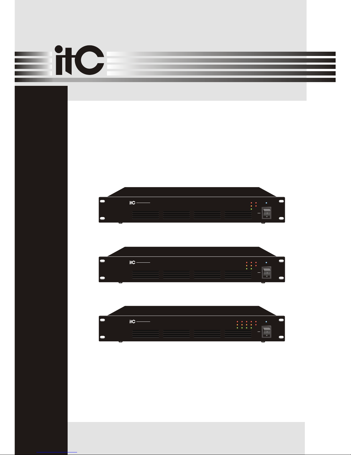
T-1D120R
CLASS-D AMPLIFIER
PROT
CLIP
SIG
STBY
24V DC
POWERCH1 CH2
OFF
ON
T-2D120R
CLASS-D AMPLIFIER
PROT
CLIP
SIG
STBY
24V DC
POWER
CH1
CH2 CH3 CH4
OFF
ON
T-4D120R
CLASS-D AMPLIFIER
PROT
CLIP
SIG
STBY
24V DC

1. SAFETY PRECAUTIONS ...............................................................................1
2. FEATURES....................................................................................................3
3. NOMENCLATURE AND FUNCTIONS
3.1 Front Panel T-1D120R-1D240R-1D350R-1D500R....................................................4
3 .2 Rear Panel T-1D120R-1D240R-1D350R-1D500R....................................................4
3.3 Front Panel T-2D120R-2D240R-2D350R-2D500R....................................................5
3.4 Rear Panel T-2D120R-2D240R-2D350R-2D500R....................................................5
3.5 Front Panel T-4D120R-4D240R-4D350R-4D500R....................................................6
3.6 Rear Panel T-4D120R-4D240R-4D350R-4D500R....................................................6
4. OPERATING INSTRUCTION...........................................................................7
5. WIRING INTRODUCTION ..............................................................................10
6. RS232 SERIAL PORT COMMUNICATION......................................................11
7. ............................................................................................12
. BLOCK DIAGRAM.......................................................................... .............14
9. OPERATING INSTRUCTIONS ...........
. FAULT DETECTION ........................
. ..........................
...........................
APPLICATIONS
................................................... 15
10 ................................................... 15
11 SPECIFICATIONS ................................................... 16
12. DIMENSIONAL DIAGRAM ........................................ 19
8
Be sure to read the instructions in this section carefully before use.
Make sure to observe the instructions in this manual as the conventions of safety symbols and messages
regarded as very important precautions are included.
We also recommend you keep this instruction manual handy for future reference.
Safety Symbol and Message Conventions
Safety symbols and messages described below are used in this manual to prevent bodily injury and property
damage which could result from mishandling. Before operating your product, read this manual first and
understand the safety symbols and messages so you are thoroughly aware of the potential safety
Indicates a potentially hazardous situation which, if mishandled, could
result in death or serious personal injury.
Indicates a potentially hazardous situation which, if mishandled, could
result in moderate or minor personal injury, and/or property damage.
Do not place cups, bowls, or other containers of
liquid or metallic objects on top of the unit. If they
accidentally spill into the unit, this may cause a
fire or electric shock.
Do not insert nor drop metallic objects or flammable
materials in the ventilation slots of the unit's cover,
as this may result in fire or electric shock.
When Installing the Unit When Installing the Unit
Should the following irregularity be found during
use, immediately switch off the power, disconnect
the power supply plug from the AC outlet and contact
y our nearest ITC dealer. Make no further attempt to
operate the unit in this condition as this may cause
fire or electric shock.
If you detect smoke or a strange smell coming
from the unit.
If water or any metallic object gets into the unit
If the unit falls, or the unit case breaks
If the power supply cord is damaged (exposure
of the core, disconnection, etc.)
If it is malfunctioning (no tone sounds.)
To prevent a fire or electric shock, never open nor
remove the unit case as there are high voltage
components inside the unit. Refer all servicing
to your nearest ITC dealer.
Do not expose the unit to rain or an environment
where it may be splashed by water or other liquids,
as doing so may result in fire or electric shock.
Use the unit only with the voltage specified on
the unit.Using a voltage higher than that which
is specified may result in fire or electric shock.
Do not cut,kink otherwise damage nor modify the
power supply cord. In addition, avoid using the
power cord in close proximity to heaters, and never
place heavy objects - including the unit itself - on
the power cord, as doing so may result in fire or
electric shock.
Be sure to replace the unit's terminal cover after
connection completion. Because high voltage
is applied to the speaker terminals, never touch
these terminals to avoid electric shock.
Be sure to ground to the safety ground (earth)
terminal to avoid electric shock. Never ground
to a gas pipe as a catastrophic disaster may result.
Avoid installing or mounting the unit in unstable
locations, such as on a rickety table or a slanted
surface. Doing so may result in the unit falling
down,causing personal injury and / or property
damage.
1. SAFETY PRECAUTIONS
1

SAFETY PRECAUTIONS
An all-pole mains switch with a contact separation of at least 3 mm in each pole shall be incorporated in
the electrical installation of the building.
Never plug in nor remove the power supply plug
with wet hands, as doing so may cause electric
shock.
When unplugging the power supply cord, be sure
to grasp the power supply plug; never pull on the
cord itself. Operating the unit with a damaged
power supply cord may cause a fire or electric
shock.
When moving the unit, be sure to remove its power
supply cord from the wall outlet. Moving the unit
with the power cord connected to the outlet may
cause damage to the power cord, resulting in fire or
electric shock. When removing the power cord, be
sure to hold its plug to pull.
Do not block the ventilation slots in the unit's cover.
Doing so may cause heat to build up inside the unit
and result in fire.
Avoid installing the unit in humid or dusty locations,
in locations exposed to the direct sunlight, near the
heaters, or in locations generating sooty smoke or
steam as doing otherwise may result in fire or
electric shock.
Do not place heavy objects on the unit as this may
cause it to fall or break which may result in personal
injury and/or property damage. In addition, the object
itself may fall off and cause injury and/or damage.
Make sure that the volume ontrol is set to minimum
position before power is switched on. Loud noise
produced at high volume when power is switched
on can impair hearing.
Do not operate the unit for an extended period of
time with the sound distorting. This is an indication
of a malfunction, which in turn can cause heat to
generate and result in a fire.
Contact your ITC dealer as to the cleaning. If
dust is allowed to accumulate in the unit over a
long period of time, a fire or damage to the unit
may result.
If dust accumulates on the power supply plug or in
the wall AC outlet, a fire may result. Clean it peri odically. In addition, insert the plug in the wall outlet
securely.
Switch off the power, and unplug the power supply
plug from the AC outlet for safety purposes when
cleaning or leaving the unit unused for 10 days or
more. Doing otherwise may cause a fire or electric
shock.
Due to product upgrades, while some of the
features and specification in the user manual
does not match the actual functions, sorry for
any inconvenience and thanks for your kind
understanding!
When Installing the Unit When Installing the Unit
2

3
1. High efficiency class D power amplifier;
2. Standard cabinet design(1.5U), humanized design, exquisite craft, all show high temperament;
3. Built-in active bandpass filter, filter out unwanted music signal effectively;
4. Balance signal input, 1/2/4x 120W, 240W, 350W, 500W power output;
5. Panel was regulating function independently;
6. Panel with signal, peak, protection, the power indicator LED;
7. With amplifier output, power standby control normal monitoring, power amplifier
standby cascade port;
8. Power amplifier with DC24V power supply port, charged pressure to adapt to the range
(21.6~ 26.5V DC) protection, avoid long-term supply for battery failure or damage of high voltage
equipment;
9. AC alternating current power supply pressure;
10.Power amplifier output: 100V voltage;
11.Electrical equipment electrical isolation, signal input and the power output isolation, in line with
the 3C, UL\ IEC60065 certification requirements;
12.Built-in short circuit, overload, high temperature protection.
13."STBY IN" sibling with "STBY thru", Normal when the port outputs high level, short of the port, the
amplifier standby protection panel "STBY" red indicator light; amplifier standby time and work
"STATE OUT" output 5V, when the amplifier output short circuit protection, the port output low.
14.When the channel "LINE IN" input signal, the corresponding port access VCA 10K adjustable
resistance, adjustable size of the input signal.
15.Supporting the RS232 ,communication protocol via RS-232 serial remote control of the amplifier
cascade standby computer, read amplifier status, can remotely adjust the signal sizes.
2.FEATURES

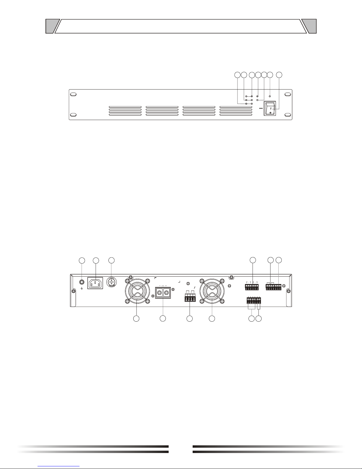
1. SIG
CH1 signal indicator
2. CLIP
CH1 clip indicator
3. PROT
CH1 protection indicator
8. Grounding terminal
9. AC power input
10. AC power fuse
11. Cooling fan
12. DC 24V power input
13. CH1 100V speaker output
4. Stby indicator
5. 24V DC indicator
6. Power indicator
7. POWER SWITCH
Up: turn on the power
Down: turn off the power
3.1 FRONT PANEL(T-1D120R-1D240R-1D350R-1D500R)
3.2 REAR PANEL(T-1D120R-1D240R-1D350R-1D500R)
4
3
11
16
8
21
6 7
4
5
9
10
12
13
11
14
15
14. Remote Standby, cascading standby
15. State output
16. Line input
17. Remote volume control;
External audio controller
18. RS232 port
17
POWER
CH1
OFF
ON
PROT
CLIP
SIG
STBY
24V DC
GND
STBYINGND
GND
STBY
THRU
STATE
OUT
BATT SUPPLY DC24V INPUT
CH1
100V SPEAKER OUTPUT
TRIGGER
CH1
LINE INPUT
VCA
CH1
RS-232
RX TX GND
18
1. SIG
CH1-CH2 s
CH1-CH2 clip
CH1-CH2
ignal indicator
2. CLIP
indicator
3. PROT
protection indicator
8. G
9. AC
use
11. Cooling fan
12.
rounding terminal
DC 24V power input
13. CH1 ~ CH2 100V speaker output
power input
10. AC power f
4. Stby indicator
5. 24V DC indicator
6. Power indicator
7. POWER SWITCH
Up: turn on the power
Down: turn off the power
3.3 FRONT PANEL(T-2D120R-2D240R-2D350R-2D500R)
3.4 REAR PANEL(T-2D120R-2D240R-2D350R-2D500R)
5
3
11
16
8
21
6 7
4
5
9
10
12
13
11
14
15
14. Remote Standby, cascading standby
15. State output
16. Line input
17. Remote volume control;
External audio controller
18. RS232 port
17
POWERCH1 CH2
OFF
ON
PROT
CLIP
SIG
STBY
24V DC
GND
STBYINGND
GND
STBY
THRU
STATE
OUT
CH1
CH2
100V SPEAKER OUTPUT
TRIGGER
CH1
CH2
LINE INPUT
VCA
CH1
CH2
BATT SUPPLY DC24V INPUT
RS-232
RX TX GND
18
 Loading...