

Page 1
®
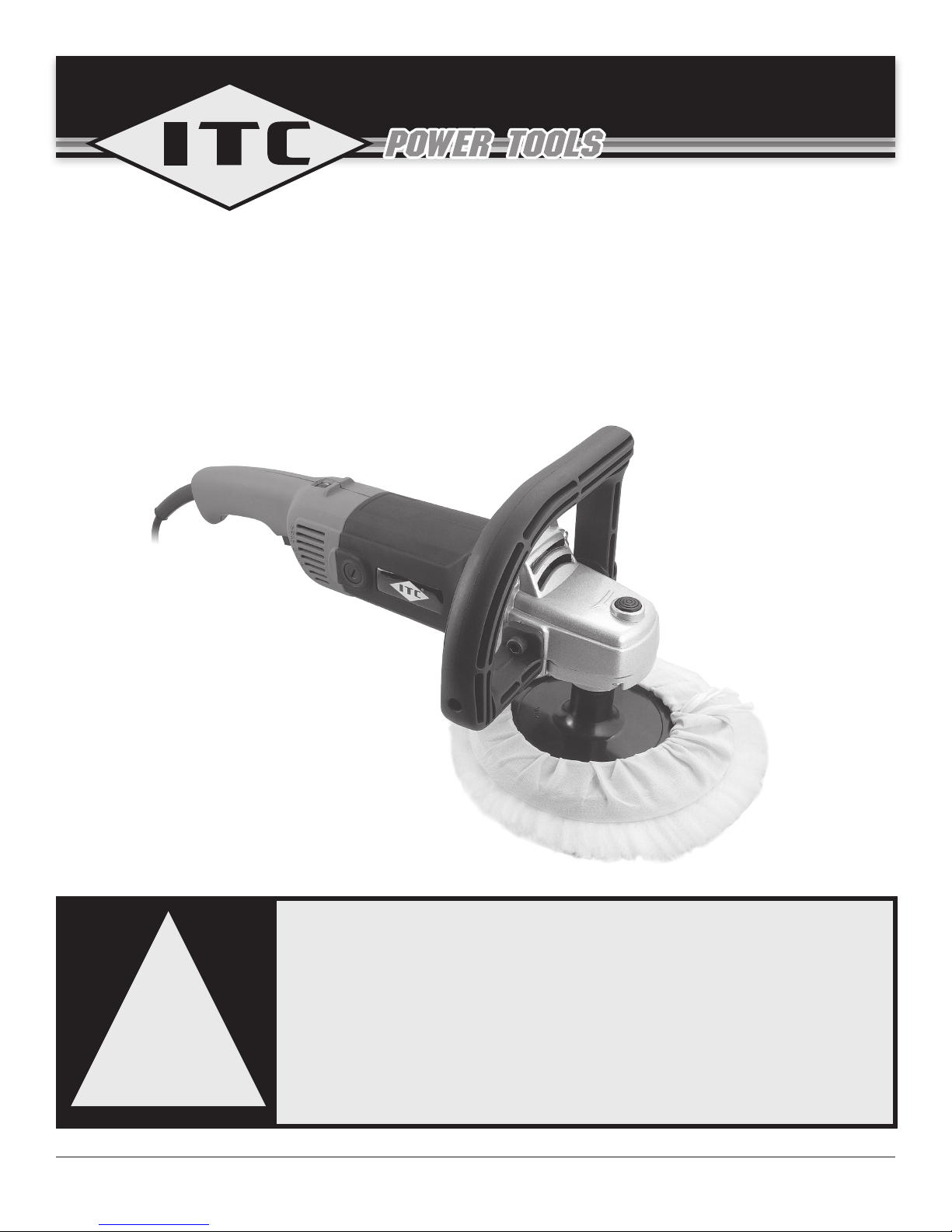
7" Variable Speed Polisher
Operator’s Manual (p.2)
Polisseuse de 7" à vitesse variable
Manual d’utilisateur (p.11)
PROD. NO. 011712
MOD. NO. SPT700
SAVE THIS MANUAL
You will need this manual for safety instructions, operating procedures, and
warranty. Put it and the original sales invoice in a safe, dry place for future
reference.
CONSERVEZ CE GUIDE
Vous aurez besoin de ce guide pour les instructions de sécurité, les
!
procédures d’utilisation et la garantie. Conservez-le dans un endroit sûr et
sec pour référence future.
www.itctoolscanada.com
Page 2

IMPORTANT SAFETY INSTRUCTIONS
WARNING! When using electric tools, machines or equipment, basic safety
precautions should always be followed to reduce the risk of re, electric
shock and personal injury.
READ ALL INSTRUCTIONS BEFORE USING THIS TOOL
1. KNOW YOUR POWER TOOL. Read and understand this manual and any
label attached to the tool. Learn the applications, limitations, and potential
hazards associated with its use.
2. KEEP WORK AREA CLEAN. Cluttered areas invite injuries.
ENGLISHFRANÇAIS
3. CONSIDER WORK AREA ENVIRONMENT. Don’t use power tools in damp,
wet, or poorly lit locations. Don’t expose your tool to rain. Keep the work
area well lit. Don’t use tools in the presence of ammable gases, liquids, and
potentially explosive dust. Keep a suitable re extinguisher handy and know
how to use it.
4. GUARD AGAINST ELECTRIC SHOCK. Prevent body contact with grounded
surfaces: pipes, radiators, ranges, and refrigerator enclosures. When drilling
into walls, oors, or wherever “live” electrical wires may be encountered, try to
ascertain whether there is a danger of shock. Even so, DO NOT TOUCH THE
CHUCK OR ANY METAL PARTS OF THE DRILL. Hold the tool only by the
plastic handle to prevent electric shock in case you hit a live wire.
5. KEEP CHILDREN AND PETS AWAY. All children should be kept away from
the work area. Don’t let them handle machines, tools or extension cords.
6. DON’T FORCE THE TOOL. It will do the job better and more safely, as well as
give a longer life and better service, at the rate for which it was intended.
7. USE THE RIGHT TOOL. Don’t force a small tool or attachment to do the work
of a larger industrial tool. Don’t use a tool for a purpose for which it was not
intended.
8. DRESS PROPERLY. Don’t wear loose clothing or jewelry: they can be caught
in moving parts. Protective, non-electrically conductive gloves and non-skid
footwear are recommended when working. Wear protective hair covering to
contain long hair and keep it from harm.
9. USE EYE PROTECTION at all times while using this machine. Wear ANSI-
approved safety glasses. Use a full face mask if the work you’re doing
produces metal lings, dust or wood chips.
10. USE HEARING PROTECTION, especially during periods of extended use.
11. FOOTWEAR Where there is a risk of heavy objects hitting your feet or of
slipping on wet or greasy oors, wear non-slip safety footwear.
12. HEAD GEAR Where there is risk of falling objects or of hitting your head on
protruding obstructios at a low level, wear a hard hat.
13. BREATHING PROTECTION. Wear a clean dust mask if the work involves
creating a lot of ne or coarse dust Be sure that you are protected from the
dust produced by your use of this tool. Dust masks must be equipped with
lters appropriate for the material.
14. DO NOT ABUSE THE CORD. Never carry your tool by the cord or pull on the
cord to unplug it. Protect the cord from potential sources of damage: heat,
oil and solvents, sharp edges, or moving parts. Replace damaged cords
immediately.
15. WHEN WORKING OUTDOORS, USE AN OUTDOOR-RATED EXTENSION
CORD. An extension cord rated for outdoor use must be marked “W-A” or “W”.
16. DO NOT EXPOSE ELECTRICAL POWER TOOLS TO MOISTURE. Rain or
wet conditions can cause water to enter the tool and lead to electric shock.
17. EXTENSION CABLES AND REELS. Do not use a 2-wire extension cord
for tools which have a ground prong on the plug. A grounded plug requires a
3-wire extension cord capable of carrying the grounding to earth. When using
extension cords on a reel, always unwind the cord from the reel completely or
dangerous heating and tool damage may take place.
2
Page 3

IMPORTANT SAFETY INSTRUCTIONS
18. ENSURE THE EXTENSION CORD YOU USE IS OF SUFFICIENT GAUGE
FOR ITS LENGTH.
RECOMMENDED MINIMUM WIRE GAUGE FOR EXTENSION CORDS
Amps
from Tool
Nameplate
0 - 5 amps 16 ga. 16 ga. 16 ga. 14 ga. 12 ga. 12 ga.
5.1 - 8 amps 16 ga. 16 ga. 14 ga. 12 ga. 10 ga. Do Not
8.1 - 12 amps 14 ga. 14 ga. 12 ga. 10 ga. Do Not
12.1 - 15 amps 12 ga. 12 ga. 10 ga. 10 ga. Do Not
15.1 - 20 amps 10 ga. 10 ga. 10 ga. Do Not
25' long 50' long 75' long 100'
long
Use
150'
long
Use
Use
Do Not
Use
200'
long
Use
Do Not
Use
Do Not
Use
Do Not
Use
ENGLISH
19. DON’T OVERREACH. Keep proper footing and balance at all times. Do not
reach over or across machines which are running.
20. MAINTAIN TOOLS WITH CARE. Keep tools sharp and clean for better and
safer performance. Follow instructions for lubricating and safe performance.
Follow instructions for lubricating and changing accessories. Keep handles dry,
clean and free from oil and grease.
21. DISCONNNECT THE TOOL FROM POWER when not in use, before
servicing,making any adjustments, or changing accessories. Changing
attachments or accessories can be dangerous if the tool accidentally starts.
22. AVOID UNINTENTIONAL STARTING. Don’t carry tool with a nger on or near
the trigger. Be sure the On/Off switch is in the Off position when plugging the
tool into the power supply.
23. STAY ALERT. Watch what you are doing and use common sense. Don’t
operate any tool when you are tired.
24. STORE IDLE EQUIPMENT. Store equipment in a dry area to inhibit rust.
Equipment also should be in a high location or locked up to keep out of reach
of children.
25. SECURE WORK. Use clamps or a vise to hold the work if possible. It’s safer
than using your hands and it frees both hands to operate the tool.
26. REMOVE ADJUSTING KEYS AND WRENCHES. Make it a habit to check that
keys and adjusting wrenches are removed from any rotating tool before using.
27. MODIFYING A POWER TOOL in any way or using any attachment other than
those recommended in this manual could result in damage to the tool and
injury to the operator.
28. CHECK FOR DAMAGED PARTS. Before using this tool, any part that is
damaged should be carefully checked to determine that it will operate properly
and perform its intended function. Check for mis-alignment or binding of
moving parts, breakage of parts and mountings and for other conditions
that may affect tool operation. Check bits to make sure they are sharp and
not chipped. Inspect screws and tighten any that are loose. Any part that is
damaged should be properly repaired or replaced by an authorized service
center unless otherwise indicated elsewhere in the instruction manual. Have
defective switches replaced by an authorized service center. Don’t use the tool
if switch does not turn on and off properly.
29. REPLACEMENT PARTS. When servicing, use only identical replacement
parts.
FRANÇAIS
3
Page 4

ADDITIONAL SAFETY INSTRUCTIONS
= When the tool is in operation, keep hands away from the polishing area.
= Always hold the tool with both hands.
= The polishing pad will not come to an immediate stop when the tool is turned
off. Exercise caution.
= Do not put the tool down after use until the polishing pad has stopped rotation
completely.
= Use only polishing pads that are rated for a maximum speed of 3,000 rpm or
greater.
ENGLISHFRANÇAIS
= Use only polishing pads with the correct bore to match the spindle size of the
tool.
= Keep the power cord well away from the polishing area during use. The cord
can be picked up by the bonnet and wrap around the spindle quickly. Take care
to position the cord in such a way as to preclude it being caught on something
while the tool is in use.
WARNING! The warnings, cautions, and instructions detailed in this manual cannot cover all
possible conditions and situations that occur. It must be understood by the operator that
COMMON SENSE AND CAUTION ARE FACTORS that cannot be built into this product, but
MUST BE SUPPLIED BY THE OPERATOR.
SPECIFICATIONS
BUFFER / ANGLE POLISHER
= Electronic variable speed:900-3,000 rpm, no-load speed
= 120 volts, 60 Hz, 10 amps
= 5/8" x 11 tpi spindle
= 7" diameter backing pad
= Tool weight: 6.6 lb.
= Easy to set thumb wheel speed adjustment
= D-shaped auxiliary handle allows many comfortable hand positions
= Trigger with lock-on button
= Metal gear housing
CONTENTS AND ASSEMBLY
CONTENTS
= Polisher unit
= D-handle
= Polishing backing pad
= Hex wrench
= 2 Hex socket head screws
= Polishing bonnet
= 7" diameterP120 adhesive sand paper disc
ASSEMBLY
WARNING! Be sure the tool is not connected to the power supply before
attempting assembly.
HANDLE
1. Position the D-handle (D, g.1) on the metal gear housing at the front of the
tool.
2. Thread the two hex socket head screws (H, g.1) into the threaded holes on
either side of the tool.
3. Using the supplied hex wrench, tighten the screws in place.
4
Page 5
CONTENTS AND ASSEMBLY
BACKING PAD
1. Screw the rubber backing pad (A, g.1) onto the spindle in a clockwise
direction.
2. Tighten it in place by holding in the Spindle lock button while turning the pad
until it will turn no further.
SAND PAPER
Your tool comes with one sample piece of 7" diameter 120 grit adhesive-backed
sanding disc.
1. Peel the backing off the sand paper disc. Align it and press it to stick it directly
to the bottom surface of the sandng pad.
2. When you wish to change paper, or use the tool for bufng, peel the sandpaper
off the backing pad.
3. Take care to check the paper sanding disc for damage frequently. A torn or
worn-through sanding disc can allow the bottom surface of the backing pad to
be damaged.
BONNET
1. Remove the sand paper, if any, from the backing pad.
2. Slip the polishing bonnet over the backing pad.
3. Be sure it is tight.
4. Connect the tool to power and run it for a minute off the work surface to be
sure the bonnet is secure.
ENGLISH
FRANÇAIS
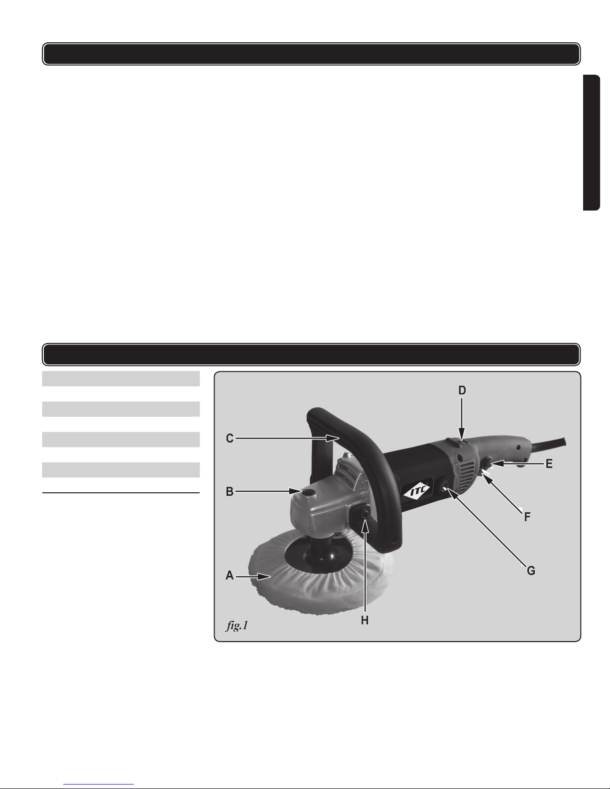
A Backing pad
B Spindle lock button
C Auxiliary D-handle
D Speed control wheel
E Trigger lock-on button
F Trigger
G Brush holder cap
H Handle mounting screw
FUNCTIONAL DESCRIPTION
5
Page 6

OPERATING PROCEDURES
WARNING!
= Ensure that you have read and understood all the Safety Instructions at the
beginning of this manual before operating this tool.
= Ensure the on/off switch is NOT locked in the on position before connecting to
the power supply.
1. Hold the tool rmly off the work surface with one hand on the rear hand grip
and the other on the forward d-handle.
2. With your thumb, rotate speed control wheel (D, g.1) to select the
ENGLISHFRANÇAIS
approximate setting desired.
3. With your index nger, squeeze the trigger (F, g.1) and hold it in the On
position.
4. When the tool is running at the correct, speed, lower it gently onto the surface.
5. Lift the tool carefully off the surface before turning it off.
= You can lock the trigger in the On position by pressing the Trigger lock-on
button (E, g.1) with your thumb while holding the trigger in. You can now
release the trigger and the tool will continue to run. This helps prevent fatigue
during jobs of long duration.
= The trigger lock can be released if desired by again pushing in the trigger.
= The spindle rotation speed can be varied from 600 to 3,000 rpm by rotating
the speed control wheel. Higher speeds are represented on the wheel by the
higher numbers, generally for sanding. Lower speeds are produced when the
wheel is turned to expose the lower numbers. It is these lower speeds that are
most desirable for polishing. Bufng larger areas allows you to move the tool
more widely and continually, and this might also allow you to run the machine
at a somewhat higher rotation speed. Normally, high rotation speeds can lead
to accidentally burning through the paint on a surface.
MAINTENANCE
WARNING! Before attempting any maintenance, be sure the tool is disconnected
from the power supply.
= Keep the tool clean using a soft damp (not wet) cloth. Do not use solvents on
the plastic parts. Do not use abrasives.
= Check that external screws are tight.
= Clean the ventilation slots regularly with a jet of air to prevent the tool
overheating.
= Lubrication is not necessary. After long use, have an authorized service center
maintain and lubricate the tool.
= Any internal maintenance on this tool must be carried out by a qualied
technician.
6
Page 7
ITEM NODESCRIPTION
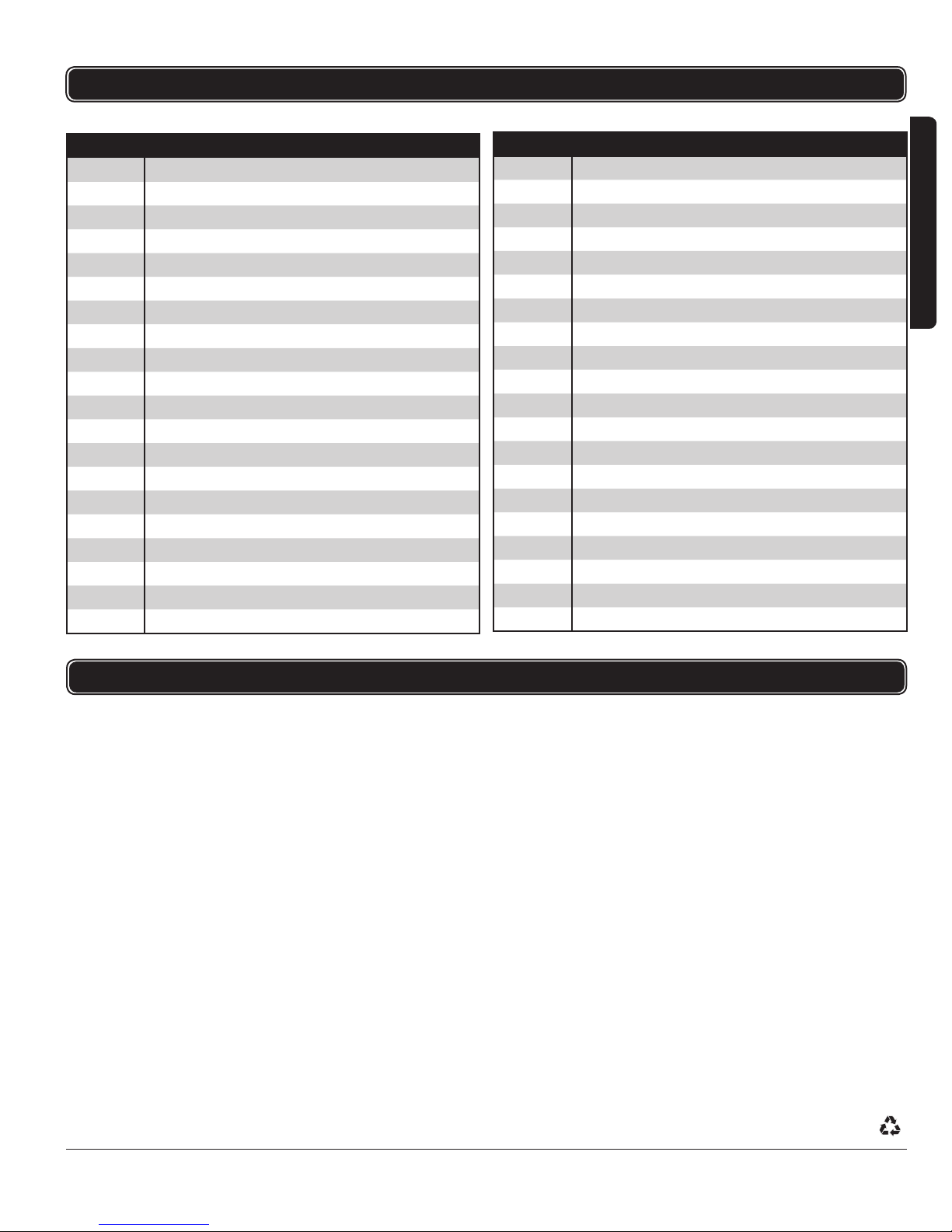
1 Main spindle
2 M5 x 14 philips screw
3 M5 spring washer
4 Bearing block
5 6201 bearing
6 32 mm check ring
7 607 bearing
8 Gear
9 12 mm check ring
10 St5 x 30 philips screw
11 Reduction gear box
12 5 mm check ring
13 Spring
14 Lock pin
15 12 mm check ring
16 6201 bearing
17 Bearing pressure plate
18 5 mm circlip
19 M5 x 10 philips screw
20 Rotor
PARTS LIST
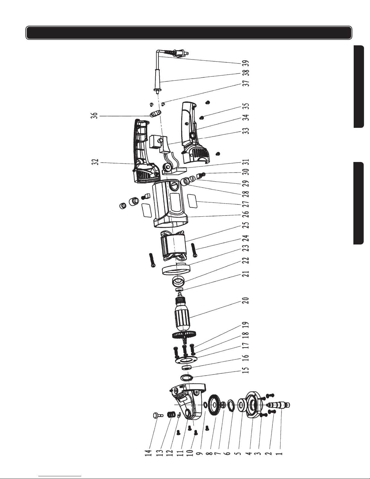
Please refer to the schematic drawing on page 15.
ITEM NODESCRIPTION
21 607 bearing
22 Bearing sleeve
23 Orientation circle
24 St4 x 65 philips screw
25 Stator
26 Housing
27 Nameplate
28 Brush holder
29 Brush cover
30 Brush
31 Activator
32 Right handle
33 Switch
34 Left handle
35 St4 x 22 philips screw
36 Cord clamp
37 St4 x 14 philips screw
38 Cord protector
39 Plug and cord assembly
40 Front handle
ENGLISH
FRANÇAIS
WARRANTY
ITC TOOLS AND EQUIPMENT (ITC) WARRANTY POLICY
All ITC branded products are guaranteed against defects in
workmanship and materials, when the product is used for
the purpose for which it was designed. Any ITC product that
fails during normal use and within the specied warranty
period for that product will be repaired or replaced at ITC’s
discretion.
ITC product warranties apply to ITC products purchased
new from an authorized ITC distributor
ITC product warranties are extended to the original retail
purchaser only.
See specic product warranty statements for more
information and limitations.
This warranty is void if there is evidence of misuse, abuse,
alterations, or normal wear and tear. Normal wear and
tear of moving parts can be repaired by purchasing the
appropriate ITC replacement part.
Go towww.itctoolscanada.com click on ITC Power Tools
Warranty for a list of authorized warranty repair centers.
®Registered trademark of JET Equipment & Tools. JET makes every effort to ensure that the information in this manual is current and accurate, however cannot accept responsibility and or liability for any loss or damage suffered as
a result of information contained herein. Products may be discontinued and specifications may be subject to change without notice. The trademarks, logos and service marks printed in this manual are registered and unregistered
Trademarks of this company and no trademark license either expressed or implied is granted by JET. Trademarks printed in this manual can not be used without prior written permission of JET.
www.itctoolscanada.com
No claim for indirect, incidental, or consequential, damages
of any type will be considered including loss time or wages,
loss of production. All products are sold with this specic
understanding.
Product for which there is a warranty claim must be
returned, freight prepaid to an authorized ITC distributor,
or in the case of machinery and hydraulic equipment, to
an authorized ITC warranty repair center. All returns must
include proof of purchase and an explanation of the defect
or failure.
2 Year Warranty
These products are designed for use in DIY (do-it-yourself),
light or intermittent duty, applications. They are not
intended for use in production, industrial or continual use
applications.
This warranty does not extend to normal wear or
consumable parts such as brad and staple gun driver
blades, grinding discs, saw blades, driver bits, electrical
motor brushes, worn cords, etc.
7
Page 8

IMPORTANTE DIRECTIVES DE SÉCURITÉ
AVERTISSEMENT : Durant l’usage des outils électriques, des machines et de
l’équipement, des précautions de sécurité de base devraient toujours être
observées pour réduire le risque d’incendie, de choc électrique et de blessures
corporelles.
LIRE TOUTES LES INSTRUCTIONS AVANT D’UTILISER CET OUTIL.
1. CONNAISSER VOTRE OUTIL, liser et comprener votre manuel. Les
applications, limitations et problemes potentiels associé a son utilisation.
2. CONSERVEZ L’AIRE DE TRAVAIL PROPRE. Le désordre invite les
ENGLISHFRANÇAIS
blessures.
3. SOYEZ CONSCIENT DE VOTRE ENVIRONNEMENT DE TRAVAIL. Ne
pas utiliser cet outil quand il y a des vapeurs d’essence ou tout autre liquide
inammable. Toujours avoir un instincteur fonctionnelle à porté de main.
4. PRÉVENEZ LES CHOCS ÉLECTRIQUES. Éviter le contact de votre
corps avec les surfaces mises à terre : tuyaux, radiateurs, cuisinières et
réfrigérateurs. Si votre corps est mis à la terre, le risque de choc électrique
est augmenté. Si vous effectuez des travaux dans les secteurs où des ls
électriques sous tension pourraient être touchés, tentez de déterminer s’il y a
un risque de choc électrique. Mais en toute circonstance, NE PAS TOUCHER
AUNE PARTIE MÉTALLIQUE DE L’OUTIL durant son usage. Toujours tenir
l’outil par la poignée en plastique pour prévenir les chocs électriques en cas de
contact avec un l sous tension.
5. TENIR LES ENFANTS ET PETITS ANIMAUX ELOIGNÉS. Tous les enfants
doivent être tenus à l’écart de l’aire de travail. Ne leur permettez pas de
toucher les machines, les outils ou les cordes de rallonge.
6. NE PAS FORCER L’OUTIL. Il fera un meilleur travail, de manière plus
sécuritaire, au rythme pour lequel il est conçu.
7. UTILISEZ L’OUTIL APPROPRIÉ. Ne pas forcer un petit outil ou un accessoire
à faire le travail d’un outil industriel plus gros. Ne pas utiliser un outil à une n
pour laquelle il n’a pas été conçu.
8. HABILLEZ-VOUS DE MANIÈRE APPROPRIÉE. Ne pas porter de vêtement
ample ou de bijoux. Ils peuvent être attrapés par les pièces mobiles. Des
gants de protection à l’épreuve de la conductivité électrique et des souliers
antidérapants sont recommandés durant le travail. Portez un couvre-tête de
protection pour recouvrir les cheveux longs et prévenir les emmêlements.
9. UTILISER DES VERRES DE PROTECTION, En tout temps lors de l’utilisation
porter des verre de protection approuvé par ANSI. Utilisez un masque qui
recouvre le visage tout entier si le travail que vous effectuez produit de la
limaille métallique, de la poussière ou des éclats de bois.
10. TILISE DES BOUCHONS POUR L’OUIE, spécialement quand utilisé pour une
longue période.
11. SOULIER DE PROTECTION, Quand il y a risque qu’un objet lourd puisse
tomber ou si le sol est mouillé porter des semelles anti-dérappantes.
12. ASQUE DE PROTECTION, si il y a danger pour cause d’objet plus bas que la
normale, obstruant, ou qui pourrait tomber porter un casque de construction.
13. PROTECTION RESPIRATOIRE, Porter un masque propre.
14. NE PAS ABUSER LE CORDON. Ne jamais transporter votre outil par le
cordon ou tirer sur le cordon pour le débrancher. Protégez le cordon des
sources potentielles de dommage : La chaleur, l’huile et les solvants, les
rebords aiguisés ou les pièces mobiles. Remplacez les cordons endommagés
immédiatement.
15. POUR LE TRAVAIL À L’EXTÉRIEUR, TOUJOURS UTILISER UNE CORDE
DE RALLONGE HOMOLOGUÉE POUR L’USAGE À L’EXTÉRIEUR. Une
corde de rallonge homologuée pour usage à l’extérieur doit porter la marque
« W-A » ou « W ».
16. NE PAS EXPOSER LES OUTILS ÉLECTRIQUES À L’HUMIDITÉ. La pluie ou
les conditions humides peuvent causer l’inltration d’eau dans l’outil et il peut.
8
Page 9

IMPORTANTE DIRECTIVES DE SÉCURITÉ
17. CORDON DE RALLONGE (Extentions) Ne pas utiliser une rallonge de 2 ls
pour les outils qui ont une prise de mise à terre. La mise à terre exige une
rallonge à trois (3) ls avec prise de mies à terre. Quand vous utiliser une
rallonge remiser sur une roue de remisage, toujours enlever la rallonge pour
ne pas qu’elle surchauffe et endommage l’outil.
18. ASSUREZ-VOUS QUE LA CORDE DE RALLONGE QUE VOUS UTILISEZ
EST DE CALIBRE SUFFISANT POUR SA LONGUEUR.
Calibre minimum recommandé pour les cordons de rallonge
Indice
d’intensité
(ampère)
0 - 5 amp. cal. 16. cal. 16 cal. 16 cal. 14 cal. 12 cal. 12
5.1 - 8 amp. cal. 16 cal. 16 cal. 14 cal. 12 cal. 10 Ne pas
8.1 - 12 amp. cal. 14 cal. 14 cal. 12 cal. 10 Ne pas
12.1 - 15 amp. cal. 12 cal. 12 cal. 10 cal. 10 Ne pas
15.1 - 20 amp. cal. 10 cal. 10 cal. 10 Ne pas
Longueur de
7,6 m (25 pi)
Longueur
de 15,2 m
(50 pi)
Longueur
de 22,9 m
(75 pi)
Longueur
de 30,4 m
(100 pi)
utiliser
Longueur
de 45,7 m
(150 pi)
utiliser
utiliser
Ne pas
utiliser
Longueur
de 60,9 m
(200 pi)
utiliser
Ne pas
utiliser
Ne pas
utiliser
Ne pas
utiliser
ENGLISH
FRANÇAIS
19. NE PAS VOUS ÉTIREZ. Conservez vos pieds sur le sol et maintenez votre
équilibre en tout temps. Ne vous avancez pas au-dessus ou à travers les
machines qui sont en mode de fonctionnement.
20. MAINTENEZ L’OUTIL EN BON ÉTAT. Conservez l’outil eflé et propre pour
une meilleure performance et plus de sécurité. Observez les instructions
pour la lubrication et la performance sécuritaire. Respectez les directives
de lubrication et de changement des accessoires. Conservez les poignées
propres, sèches et libres d’huile et de graisse.
21. DÉBRANCHER TOUJOURS L’OUTIL QUAND IL N’EST PAS UTILISÉ,
quand vous devez faire des ajustements ou changer des accessoires. Les
changements de pièce ou d’accessoire peuvent être dangereux si l’outil peut
être activé accidentellement.
22. ÉVITEZ LA MISE EN MARCHE ACCIDENTELLE. Ne pas transporter l’outil
avec le doigts sur le commutateur. Assurez-vous que l’interrupteur est à la
position « ARRÊT » avant de brancher l’outil.
23. SOYEZ ALERTE. Surveillez vos mouvements et utilisez le sens commun.
N’utilisez pas un outil quand vous êtes fatigué.
24. REMISEZ L’ÉQUIPEMENT QUI N’EST PAS UTILISÉ. Remisez l’équipement
dans un endroit sec pour empêcher la rouille. L’équipement devrait aussi
être remisé dans un endroit haut ou sous clé, hors d’atteinte de la portée des
enfants.
25. FIXEZ SOLIDEMENT LA PIÈCE DE TRAVAIL. Utilisez des pinces ou un étau
pour tenir la pièce de travail. C’est beaucoup plus sécuritaire que l’usage de
vos mains et ceci libère vos deux mains pour contrôler l’outil.
26. ENLEVER LA CLÉ D’AJUSTEMENT ET CLÉ. Prenez l’habitude de toujours
vérier si vous n’avez pas laisser la clé d’ajustement avant l’utillisation.
27. MODIFICATION DE L’OUTIL. Ne jamais modier ou utiliser des accessoires
autres que ceux spécie.s dans le manuel d’instruction, il pourrait enrésulter
des blessures et vous pourriez endomager l’outil.
9
Page 10

IMPORTANTE DIRECTIVES DE SÉCURITÉ
28. EXAMINEZ POUR DES PIÈCES ENDOMMAGÉES. Avant d’utiliser cet outil,
toute pièce qui est endommagée devrait être soigneusement examinée pour
s’assurer qu’elle fonctionnera adéquatement et qu’elle remplira sa fonction.
Vériez pour l’alignement et le coincement des pièces mobiles, le bris des
pièces, les montures et toutes autres conditions qui pourraient affecter dans
lesonfonctionnement. Examinez les vis et resserrez celles qui sont relâchées.
Toute pièce qui est endommagée devrait être correctement réparée ou
remplacée par le centre de service autorisé, sauf si autrement indiqué ailleurs
manuel de l’utilisateur. Les interrupteurs défectueux doivent être remplacés
par un centre de service autorisé. Ne pas utiliser l’outil si l’interrupteur ne
ENGLISHFRANÇAIS
fonctionne pas correctement.
29. PIÈCES DE RECHANGE. Pour le service, n’utilisez que des pièces de
rechange identiques seulement.
ADDITIONAL SAFETY INSTRUCTIONS
= Quand l’outil est en fonction, gardez les mains loin de la zone de polissage
toujours prendre l’outil avec les deux mains.
= Le coussin de polissage ne viendra pas à un arrêt immédiat quand l’outil est
arrêté. Soyez prudent.
= Ne mettez pas l’outil par terre avant que le coussin de polissage soit
completement arrêter.
= Utilisez seulement des coussin de polissage fait pour des vitesses de 3000rpm
ou plus.
= Utilisez seulement des coussin de polissage avec la bonne grosseur d’arbre
pour l’outil.
= Gardez la corde d’extension loin de la zone de polissage pendant l’utilisation.
La corde peut être prise et s’enrouler autour de l’axe rapidement. Faites
attention pour placer la corde de façon à l’éloigner de l’arbre tandis que l’outil
est en service.
AVERTISSEMENT! Les avertissements, les attentions, et les instructions détaillées dans
ce manuel ne peuvent pas couvrir toutes les conditions et situations possibles qui se
produisent. L’opérateur doit comprendre que le BON SENS ET L’ATTENTION SONT
DES FACTEURS qui ne peuvent pas être établis dans ce produit, mais DOIVENT ÊTRE
FOURNIS PAR L’OPÉRATEUR.
SPÉCIFICATIONS
Polisseur à angle
= Vitesse variable électronique : 900-3,000 tr/min, sans charge
= 120 V, 60 Hz, 10 A
= Arbre 5/8 po x 11 tpi
= Diamètre de coussin de 7 po
= Poids de l’outil : 6,6 lb.
= Ajustement de la vitesse variable au pouce
= Poignée auxiliaire en D facile et confortable
= Gàchette avec bouton barré
= Engrenage en metal
10
Page 11

CONTENU ET ASSEMBLAGE
CONTENU
= Polisseuse
= Poignée en D
= Coussin de polissage
= Clé Hex
= 2 vis à tête Hex
= Bonnet de polissage
= Papier sablé P120 de 7po de diamètre
ASSEMBLAGE
AVERTISSEMENT! Soyez certain que l’outil n’est pas branché avant
l’assemblage
Poignée
1. Positionnez la poigné en D (D, g.1) sur la tête de l’outil
2. Vissez manuellement les vis à tête Hex (H, g.1) dans les trous de chaque
côtés de l’outil.
3. Utilisez la clé Hex pouir serrer correctement.
Coussin d’appui
1. Vissez le coussin d’appui (A, g.1) dans l’arbre dans le sens Horaire.
2. Serrez-le en place en maintenant le bouton de blocage de l’arbre (B, g.1) tout
en tournant le coussin jusqu’à ce qu’il ne tourne plus.
ENGLISH
FRANÇAIS
Papier sablé
Votre outil vient avec une feuille de papier sablé ronde de 7po de diamètre P120.
1. Enlevez la feuille d’en arrière de la feuille de papier sablé. Alignez-la et
pressez pour qu’elle colle directement sur le coussin d’appui.
2. Quand vous voulez utiliser l’outil pour polir ou si vous vouler changer le
papier sablé, retirer-le tout simplement.
3. Soyez attentif à la condition de papier sablé, un papier sablé endommagé ou
sur-utilisé peut engendrer une détérioration du coussin d’appui.
Bonnet
1. Enlevez le papier sablé (sìl y en a) du Coussin d’appui.
2. Glissez le bonnet par dessus le coussin d’appui.
3. Soyez certain quìl est maintenu en place fermement.
4. Branchez l’outil et faites-le marcher durant un instant pour conrmer que le
bonnet est bien en place.
11
Page 12
DESCRIPTION FONCTIONNELLE
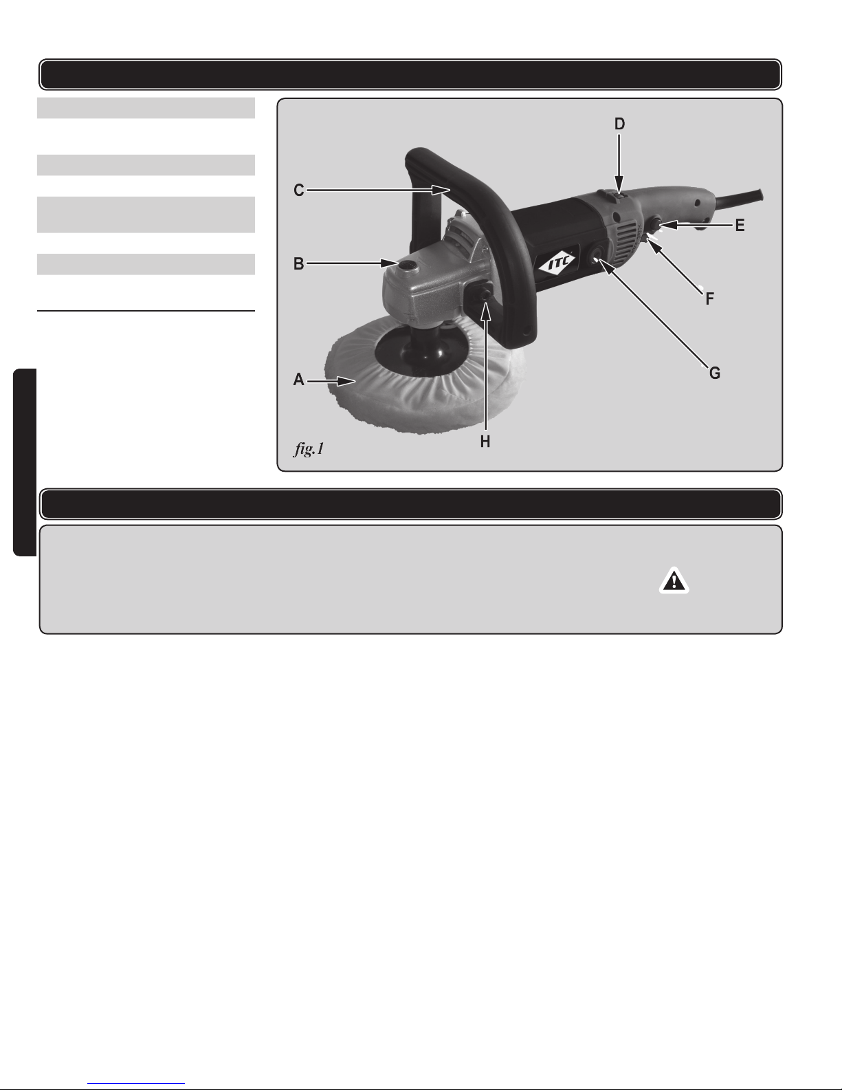
A Coussin d’appui
B Bouton de blocage de
l’arbre
C Poignée auxiliaire en D
D Contrôle de vitesse
E Bouton de blocage de la
gâchette
ENGLISHFRANÇAIS
F Gâchette
G Capuchon de brosse
H Vis de montage de la
poignée
PROCÉDURES D’UTILISATION
AVERTISSEMENT !
= Assurez-vous que vous avez lu et compris toutes les instructions de sûreté
au début de ce manuel avant d’actionner cet outil.
= Assurez que le commutateur “Marche/Arrêt” n’est pas fermé à clef dans la
position de fonctionnement avant de le brancher à l’alimentation de courant.
1. Tenez l’outil fermement loin de la surface de travail avec une main sur la
poignée arrière et l’autre sur la poignée avant. 2. Avec votre pouce, tournez la
roue de commande de vitesse (D, g.1) pour choisir la vitesse désiré.
3. Avec votre index, serrez la gâchette (F, g.1) et tenez-la dans en position
engagéet.
4. Quand l’outil fonctionne à la bonne vitesse, abaissez-le doucement sur la
surface.
5. Soulevez l’outil soigneusement loin de la surface avant de l’arrêter.
= Vous pouvez barrer la gâchette dans la position de fonctionnement en
appuyant sur le bouton de verrouillage de déclenchement (E, g.1) avec votre
pouce tout en tenant la gâchette. Vous pouvez maintenant libérer la gâchette
et l’outil continuera à fonctionner. Ceci aide à diminuer la fatigue pendant les
travaux de longue durée.
= La serrure de déclenchement peut être libérée si désiré en enfonçant encore la
gâchette.
12
Page 13
PROCÉDURES D’UTILISATION
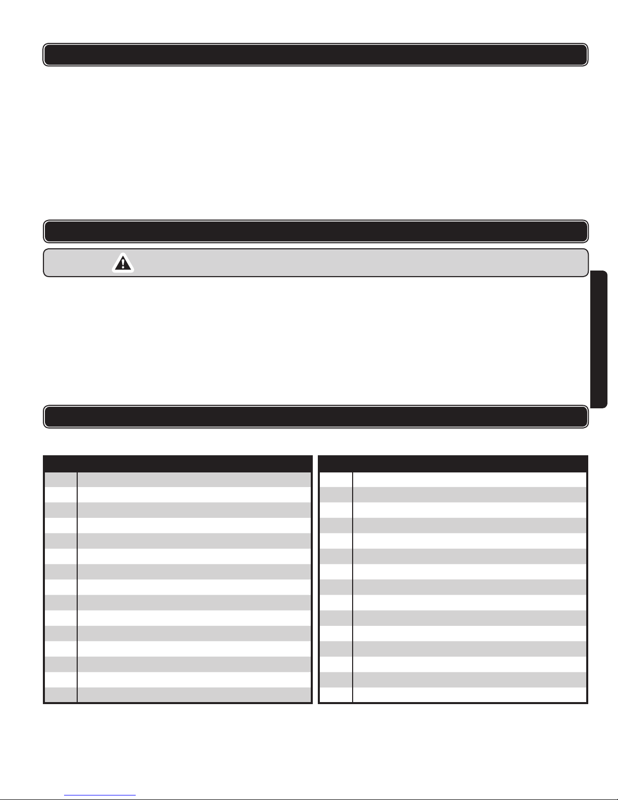
= La vitesse de rotation d’axe peut être variée de 600 à 3,000 t/mn en
tournant la roue de commande de vitesse. Des vitesses plus élevées sont
représentées sur la roue par des nombres plus élevés, généralement pour le
ponçage. Des vitesses inférieures sont produites quand la roue est tournée
pour exposer les nombres moins élevés. Ce sont des vitesses inférieures qui
sont les plus souhaitables pour le polissage. Le polissage plus grands des
secteurs vous permet de déplacer l’outil plus largement et continuellement,
et ceci pourrait également vous permettre de faire tourner la machine à une
vitesse de rotation légèrement plus élevée. Normalement, les vitesses de
rotation élevées peuvent mener accidentellement à une brûlure de la peinture
sur une surface.
ENTRETIEN
AVERTISSEMENT! Avant d’essayer n’importe quel entretien, soyez sûr que
l’outil est débranché du courant.
ENGLISH
o.
N
1 Arbre principal
2 Vis M5 X 14
3 Rondelle à ressort M5
4 Plaque de roulement
5 Roulement 6201
6 Barrure en ‘C’ 32 mm
7 Roulement 607
8 Engrenage
9 Barrure en ‘C’ 12 mm
10 Vis ST5 X 30
11 Boitier d’engranage
12 Barrure en ‘C’ 5 mm
13 Rondelle
14 Goupille de verrou
15 Barrure en ‘C’ 12 mm
DESCRIPTION
= Gardez l’outil propre utilisant un doux tissu humide. N’employez pas de
solvants sur les pièces en plastique. N’employez pas d’abrasifs.
= Assurez-vous que les vis externes sont serrées.
= Nettoyez les fentes de ventilation régulièrement avec un gicleur d’air pour
empêcher l’outil de surchauffer.
= La lubrication n’est pas nécessaire. Après une longue utilisation, faites
lubrier chez un centre de service autorisé
= N’importe quel entretien interne sur cet outil doit être effectué par un
technicien qualié.
LISTE DES PIÈCES
S’il vous plaît, référer au dessin schématique à la page 15.
o.
N
16 Roulement 6201
17 Plaque de pression
18 Anneau de retenu (5 mm)
19 Vis M5 X 10
20 Rotor
21 Roulement 607
22 Manchon de roulement
23 Couvercle d’orientation du stator
24 Vis ST4 X 65
25 Stator
26 Boitier du moteur
27 Plaque d’identité
28 Porte-balai
29 Couvercle du balai
30 Balai de charbon
DESCRIPTION
FRANÇAIS
13
Page 14

LISTE DES PIÈCES
S’il vous plaît, référer au dessin schématique à la page 15.
o.
N
DESCRIPTION
31 Capacitor
32 Poignée (droite)
33 Commutateur
34 Poignée (gauche)
35 Vis ST4 X 22
ENGLISHFRANÇAIS
GARANTIE
o.
N
DESCRIPTION
36 Attache-cordon
37 Vis ST4 X 14
38 Protecteur de cordon
39 Ens. de cordon et prise
40 Poignée avant
POLITIQUE DE GARANTIE ITC
Tous les produits ITC sont garantis contre tout vice de
matériaux et de fabrication, pourvu qu’ils servent à l’usage
auquel ils sont destinés. Les produits ITC qui font défaut
par suite d’un usage normal et pendant la période de
garantie spéciée ci-dessous seront réparés ou remplacés
au gré d’ITC.
La garantie des produits ITC s’applique seulement à l’achat
de nouveaux produits venant d’un distributeur ITC autorisé.
La garantie des produits ITC s’applique seulement à l’achat
du détaillant original.
Voir l’énoncé spécique au produit pour plus de
renseignements ainsi que les limitations imposées.
La présente garantie ne s’applique cependant pas aux
défectuosités découlant d’un usage impropre ou abusif,
d’une usure normale ou de modications effectuées hors
de l’usine.
La réparation des pièces mobiles par suite d’une
usure normale peut se faire la pièce de remplacement
appropriée. Allez au lien hypertexte HYPERLINK “http://
www.itctoolscanada.com” et cliquez sur la garantie d’outils
électriques offrant une liste de centre de réparation de la
garantie ITC autorisé.
Aucune demande d’indemnisation pour cause de
dommages de toutes sortes ne sera donc acceptée et
tous les produits sont vendus en tenant compte de ces
restrictions spéciques.
ITC fait tout les efforts de s’assurer que leurs gammes
de produits rencontre les exigences de haute qualité et
durabilité. Les produits bricoleurs ITC sont garantis contre
la défectuosité de fabrication pour une période de 2 ans
de la date d’achat du premier occupant. Seulement les
produits bricoleurs ITC qui font défauts par suite d’un
usage normal et pendant la période de garantie spéciée
ci-dessous, seront RÉPARÉS OU REMPLACÉS au gré de
ITC. La présente garantie ne s’applique cependant pas aux
défectuosités découlant d’un usage impropre ou abusif,
d’une usure anormale ou de modications effectuées hors
de l’usine.
Lorsque le produit est admis à la garantie au comptoir, il
doit être retourné au point de vente. Si le produit ne se
trouve pas sur cette liste, il doit être retourné franco de
port à un centre de service autorisé par JET accompagné
de la facture indiquant la date d’achat. Il n’y aura aucune
réparation sans la preuve d’achat.
Cette garantie ne s’accorde pas aux pièces consommables
telles que les lames pour les pousse-tocs d’agrafeuses
et d’outils Brad, les meules, les brosses pour moteur
électrique, etc. ainsi que les outils usés par l’industrie
professionnelle, de production, industriel ou usage
continuel.
Procédure de garantie
Les produits soumis à une demande d’indemnisation
doivent être retournés port payé à un distributeur ITC
agréé ou, dans le cas de la machinerie ou de l’équipement
hydraulique, à un centre de réparation ITC agréé.
Outils électriques, cloueuses et brocheuses pneumatiques,
et compresseurs ITC
®Marques déposées d’Équipement & Outillage JET Ltée. JET fait tout les efforts de s’assurer que l’information dans ce manuel est courante et précise, toutefois n’accepte aucune responsabilité ou dette par rapport à la perte ou le
dommage subit en raison des erreurs d’impressions ci-incluses. Les articles de fin de série et la modification de fiche technique ou de spécification peuvent être sujets au changement sans communication préalable. Les marques
de commerce, les logos et les marques de service imprimées dans ce manuel sont des marques de commerce déposées et non déposées de cette entreprise et aucun droit d’utilisation exprimés ou implicites est accordées. Il est
nécessaire d’obtenir un accord préalable et la permission écrite de JET pour le droit d’utiliser, les marques de commerce imprimées dans ce manuel.
www.itctoolscanada.com
14
Page 15
SCHEMATIC DRAWING / SCHEMA
ENGLISH
FRANÇAIS
15
 Loading...