

Page 1

Page 2

IMPORTANT SAFETY INSTRUCTIONS!
Please read this very carefully before operating this unit
Read ALL instructions carefully before using this unit.
Do not operate this unit near water, in the rain or where there is moisture.
If this warning is ignored a serious electrical shock or death may occur.
Do not attempt to service this unit. No user serviceable parts inside. Refer
servicing to qualified, ISP approved service personnel.
Never remove or defeat the ground connection on the power cord of this
unit.
Care should be taken to avoid spilling any foreign objects or liquid into this
unit.
This active speaker system has three internal power amplifiers and an
external heatsink located on the back of the speaker for cooling of the
internal amplifiers. Care should be taken to avoid placing this active
speaker in a location where the external heatsink does not allow proper
cooling of the internal amplifiers. Avoid placing this system close to other
heat sources. The external heatsink may reach high temperatures under
normal use. Do not block the external heatsink with any other object.
Make certain there is proper ventilation for the external heatsink when is
use.
Do not drive the Tripower 15 into excessive heavy distortion for an
extended period of time to avoid premature speaker failure.
Failure to follow these instructions may void the warranty.
Page 3
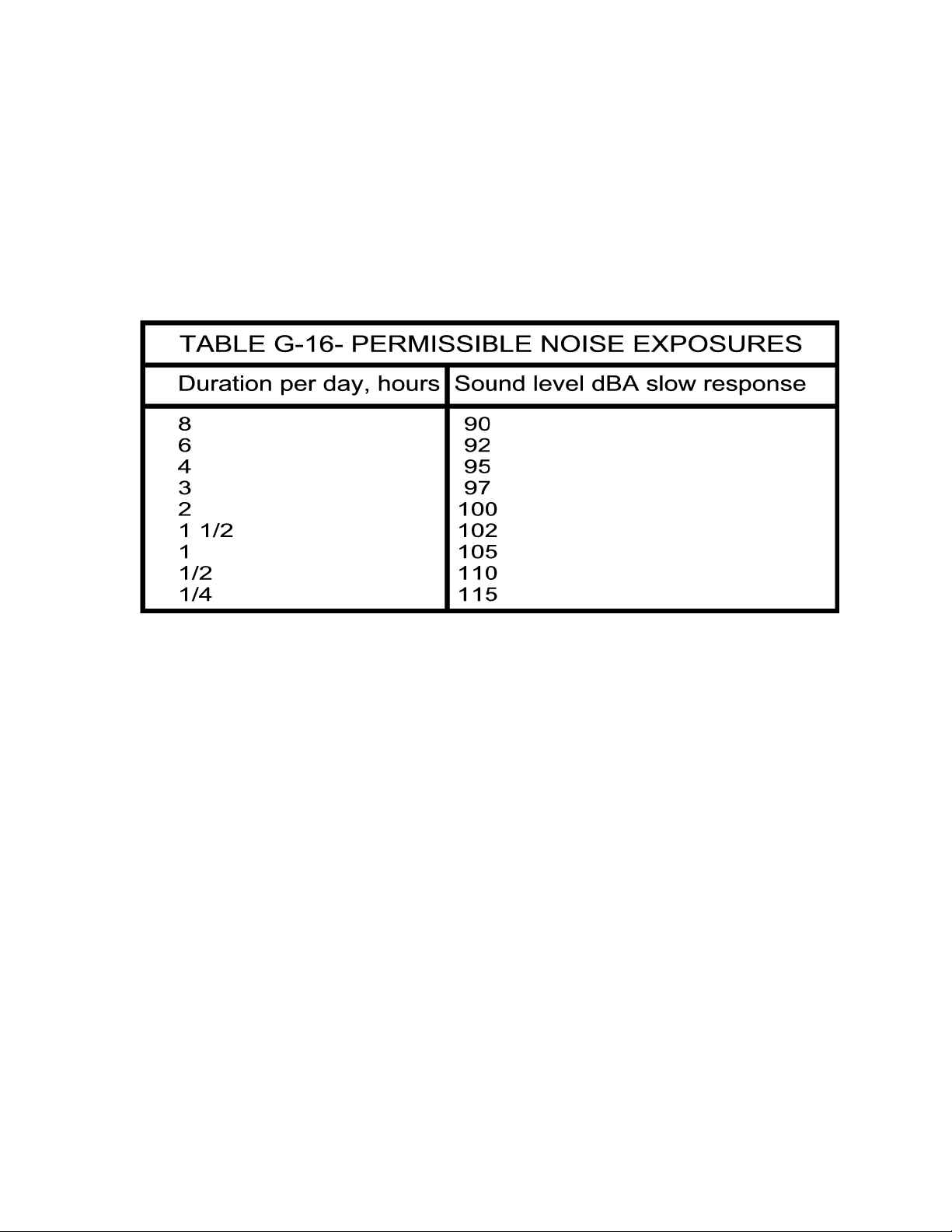
Caution: Exposure to extremely high noise levels can
cause permanent hearing loss.
The Tripower 15 speaker system is capable of producing in excess of 126db SPL at 1
meter. Continued exposure to noise levels in excess of 90db may cause permanent
hearing loss. Below is a chart of the OSHA (Occupational Safety & Health Administration)
regulations for Occupational Noise Exposure. Please note: OSHA requires hearing
protection for any work environment when the sound levels exceed those shown in Table
G-16 when measured on the A scale of a standard sound level meter at slow response.
INTRODUCTION
Thank you for purchasing ISP Technologies Tripower 15 active speaker system. The
Tripower 15 is a high output three-way active speaker system designed to deliver HI-FI
sound quality for high SPL sound reinforcement applications. The Tripower 15 is designed
with a 400-watt 15-inch woofer, a 300-watt 10-inch midrange driver and a high
performance, 2-inch high frequency compression driver. The Tripower 15 has three
separate power amplifiers capable of producing upwards of 700 watts of power. Each
amplifier receives its input signal from an internal 4th order crossover network specifically
designed to provide optimized phase and frequency response at each crossover point. The
internal amplifiers are based on ISP Technologies patent pending D-CAT (Dynamic Current
Amplifier Technology) amplifier technology. The D-CAT technology is capable of delivering
extremely high output current providing an improvement in transient response, output
current, and a noticeable improvement in PUNCH. The D-CAT amplifier technology utilizes
a monolithic power amplifier driver that reduces parts count and greatly improves reliability.
The D-CAT amplifiers provide improved reliability by including short circuit and over
temperature protection.
The Tripower 15 offers both ¼ inch RTS and XLR balanced inputs as well as, ¼-inch RTS
and XLR outputs for connecting multiple speakers. A sensitivity adjustment knob allows
you to adapt the speaker for a wide range of common signal levels. The Tripower cabinet
is made of high quality 13 ply Baltic birch plywood with a durable spray on black finish for
long life.
Page 4

PLACEMENT
The Tripower 15 is designed to sit on the floor or stage. Do not position or mount the
cabinet where it can tip over and fall on someone. Do not attempt to mount the cabinet on
speaker stands. Do not attempt to ‘fly’ (suspend by cables, chains, ropes, etc.) the cabinet.
It was not designed for flying. Position it only on a flat, stable surface where it is not in
danger of tipping over.
Also, note that the placement of the cabinet relative to floors and walls will affect the low
frequency response (below about 500 Hz.). Placing it closer to the floor and walls will
reinforce the low frequency response. The closer it is, the higher in frequency this
reinforcement will go. Also, make sure that adequate space (at least 6 inches) is left
behind the cabinet for airflow over the amplifier heatsink.
REAR PANEL DESCRIPTION
1. POWER SWITCH-This switch provides power to the Tri-Power power amp section. This
switch is a three-position switch where center is OFF and the outer positions are ON.
2. POWER INLET MODULE-This module provides a connection for the power cord and also
houses the mains fuse. (See Fuse Replacement Section)
3. INPUT GAIN- This control determines the overall input level of the signal to the power
amp section of the Tri-Power cabinet. Adjusting this level will not affect the level of the
signal passing through to output connectors.
Page 5

4. BALANCED ¼” PHONE INPUT-This jack provides an input for balanced or unbalanced
line level signal source.
5. BALANCED XLR INPUT-This female XLR connector provides an input for balanced line
level signal source
6. BALANCED ¼” PHONE OUTPUT – This ¼” phone provides a balanced loop through for
connecting to additional powered cabinets.
7. BALANCED XLR OUTPUT- This XLR male provides a balanced loop through for
connecting to additional powered cabinets.
FUSE REPLACEMENT
1. Use a small screwdriver as shown to slide the fuse cover
out from the power inlet module. The fuse can be found
inside the fuse cover module after it is pulled out.
NOTE: A SMALL COMPARTMENT IS ALSO PROVIDED WITHIN THE FUSE COVER
MODULE FOR STORING A SPARE FUSE.
2. After replacing the fuse with another of identical
specifications, push the fuse cover module fully back into
place, ensuring that the fuse has snapped onto the fuse
holder inside the power inlet module.
Page 6

CONNECTION DIAGRAM
BALANCED CONNECTION DESCRIPTION
The ISP Tripower series has balanced XLR and ¼” phone inputs and outputs
configured to AES standards (Audio Engineering Society). These connections
are connected in a loop through configuration and will accept a balanced linelevel input. The standard phase configuration is that pin 2 is (+), pin 3 is (-),
and pin 1 is shielded ground on the XLR. On the ¼” phone jacks the
configuration is Tip is (+), Ring is (-), and Sleeve is ground.
NOTE: IF AN UNBALANCED SIGNAL SOURCE IS USED, THE MALE XLR AND ¼”
PHONE OUTPUTS FOR LOOPING THROUGH TO ADDITIONAL POWERED
CABINETS WILL ALSO BE UNBALANCED.
Page 7

THERMAL CONDITIONS
The ISP Tripower 15 Series is capable of producing in excess of 700 watts at full power.
This generates heat that must be dissipated in order to maintain reliability and insure the
amplifier components stay within their operating temperature specs. To accomplish this, the
amplifier is mounted on a heatsink that is exposed on the rear of the cabinet. Airflow is
forced through a bass port at the bottom of the fins of the rear heatsink via the air movement
from the 15” speaker. It is recommended that the fins have at least 6 inches of clearance
from any obstruction to allow proper ventilation to occur.
In addition, the amplifiers are thermally protected internally via a thermal switch, which will
attenuate the signal 40db if the heatsink temperature exceeds a certain temperature. When
the temperature drops below a certain point, full signal will be restored. Tests have shown
under extreme conditions that cycling will occur approx. (40 sec. ON, 20 sec. OFF)
Under extreme conditions, such as when ambient temperatures are too high (hot rooms,
extreme outdoor temperatures) it is recommended to use a fan on the fins to reduce the
cycling effects.
It should also be noted that a separate internal thermal breaker also protects the power
transformer. If the power transformer temperature reaches a critical point, the internal
thermal breaker will open. The power LED on the front of the cabinet will go out and the
Tripower 15 will shut down for several minutes while the power transformer cools. If this
condition occurs, simply reduce the signal level of the system. This will only occur if the
Tripower 15 is continually pushed into heavy distortion.
NOTE: The power transformer inside the Tripower 15 contains an enamel coating on the
wires. During the first several hours of heavy use, the Tripower 15 may have a slight odor
caused by the enamel on the transformer wires heating.
Page 8

SPECIFICATIONS
System
Frequency Range 40Hz - 20KHz
Frequency Response (-3dB) 45Hz - 17KHz
Horizontal Coverage Angle 90 degrees.
Vertical Coverage Angle 40 degrees.
Peak Output @ 1m 126 dB
Crossover Points 350Hz, 2.2KHz
Input Type Balanced differential
Input Impedance 10K ohms
Thermal Protection Output Drivers have internal protection, self resetting. Heatsink
Transducers
Low-Frequency Transducer
Diameter 15” (381mm)
Voice Coil Diameter 3” (76.2mm)
Power Handling 400 watts RMS
Mid-Frequency Transducer
Diameter 10” (254mm)
Voice Coil Diameter 2.5” (63.5mm)
Power Handling 300 watts RMS
High-Frequency Transducer
Diaphragm Diameter 2” (51mm)
Voice Coil Diameter 2” (51mm)
Throat Size 1” (25.4mm)
Power Handling 80 watts RMS
Diaphragm Material Titanium
Power Amplifiers
Low-Frequency Amplifier
Power Output 400 watts RMS
THD <0.05% typical
Mid-Frequency Amplifier
Power Output 300 watts RMS
THD <0.05% typical
High-Frequency Amplifier 80 watts RMS
THD <0.02% typical
Line Input Power
Voltage 117Vac, 60 Hz
Current 6.9 amps
Power 800 watts
Physical
Height 41” (1041mm)
Front Width 20” (508mm)
Rear Width 11” (280mm)
Depth 18” (457mm)
Weight 120 lbs.
Enclosure 18mm thick, 13 ply Baltic Birch plywood
Geometry Trapezoidal, 15-degree angle sides
Mounting Methods Floor mount
temperature monitored and input is muted if safe temperature is exceeded,
self-resetting. Transformer has internal thermal fuse, self-resetting.
Page 9

WARRANTY AND SERVICE
The Internal Circuitry is fully guaranteed to be free of defects under normal use and service
for a period of three years from the date of purchase. The Speakers and Cabinet that are
used in this product are fully guaranteed to be free of defects under normal use and service
for a period of three years
Any damage resulting from the misuse or the failure to follow the precautions and instructions
will void the warranty.
In the event that the unit needs to be repaired. Please return the unit to ISP Technologies
directly. Simply repack the unit, send a copy of the original receipt, a note stating the
problem, and send it to:
ISP Technologies, LLC
5479 Perry Drive Suite B
Waterford, Mi. 48329
Attn: Repair Dept.
All shipping charges must be fully prepaid.
ISP will not be responsible for any damages incurred in shipping of any unit. Any claim will
need to be settled with the shipping company.
The warranty will be voided if the serial number has been tampered with in any way.
Should you have any questions for the repair department prior to returning the product
please call 1-(248)-673-7790
NOTE: This Product may be covered under one or more of the following patents or patents
pending: 7,035,413; 6,944,305; 6,931,134; 6,831,514; 6,091,013
NOTE: If it is determined that the power amp module has failed, it is possible for an ISP
certified service center to remove the module from the cabinet by removing the mounting
screws and disconnecting the speaker terminals and the transformer. The module may be
sent back to ISP separately. Please contact ISP for technical support to help determine if the
amplifier module may be defective.
ISP TECHNOLOGIES, LLC
5479 Perry Drive Suite B
Waterford, MI. 48329
248-673-7790
FAX: 248-673-6796
WWW.ISPTECHNOLOGIES.COM
 Loading...