

Page 1
Page 2

INTRODUCTION
Congratulations on your purchase of the THETA PRO DSP™. The THETA PRO DSP™ was
designed to provide the ultimate sonic performance possible in a Guitar DSP based processor; all
controlled on the floor, with simplicity of use and programmability. The THETA PRO DSP™ is based
on state of the art Digital and Analog circuit design and technology and features ISP Technologies
proprietary algorithms for all THETA PRO DSP™ functions. The THETA PRO DSP™ also features
the patented Decimator noise reduction system for the highest level of noise reduction and
transparency available. Also included on board is a SONG mode allowing the guitarist to arrange
presets into 124 songs with 4 preset patches per SONG. Please read this manual carefully for a
through explanation of the THETA PRO DSP™ and its functions.
IMPORTANT SAFTEY INSTRUCTIONS
Please read the following very carefully before operating this unit
Read ALL instructions carefully before using this unit. Keep these instructions for future reference. Heed all
warnings and follow all instructions.
Do not use this unit near water, in the rain, or where there is moisture. If this warning is ignored a serious
electrical shock or death may occur.
Do not attempt to service this unit. No user serviceable parts inside. Refer servicing to qualified, ISP
approved personnel. Servicing is required when the unit is damaged in any way, such as power adaptor is
damaged, liquid has been spilled into the unit, the unit has been exposed to rain or moisture, does not
operate normally, or has been dropped.
Care should be taken to avoid spilling any foreign objects or liquid into this unit. Avoid exposure of this
equipment to dripping or splashing and ensure that no objects filled with liquid, such as vases, are placed on
the equipment.
Only use accessories or attachments that are specified by the manufacturer.
Failure to follow these instructions may void the warranty.
NO USER SERVICABLE PARTS INSIDE. REFER SERVICING TO
QUALIFIED ISP TECHNOLOGIES SERVICE PERSONNEL.
The lightning bolt triangle is used to alert the user to the risk of electric shock.
The exclamation point triangle is used to alert the user to important operating or
maintenance instructions.
POWER REQUIREMENTS
This unit requires the connection of the external AC Power Adaptor to a 120 volt AC
outlet. Do not attempt to connect this unit to any power source other than the one
supplied with the THETA PRO DSP. The THETA PRO DSP will typically draw on
the order of 1.5 amps of current from the AC power adaptor when in use.
Page 3
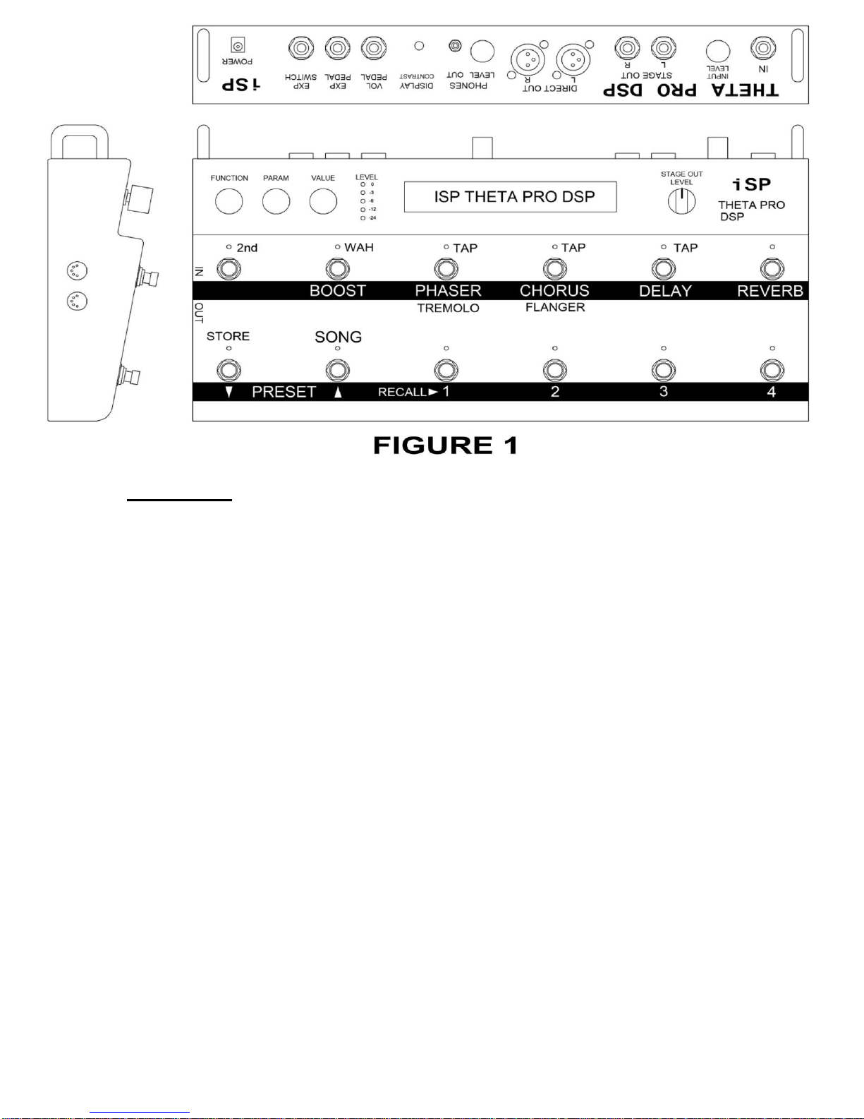
Quick Start
Refer to the Figures shown for the hardware drawings which show the locations of
the switches, knobs, and jacks when reading the following, or even better, just look
at your unit.
1. Connect the guitar to the IN jack, connect the STAGE OUT jack(s) to a power
amp such as the ISP Stealth which is connected to a guitar speaker cabinet, OR
connect the DIRECT OUT jacks to the input of a mixer, OR connect the
PHONES jack to headphones or earbuds (or connect all three). With a mono
system, the output(s) can be set to mono in the global parameters later. The
STAGE OUT jacks can be connected to a conventional guitar amplifier, but this
will not yield optimum results, since most guitar amps will further shape and
distort the sound.
2. Connect the supplied 9V AC power adaptor to wall power, then to the POWER
input on the Theta Pro. The unit will power up and recall Preset 1. Pressing the
RECALL 1 switch will display the Preset 1 title.
3. With the Preset title displayed, adjust the INPUT LEVEL control on the back
panel so that the LEVEL 0 LED (red) just flashes when playing hard, then back
off the INPUT LEVEL control slightly so that the 0 LED does not light. Short,
infrequent flashes of the red 0 LED are generally not audible. Adjust the STAGE
OUT LEVEL or PHONES LEVEL controls to taste. The DIRECT OUT levels can
be controlled by the global DIRECT TRIM parameter which affects all presets,
and by the OUTPUT LEVEL parameter within each preset, which affects all
outputs, but is the level specific to each preset. Note that the LEVEL LEDs only
display the raw input level when the preset or song titles are displayed
(FUNCTION turned fully counterclockwise). If any other parameters are
displayed, the LEVEL LEDs will display the maximum of the 4 output DAC
(Digital to Analog Converter) levels.
Page 4

4. Play!
5. Presets can be selected by pressing the PRESET down or up switches, then
the RECALL 1 switch. Holding the PRESET down or up switches will result in
progressively faster scrolling through the preset titles. The RECALL 2 switch
will immediately increment one preset, and the RECALL 3 switch will
immediately decrement one preset. These can be used to step through the
presets to try them out. The RECALL 4 switch will jump back to the last
previously recalled preset, easy to remember since it is the last switch on the
right. If the preset title is displayed (if FUNCTION is set fully
counterclockwise), the VALUE knob can be turned to scroll through the preset
titles. Pressing the RECALL 1 switch will then recall the selected preset.
6. BOOST, PHASER, TREMOLO, CHORUS, FLANGER, DELAY, and REVERB
can be turned on or off by the top row of switches, depending on the settings
within each preset.
7. Pressing the SECOND switch allows access to the WAH on/off, STORE, and
SONG Mode, as well as TAP functions to set the modulation rates and
DELAY time. The FUNCTION knob selects the function such as Preamp,
EQ, etc. The PARAM knob selects the parameter within the function, and the
VALUE knob adjusts the value.
8. Changing a value will light the red STORE LED. To store the new value for
later recall, press the 2nd switch, followed by the STORE switch. Note that the
THETA PRO DSP ships with the Preset 1-100 and Preset 101-200 LOCK set
to ON, so storing to those presets will display a FAIL message. Storing to
presets 201-224 is always allowed. See the section on the Global
Parameters for more information on how turn off the Locks.
9. To copy a preset to a different location, first recall the preset. Then scroll to
the desired new location by using the PRESET down or up switches, or the
VALUE knob (if FUNCTION is set fully counterclockwise). Note that the
preset titles will flash, meaning the preset is not fully recalled. Then press 2nd,
STORE to store the last recalled preset into the new location. The original
contents of this location will be overwritten, so be careful. The unit ships with
100 unique presets written in locations 1 to 100, then repeated again in
locations 101 to 200, we recommend that one of the two banks be left locked
to prevent inadvertently writing over the original presets, at least until the
storage space is needed for new original presets.
10. Read the rest of the manual, it contains much valuable information to get the
most from your Theta Pro DSP!
Page 5
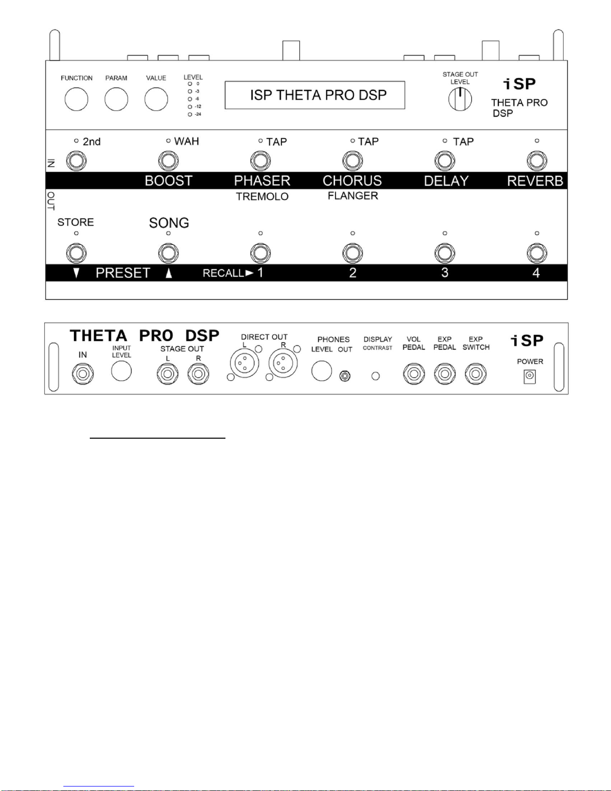
DETAILED OPERATION:
Refer to Figures above for the hardware drawings which show the locations of
the switches, knobs, and jacks when reading the following. Refer to Figure 2 for
the signal flow diagram which shows the flow of the signal through the unit from
the input to the outputs. The following text explains the operation of the unit
organized by the software functions and parameters, but it also incorporates
explanations of the hardware functions where they are interrelated to the
software. This fusion of both domains together helps to simplify the
understanding of the unit, since everything about a single concept is contained
together. Also, many important operational details are contained in the Quick
Start section, so reading and understanding that section is essential.
PRESET MODE:
This is the default mode when the unit is first turned on. It allows direct recall of
presets by name, adjustment and programming of presets, mapping of switches
and the expression pedal, MIDI Dump and Load, and setting of Global
parameters. The other mode of the unit is SONG MODE, which will be described
later.
Page 6

Functions and Parameters:
Note that the titles of the functions do not always appear on the display, but most
of them are contained within the first parameter of that function. The following list
of functions are accessed in order by turning the FUNCTION knob clockwise.
The parameters are then accessed by turning the PARAM knob. The values
displayed are changed by turning the VALUE knob.
A) Mixer Function
1. OUTPUT LEVEL (OFF to +10 dB): Controls the output level
feeding all outputs from the unit. This is to allow the presets to be
set to nominally equal levels given different gains, compression,
EQ, and effects. It also allows adjustment to prevent clipping of the
4 channel output DAC. When the Function is turned to display this
or any parameter other than the titles, the LEVEL leds will display
the maximum output level of the 4 DAC channels. The OUTPUT
LEVEL can then be adjusted to prevent clipping of the DAC by
keeping the red 0 dB LED from lighting.
2. DIRECT PAN (0 to 100): Pans the direct signal (the signal before
the stereo effects) from Left (0) to Right (100). The primary use for
this is to have the direct sent to one channel and the delay sent to
the other.
3. BOOST (OFF or ON): When ON, boosts the level of the signal
after the Preamp.
4. BOOST LEVEL (0 to 10 dB): Adjusts the amount of BOOST. Note
that if the preset already has a hot level, too much boost can clip
the output DACs.
B) PREAMP Function
1. PREAMP (CLEAN or DISTORT): In CLEAN, the distortion part of
the preamp is bypassed, so the DIST TYPE, GAIN, and SAG
parameters have no effect, and it is not possible to get clipping
within the preamp section, due to floating point processing. If you
are still hearing distortion, it is probably due to the input ADC or
output DACs being overdriven, or your guitar, amp, mixer,
speakers, headphones, or ears. In DISTORT, the distortion part of
the preamp is enabled, so all the parameters become active.
2. DIST TYPE (THETA or VINTAGE): THETA type applies an EQ
curve before the clipper stage that matches that of the ISP THETA
pedal. This is in addition to the settings of the PRE EQ controls.
VINTAGE removes this curve, so that the only pre-distort EQ is
what has been set on the PRE EQ controls. Real vintage amps do
not have much pre-clip EQ, but sound less desirable at high gain
settings.
Page 7

3. GAIN (1 to 90 dB): Dials up the gain before the clipper stage.
Additionally, there is gain available in the Pre EQ and THETA type
distortion, so that the total amount of gain applied to the signal can
exceed 120 dB! As a point of reference, a typical amp head has a
gain of about 60 dB with the knobs set to maximum. If the GAIN is
set above 60 dB, the compressor will be disabled, even if the
PREAMP is set to CLEAN. To re-enable the compressor, the GAIN
must be lowered to 60 or less, then the COMPRESSOR parameter
can be turned from OFF to ON.
4. SAG (0 to 100): Emulates the sag of the supply voltage rails in an
amp. Higher values result in more sag. As you play harder, the
rails sag down resulting in more clipping of the signal. Play softer
and the rails move higher, resulting in a cleaner sound. This is
most effective with moderate levels of GAIN.
5. OUTPUT LEVEL (OFF to +10 dB): This is the same parameter as
in the mixer function. It is just repeated here for convenience
because as preamp parameters are changed, it is typical that the
output level will need to be readjusted.
6. COMPRESSOR (OFF or ON): Turns on the compressor, which is
positioned before the clipper stage. Compression is useful for
making clean or low gain settings sound louder, as it reduces the
level of loud passages and increases the level of soft passages.
The downside is the more compression used via lowering the
threshold, the more noise is added to the signal. See the GAIN
parameter for an explanation of how it affects the compressor.
7. COMP THRESH (-30 to 0): The lower the setting, the more the
compression.
8. PRE BASS (-15 dB to +15 dB): The level of the pre-clip bass EQ.
Generally for distorted presets this is set to 0 or negative to get a
bass cut. For higher gains, these pre-EQ sections do not so much
affect the tone of the output, but rather affect the character of the
distortion.
9. PRE BASS (40 Hz to 240 Hz): The ‘turnover’ or upper frequency at
which the amount of pre bass boost or cut begins to lose effect.
Frequencies above this point will still be boosted or cut, just not as
much, and as frequency in the signal increases, the amount will
diminish to 0. This is a ‘shelf EQ’ type section that remains
nominally flat at low frequencies.
10. PRE MID (-15 dB to +15 dB): The level of pre-clip midrange EQ.
Generally for distorted presets this is set to a positive value to get a
boost in the mids.
See the graph on the next page for a better understanding of
the operation of a parametric equalizer.
Page 8
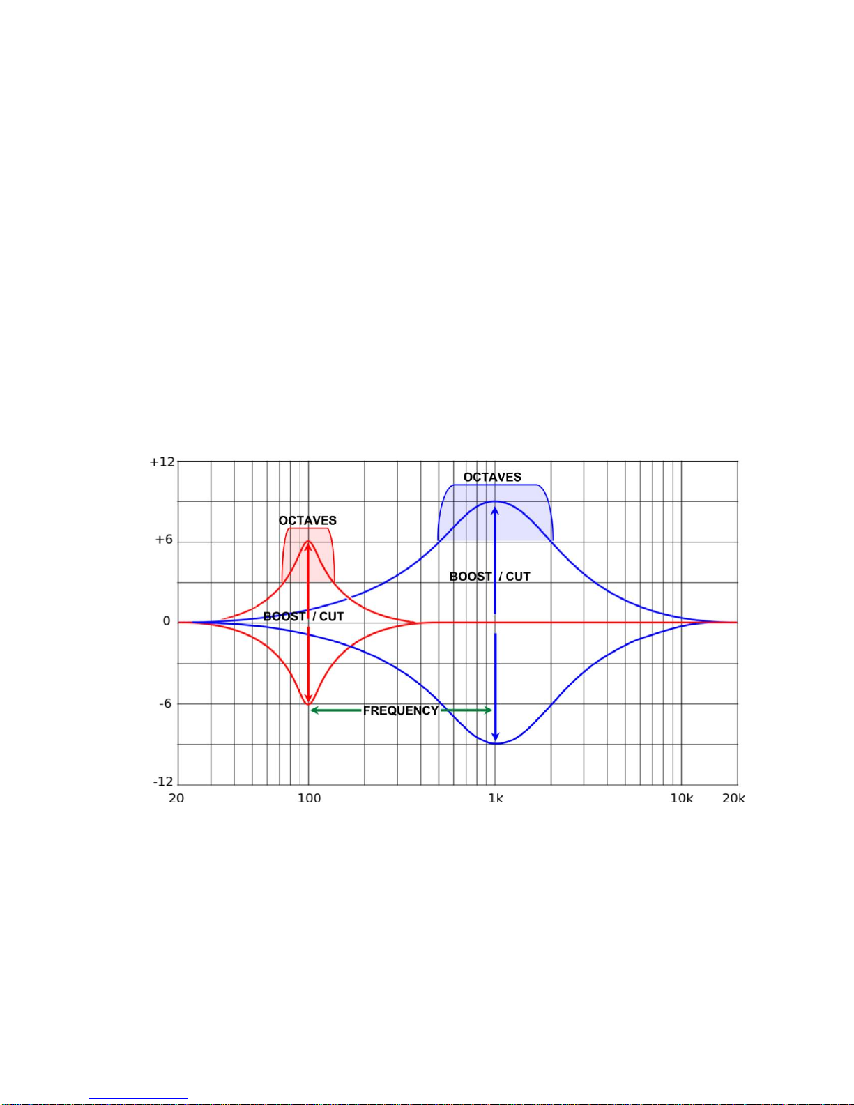
Note: there are three controls that adjust a parametric
equalizer including BOOST – CUT (LEVEL), FREQUENCY or
FREQUENCY SWEEP (FREQ) and BANDWIDTH or OCTAVES
(BW). The graph below shows an EQ response curve with a center
frequency of 100Hz and also at 1KHz. The MID “LEVEL” on the
THETA PRO DSP will adjust the amount of Boost or Cut applied to
the signal. The MID FREQUENCY, “FREQ” adjusts the center
frequency as shown below allowing you to select the center point or
peak frequency you are boosting or cutting. The MID BANDWIDTH
“BW” is the bandwidth of the frequencies being boosted or cut and
is selected as OCTAVES. An OCTAVE setting of .1 will be a
narrow band of frequencies that are affected by the boost or cut
approximately .1 octaves at 3bd down from the peak frequency. An
OCTAVE setting of 2.5 will be a much broader portion of the
spectrum that is affected by the boost or cut approximately 2.5
octaves at 3db down from the peak frequency. This type of
equalization allows much more precise adjustment of tone shaping
than typical Bass, Mid, Treble controls.
11. PRE MID (88 Hz to 6000 Hz): The center frequency of the
midrange boost or cut. It is typically set in the 300 to 2000 Hz
range.
12. PRE MID (0.1 to 2.5 OCT): The approximate width in octaves of
the midrange boost or cut. Beyond this width, the curve will slowly
transition back to 0 if the bass and treble are set flat.
13. PRE TREBLE (-15 dB to +15 dB): The level of pre-clip treble EQ.
14. PRE TREBLE (2000 Hz to 12.0kHz): The lower frequency at
which the amount of pre treble boost or cut begins to lose effect.
Page 9

Frequencies below this point will still be boosted or cut, just not as
much, and as the frequency in the signal decreases, the amount
will diminish to 0. This is a ‘shelf EQ’ type section that remains
nominally flat at high frequencies.
C) POST EQ Function
1. POST EQ (OFF or ON): Turns off or on the 4-band parametric EQ
section that follows the clipper. See the graph on the previous
page for an explanation of how a parametric equalizer works.
For distorted presets, these parameters have the largest influence
on the tone. The fully parametric nature of these sections with
adjustable frequencies and bandwidths give you the power to
create nearly any tone you want.
2. BASS (0 to +15 dB): The level of boost of the bass EQ.
3. BASS (40 Hz to 240 Hz): The ‘turnover’ or upper frequency at
which the amount of bass boost begins to lose effect. Frequencies
above this point will still be boosted, just not as much, and as
frequency in the signal increases, the amount will diminish to 0.
This is a shelf type section.
4. MID1 LEVEL (-15 dB to +15 dB): The level of cut or boost at the
center frequency in the first midrange section.
5. MID1 FREQ (88 Hz to 6000 Hz): The center frequency of the first
midrange section.
6. MID1 BW (0.1 OCT to 2.5 OCT): The approximate width in octaves
of the midrange boost or cut. Beyond this width, the curve will
slowly transition back to 0 if the bass and treble are set flat.
7. MID2 LEVEL (-15 to +15): The level of cut or boost at the center
frequency of the second midrange section.
8. MID2 FREQ (88 Hz to 6000 Hz): The center frequency of the
second midrange section.
9. MID2 BW (0.1 OCT to 2.5 OCT): The approximate width in octaves
of the midrange boost or cut.
10. TREBLE (-15 to +15 dB): The level of the treble EQ.
11. TREBLE FREQ (2000 Hz to 12.0kHz): The lower frequency at
which the amount of treble boost or cut begins to lose effect.
Frequencies below this point will still be boosted or cut, just not as
much, and as the frequency in the signal decreases the amount will
diminish to 0. This is a ‘shelf EQ’ type section that remains
nominally flat at high frequencies.
DECIMATOR Function
12. DECIMATOR (OFF or ON): Turning the VALUE knob turns off or
on the DECIMATOR noise reduction.
Page 10

13. THRESHOLD (-90 dB to –20 dB): The approximate signal level at
which the DECIMATOR will begin downward expansion of the input
signal, effectively turning off the noise. Higher threshold values are
needed to deal with higher levels of noise. Since the detector for
the DECIMATOR is at the very input of the digital signal processing
chain, this threshold does not usually have to be re-adjusted
because of changes in the preamp settings, but using very high
values of gain may make the residual noise more apparent, so you
will want to set this to a higher value on those presets.
D) INTELLIGENT SPEAKER™ (INTELLIGENT SPKR™) Function
1. INTELLIGENT SPKR™ (OFF or ON): This turns on the speaker
filter function. It achieves virtually identical sound to a microphone
on a speaker cabinet, since it convolves the signal with actual
samples of a microphone on a speaker cabinet. This function
always affects the signal output on the Direct and Headphone
outputs, but will also affect the Stage Outputs if the Global
parameter ‘STAGE SPKR SIM’ is set to ON. This parameter is
useful if using the Stage Outputs to drive a full-range speaker such
as a vocal wedge or even in-ear monitors, and use the STAGE
OUT LEVEL control to vary the level independently from the
DIRECT OUT signal, which typically feeds the front of house
system in a live situation, or mixer/DAW inputs in a recording
situation.
2. Type (4x12 Greenback, 1x12 Creamback, 1x12 Deluxe, 4x10 59 Bman, 2x12 Twin, or Lowpass Filter): Of these, only the Lowpass
Filter is not based on measurement of an actual speaker, but is
simply a fourth order lowpass filter approximation to a guitar
speaker. Some may like its sound for certain uses, but it serves as
a comparison to the sound of less advanced speaker simulations.
3. REACTANCE (-6 to +6): Bass boost or cut level. This simulates
the bump in the bass that can occur with a tube amp interacting
with the LF impedance bump (the reactance) in a speaker. It
allows you to adjust the bass further to your liking.
4. MIC POSITION (-6 to +6): This simulates moving the microphone
from the edge of the cone to the center of the cone by appling a
high frequency shelf EQ.
E) WAH Function
1. WAH (OFF or ON): Turns the WAH on or off. There are four ways
the WAH can be turned on or off. One is by accessing this
parameter and turning the VALUE knob. The second is by pressing
the 2nd switch (if it is not already on), then pressing the
BOOST/WAH switch. The third is to connect an expression pedal
with a switch to the EXP. SWITCH jack on the rear panel with a
Page 11

mono (2 conductor) ¼” cable and press down on the expression
pedal, just like on a separate wah-wah pedal. For this to work, the
EXP SWITCH parameter within the EXP PDL function must be set
to WAH. The fourth way in which the WAH function is turned on is
by recalling a Preset with this WAH parameter set to ON.
2. WAH FREQ (500 Hz to 3084 Hz): The wah center frequency. A
wah-wah pedal is a peaking filter with user variable center
frequency inserted in the signal path. A classic Cry-Baby wah
pedal will have a typical frequency range from about 1000 Hz to
2800 Hz, so the range available here is greater. This frequency
can be adjusted by turning the VALUE knob, but the usual method
is to connect an expression pedal which has a linear potentiometer
(pot) to the EXP. PEDAL jack on the rear panel with a ¼” stereo
cable (3 conductor with ring-tip-sleeve or RTS plugs). The EXP
PDL1 or EXP PDL2 parameters must be set to WAH FREQ, and
the corresponding EXP MIN and EXP MAX parameters can be set
the minimum and maximum frequency values you want to sweep
over. This allows you to limit the range to equal that of a classic
wah pedal if you wish. But the MIN and MAX values you set will
only be reached if the pot in your expression pedal sweeps from 0
ohms to the full maximum resistance of the pot within the pedal,
which often is not the case. So the actual MIN and MAX values
you reach may cover a slightly reduced range. See also the
EXPRESSION PEDAL Function.
3. WAH LEVEL (0 to +10): Controls the level near the center
frequency of the wah. Since the wah filters off frequencies away
from the center frequency, the audible level will typically go down
when the wah is switched in. This allows you to boost the level
back. Clean presets will require more boost, while higher gain
presets will require less because the increased harmonic content of
the distorted signal will tend to fall within the passband of the wah
filter.
F) TREMOLO Function
A tremolo works by simple amplitude (volume) modulation of the signal. It
has a MONO output.
1. TREMOLO (OFF or ON): Turns it off or on. The tremolo can also
be turned on or off by pressing the switch marked
PHASER/TREMOLO, if the P/T SWITCH parameter within the
Switch function is set to TREMOLO or PHA+TREM.
2. TREM DEPTH (0 to 100): Controls the depth, which is the amount
of amplitude modulation.
3. TREM RATE (1 to 127): Higher numbers give faster rates. The
rate can also be controlled by pressing 2nd, then pressing twice
Page 12

(tapping) on the PHASER/TREMOLO switch, if the P/T switch is set
to TREMOLO, or if it is set to PHA+TREM and the tremolo is ON.
G) PHASER Function
A phaser works by running the signal through an all-pass filter to shift its
phase as a function of frequency, then mixing this signal back into the
original signal, creating a series of notches in the frequency response,
also known as a comb filter. The amount of phase shift is modulated up
and down, resulting in the notches shifting up and down in frequency
depending on the rate setting. It has a mono output.
1. PHASER (OFF or ON): The phaser can also be turned on or off by
pressing the switch marked PHASER/TREMOLO, if the P/T
SWITCH parameter within the Switch function is set to PHASER or
PHA+TREM.
2. RESONANCE (OFF to –2): Controls the amount of feedback within
the phaser. This affects the shape of the notches or ‘teeth’ of the
comb filter, and also the time-domain decay of the response.
3. PHASER DEPTH (0 to 100): Controls the mix between the original
signal and the phase shifted signal, which varies the depth of the
notches in the comb filter, and hence the amount of the effect.
4. PHASER RATE (1 to 127): Higher numbers give faster rates. The
rate can also be controlled by pressing 2nd, then pressing twice
(tapping) on the PHASER/TREMOLO switch, if the P/T SWITCH is
set to PHASER, or if it is set to PHA+TREM and the phaser is ON.
5. PHASER STAGES (4, 6, 8 or 10): The number of stages in the allpass filter, which gives more phase shift, which then results in more
notches in the comb filter. A certain widely used ‘classic’ phaser
pedal has 4 stages.
H) CHORUS/PSHIFT Function
In V2 software, the CHORUS function has been modified by addition of
PITCH SHIFT mode. When the pitch shift is active, the chorus is disabled.
A new parameter has been added to the chorus to switch between the two
modes. The pitch parameters are accessed by turning the FUNCTION
knob one click clockwise, then using the PARAM knob to select the
parameter to adjust.
A chorus works by running the signal through a short delay of about 20
ms, and mixing the delayed signal with the original. The delay time is
modulated according to the rate and depth, creating a small amount of
pitch bend in the delayed signal. The Theta Pro DSP has 4 voices, each
separately delayed, modulated, and panned left or right, providing a lush
stereo output.
1. CHORUS (OFF or ON): Controlled via VALUE knob or the
CHORUS/FLANGER switch. For footswitch control, the C/F
Page 13

SWITCH parameter within the Switch function must be set to
CHORUS or CRS+FLA.
2. CRS MODE (CRS or PSHIFT): switches between the modes.
3. CHORUS MIX (0 to 100): Controls the relative mix between the
original signal and all 4 delayed voices.
4. CRS DEPTH 1 (0 to 100): Varies the amount of change in the
delay time, which varies the amount of pitch bend in Voice 1.
5. CRS RATE 1 (1 to 127): Varies the rate at which the pitch is
being modulated. The rate can also be controlled by pressing 2nd,
then pressing twice (tapping) on the CHORUS/FLANGER switch,
if the C/F SWITCH is set to CHORUS, or if it is set to CRS+FLA
and the chorus is ON.
6. CRS LEVEL 1 (OFF to 0 dB): Controls the level of voice 1 that is
mixed in the stereo output.
7. CRS PAN 1 (0 to 100): Pans voice 1. 0 is fully Left, 100 is fully
Right, and 50 is centered.
8. CRS DEPTH 2 (0 to 100): Same as for voice 1.
9. CRS RATE 2/1 (0.1 to 1.5): Sets the ratio between the rate of
voice 2 and the rate of voice 1. It is done this way so that if the
rate of voice 1 is varied by either the VALUE knob, the TAP
function, or the EXP. PEDAL function, the rate of all 4 voices will
track each other. Typically these ratios are set to a value other
than 1.0, so that each voice will modulate at a different rate
resulting in a more random and ‘lush’ sounding effect.
10. CRS LEVEL 2 (OFF to 0 dB): Same as for voice 1.
11. CRS PAN 2 (0 to 100): Same as for voice 1.
12. The explaination for voices 3 and 4 the same as for voice 2.
A pitch shifter works by storing the signal in a short delay, then reading it
out at a faster (shift up) or slower rate (shift down). For a shift up, this means
that portions of the signal must be repeated. For a shift down, portions of the
signal are thrown away. For either case, the output signal will be spliced
together from portions of the input. The Theta Pro has an intelligent algorithm to
find 'best match' splice points to minimize their audibility. Presets 210 to 220
have been re-written to utilize the pitch shifter.
1. PITCH (-1200 to +1200 CENTS): Varies the amount of pitch shift in 20
cent increments. -1200 cents is one octave down, +1200 cents is one
octave up, and each 100 cents is one semitone. This parameter can
mapped to the expression pedal for real-time foot controlled pitch
bending, as in the "WHAM ME" preset.
2. DETUNE (-25 to +25 CENTS): Varies the amount of pitch shift in 1
cent increments to achieve a slight detune effect. The total pitch shift
will be the addition of the PITCH and DETUNE values, but typically
PITCH will be set to 0 if DETUNE is being used. An exception to this
is in the "12 STRING" preset, where a slight detune is used off a full
Page 14

octave shift.
3. PSHIFT MIX (0 to 100): Controls the relative mix between the original
signal and the pitch shifted voice.
4. PSHIFT PAN (0 to 100): Pans the pitch shifted voice. 0 is fully Left,
100 is fully Right, and 50 is centered.
5. DIRECT PAN (0 to 100): Pans the direct voice. This is a repeat of the
same parameter from the Mixer Function. It is repeated here for
convenience.
I) FLANGE Function
The flanger works in a very similar fashion to the chorus, except the
variable delay time is much shorter, resulting in the predominate effect
being a modulated comb filter, not a pitch bend. It is therefore similar
sounding to the phaser, but since it uses time delay the resulting phase
shift is linear with frequency, whereas the all-pass filters used in the
phaser are not. The result is that the notch frequencies in the flanger
have a different spacing, and there are many more of them. There are
also two voices in the flanger. These are panned hard left for voice 1 and
hard right for voice 2, removing the need for Level and Pan parameters.
Using Phase and Flange at the same time may be interesting results.
1. FLANGE (OFF or ON): Controlled via VALUE knob or the
CHORUS/FLANGER switch. For footswitch control, the C/F
SWITCH parameter within the Switch function must be set to
FLANGER or CRS+FLA.
2. FLA REGEN (OFF to –2 dB): Controls the amount of feedback
within the flanger. This affects the shape of the notches or ‘teeth’ of
the comb filter, and also the time-domain decay of the response,
resulting in a more dramatic effect. But as in real life, you can get
tired of too much ‘drama’.
3. FLA DEPTH 1 (0 to 100): Varies the amount of change in the delay
time, which varies the amount of change in frequency of the
notches in Voice 1.
4. FLA RATE 1 (1 to 127): Varies the rate at which the notch
frequencies are being modulated. The rate can also be controlled
by pressing 2nd, then pressing twice (tapping) on the
CHORUS/FLANGER switch, if the C/F SWITCH is set to
FLANGER, or if it is set to CRS+FLA and the flanger is ON.
5. FLA DEPTH 2 (0 to 100): As described for voice 1.
6. FLA RATE 2/1 (0.1 to 1.5): Sets the ratio between the rate of voice
2 and the rate of voice 1. It is done this way so that if the rate of
voice 1 is varied by either the VALUE knob, the TAP function, or
the EXP. PEDAL function, both rates will track each other.
J) DELAY Function
Page 15

a. DELAY (OFF or ON): Turns the delay OFF or ON. Controlled by
the VALUE knob or the DELAY switch. Turning the Delay OFF
mutes both the input and output of the delay, so the delayed output
stops immediately.
b. DELAY LEVEL (OFF to 0 dB): Controls the level of the delayed
signal.
c. REGEN LEVEL (OFF to 0 dB): Controls the level of successive
repeats of the delay, and therefore the number of repeats that can
be heard. If set to –10 dB, each echo will be 10 dB lower than the
one before it.
d. DELAY TIME (10 ms to 1300 ms): 1300 ms = 1.3 seconds. The
delay time can also be set by pressing the 2nd switch, then pressing
twice (tapping) on the DELAY switch. The time interval between
taps will set the delay time. You can tap twice again to change the
setting. If the interval between taps exceeds 1300 ms, the delay
time will be set to 1300ms. If you only tap once, after a few
seconds the time will be set to 1300 ms. Press 2nd again to exit the
tap function.
e. DELAY PAN (0 to 100): Pans the delay output. 0 is fully Left, 100
is fully Right, and 50 is centered.
K) REVERB Function
a. REVERB (OFF or ON): Turns the reverb OFF or ON. Controlled
by the VALUE knob or the REVERB switch. Turning the Reverb
OFF mutes only the input to the reverb, so the reverberated output
‘spills over’, even if set to OFF in the next preset.
b. REVERB DECAY (0 to 99): Sets the relative decay time of the
reverb.
c. REVERB HFDAMP (0 to 99): Set at 0, the highs will decay at the
same rate as the lower frequencies. At larger settings, the highs
will decay more rapidly than the lows, so the room will sound
‘darker’. A setting of around 20 will sound more natural, since real
rooms always absorb high frequencies faster than lows.
d. ROOM SIZE (SMALL, MEDIUM, or LARGE): With other settings
being equal, a larger room will have a longer decay time, since it
will take more time for the sound to travel from one surface to
another.
L) SWITCH Function
a. P/T SWITCH: (PHASER, TREMOLO, or PHA+TREM): Determines
the action of the PHASER/TREMOLO switch and LED. Set to
PHASER, the switch will turn off or on the phaser, or if 2nd is
activated, the switch will allow tap setting of the phaser rate. The
LED will show the phaser is on by blinking at the set rate. If this
Page 16

parameter is set to TREMOLO, the switch will turn off or on the
tremolo, or if 2nd is activated, the switch will allow tap setting of the
tremolo rate. The LED will show the tremolo is on by blinking at the
set rate. If this parameter is set to PHA+TREM, the switch will turn
on both functions if they are both off, or turn them both off it they
are both on. If only one is on, the switch will turn that function off
and the other one on. If both phaser and tremolo are on, the LED
will display the rate of the phaser, since that is considered the most
typical use of the switch.
b. C/F SWITCH: (CHORUS, FLANGER, or CRS+FLA): Determines
the action of the CHORUS/FLANGER switch and LED. Set to
CHORUS, the switch will turn off or on the chorus, or if 2nd is
activated, the switch will allow tap setting of the chorus rate. The
LED will show the chorus is on by blinking at the set rate. If this
parameter is set to FLANGER, the switch will turn off or on the
flanger, or if 2nd is activated, the switch will allow tap setting of the
flanger rate. The LED will show the flanger is on by blinking at the
set rate. If this parameter is set to CRS+FLA, the switch will turn on
both functions if they are both off, or turn them both off it they are
both on. If only one is on, the switch will turn that function off and
the other one on. If both chorus and flanger are on, the LED will
display the rate of the chorus, since that is considered the most
typical use of the switch.
M) EXPRESSION PEDAL Function
a. EXP PDL1 (OFF, WAH FREQ, GAIN, DIRECT PAN, TREBLE,
TREBLE FREQ, PHASER RATE, PHASER DEPTH, CRS RATE 1,
CHORUS MIX, FLA RATE 1): Allows you to map the EXP PEDAL
input to the selected parameter. Select OFF if you don’t want the
expression pedal to be able to change any parameters.
b. EXP MIN1 (various): Allows you to set the minimum range of the
expression pedal sweep. The units that appear with this parameter
will change to match the units of the parameter selected above in 1.
c. EXP MAX1 (various): Allows you to set the maximum range of the
expression pedal sweep. The units that appear with this parameter
will change to match the units of the parameter selected above in 1.
d. EXP PDL2 (OFF, WAH FREQ, GAIN, DIRECT PAN, TREBLE,
TREBLE FREQ, PHASER RATE, PHASER DEPTH, CRS RATE 1,
CHORUS MIX, FLA RATE 1): Allows you to map the EXP PEDAL
input to the selected parameter. This parameter exists to allow you
to map the expression pedal to two parameters from the list, for
even greater creative control. Select OFF if you do not want to use.
e. EXP MIN 2 (various): Allows you to set the maximum range of the
expression pedal sweep. The units that appear with this parameter
will change to match the units of the parameter selected above in 4.
Page 17

f. EXP MAX2 (various): Allows you to set the maximum range of the
expression pedal sweep. The units that appear with this parameter
will change to match the units of the parameter selected above in 4.
g. EXP SWITCH (OFF, WAH): Selects the ON/OFF function which is
controlled by the EXP SWITCH jack.
It is recommended to use a pedal with a linear taper pot, the resistance of
which is not critical, since the circuit is just reading the ratio of two voltages.
The ideal pedal for this is the Mission Engineering model EP1-KP. It has
two jacks, one is TRS (3 conductors) labeled OUT 1 for the potentiometer
(pot). Connect this jack via ¼” TRS cable to the EXP PEDAL jack on the
back of the Theta Pro. The second jack on the EP1-KP is labeled OUT 2.
Connect this jack via ¼” TS (2 conductor, standard jumper cable) to the EXP
SWITCH jack on the back of the Theta Pro, and the switch in the toe of the
pedal can be used to turn on the WAH. Other pedals can be used, but for a
standard volume pedal you will need a ‘Y’ cord which has a single ¼” TRS
(tip-ring-sleeve) jack at 1 end and two ¼” mono jacks at the other end,
assuming your volume pedal has separate IN and OUT jacks (sometimes
labeled INST and AMP). The ring of the EXP PEDAL jack supplies 3.3 volts
DC to the IN jack on the pedal, and the tip of the EXP PEDAL jack reads the
wiper voltage on the OUT or AMP jack of the pedal. If you connect them
backwards you won’t damage anything, but the parameter change will be very
abrupt in the bottom part of the pedal travel. Connecting them the other way
will result in most of the parameter change occurring at the top of the pedal
travel, if an audio taper pot is used. For most parameters, especially the
WAH frequency, a pedal with a linear taper pot is recommended for correct
functionality.
N) Title Edit Function
This displays the preset title. The PARAM knob selects the character
position to be edited, which moves the cursor under the character
selected. There are 16 character positions. The VALUE knob then
selects the particular letter, number, or symbol. When you are finished
editing the title, don’t forget to press 2
nd
, then STORE to save it.
O) Dump/Load Function
a. DUMP PRESET (ALL, 1 to 224): Selects the preset to be dumped
as a midi sysex message to the MIDI OUT jack. A single preset
can be dumped, or all presets. If ALL is selected, the GLOBAL
data, followed by all 224 presets, followed by all 124 songs will be
dumped. To initiate the dump, press 2nd, followed by STORE. A
“DUMPING …” message will be displayed, followed by “DUMP
Page 18

COMPLETE” when finished. For single presets, this will occur so
fast that only the “DUMP COMPLETE” message will be visible.
b. READY TO LOAD (ALL, 1 to 224): Selects the preset destination.
For example, preset 101 from a unit can be loaded into preset 21 of
another unit. If ALL is selected, the GLOBAL data, followed by all
224 presets, followed by all 124 songs will be loaded. No further
switch presses are needed on the receiving unit, rather it will just
wait for the data stream to start, and will then display “RECEIVING
MIDI” once data is detected, followed by “LOAD COMPLETE” when
finished. If there are errors detected in the data stream, the
message “DATA ERROR – NO LOAD“ will be displayed instead. If
this occurs, exit the Dump/Load function on each unit, check the
cable connection, then re-enter this function and try again. Note
that the only functions supported by the MIDI jacks are sysex dump
and load. Preset changes, parameter mods, etc. are not
supported.
There are two scenarios for use of the Dump/Load Function. The
first is the direct transfer of preset data from one Theta Pro DSP to
a second Theta Pro DSP. The second scenario is Dump/Load to a
MIDI recording device, which is usually a PC or MAC. For this you
will need a MIDI interface box, such as an iConnectivity iConnect
MIDI2, which interfaces MIDI to a PC via USB port. You will also
need software to record the sysex data and save it to disc, or load a
disc file and send to MIDI. One recommendation ISP has is to use
the MIDI-OX program, which can be readily found via a web search
and download. The files so obtained can be attached to emails.
P) Global Function
This function is the last one reached via the FUNCTION knob when in
Preset Mode. Even though it appears within every preset, there is only
one set of these parameters, and they affect all presets equally. To store
changes to these parameters, you must press 2nd, then STORE within this
function, before changing back to any other function. You should get in
the habit of checking the DECIM OFFSET and output EQ’s to reset them
every time you play in a different room or with different speakers. For the
touring musician, the FOH speakers may change in every different venue.
If time permits, you may want to take the THETA PRO DSP out into the
house, connect it, and adjust the DIRECT OUT EQ settings to your own
preference (or have your tech adjust them from the stage) at the start of
sound check. Just remember changes must be stored, or they will be lost
upon power down.
a. G:DECIM OFFSET (-20 to +20 dB): This number is added to the
Decimator THRESHOLD parameter in each preset, thus affecting
Page 19

the threshold in all presets equally. It is useful for situations where
you are playing with a different guitar or in a different environment,
where you need a temporary change in the decimator threshold,
without having to change decimator settings within individual
presets.
b. G: STAGE OUT (STEREO or MONO): When set to MONO, the left
and right STAGE OUTs will be summed and divided by 2. This is
useful when you only have a single speaker cabinet on stage.
c. G:STAGE SPKR SIM (OFF or ON): Typically this would be set to
OFF for using a traditional 1x12, 2x12, or 4x12 guitar cabinet on
stage. But if you want to use a full range cabinet such as a vocal
wedge, or even in-ear monitors, yet still control their volume via the
STAGE OUT LEVEL on the front of the unit, setting this to ON will
route the INTELLIGENT SPEAKER™ processed output to the
STAGE OUT jacks.
d. G: DIRECT OUT (STEREO or MONO): When set to MONO, the
left and right DIRECT OUTs will be summed and divided by 2. This
is useful when you only want a mono feed to the front of house.
Note that this will also affect the phones output, since they share
the same pair of DAC channels.
e. G: DIRECT TRIM (-12 to 0 dB): This attenuates the DIRECT OUTs
to prevent input clipping on some mixers.
f. G: DIRECT EQ (OFF or ON): This turns on a stereo 3-band EQ
section on the DIRECT OUTs. Remember, this EQ curve will then
be present on all presets, and is useful for making basic corrections
to speakers and rooms.
g. G: DIR BASS (-15 to +15 dB): Consult the POST EQ function for a
detailed explanation of these 7 EQ parameters.
h. G: DIR BASS (40 to 240 Hz):
i. G: DIR MID (-15 to +15 dB):
j. G: DIR MID (88 to 6000 Hz):
k. G: DIR MID (0.1 to 2.5 OCT):
l. G: DIR TREBLE (-15 to +15 dB):
m. G: DIR TREBLE (2000 to 12.0k Hz):
n. G: STAGE EQ (OFF or ON): This turns on a stereo 3-band EQ
section on the STAGE OUTs. Remember, this EQ curve will then
be present on all presets, and is useful for making basic corrections
to speakers and rooms.
o. G: STAGE BASS (-15 to +15 dB): Consult the POST EQ function
for a detailed explanation of these 7 EQ parameters.
p. G: STAGE BASS (40 to 240 Hz):
q. G: STAGE MID (-15 to +15 dB):
r. G: STAGE MID (88 to 6000 Hz):
s. G: STAGE MID (0.1 to 2.5 OCT):
t. G: STAGE TREB (-15 to +15 dB):
u. G: STAGE TREB (2000 to 12.0k Hz):
Page 20

v. G: VOLUME PEDAL (OFF or ON): This would normally be set to
ON, so that when you plug in an expression pedal to the VOL
PEDAL jack, the pedal will become active. However, if the circuitry
involved in reading the expression pedal were to fail, the volume
could be stuck to maximum attenuation, and since Volume is a
hidden parameter that can’t be adjusted, this parameter allows you
Tallowing the unit to still be usable. It is recommended to use a
volume pedal with an audio taper pot, the resistance of which is not
critical, since the circuit is just reading the ratio of two voltages.
You will need a ‘Y’ cord which has a single ¼” TRS (tip-ring-sleeve)
jack at 1 end and two ¼” mono jacks at the other end, assuming
your volume pedal has separate IN and OUT jacks (sometimes
labeled INST and AMP). The ring of the VOL PEDAL jack supplies
3.3 volts DC to the IN jack on the pedal, and the tip of the VOL
PEDAL jack reads the wiper voltage on the OUT or AMP jack of the
pedal. If you connect them backwards you won’t damage anything,
but the volume change will be very abrupt from full off to full on in
the bottom part of the pedal travel. You should mark the ends of
the Y cord so that you know in the future which end connects to the
IN or INST jack on the pedal.
w. G: P 1-100 LOCK (OFF or ON): Allows you to ‘lock’ the first block
of 100 presets so that they cannot be stored to. You can still edit
them, but any changes will be lost if another preset is recalled or if
you power down. This helps prevent the presets from becoming
altered during tryouts in stores. This parameter cannot be changed
until the correct LOCK COMBO is entered on parameter 24. To
change the setting of the LOCK turn the FUNCTION Knob
clockwise to the last Function, which will display “G: DECIM
OFFSETT”, then turn the PARAMATER Knob clockwise to the last
Parameter, which will display “G: LOCK COMBO”. Enter the
unlock code 234, then turn the Parameter knob back to “G: P 1-
100 LOCK”. Now you can change the lock ON / OFF setting.
Press Second / Store to save the new status. If you do not press
Second / Save the changes will only be in effect while the unit is
powered ON and the new settings will be lost on the next power
ON. You must hit Second / Save to make any new saved presets
permanent.
x. G: P 101-200 LOCK (OFF or ON): Allows you to ‘lock’ the second
block of 100 presets so that they cannot be stored to. You can still
edit them, but any changes will be lost if another preset is recalled
or if you power down. Since this second hundred presets are
identical to the first hundred when shipped, you may want to keep
the lock set to ON in this block until you are certain you need to
write over these presets. Note that presets 201 to 224 cannot be
locked. To change the setting of the LOCK turn the FUNCTION
Knob clockwise to the last Function, which will display “G: DECIM
OFFSETT”, then turn the PARAMATER Knob clockwise to the last
Page 21

Parameter, which will display “G: LOCK COMBO”. Enter the
unlock code 234, then turn the Parameter knob back to “G: P 101-
200 LOCK”. Now you can change the lock ON / OFF setting.
Press Second / Store to save the new status. If you do not press
Second / Save the changes will only be in effect while the unit is
powered ON and the new settings will be lost on the next power
ON. You must hit Second / Save to make any new saved presets
permanent.
y.
z. G: LOCK COMBO (0 to 255): You cannot change the state of the
previous two locks until the correct combo number is entered here.
That number is 234, which should be easy to remember, but still
provide some hurdle to keep uninformed players in a store from
trashing the presets, or keep you from accidently modifying your
own presets, for example from an inadvertent preset copy. Note
that if you navigate away from this function, the value is reset to 0.
SONG MODE:
To enter SONG MODE, press 2nd, then SONG (the second switch from the lower
left). The blue SONG LED will light, the 2nd function will turn off, and the first
song title will be displayed. You can then use the RECALL 1, 2, 3, or 4 switches
to recall a preset programmed to be grouped within that song. As soon as one
of the 4 RECALL switches is pressed, that preset will be recalled and the preset’s
title will be displayed. Pressing the down or up switches (the first two from the
lower left) will que up the next song and display the title of that song. The title
will flash, letting you know it has not been recalled yet. Hitting one of the 4 recall
switches will then recall a preset within that song. It would be logical to assign
the RECALL 1 switch to correspond to the first preset you would like to use within
that song, assign RECALL 2 to correspond to the next preset you would like to
use within that song, etc. It is not necessary to assign a preset to all 4 switches,
but the default programming assigns presets 1 to 4 to switches 1 to 4 in all 124
songs, so if you accidently press RECALL 4 and you haven’t programmed it, you
will jump to Preset 4. Turn the FUNCTION knob clockwise the access the
following two functions:
Song Title Edit Function
This displays the song title. Song titles are distinguished by the > character
which follows the song number and precedes the title, whereas preset titles do
not have this character. The PARAM knob selects the character position to be
edited, which moves the cursor under the character selected. There are 16
character positions. The VALUE knob then selects the particular letter, number,
or symbol. When you are finished editing the title, don’t forget to press 2
nd
, then
Page 22

STORE to save it, but you can wait until after you have edited the preset
mapping to do this save. The STORE LED lights if any changes have been
made to remind you to save it.
Preset Mapping Function
Turning the FUNCTION knob one more detent clockwise accesses this function.
The LED above the RECALL 1 switch will light, and the preset that is mapped to
that switch will be displayed. Turning the VALUE knob will allow you to select
which preset you would like mapped to RECALL 1. Note the presets will be
immediately recalled so you can audition them to aid in your selection. Turn the
PARAM knob clockwise one detent will then light the LED above the RECALL 2
switch, and the preset that is mapped to that switch will be displayed. You can
then turn the VALUE knob to select that preset to map to RECALL 2. You can
then repeat this process for the RECALL 3 and RECALL 4 switches. When
complete, press 2nd , then STORE to save the changes to the current song.
Turning the FUNCTION knob fully counterclockwise will then display the song
title, and pressing one of the RECALL switches will recall the mapped preset and
display its title.
Song Copy
To copy a Song to a different location, first ‘fully’ recall the song by pressing one
of the RECALL 1 to 4 switches. Then scroll to the desired new location by using
the PRESET down or up switches or the VALUE knob (if FUNCTION is set fully
counterclockwise). Note that the Song titles will flash, meaning the Song is not
fully recalled. Then press 2nd, STORE to store the last recalled Song into the
new location. The original contents of this location will be overwritten, so be
careful. To exit SONG MODE, press 2nd, then SONG. The blue SONG LED and
red 2nd LED will turn off, and you will be back in preset mode, where you can edit
presets if you wish. NOTE YOU CANNOT EDIT VALUES WITHIN PRESETS
WHEN YOU ARE IN THE SONG MODE.
Page 23

Page 24

THETA PRO DSP™ SPECIFICATIONS
INPUT IMPEDANCE
INPUT LEVEL TRIM
MAXIMUM INPUT SIGNAL
NOISE FLOOR
DYNAMIC RANGE
MAX PREAMP GAIN / DIGITAL
THD / CLEAN MODE
DECIMATOR / MAX NOISE RED
COMPRESSION / MAXIMUM
FREQUENCY RESPONSE
HEADPHONE OUTPUT LEVEL
STAGE OUTPUTS / MAX LEVEL
DIRECT XLR OUTPUT S
DIMENSIONS
WEIGHT
DIRECT OUTPUT CONNECTION
POWER
NOTE:0dbu = .775 VRMS
470K OHM
21.5db / input level -8dbu to +13.5dbu
+13.5dbu
- 110dbu A WTD
123db A WTD
125db
.002%
80db
22db
20Hz – 20KHz = +0 / -.5db
MIN -95dbu / MAX 0dbu / +6dbu BOOST ON
+12dbu / +15dbu with BOOST ON
Max Level +20dbu / Global Trim -12db
17” W x 3.4” H x 9” D
6.12 lbs
Balanced XLR
9VAC RMS / 1.5 AMPS
THETA PRO DSP™ is covered under US Patents 6,944,305 and 7,532,730
THETA PRO DSP™ and INTELLIGENT SPEAKER™ are trademarks of ISP
Technologies
Page 25

PRESET LIST
ISP Technologies would like to thank Ethan Brosh and Adam Mclean for their support in writing
presets for the THETA PRO DSP.
WARRANTY AND SERVICE
The Internal Circuitry is fully guaranteed to be free of defects under normal use and service for a
period of three years from the date of purchase.
Any damage resulting from the misuse or the failure to follow the precautions and instructions
will void the warranty.
In the event that the unit needs to be repaired, please return the unit to ISP Technologies
directly. Simply repack the unit, send a copy of the original receipt, a note stating the problem,
your contact information and send it to:
ISP Technologies, LLC
5479 Perry Drive Unit B
Waterford, MI 48329
Attn: Repair Dept.
All shipping charges must be fully prepaid.
ISP will not be responsible for any damages incurred in shipping of any unit. Any claim will need
to be settled with the shipping company.
The warranty will be voided if the serial number has been tampered with in any way. The
warranty card must also be filled out and returned in order to activate the warranty.
Should you have any questions for the repair department prior to returning the product please
call 248-673-7790
ISP TECHNOLOGIES, LLC
5479 PERRY DRIVE UNIT B
WATERFORD, MI. 48329
Phone: 248-673-7790
www.isptechnologies.com
 Loading...