

Page 1
Page 2

INTRODUCTION
Congratulations on your purchase of the Theta stand alone pre-amplifier. You are now the
owner of the most innovative guitar amplifier ever produced. The same innovation and killer
sound that you can find in our Theta Head and Theta Combo is now available in one smaller
package and is ready for low-end players and shredders of all kinds.
Please read this manual carefully for a through explanation of the THETA Pre-Amplifier and
its functions.
PRECAUTIONS
NOTE: IT IS VERY IMPORTANT THAT YOU READ THIS SECTION TO PROVIDE YEARS OF
TROUBLE FREE USE. THIS UNIT REQUIRES CAREFUL HANDELING.
All warnings on this equipment and in the operation instructions should be adhered to and all
operating instructions should be followed.
Do not use this equipment near water. Care should be taken so that objects do not fall onto and
liquids are not spilled into the unit through any openings.
The power cord should be unplugged from the outlet when the unit is left unused for a long
period of time.
DO NOT ATTEMPT TO SERVICE THIS EQUIPMENT. THIS EQUIPMENT SHOULD BE SERVICED BY
QUALIFIED SERVICE PERSONNELL ONLY. DO NOT MAKE ANY INTERNAL ADJUSTMENTS OR
ADDITIONS TO THIS EQUIPMENT AT ANY TIME. DO NOT TAMPER WITH INTERNAL
ELECTRONIC COMPONENTS AT ANY TIME. FAILURE TO FOLLOW THESE INSTRUCTIONS WILL
VOID THE WARRANTY OF THIS EQUIPMENT, AND MAY CAUSE A SHOCK HAZZARD.
POWER REQUIREMENTS
This unit requires connection to a 120 volt AC outlet. Do not cut or disconnect the ground pin
on the power cord. Do not attempt to connect this unit to any power source other than the
specified 120VAC. The Theta Combo will typically draw approximately 3 amps of current when
driving a 4-ohm load.
Page 3
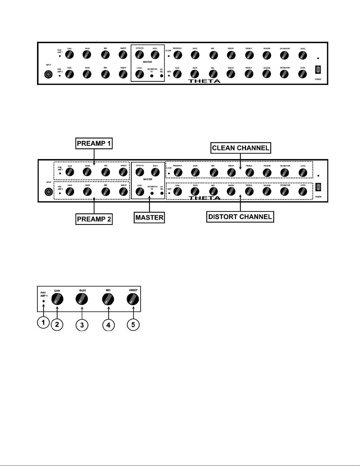
FRONT PANEL
Understanding the THETA amplifier
THETA PREAMP1
1. PREAMP1 ON LED
This led indicates when PREAMP1 is active and in the signal path. NOTE: The PREAMP1
switch on the FOOTCONTROLLER switches PREAMP1 on and off. PREAMP1 is
functional only when the CLEAN channel is selected. PREAMP1 and PREAMP2 will
automatically switch with the channel selected.
2. PREAMP1 GAIN CONTROL
This control adjusts the amount of gain in the signal path of PREAMP1.
3. BASS
This control adjusts the amount of boost or cut in the low frequency portion of the
spectrum of PREAMP1. The available BASS boost and cut range is +/-15 decibels.
Page 4
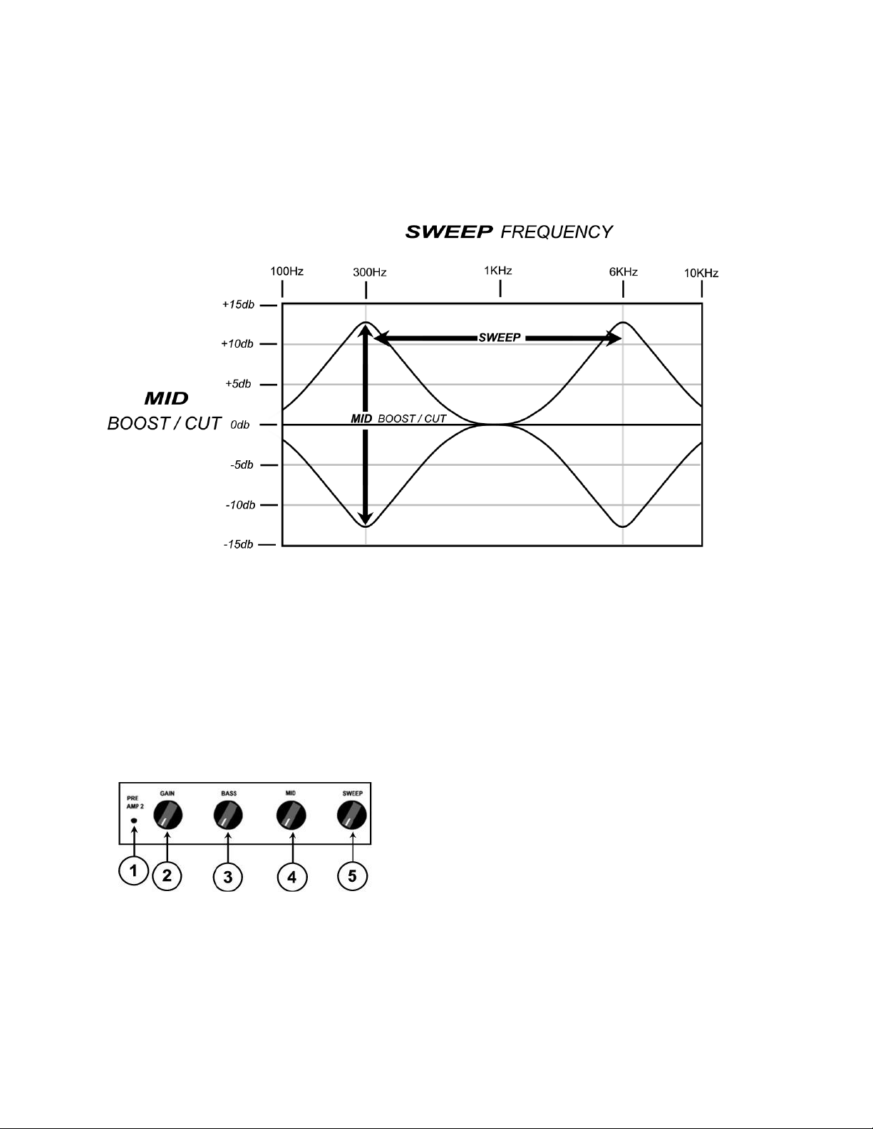
4. MIDRANGE BOOST/CUT CONTROL
This control works in conjunction with the SWEEP frequency control 5. The MID and
SWEEP controls work together to provide a semi-parametric tone control. When the MID
control is set at 12:00 straight up there is no boost or cut in the MID frequency portion of
the spectrum. The graph below shows the response of the MID boost/cut and SWEEP
controls. The MID control allows +/- 12db of boost or cut to be applied at the frequency
determined by the SWEEP control.
5. SWEEP FREQUENCY CONTROL
This control works in conjunction with the MID boost/cut control and adjusts the center
frequency of the MID boost or cut signal. At the full counter clockwise setting the
midrange frequency will be at 300Hz, at the full clockwise setting the center frequency of
the midrange will be at 6KHz. NOTE: when the MID control is set at 12:00 straight up
the SWEEP will not have any affect on the signal since there is not boost or cut being
applied.
THETA PREAMP2
1. PREAMP2 ON LED
This led indicates when PREAMP2 is active and in the signal path. NOTE: The PREAMP2
switch on the THETA FOOTCONTROLLER switches PREAMP2 on and off. PREAMP2 is
functional (active) only when the DISTORT channel is selected. PREAMP2 and
PREAMP1 will automatically switch with the Distort or Clean channel is selected.
NOTE: ALL OF THE REMAINING FUNCTIONS OF PREAMP2 ARE IDENTICAL TO
PREAMP1 AND WILL NOT BE REPEATED.
Page 5

THETA CLEAN CHANNEL
1. CLEAN CHANNEL ON LED
This led indicates when the CLEAN CHANNEL is active. NOTE: The CHANNEL SELECT
switch on the FOOTCONTROLLER switches between the CLEAN CHANNEL and DISTORT
CHANNEL. THE CLEAN can be selected by using either the FOOTCONTROLLER CHANNEL
SELECT switch or by pushing the CHANNEL SELECT switch on the from panel of the
Theta amplifier.
2. PRESENCE CONTROL
This control adjusts the amount of high frequency presence in the CLEAN channel. The
corner frequency of the PRESENCE control is set at 15Khz with a maximum if 15db of
boost.
3. BASS
This control adjusts the amount of boost or cut in the low frequency portion of the
spectrum of PREAMP1. The available BASS boost and cut range is +/-15 decibels.
4. MIDRANGE BOOST/CUT CONTROL
This control works in conjunction with the SWEEP frequency control 5. The MID and
SWEEP controls work together to provide a semi-parametric tone control. When the MID
control is set at 12:00 straight up there is no boost or cut in the MID frequency portion of
the spectrum. The graph below shows the response of the MID boost/cut and SWEEP
controls. The MID control allows +/- 12db of boost or cut to be applied at the frequency
determined by the SWEEP control.
5.
Page 6

SWEEP FREQUENCY CONTROL
This control works in conjunction with the MID boost/cut control and adjusts the center
frequency of the MID boost or cut signal. At the full counter clockwise setting the
midrange frequency will be at 300Hz, at the full clockwise setting the center frequency of
the midrange will be at 6KHz. NOTE: when the MID control is set at 12:00 straight up
the SWEEP will not have any affect on the signal since there is not boost or cut being
applied.
6. TREBLE CONTROL
The TREBLE control adjusts the boost or cut that is applied in the high frequency portion
of the spectrum of CLEAN CHANNEL. The maximum TREBLE boost and cut range is +/15 decibels.
7. REVERB LEVEL CONTROL
The REVERB control adjusts the amount of digital reverb that is added when using the
CLEAN channel. The digital REVERB in the Theta amplifier has a bandwidth of 18KHz
and also includes a digital implementation of the Decimator noise reduction to ensure
that the digital reverb has a dynamic range greater than 110db.
8. DECIMATOR NOISE REDUCTION
The CLEAN channel DECIMATOR control adjusts the threshold of the CLEAN channel
noise reduction. The DECIMATOR noise reduction is a down low level downward
expander incorporating ISP’s patent pending TIME VECTOR PROCESSING.
A BRIEF EXPLANATION OF THE DECIMATOR NOISE REDUCTION SYSTEM
Low Level Downward Expansion is performed by use of a high quality voltage controlled
amplifier controlled by an RMS based audio level detection circuit. A Time Vector
Processing circuit is used which varies the release response over a 1000 to 1 ratio and
controls the release response of the Downward Expander. The release response will be
extremely fast, on the order of 2 milliseconds, if the input signal has a fast decaying
envelope and upwards of 2 seconds if the input signal has a slow decaying signal.
Downward Expansion takes place when the input signal level drops below the preset
threshold. For example: if the threshold is set for 0db and input signal of 0db with
produce no expansion. As the input signal drops below 0db downward expansion starts
and increases exponentially the farther the input signal drops below the threshold point.
The figure below shows the response of the Expander with a 0db threshold.
Page 7

9. LEVEL CONTROL
The LEVEL control adjusts the output LEVEL of the CLEAN channel. NOTE: The final
output level is determined by the setting of the MASTER LEVEL CONTROL.
THETA DISTORT CHANNEL
1. DISTORT CHANNEL ON LED
This led indicates when the DISTORT CHANNEL is active. NOTE: The CHANNEL
SELECT switch on the FOOTCONTROLLER switches between the DISTORT CHANNEL and
CLEAN CHANNEL. THE DISTORT CHANNEL can be selected by using either the
FOOTCONTROLLER CHANNEL SELECT switch or by pushing the CHANNEL SELECT switch
on the from panel of the THETA amplifier.
2. GAIN CONTROL
This control adjusts the amount of gain in the DISTORT CHANNEL. The maximum
amount of gain will be determined by the setting of the DISTORT CHANNEL GAIN and
PREAMP2 gain only if PREAMP2 is switched on. The maximum amount of available gain
is greater than 140db if PREAMP2 is switched on.
3. BASS CONTROL
This control adjusts the amount of boost or cut in the low frequency portion of the
spectrum of the DISTORTION circuit. The available BASS boost and cut range is +/-15
decibels.
4. MIDRANGE BOOST/CUT CONTROL
This control works in conjunction with the SWEEP frequency control 5. The MID and
SWEEP controls work together to provide a semi-parametric tone control. When the MID
control is set at 12:00 straight up there is no boost or cut in the MID frequency portion of
the spectrum. See the graph shown in the CLEAN CHANNEL section, which shows the
response of the MID boost/cut and SWEEP controls. The MID control allows +/- 12db of
boost or cut to be applied at the frequency determined by the SWEEP control.
5. SWEEP FREQUENCY CONTROL
This control works in conjunction with the MID boost/cut control and adjusts the center
frequency of the MID boost or cut signal. At the full counter clockwise setting the midrange
frequency will be at 300Hz, at the full clockwise setting the center frequency of the midrange
will be at 6KHz. NOTE: when the MID control is set at
12:00 straight up the SWEEP will not have any affect on the signal since there is not
boost or cut being applied.
Page 8

6. TREBLE CONTROL
The TREBLE control adjusts the boost or cut that is applied in the high frequency portion
of the spectrum of DISTORTION CHANNEL. The maximum TREBLE boost and cut range
is +/-15 decibels.
7. REVERB LEVEL CONTROL
The REVERB control adjusts the amount of digital reverb that is added when using the
DISTORTION channel. The digital REVERB in the COMBO amplifier has a bandwidth of
18KHz and also includes a digital implementation of the Decimator noise reduction to
ensure that the digital reverb has a dynamic range greater than 110db.
8. DECIMATOR NOISE REDUCTION
The DISTORTION channel DECIMATOR control adjusts the threshold of the CLEAN
channel noise reduction. The DECIMATOR noise reduction is a down low level
downward expander incorporating ISP’s patent pending TIME VECTOR PROCESSING.
Setting the Decimator Noise Reduction System:
Setting the Decimator Threshold for proper use with the Distortion channel is easy if you
follow these instructions. Set the Decimator Threshold full counterclockwise. Adjust the
Distortion gain and Preamp2 gain as desired for your playing. Slowly increase the
Decimator Threshold until the background noise just disappears. This will be the best
possible setting for the Decimator. Increasing the Threshold beyond this point will cause
expansion to be more aggressive than desirable. Some experimentation may be required
to get the best possible Threshold setting.
9. LEVEL CONTROL
The LEVEL control adjusts the output level of the DISTORTION channel. NOTE: The final
output level is determined by the setting of the DISTORTION LEVEL and the MASTER
LEVEL CONTROL.
THETA MASTER CONTROLS
1. LEVEL / MASTER OUTPUT LEVEL
This control determines the master output LEVEL of the THETA
guitar preamplifier.
2. EFFECTS LEVEL CONTROL
This control adjusts the level of an externally connected effects
processor. NOTE: The loop must be turned on via the FOOT
CONTROLLER in order for the EFFECTS level to operate.
3. SOLO LEVEL
This control adjusts the amount of boost that will be applied to the output signal when the
FOOT CONTROLLER boost switch is activated. This control allows the user to switch on and
off via the FOOT CONTROLLER up to 6db of output level boost if desired for soloing
4. DECIMATOR IN/OUT SWITCH
This master DECIMATOR IN / OUT switch activates both the CLEAN channel and
DISTORTION channel DECIMATOR noise reduction systems.
Page 9

5. CHANNEL SELECT SWITCH
The CHANNEL SELECT switch changes the THETA operating channel from CLEAN to
DISTORT. The CHANNEL SELECT switch is a momentary switch that changes the channel
upon pushing the switch. This switch can be used with or without the FOOT CONTROLLER
connected.
BACKPLATE CONTROLS
1. POWER INLET MODULE
This module provides a connection for the power cord.
2. LINE LEVEL OUTPUTS
One ¼” Connection is linked directly to the power amp section and the other ¼” connection
is provided for hookup to the Vector 212 Extension Cabinet.
3. EFFECTS LOOP SEND
Connects to the input of an external effects device
4. EFFECTS LOOP RETURN
Connects to the output of an external effects device
5. FOOTSWITCH
Provides connection to the Theta Foot controller. The THETA FOOT CONTROLLER is
connected using the 15-pin Dsub cable supplied with the THETA.
6. DIRECT OUT
Balanced XLR output for recordings or live performances
Page 10

THETA FOOT CONTROLLER
1. PREAMP1 SWITCH
This switch turns on and off PREAMP1 the CLEAN channel preamp on the THETA.
2. PREAMP1 LED
When this LED in on PREAMP1 is active, switched on.
3. PREAMP2 SWITCH
This switch turns on and off PREAMP2 the DISTORTION channel preamp.
4. PREAMP2 LED
When this LED in on PREAMP2 is active, switched on.
5. CHANNEL SELECT SWITCH
This switch changes the channel selected between CLEAN and DISTORT.
6. CLEAN CHANNEL LED (RED)
This red LED indicates when the CLEAN CHANNEL is on and active.
7. DISTORT CHANNEL LED (BLUE)
This Blue LED indicates when the DISTORTION CHANNEL is on and active.
8. REVERB SWITCH
This switch turns on and off the THETA ‘s internal digital reverb. NOTE: The digital
reverb will only function when the THETA FOOT CONTROLLER is connected and the
reverb circuit is switched on.
9. FX LOOP
This switch turns on and off the external effects loop allowing use of an external effects
processor. NOTE: The FX LOOP will only function when the THETA FOOT CONTROLLER is
connected and the FX LOOP is switched on.
10. BOOST
This switch turns on and off the THETA BOOST function allowing up to 6db of boost of
the output level of the amplifier.
11. D-SUB CONNECTOR
Connect the 15-pin D-SUB connector between this connector and the D-SUB connector
on the back of the THETA amplifier.
Page 11

Power:
Bass Control /Preamp 1 and 2:
Bass Control /Clean and Distort:
Mid Sweep Frequency /Preamps:
Mid Sweep Frequency /Channels:
Mid Boost/Cut Range /Preamps:
Mid Boost/Cut Range /Channels:
Presence Range (Clean Channel):
Decimator Effective Noise Reduction:
Response:
Dimensions:
Weight:
400 watt RMS
+/-15db at 80Hz
+/-15db at 80Hz
300Hz to 6KHz
300Hz to 6KHz
+/-12db
+/-12db
-0db to +18db
Greater than 80db
45Hz at (-10dB)
19” W x 3.5” H x 8” D
4 lbs.
THETA PRE-AMP SPECIFICATIONS
Page 12

WARRANTY AND SERVICE
The Internal Circuitry is fully guaranteed to be free of defects under normal use and
service for a period of two years from the date of purchase. The Speakers and Cabinet that
are used in this product are fully guaranteed to be free of defects under normal use and
service for a period of three years.
Any damage resulting from the misuse or the failure to follow the precautions and
instructions will void the warranty.
In the event that the unit needs to be repaired, please return the unit to ISP
Technologies directly. Simply repack the unit, send a copy of the original receipt, a note
stating the problem, and send it to:
ISP Technologies, LLC
5479 Perry Drive Unit B
Waterford, MI 48329
Attn: Repair Dept.
All shipping charges must be fully prepaid.
ISP will not be responsible for any damages incurred in shipping of any unit. Any claim
will need to be settled with the shipping company.
The warranty will be voided if the serial number has been tampered with in any way.
The warranty card must also be filled out and returned in order to activate the warranty.
Should you have any questions for the repair department prior to returning the product
please call 1-(248)-673-7790
NOTE: This Product may be covered under one or more of the following patents or
patents pending: 7,035,413; 6,944,305; 6,931,134; 6,831,514; 6,091,013
ISP TECHNOLOGIES, LLC
5479 PERRY DRIVE UNIT B
WATERFORD, MI. 48329
248-673-7790
FAX: 248-673-7696
www.isptechnologies.com
 Loading...