

Page 1
1
Page 2
2
IMPORTANT SAFETY INSTRUCTIONS!
Please read this very carefully before operating this unit
Read ALL instructions carefully before using this unit.
Do not operate this unit near water, in the rain or where there is moisture.
If this warning is ignored a serious electrical shock or death may occur.
Do not attempt to service this unit. No user serviceable parts inside. Refer
servicing to qualified, ISP approved service personnel.
Never remove or defeat the ground connection on the power cord of this
unit.
Care should be taken to avoid spilling any foreign objects or liquid into this
unit.
This active speaker system has an internal amplifier and an externally
visible heatsink located on the back of the speaker for cooling of the
internal amplifier. Care should be taken to avoid placing this active
speaker in a location where the external heatsink does not allow proper
cooling of the internal amplifier. Avoid placing this system close to other
heat sources. The external heatsink may reach high temperatures under
normal use. Do not block the external heatsink with any other object.
Make certain there is proper ventilation for the external heatsink when is
use.
Do not drive the SA118 into excessive heavy distortion for an extended
period of time to avoid premature speaker failure.
Failure to follow these instructions may void the warranty.
Page 3
3
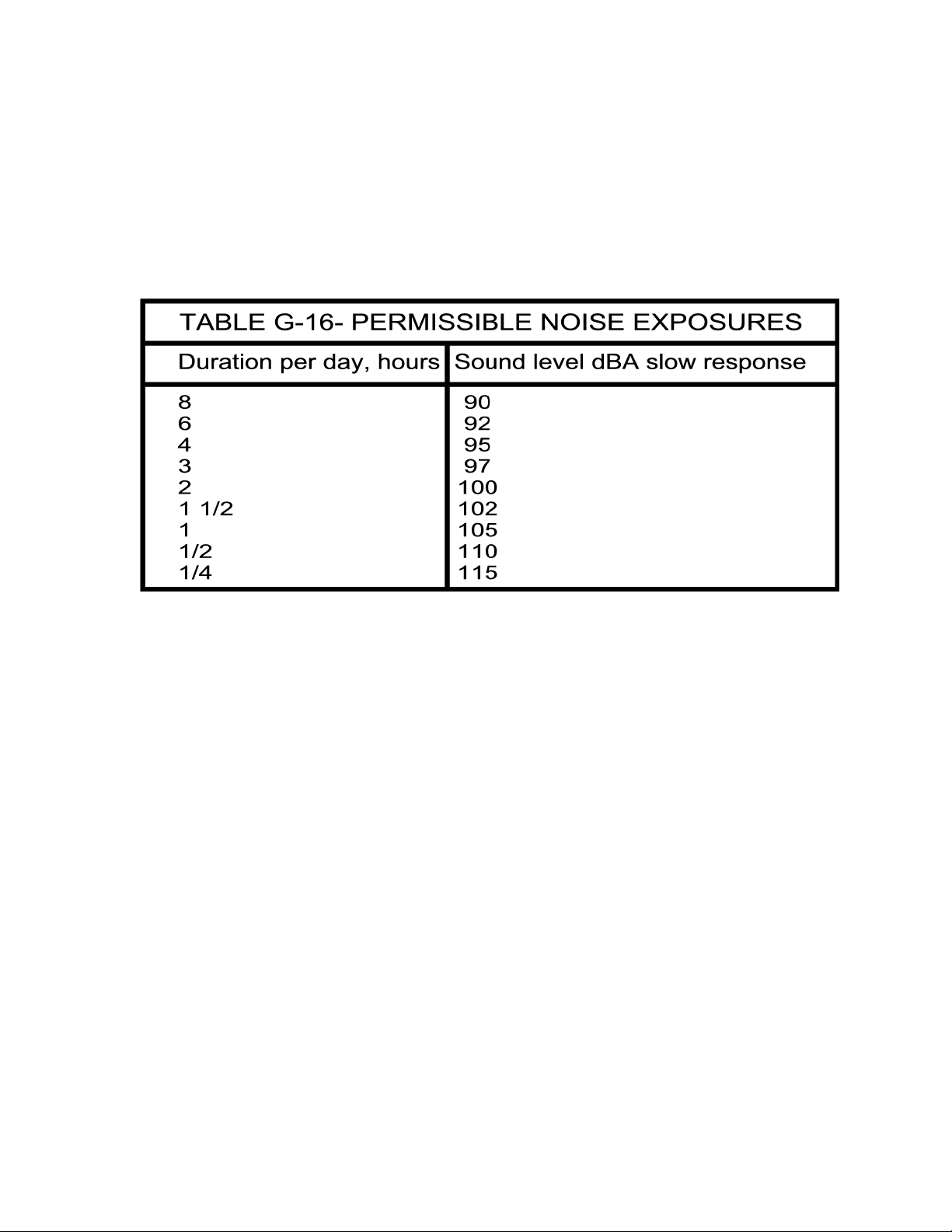
Caution: Exposure to extremely high noise levels can
cause permanent hearing loss.
The SA118 speaker system is capable of producing in excess of 126db SPL at 1 meter.
Continued exposure to noise levels in excess of 90db may cause permanent hearing loss.
Below is a chart of the OSHA (Occupational Safety & Health Administration) regulations for
Occupational Noise Exposure. Please note: OSHA requires hearing protection for any
work environment when the sound levels exceed those shown in Table G-16 when
measured on the A scale of a standard sound level meter at slow response.
INTRODUCTION
Thank you for purchasing ISP Technologies SA118 active subwoofer system. The SA118
is a high output active subwoofer system for high SPL sound reinforcement applications.
The SA118 was designed with a 400-watt 15-inch woofer. The SA118 incorporates a High
Current D-CAT power amplifier system capable of producing upwards of 600 watts RMS
as a stand-alone system. The SA118 can deliver over 900 watts RMS when connected to
one of ISP Technologies passive satellite subwoofers, SP118 or SP115. The amplifier
receives its input signal from an internal fourth order crossover network specifically
designed to provide optimized phase and frequency response for a composite system. The
internal amplifier is based on ISP Technologies patent pending D-CAT (Dynamic Current
Amplifier Technology) amplifier technology. The D-CAT technology is capable of delivering
extremely high output current providing an improvement in transient response, output
current, and a noticeable improvement in PUNCH. The D-CAT amplifier technology utilizes
a monolithic power amplifier driver that reduces parts count and greatly improves reliability.
The D-CAT amplifiers provide improved reliability by including short circuit and over
temperature protection.
The SA118 offers XLR balanced inputs and XLR balanced full range and High Pass
outputs allowing connections for multiple speakers in a system. A sensitivity adjustment
knob allows you to adapt the SA118 speaker for a wide range of common signal levels.
The SA118 subwoofer cabinet is made of high quality 13 ply Baltic birch plywood with a
durable spray on black finish for long life.
Page 4

4
PLACEMENT
The SA118 is designed to sit directly on the floor or stage. Do not position or mount the
cabinet where it can tip over and fall on someone. Do not attempt to mount the cabinet on
speaker stands. Do not attempt to ‘fly’ (suspend by cables, chains, ropes, etc.) the cabinet.
It was not designed for flying. Position it only on a flat, stable surface where it is not in
danger of tipping over.
Also, note that the placement of the cabinet relative to floors and walls will affect the low
frequency response. Placing it closer to the floor and walls will reinforce the low frequency
response. Also, make sure that adequate space (at least 6 inches) is left behind the
cabinet for airflow over the internal amplifier heatsink.
A pole mount socket is provided on the top of the SA118 for mounting one of ISP
Technologies Active Series Tripower 12 or Tripower 12XL three-way speakers. A standard
1-3/8 inch pole is required for mounting the Tripower speakers. To avoid accidents and
insure stability this pole length should not exceed 2 feet in length.
Page 5

5
REAR PANEL DESCRIPTION
1. LEFT HIGH PASS BALANCED OUTPUT- This XLR male connector provides a
balanced high pass output from the left channel input. The high pass frequency
is set at 100 Hz with a 24 dB per octave roll off.
2. RIGHT HIGH PASS BALANCED OUTPUT- This XLR male connector provides
a balanced high pass output from the right channel input. The high pass
frequency is set at 100 Hz with a 24 dB per octave roll off.
3. LEFT FULL RANGE BALANCED OUTPUT- This XLR male connector provides
a balanced full range output from the left channel input. This connector may be
used to daisy-chain the full range signal to additional powered sub cabinets
such as another SA118 or SA115.
4. RIGHT FULL RANGE BALANCED OUTPUT-- This XLR male connector
provides a balanced full range output from the right channel input. This
connector may be used to daisy-chain the full range signal to additional
powered sub cabinets such as another SA 118 or SA115.
5. INPUT PHASE SWITCH- This switch is used to change the polarity of the input
signal going to the power amp of the subwoofer. This will be dependent on the
placement of the Tripower relative to the subwoofer or if another type of
powered cabinet is to be used. The (0) setting (switch out) will make the
subwoofer phase coherent with any of the Tripower series. This switch will not
change the phase of any of the balanced outputs.
6. INPUT SENSITIVITY- This control determines the overall input level of the
signal to the power amp section of the subwoofer cabinet. Adjusting this level
will not affect the level of the signal passing through to the full range or the high
pass outputs.
7. LEFT BALANCED INPUT- This female XLR connector provides an input for the
left channel signal source. This will also feed the left channel signal to the left
high pass and left full range balanced outputs.
8. RIGHT BALANCED INPUT- This female XLR connector provides an input for
the right channel signal source. This will also feed the right channel signal to
the left high pass and right full range balanced outputs.
9. EXTENTION SPEAKER OUTPUT- This Speakon connector provides an output
for a passive extension speaker such as the SP118 or SP115. This will also
increase the power output of the subwoofer amplifier from 600 watts to 900
watts. If another cabinet is to be used other than a SP118 or SP115 as an
extension cabinet, make sure the load of the extension speaker is not less than
4 ohms.
10. POWER SWITCH- This switch provides power to the subwoofer amp section.
Make sure that the input sensitivity control is set to minimum upon power up
11. POWER INLET MODULE- This module provides a connection for the power
cord and also houses the mains fuse. (See Fuse Replacement Section)
Page 6

6
FUSE REPLACEMENT
1. Use a small screwdriver as shown to slide the fuse cover out
from the power inlet module. The fuse can be found inside the
fuse cover module after it is pulled out.
NOTE: A SMALL COMPARTMENT IS ALSO PROVIDED WITHIN THE FUSE COVER
2. After replacing the fuse with another of identical specifications,
MODULE FOR STORING A SPARE FUSE.
push the fuse cover module fully back into place, ensuring that
the fuse has snapped onto the fuse holder inside the power inlet
module.
Page 7

7
CONNECTION DIAGRAM
Page 8

8
The ISP Sub Series has balanced XLR and inputs and outputs configured to AES standards
(Audio Engineering Society). These connections are connected in a loop through configuration
from the inputs to the full range outputs and will accept a balanced line-level input. The
standard phase configuration is that pin 2 is (+), pin 3 is (-), and pin 1 is shielded ground on the
XLR.
Page 9

9
SPECIFICATIONS
System
Frequency Range 30 Hz – 100 Hz
Frequency Response (-3 dB) 38 Hz – 100 Hz
Peak Output @ 1m 126 dB SPL
Crossover Point 100 Hz (24 dB per Octave)
Input Type Balanced differential
Input Impedance 10K ohms
Thermal Protection Output Drivers have internal protection, self resetting. Heatsink
temperature monitored and input is muted if safe temperature is exceeded,
self-resetting. Transformer has internal thermal fuse, self-resetting.
Transducer
Low-Frequency Transducer
Diameter 18” (381mm)
Voice Coil Diameter 4” (76.2mm)
Power Handling 500 watts RMS
D-CAT Technology Power Amplifier
Low-Frequency Amplifier
Power Output / Stand-Alone 600 watts RMS
Power Output with SP118-SP115 900 watts RMS
THD 0.06% typical
Line Input Power
Voltage 117VAC, 60 Hz
Current 6.9 amps
Power 800 watts
Physical
Height 32.5” (825mm)
Front Width 24” (609mm)
Depth 20” (508mm)
Weight 120 lbs.
Enclosure 18mm thick, 13 ply Baltic Birch plywood
Mounting Methods Floor mount
Note: D-CAT is a trademark of ISP Technologies LLC
Page 10

10
THERMAL CONDITIONS
The ISP Sub Series is capable of producing 600 watts at full power to 900 watts using an
extension passive cabinet. This generates heat that must be dissipated in order to maintain
reliability and insure the amplifier components stay within their operating temperature specs. To
accomplish this, the amplifier is mounted onto a heatsink that is exposed on the rear of the
cabinet. Airflow is forced through the fins via the air pressure from the speaker. It is
recommended that the fins have at least 6 inches of clearance from any obstruction to allow
proper ventilation to occur.
In addition, the amplifiers are thermally protected internally via a thermal switch, which will
attenuate the signal 40db when the temperature exceeds a certain point. When the temperature
drops below a certain point, full signal will be restored. Tests have shown under extreme
conditions that cycling will occur (40 sec. ON, 20 sec. OFF).
Under extreme conditions, such as when ambient temperatures are too high (hot rooms,
extreme outdoor temperatures) it is recommended to use a fan on the fins to reduce the cycling
affects.
Page 11

11
WARRANTY AND SERVICE
The Internal Circuitry is fully guaranteed to be free of defects under normal use and service for a
period of three years from the date of purchase. The Speakers and Cabinet that are used in this
product are fully guaranteed to be free of defects under normal use and service for a period of
three years.
Any damage resulting from the misuse or the failure to follow the precautions and instructions
will void the warranty.
In the event that the unit needs to be repaired. Please return the unit to ISP Technologies
directly. Simply repack the unit, send a copy of the original receipt, a note stating the problem,
and send it to:
ISP Technologies, LLC
5479 Perry Dr. Suite B
Waterford, MI. 48329
Attn: Repair Dept.
All shipping charges must be fully prepaid.
ISP will not be responsible for any damages incurred in shipping of any unit. Any claim will need
to be settled with the shipping company.
The warranty will be voided if the serial number has been tampered with in any way.
Should you have any questions for the repair department prior to returning the product please
call 1-(248)-620-6795
NOTE: This Product may be covered under one or more of the following patents or patents
pending: 7,035,413; 6,944,305; 6,931,134; 6,831,514; 6,091,013
NOTE: If it is determined that the power amp module has failed, it is possible for an ISP certified
service center to remove the module from the cabinet by removing the mounting screws and
disconnecting the speaker terminals and the transformer. The module may be sent back to ISP
separately. Please contact ISP for technical support to help determine if the amplifier module
may be defective.
ISP TECHNOLOGIES, LLC
5479 Perry Dr. Suite B
Waterford, MI. 48329
248-673-7790
FAX: 248-673-7696
WWW.ISPTECHNOLOGIES.COM
 Loading...