

Page 1
Page 2

Please read t
IMPORTANT SAFETY INSTRUCTIONS!
his very carefully before operating this unit
Read ALL instructions carefully before using this unit.
Do not operate this unit near water, in the rain, or where there is
moisture. If this warning is ignored a serious electrical shock or death
may occur.
Do not attempt to service this unit. No user serviceable parts inside.
Refer servicing to qualified, ISP approved service personnel.
Never remove or defeat the ground connection on the power cord of
this unit.
Care should be taken to avoid spilling any foreign objects or liquid
into this unit.
Failure to follow these instructions may void the warranty.
Page 3

INTRODUCTION
Thank you for your purchase of the ISP Technologies High Definition Distributed System
CS651 Ceiling Speaker. This product provides a new level of performance in distributed
audio systems allowing greater system flexibility and easy installation of distributed
sound. All connections are made via Cat5 RJ45 connections making installation of
systems faster and easier using the CS651.
PRECAUTIONS
NOTE: IT IS VERY IMPORTANT THAT YOU READ THIS SECTION TO PROVIDE
YEARS OF TROUBLE FREE USE. THIS UNIT REQUIRES CAREFUL HANDELING.
All warnings on this equipment and in the operation instructions should be adhered to and
all operating instructions should be followed.
Do not use this equipment near water. Care should be taken so that objects do not fall
onto and liquids are not spilled into the unit through any openings.
The power cord should be unplugged from the outlet when the unit is left unused for an
extended period of time.
DO NOT ATTEMPT TO SERVICE THIS EQUIPMENT. THIS EQUIPMENT SHOULD BE
SERVICED BY QUALIFIED SERVICE PERSONNELL ONLY. DO NOT MAKE ANY INTERNAL
ADJUSTMENTS OR ADDITIONS TO THIS EQUIPMENT AT ANY TIME. DO NOT TAMPER
WITH INTERNAL ELECTRONIC COMPONENTS AT ANY TIME. FAILURE TO FOLLOW THESE
INSTRUCTIONS WILL VOID THE WARRANTY OF THIS EQUIPMENT, AND MAY CAUSE A
SHOCK HAZZARD.
Page 4

OPERATION
The HDDS Master Control Module is the Master control center for distributed sound
systems using the HDDS technology. The Master Control Module includes six zones
that can be used independently or can be linked to work together allowing the system
designer the flexibility to set up any system with the desired configuration. The
speaker receives power and audio over a Cat5 cable connected to the Master Control
Module, internally converts the AC power to plus / minus 15VDC and 30VDC to power
the amplifier. The audio signal is fed to a precision differential amplifier to remove any
common mode noise, equalized and fed to D-CAT power amplifier circuit to drive both
the woofer and tweeter in the ceiling speaker. The CS651 also allows connection to a
remote level control RM10 allowing user adjustment of the speaker level. By using
remote control RM20 two ceiling speakers can be simultaneously adjusted offering
stereo control. External remote model RM20 allows an external input signal to be
inserted in to the wall mounted Remote such as an IPOD or other external device
connected via a 1/8 inch phone plug. Note: The CS651 ships with a RJ45 Jumper
plug inserted in the Remote Level Port, This jumper is required for audio to
pass if no remote level control is used. If connecting to a RM20 or RM20I
remove this jumper and connect the desired remote level control.
The CS651 is designed for use where non-plenum rated speakers can be used. Dual
slot ports tune the woofer to the enclosure for deep bass reproduction. The CS651
provides a UL94 high temperature rated enclosure. The CS651 speaker includes: a
removable steel mesh grill, built-in mounting brackets, hardware, and installation cutout
template.
Page 5

Rear Panel
1. Remote Level RJ45 Connector
2. Output RJ45 Connector
3. Input RJ45 Connector
4. External Power Adaptor Connector 18VAC 1.5A
The rear panel includes three RJ45 connectors one for input, one for output and one for
connection to an external Remote Level control. The CS651 also includes a power jack
that allows connection to an external 18VAC power adaptor available from ISP
Technologies. Connect the input to the output connector on a HDDS Master Control
Module. A Cat5 cable is used to connect the output connector to another CS651 or to
connect to any other ISP Technologies HDDS powered speaker. Note: The CS651
ships with an RJ45 Jumper plug inserted in the Remote Level Port, This
jumper is required for audio to pass if no remote level control is used. If
connecting to a RM20 or RM20I remove this jumper and connect the desired
remote level control.
Page 6

The power connection on the back of the CS651 can be used to power the speaker as a
stand-alone speaker or can also be used to add additional power if a long run of Cat5
cable is used. When powered a Blue LED will illuminate behind the front grill of the
CS651 indicating the unit is active. The system is designed to allow use of both the
Cat5 cable connected to the HDDS Master Control Module and also an external adaptor
at the same time without risk of damage. The internal power supply will simply derive
power for the power source with the highest voltage available at any point in time.
The CS651 will typically pull less than 250 milliamps of current from the output of the
Master Control Module when used at typical listening levels. With a typical 5 watts of
power per speaker a maximum of 12 CS651 ceiling speakers can be serially connected
on a single run of Cat5 cable. At maximum output level of 30 watts the CS651 can
pull in excess of 1 amp of current. If the installation requires maximum output power it
is recommended to limit the number of serially connected CS651 speakers on a single
50ft run of Cat5 cable to no more than 5 speakers. With longer runs of cable the total
number of CS651 ceiling speakers needs to be reduced in order to achieve a full 30
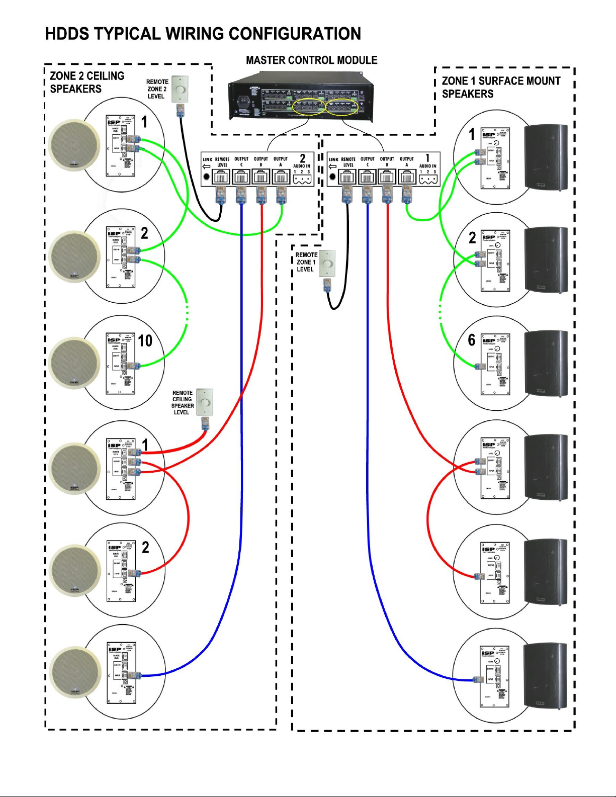
watts continuous output power. Connect the CS651 to any of the three A,B or C
outputs on the rear of the HDDS Master Control Module as shown above.
SPEAKER POWER
The HDDS system distributes low voltage Alternating Current over the Cat5 cable plus
high level balanced audio and is capable of greater than 30 watts continuous power per
speaker. With a typical power per speaker of 10 watts each speaker will consume on
the order of 400mA, which means that 12 speakers would require 4,800mA of current.
Installed systems that require more output power per speaker simply require that the
number of speakers per output A, B and C be reduced so as not to exceed the
maximum of 7 amps available. The current consumption at full power (30 watt
continuous) will require over 1 Amp of power per speaker. In order to allow the full 30
watts of power where higher output levels are required, the number of speakers per A,
B and C outputs of each zone needs to be limited to a maximum 5. Reducing to 20
watts of power per speaker, a maximum of 8 speakers per output can be connected to
each A, B and C zone output. With longer runs of cable exceeding 150 feet the cable
voltage drop will start to become a design factor. The Cat5 cable will start to limit the
total power capability once you exceed 75 feet of cable. Where maximum power
output is critical a more precise calculation can be done by following the speaker
consumption guide.
Page 7

Cat5 Connections
The figure below shows the connections for each output A, B and C of each zone output
on the Master Control Module and also connections between each CS651 speaker.
Connections are done via standard Cat5 cables where pins 1 through 8 are connected
common to the same pins 1 through 8 at each end. As shown below two wires in the
Cable are used for balanced audio and 6 wires are used for power with two providing
ground and two for each of two 22VAC power signals fed down the cable.
Mounting the CS651
Refer installation to a qualified installation professional to ensure proper mounting to
overhead ceilings.
Speaker Location
To achieve the best performance from the CS651 speakers, it is important to carefully
select the location for installation. The CS651 should be installed no more than 5 feet
center to center to provide proper stereo imaging if used in stereo or to avoid comb
filter issues if used in a mono system. The coverage pattern is 90 degrees by 90
degrees with the CS651 so ceiling height will affect the proper location of multiple
speakers. If installing the CS651 as a Single Point Source Speaker it is recommended to
install the speaker in the center of the room.
Speaker Installation
CAUTION: Be certain that there are no electrical wires, water pipes or
heating ducts in the planned installation area before you start drilling or
cutting into the ceiling.
The CS651 is designed to be installed in the ceiling between the studs. If mounting the
CS651 in a drop ceiling other bracing is recommended.
The CS651 requires a hole cutout of 9 5/8 inches for proper clearance. Check the
speaker opening by placing one of the speakers in the hole. The speaker should easily
fit in the opening. Remove the grill on the CS561 with a paper clip or other small tool
that will insert into the small grill holes and pull the grill off. You can also turn the
Page 8

clamps on the back side of the speaker and push downward on the plastic clamp to pop
the front grill off the CS651. Connect the Cat5 input cable and Cat5 output cable if
series connecting multiple speakers. If using the remote level port on the CS651
connect the Cat5 cable to this port at this time. Insert the CS651 into the opening with
the plastic clamps turned in as shown below.
Begin to tighten the installation screws. As you start to turn each screw the Angle Lug
Clamps (A) will rotate outward to engage the ceiling material (C).
CAUTION: Do Not Over Tighten the Clamps. Too much torque may snap off the lug,
causing the speaker not to seat securely. A snug fit is all that is necessary to assure
proper performance.
Remote Level Control
The CS651 allows the use of 3 options for remote level control. If a single CS651
speaker is to be controlled use ISP Technologies RM10 remote level control. The RM10
is designed to control a single Ceiling speaker and requires one Cat5 cable connection
between the CS651 and the RM10. The remote level control will allow adjustment of
the level of the CS651 from zero to the maximum level set on the Master Control
Module. The RM20 allows connection to two CS651 speakers and can control them as a
stereo pair or as dual mono speakers. The RM20i allows connection to two CS651
speakers as above but also includes a 1/8 inch input jack to connect to an iPOD or
other audio device. The figure below shows the connections with two CS651 speakers
and an RM20i Remote Level Control. Note: The CS651 ships with an RJ45 Jumper
plug inserted in the Remote Level Port, This jumper is required for audio to
pass if no remote level control is used. If connecting to a RM20 or RM20I
remove this jumper and connect the desired remote level control.
Page 9
Page 10

HDDS CS651 SPECIFICATIONS
POWER CONSUMPTION: 400 mA typical 1.8 amps Max
POWER WATTS: 30 Watts Maximum
AUDIO INPUT: Balanced 50k input impedance
LEVEL CONTROL PORT: Cat5 RJ45 Connection / Unbalanced
WOOFER: 6.5 inch paper cone
TWEETER: 1 inch Mylar
COVERAGE: 90 Vertical x 90 Horizontal
FREQUENCY RESPONES: 60Hz – 20Khz
WEIGHT: 5LBS
DIMENSIONS: 11” Dia x 7” D
CUTOUT SIZE: 9 5/8 Inches
Page 11

WARRANTY AND SERVICE
The unit, parts and workmanship are fully guaranteed to be free of defects under
normal use and service for a period of 3 years from the date of purchase.
Any damage resulting from the misuse or the failure to follow the precautions and
instructions will void the warranty.
In the event that the unit needs to be repaired, please return the unit to ISP
Technologies directly. Simply repack the unit, send a copy of the original receipt, a
note stating the problem, and send it to:
ISP Technologies, LLC
5479 Perry Drive Unit B
Waterford, MI 48329
Attn: Repair Dept.
All shipping charges must be fully prepaid.
ISP will not be responsible for any damages incurred in shipping of any unit. Any claim
will need to be settled with the shipping company.
The warranty will be voided if the serial number has been tampered with in any way.
The warranty card must also be filled out and returned in order to activate the
warranty.
Should you have any questions for the repair department prior to returning the product
please call 1-(248)-673-7790
NOTE: This Product is covered under one or more of the following patents with other
patents pending: 7,035,413; 6,944,305; 6,931,134; 6,831,514; 6,091,013
ISP TECHNOLOGIES, LLC
5479 PERRY DRIVE SUITE B
WATERFORD, MI. 48329
248-673-7790
FAX: 248-673-7696
WWW.ISPTECHNOLOGIES.COM
 Loading...