

Page 1
Page 2

INTRODUCTION
The Beta Bass Processor offers the professional bassist the highest level of performance that only ISP
Technologies can provide. By incorporating our patented Time Vector Processing, the compression
circuitry becomes the most adaptive to be used in a bass processor as it allows the Beta to truly track the
signal of the exact notes played. Add in the patented Decimator Noise Reduction Technology, and you
have the only bass processor on the market with built in noise reduction! With two parametric bands (a
low mid and a high mid), bass, treble, bright and an exciter (for phase manipulation), the Beta lets you
shape your sound to your own specifications. For unsurpassable performance, pair the Beta Bass with
the ISP Technologies Bass Vector or Bass Vector Pro cabinets and get up to 4000 watts of bass
depending on your choice of configuration!
Please read this manual carefully for a full explanation of the Beta Bass Processor and its functions.
PRECAUTIONS
NOTE: IT IS VERY IMPORTANT THAT YOU READ THIS SECTION TO PROVIDE
YEARS OF TROUBLE FREE USE. THIS UNIT REQUIRES CAREFUL HANDLING.
All warnings on this equipment and in the operation instructions should be adhered to and
all operating instructions should be followed.
Do not use this equipment near water. Care should be taken so that objects do not fall
onto and liquids are not spilled into the unit through any openings.
The power cord should be unplugged from the outlet when the unit is left unused for a long
period of time.
DO NOT ATTEMPT TO SERVICE THIS EQUIPMENT. QUALIFIED SERVICE PERSONNEL
SHOULD SERVICE THIS EQUIPMENT ONLY. DO NOT MAKE ANY INTERNAL ADJUSTMENTS
OR ADDITIONS TO THIS EQUIPMENT AT ANY TIME. DO NOT TAMPER WITH INTERNAL
ELECTRONIC COMPONENTS AT ANY TIME. FAILURE TO FOLLOW THESE INSTRUCTIONS
WILL VOID THE WARRANTY OF THIS EQUIPMENT, AND MAY CAUSE A SHOCK HAZZARD.
POWER REQUIREMENTS
This unit accepts power from the 9V AC power adaptor supplied with the unit. This 9V RMS
AC voltage is internally processed by a voltage doubler, which generates a bi-polar + and –
15V power supply to maintain the headroom and sound quality of professional, studio
quality equipment. Using an external power source minimizes excessive noise and hum
problems often associated with internal transformers, providing optimal performance for the
user.
Page 3
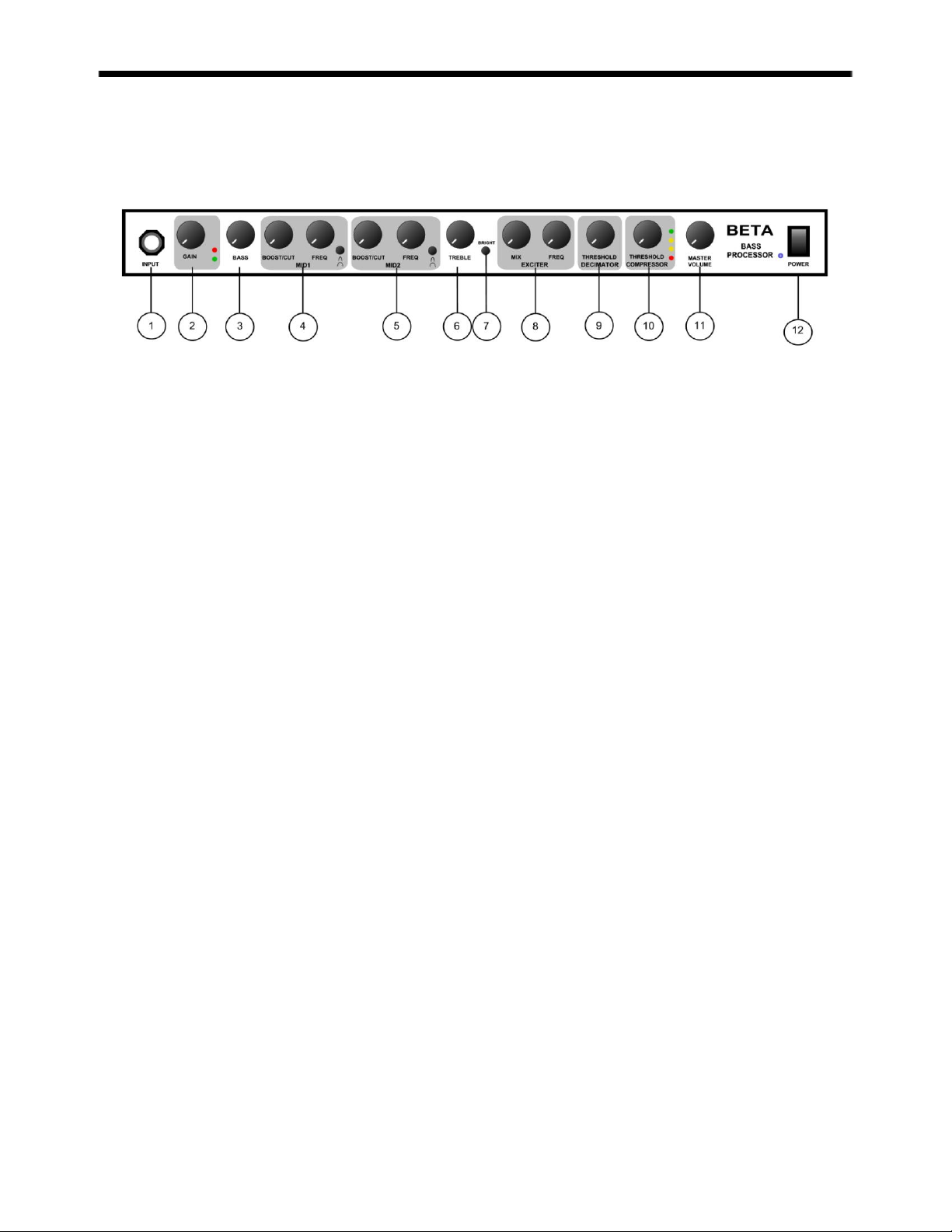
FRONT PANEL
1. INPUT JACK
This ¼-inch mono jack provides the high impedance for connection to your bass.
2. GAIN
Adjust gain until the red LED barely flashes.
3. BASS
Controls the low frequency level.
4. MIDRANGE 1
Controls the low/midrange. BOOST/CUT controls the level at the frequency selected by the FREQ
control. Bandwidth switch selects wide/narrow bandwidth.
5. MIDRANGE 2
Controls the high/midrange. BOOST/CUT controls the level at the frequency selected by the FREQ
control. Bandwidth switch selects wide/narrow bandwidth.
6. TREBLE
Controls the high frequency level.
7. BRIGHT SWITCH
Adds extra high frequency boost.
8. EXCITER
Adds high frequency transparency by altering the harmonic structure.
9. DECIMATOR NOISE REDUCTION THRESHOLD
Controls the level at which the noise reduction takes effect.
10. COMPRESSOR THRESHOLD
Controls the level at which the compressor takes effect.
11. MASTER VOLUME
Controls the level of the main outputs. When the rear panel switch is set to POST, this control will
also affect the level of the direct output.
12. POWER SWITCH
Turns the power on or off.
Page 4

1. 9VAC POWER INPUT JACK
Supplies power to the unit by plugging in a 9V AC adaptor.
2. PRE/POST CONTROL
Controls the source of the DIRECT OUTPUT. PRE takes the DIRECT OUTPUT before the MASTER
VOLUME control and POST takes the DIRECT OUTPUT after the MASTER VOLUME control.
3. GROUND LIFT CONTROL
Disconnects the ground pin (#1) of the DIRECT OUTPUT. This is useful for solving hum
problems.
4. DIRECT LEVEL CONTROL
Controls the level of the DIRECT OUTPUT.
5. DIRECT OUT
Use this output to feed a mixing console.
6. MAIN OUT (XLR)
Use this output to feed the active speaker cabinets.
7. MAIN OUT (1/4 inch)
Use this output to feed the active speaker cabinets.
8. FOOTSWITCH (1/4 inch TRS)
The tip controls the EXCITER on/off and the ring controls the COMPRESSOR on/off.
9. SEND (1/4 inch)
Connect to the input of an external Effects device.
10. RETURN (1/4 inch)
Connect to the output of an external Effects device.
11. EFFECTS LEVEL
Controls the level of the external effect.
REAR PANEL
Page 5

When properly used, the Decimator should be completely transparent; it should have
no effect on the audio signal other than to remove the background noise. To maximize
the performance of the Decimator, it is necessary to understand both the operation of
the controls and the principles of how the internal circuit operates. After this
understanding, it will be easier to set up the Decimator to suit any application.
Low Level Downward Expansion is performed by use of a high quality voltage
controlled amplifier controlled by an RMS based audio level detection circuit. A second
Time Vector Processing circuit that varies the release response over a 1000 to 1 ratio
controls the release response of the Downward Expander. The release response will be
extremely fast, on the order of 2 milliseconds, if the input signal has a fast decaying
envelope and upwards of 2 seconds if the input signal has a slow decaying signal.
Downward Expansion takes place when the input signal level drops below the preset
threshold. For example: if the threshold is set for 0db and input signal of 0db with
produce no expansion. As the input signal drops below 0db, downward expansion
starts and increases exponentially the farther the input signal drops below the threshold
point. The graph below shows the response of the Expander with a 0db threshold.
To set up the Decimator for proper operation first determine the reference level of the
system that the Decimator will be connected to. Most professional products operate at
a +4dbu reference level. Music equipment typically operates at –10dbu. Once the
proper reference level is determined, set the reference level switch on both channels
accordingly.
Page 6

Start by setting the Threshold for minimum, full
counterclockwise. Turn the Threshold control clockwise
until the desired effect of the downward expander is
achieved. The expander should start to operate when
there are gaps in the audio or as the input signal gets
close to the noise floor. NOTE: Setting this control to
high will cause the expander to start to cut off the input
signal to soon.
Input Impedance
Maximum Input Level
Maximum Output Level
Bass Treble Cut Boost Level
Low/Mid parametric frequency
range
High/Mid parametric frequency
range
Compression Section
Decimator Noise Reduction
Power Requirements
Current Draw
Dimensions
500K ohms
+20dbu typical
+20dbu typical
+/- 15db
60Hz-1kHz
200Hz-6kHz
Based on Time Vector Processing
adaptive response auto makeup
gain
Greater than 80db
9V AC 1000ma
865mA
19” x 6” x 1¾”
SETTING THE DECIMATOR THRESHOLD
SPECIFICATIONS
Page 7

WARRANTY AND SERVICE
The unit, parts and workmanship are fully guaranteed to be free of defects under
normal use and service for a period of 3 years from the date of purchase.
Any damage resulting from the misuse or the failure to follow the precautions and
instructions will void the warranty.
In the event that the unit needs to be repaired, please return the unit to ISP
Technologies directly. Simply repack the unit, send a copy of the original receipt, a
note stating the problem, and send it to:
ISP Technologies, LLC
5479 Perry Drive Unit B
Waterford, MI 48329
Attn: Repair Dept.
All shipping charges must be fully prepaid.
ISP will not be responsible for any damages incurred in shipping of any unit. Any claim
will need to be settled with the shipping company.
The warranty will be voided if the serial number has been tampered with in any way.
The warranty card must also be filled out and returned in order to activate the
warranty.
Should you have any questions for the repair department prior to returning the product
please call 1-(248)-673-7790
NOTE: This Product may be covered under one or more of the following patents or
patents pending: 7,035,413; 6,944,305; 6,931,134; 6,831,514; 6,091,013
ISP TECHNOLOGIES, LLC
5479 PERRY DRIVE SUITE B
WATERFORD, MI. 48329
248-673-7790
FAX: 248-673-7696
WWW.ISPTECHNOLOGIES.COM
 Loading...