


 Loading...
EZ Series 42 & EZ Series DR (DR.PTAC)
42” W x 16” H PTAC/PTHP
Perfect fit for Replacing Existing 42” x 16” Units and for New
Construction Projects
AHRI Certification applicable to EZ42 models only
ENGINEERING MANUAL
MA N U FAC T U R E R O F Q UA L I T Y A I R CO N D I T I O N I N G A N D H E AT I N G P R O D U C TS
6140207 Rev. 052019

TABLE OF CONTENTS
Introduction................................................................ |
1 |
Applications................................................................... |
2 |
New Construction....................................................................... |
2 |
Retrofit/Replacement.................................................................. |
2 |
Application Considerations........................................................ |
3 |
Guaranteed Quality..................................................................... |
3 |
Indoor Air Quality - DR. PTAC (EZDR Series Units Only).. |
3 |
Product Overview...................................................... |
4 |
Quiet Operation........................................................................... |
4 |
Durable Construction................................................................. |
4 |
Seacoast Construction................................................................ |
4 |
Chassis Features and Benefits.............................. |
6 |
Slide Out Chassis......................................................................... |
6 |
Wall Sleeve.................................................................................... |
6 |
Exterior Louver/Grilles –............................................................ |
6 |
Removable Front Panel............................................................... |
6 |
Discharge Grille........................................................................... |
6 |
Tangential Blower Wheel............................................................ |
7 |
Slinger Fan.................................................................................... |
7 |
Venturi Shroud............................................................................. |
7 |
Return Air Filters......................................................................... |
7 |
Fresh Air Vent.............................................................................. |
7 |
Ordering Data - EZ Series 42..................................... |
8 |
Model Nomenclature.................................................................. |
8 |
Replacement Guide..................................................................... |
8 |
Performance Data - EZ Series 42............................ |
9 |
Performance Data for EZ42 Series............................................ |
9 |
Heating options............................................................................ |
9 |
Electrical....................................................................................... |
9 |
Ordering Data - EZ Series DR (DR.PTAC)............... |
10 |
Model Nomenclature.................................................................. |
10 |
Replacement Guide..................................................................... |
10 |
Performance Data - EZ Series DR (DR.PTAC)...... |
11 |
Performance Data for EZDR Series.......................................... |
11 |
Heating options............................................................................ |
11 |
Electrical....................................................................................... |
11 |
Dr. PTAC Features......................................................... |
12 |
Dr.PTAC information................................................. |
13 |
Dimensional drawings............................................. |
14 |
Options and Accessories......................................... |
15 |
Hard Wire Kit............................................................................... |
15 |
Remote Control............................................................................ |
15 |
Optional 2 Stage Heater.............................................................. |
15 |
Condensate Drain Kit................................................................. |
15 |
Subbase.......................................................................................... |
15 |
Lateral Duct Kit Assembly.......................................................... |
15 |
Clearances and Projections................................. |
16 |
Installation Instructions..................................... |
17 |
Wall Sleeve Installation Instructions.......... |
18 |
Preparing the Wall Opening...................................................... |
18 |
Framing......................................................................................... |
18 |
Wall Sleeve Installation............................................................... |
19 |
Condensate Drain Kit............................................... |
20 |
Condensate Drain Kit................................................................. |
20 |
External Drain Installation......................................................... |
20 |
Internal Drain Installation.......................................................... |
21 |
Rear Grille Installation Instructions........... |
22 |
Stamped Rear Grille.................................................................... |
22 |
Architectural Rear Grille............................................................ |
23 |
Subbase Assembly & Installation............................................... |
26 |
Subbase Assembly & Installation......................... |
26 |
Chassis Installation.................................................. |
28 |
Front Cover Installation & Removal............... |
29 |
Front Cover Removal.................................................................. |
29 |
Fresh Air Vent................................................................ |
30 |
Fresh Air Vent.............................................................................. |
30 |
Lateral Duct Kit........................................................................... |
30 |
Maintenance.................................................................. |
31 |
Air Intake Filters.......................................................................... |
31 |
Routine Maintenance.................................................................. |
31 |
Information for Heat Pump units...................... |
32 |
Heat Pump Features.................................................................... |
32 |
Electrical Installation.......................................... |
33 |
Hardwire Kit................................................................................. |
33 |
LCDI Cords.................................................................................. |
33 |
PTAC Wire Harness Kit.............................................................. |
33 |
Heaterless Units........................................................................... |
33 |
Voltage Measurements................................................................ |
33 |
Wiring Diagram............................................................ |
34 |
System Controls and Management.................... |
35 |
User Interfaces.............................................................................. |
35 |
Remote Control............................................................................ |
35 |
Digital Control Panel.................................................................. |
35 |
Wall Thermostats......................................................................... |
35 |
Front Desk Control...................................................................... |
35 |
System Management Software................................................... |
36 |
Fan Cycle Control........................................................................ |
36 |
Room Freeze Prevention............................................................ |
36 |
High Temperature Compressor Protection.............................. |
36 |
Low Temperature Compressor Protection............................... |
36 |
Diagnostic Software..................................................................... |
36 |
Custom Operation and Continual Room Temperature |
|
Monitoring................................................................................... |
36 |
Digital Control Panel.............................................. |
37 |
Control panel............................................................................... |
37 |
Power Control.............................................................................. |
37 |
Display........................................................................................... |
37 |
Mode Control - Cool, Fan, and Heat........................................ |
37 |
Fan Speed Control - Low, High, and Auto............................... |
38 |
Temperature Controls................................................................. |
38 |
Operating Guidelines.................................................................. |
38 |
Remote Thermostats................................................. |
39 |
Remote Thermostat Control...................................................... |
39 |
Wireless Wall Thermostat........................................................... |
39 |
Energy Saving Options............................................................... |
39 |
Remote Thermostat Interface............................. |
40 |
Control Board............................................................. |
41 |
Temperature Limiting............................................... |
42 |
Set Temperature Limiting........................................................... |
42 |
Error Codes.................................................................... |
43 |
Diagnostic & Error Codes.......................................................... |
43 |
Packaged Terminal Cooling Unit with Heat Pump or |
|
Electric Heating.......................................................................... |
44 |
Performance Specifications................................. |
44 |
Warranty......................................................................... |
52 |
Islandaire reserves the right to make changes in design and construction at any time without notice.
ManufacturerofQualityAirConditioningandHeatingProducts•www.islandaire.com•sales@islandaire.com•(800)-886-2759
B

INTRODUCTION
OUR COMPANY
Islandaire is the fastest growing specialty air conditioning and heating manufacturer in the country. Founded in 1992 by Robert Hansen, it has grown into a multi-million dollar company in just a few short years.
Islandaire builds a full complement of high quality thru-the-wall replacement air conditioners and heat pumps, water source heat pumps, and gas units in St. James, New York. Each model fits perfectly into the existing original wall case assembly, thereby saving both time and money during installations.
Our Engineering, Production, Sales and Customer Service departments have been fully integrated to provide the maximum degree of user satisfaction. We at Islandaire feel that this team approach to manufacturing produces a
superior overall product and assures a larger degree of flexibility in design and production scheduling to meet tight prototyping or construction timetables.
THE PERFECT FIT
Thru-wall air conditioners were developed in the late 1950’s. Over the next forty years many companies engineered, manufactured and installed a variety of different units throughout the United States and Canada. Today, a number of these companies are no longer in business, or have discontinued their line of thru-wall air conditioners and no longer carry replacement parts.
Islandaire offers replacement air conditioners and heat pumps that are interchangeable with units no longer available from the original manufacturer. Our units are engineered to fit perfectly within the existing wall case, thereby reducing installation time and expense. They are manufactured at our modern 75,000 square foot plant on Long Island in New York.
Thank you for considering our products,
The Islandaire Team
ManufacturerofQualityAirConditioningandHeatingProducts•www.islandaire.com•sales@islandaire.com•(800)-886-2759
1

APPLICATIONS
The EZ Series 42 and DR units are designed and manufactured for new construction or the replacement of packaged terminal air conditioning (PTAC) units in an existing building. Our packaged terminal air conditioning (PTAC) units provide year-round comfort control for hotels, motels, apartments, dormitories, shops, nurs-
ing homes, assisted living centers, satellite offices, room additions and other applications that require economical heating and cooling.
The product is designed for individually-zoned, comfortcontrolled, heating and cooling. The unit width is an industry standard 42”. We offer our cooling chassis to operate with cooling only or electric heat. The design standards, heavy duty construction and the focus on indoor noise reduction has created our unit as the premier unit of the future. Individually controlled PTAC units are ideal for rooms that are not occupied during vacancies, holidays, weekends or nights. Individual units allow tenants to choose the degree of comfort and operating economy.
Thermostat and fan controls are built into the digital touch-pad, plus all units have the flexibility to convert to a wall thermostat control, or interface into energy management systems. Whether you are designing a new structure or replacing PTAC units in an existing building, Islandaire will meet your needs.
NEW CONSTRUCTION
The Islandaire EZ42 and EZDR Packaged Terminal Air Conditioning (PTAC) unit is designed to meet the needs of the architect, engineer, and contractor. For unit installation, Islandaire’s expert support network will assist in all applicable aspects of the construction project, from preparing a budget to start-up.
ADVANTAGES FOR NEW CONSTRUCTION
Design Flexibility For The Architect Engineer
•Super-quiet performance, indoors and out
•No bulky duct system
•No separate equipment room
•No water towers or additional cooling equipment
•Less sensitivity or building orientation
•Optional architectural grille to permit custom exterior appearance
Lower Operating Costs & Reliable Comfort for the Occupant
Islandaire helps lower utility costs with energy efficient units that exceed industry standards. Energy savings are achieved in both heating and cooling environments through efficient mechanical design and onboard electronic logic. Separate indoor and outdoor fans provide lower operating costs. Energy management software is built into the unit’s standard digital controls.
These units may also qualify for electrical power company rebates. (Consult your local utility provider for rebate opportunities.)
RETROFIT/REPLACEMENT
Islandaire PTAC units are engineered to fit perfectly within most existing wall sleeves, thereby reducing installation time and expense. There is no time wasted on redesigning an existing wall opening or removing an old wall sleeve. Just slide the old chassis out and replace with a new one from Islandaire.
EZ Quick slide-out chassis eases installation into the wall sleeve. Rapid servicing reduces downtime: complete chassis can be replaced in minutes without disrupting other occupants.
ManufacturerofQualityAirConditioningandHeatingProducts•www.islandaire.com•sales@islandaire.com•(800)-886-2759
2

APPLICATIONS (cont.)
APPLICATION CONSIDERATIONS
It is important for air conditioning systems to be properly sized for each application in order to achieve desired temperature and humidity levels. It is strongly recommended that a professional engineer match the PTAC units with the building structure and climate.
The following application considerations are all important in choosing the proper PTAC system for the building structure.
UNDERSIZING
If a PTAC unit is undersized (cooling capacity is less than required capacity for an application), the unit will not be able to cool the space down to the desired temperature during very hot days.
OVERSIZING
If a PTAC unit is oversized (cooling capacity is greater than required capacity for the specific application), the unit will cool the space down to the desired temperature too quickly creating a cool, yet excessively humid, space.
AIR INFILTRATION
Excessive air infiltration can intensify problems associated with undersizing or oversizing a PTAC unit. This can be the cause of insufficient cooling, dehumidification, or heating. Sources of air infiltration include vents, gaps around windows and doors, and improperly sealed floors, ceiling or wall joints.
GUARANTEED QUALITY
Each Islandaire unit is designed to operate quietly and efficiently and is backed by the best warranty program available. Standard warranty is one year parts and labor including five year compressor part only warranty or two year parts only including five year compressor part only warranty.
Whether it is an exact replacement unit or a new construction project, Islandaire is the smart choice for all your air conditioning and heating needs.
INDOOR AIR QUALITY - DR. PTAC (EZDR SERIES UNITS ONLY)
In addition to an already quiet unit, we have co-developed an indoor air quality option called Dr.PTAC.
Dr.PTAC is currently designed as a two-stage system. The primary stage conditions room air and tempers the air to acceptable air quality levels. The secondary stage brings in conditioned outside air at a rate of up to 55 CFM, to compensate for toilet exhaust and room
occupancy, and continuously pressurizes the room. The secondary stage is initiated by an outdoor humidistat that allows the unit to condition the incoming fresh air about 50% RH. The system can be calibrated to run at higher outdoor RH levels, but the recommended maximum set point 50% outdoor RH. When outdoor RH levels are above the set point, the secondary compressor is initiated and conditions make up air below the set point.
The secondary fan continuously runs allowing fresh, conditioned, make-up air at a rate of up to 55 CFM (leaving coil CFM) to enter the room. The unit is manufactured in accordance to ARI, UL, CSA standards for the primary side and AHAM and UL standards for the secondary side.
ManufacturerofQualityAirConditioningandHeatingProducts•www.islandaire.com•sales@islandaire.com•(800)-886-2759
3

PRODUCT OVERVIEW
QUIET OPERATION
The cross-flow tangential fan wheel design used in our EZ42 and EZDR units provide whisper quiet operation while delivering maximum airflow required for proper air circulation. Separate indoor and outdoor fan motors further reduce operating sound levels and costs.
The heavy gauge construction of the chassis and cabinet minimizes vibration for quieter operation. Vibration isolators on the rotary compressor keep it running smoothly and quietly. The unit bulkhead is fully insulated to decrease outdoor sound transmission.
The compressor is isolated to minimize vibration and sound transmission for quiet operation.
DURABLE CONSTRUCTION
•Islandaire PTAC/PTHP units are built with durable, quality components designed for continuous operation in all environments.
•Our wall sleeves are constructed of thick 18-gauge steel with a tough baked-on finish for maximum durability.
•The outdoor fan motor is totally enclosed, preventing damage from moisture and debris introduced by extreme weather conditions. Both indoor and outdoor fan motors are permanently lubricated for extended life.
•Electrical components are located on the indoor side of the wall protecting them from driving rain and humidity.
•The compressor is a reliable, high efficiency design rotary compressor. It is hermetically sealed and designed for continuous operation.
•Repositionable discharge grille allows angle of airflow to be adjusted according to application. Made from tough plastic material that won’t rust, resists scratches and is easy to clean.
SEACOAST CONSTRUCTION
Application of air conditioning equipment in a corrosive environment requires special consideration. The corrosive nature of salt water vapor, chlorine and acid vapor, demands a unit that can withstand these environments. Any metal portion that is exposed to a corrosive vapor must be specially treated.
All Islandaire PTAC units have special corrosion protection that can help dramatically extend the life of the unit. Listed below are just some of the components that feature corrosion protections:
•Wall Sleeve – The entire wall sleeve is constructed of 18-gauge steel. Treated inside and outside with a baked-on based powder coat paint to protect it from the corrosive effects of salt spray.
•Base Pan – Base pan has a corrosion resistant coating to protect it from the elements.
•Condenser Coil – Protective coating applied to the coil to prevent corrosion and weathering.
•Condenser Fan Blade – Constructed of strong engineering plastic that has excellent flame resistance and dimensional stability over a wide range of service temperatures.
•Condenser Fan Motor – Specially coated by the manufacturer.
•Compressor – Protective coating applied by the manufacturer on the exterior to enhance equipment life and performance.
•Outdoor Louver – Made of aluminum, etched and anodized for maximum corrosion protection. Available in stamped or architectural styles. Can be painted in a wide choice of colors.
Standard on All Models:
Corrosion protection treatment shields the EZGS unit from corrosive environments and extends the life of the unit, especially in coastal locations.
ManufacturerofQualityAirConditioningandHeatingProducts•www.islandaire.com•sales@islandaire.com•(800)-886-2759
4

PRODUCT OVERVIEW (cont.)
Islandaire manufactures the EZ42/EZDR loaded with standard features that other manufacturers often consider optional.
VENTURI SHROUD
SLINGER FAN BLADE
TANGENTIAL BLOWER WHEEL
DISCHARGE GRILLE
WALL SLEEVE
RETURN AIR
FILTERS
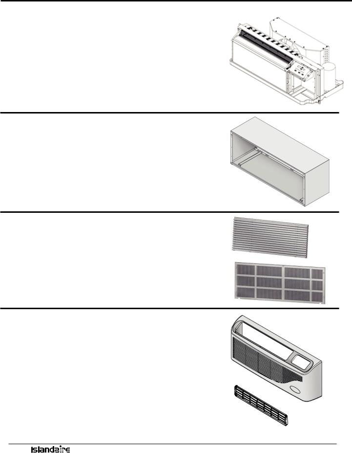
CHASSIS
AUTO
REMOVABLE FRONT PANEL
DIGITAL TOUCHPAD CONTROL /
DIAGNOSTIC CENTER
COMPRESSOR
FRESH AIR INTAKE
SLOPED BASEPAN
ManufacturerofQualityAirConditioningandHeatingProducts•www.islandaire.com•sales@islandaire.com•(800)-886-2759
5
CHASSIS FEATURES AND BENEFITS
SLIDE OUT CHASSIS
•Slide-out chassis makes installation simple
•All components are readily accessible to service personnel
•On-board diagnostic software and display help diagnose potential problems
•Designed to replace older units with minimal modification
•Isolated rotary compressor design for continuous efficient, reliable and quiet operation
See page 28 for chassis installation instructions
WALL SLEEVE
Part Number 2401135-00
•Thick insulation on the top and sides to reduce noise and increase efficiency
•Heavy 18 gauge steel with powder paint coating for maximum scratch, dent and corrosion resistance
See page 19 for wall sleeve installation instructions
EXTERIOR LOUVER/GRILLES –
•Architectural extruded aluminum grille, Part Number 6070422
•Custom colors available (Ask for our color chart sheet)
•Stamped Grille, Part Number 6070264
See page 22for exterior grille installation instructions
REMOVABLE FRONT PANEL
Part Number 6130133
•Made from durable plastic that won’t rust, resists scratches and is easy to clean
•Quick removal ensures shorter installation time and faster service calls
•Easy access to removable filters
DISCHARGE GRILLE
Part Number 6130134
• Tough ABS plastic is durable, easy to clean and maintain
See page 29 for front cover installation instructions
ManufacturerofQualityAirConditioningandHeatingProducts•www.islandaire.com•sales@islandaire.com•(800)-886-2759
6
CHASSIS FEATURES AND BENEFITS (cont.)
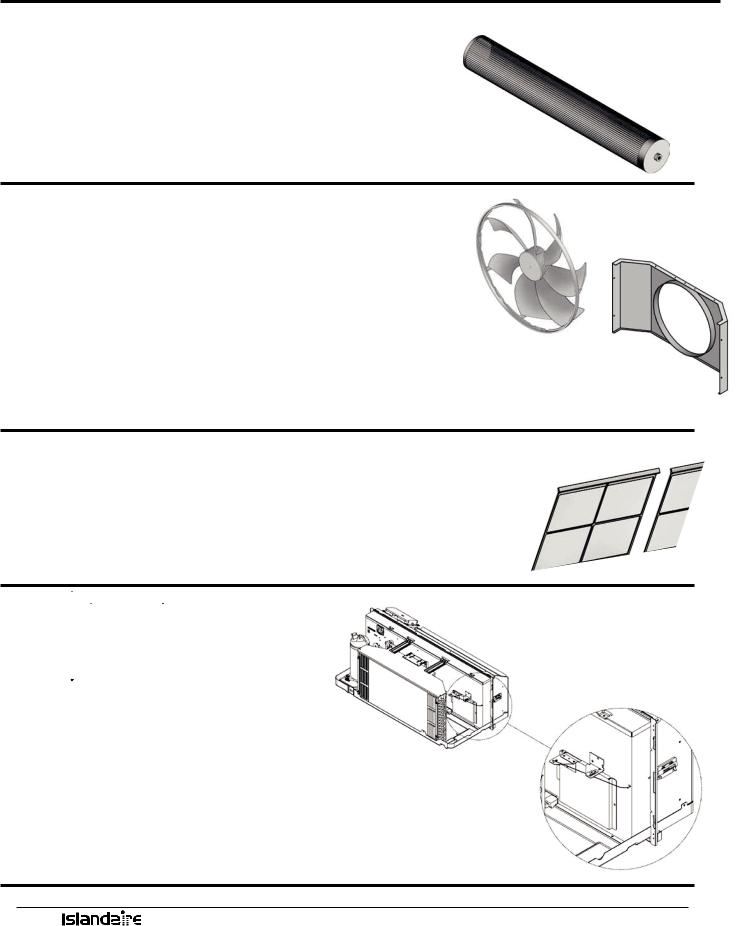
TANGENTIAL BLOWER WHEEL
•Creates extremely quiet indoor operating environment
•Generates a balanced and constant airflow into the room
SLINGER FAN
•Curved fan blades increase airflow across the outside coil
•Creates a quiet operating environment outside of building
•Slinger ring efficiently removes condensate and increases cooling
VENTURI SHROUD
•Works with the fan to maximize air flow and increase efficiency
•Removes easily for quick access when cleaning the condenser coil
RETURN AIR FILTERS
(2 per) Part Number 6080067
•Easily removable from the front of the unit for cleaning
•Filters the circulated air inside the room
•Keeps the system clean and working efficiently
•Clean filters increase life of the system components
See page 39 for maintenance information
FRESH AIR VENT
•Allows fresh air to be drawn into the room when indoor fan is operating
•Manual control allows uninterrupted operation
See page 30 for fresh air vent information
ManufacturerofQualityAirConditioningandHeatingProducts•www.islandaire.com•sales@islandaire.com•(800)-886-2759
7

ORDERING DATA - EZ SERIES 42
MODEL NOMENCLATURE
Please review the nomenclature/model number breakdown below for the EZ Series 42 options.
Units are available in four cooling BTUH sizes:
7,500; 9,500; 12,000; 15,000
Voltage options are: 115V, 208/230V, and 277V.
Control choices include a unit mounted digital control; multiple wired wall mounted heating/cooling thermostats and a wireless wall thermostat, with occupancy sensor control.
|
|
|
|
EZ 42 12 1 2 A 1 S 4 6 A A |
|
|
|
|
|
|
|
|
|||||||||||||||||||||||||
|
COMPONENT |
|
|
|
|
|
|
|
|
|
|
|
|
|
|
|
|
|
|
|
|
|
|
|
|
|
|
FUNCTIONAL OPTIONS |
|||||||||
|
|
|
|
|
|
|
|
|
|
|
|
|
|
|
|
|
|
|
|
|
|
|
|
|
|
|
|
|
|
|
|
|
|
||||
|
EZ-CoolingChassis |
|
|
|
|
|
|
|
|
|
|
|
|
|
|
|
|
|
|
|
|
|
|
|
|
|
|
A-ManualFreshAir |
|
|
|
|
|||||
|
MODEL TYPE |
|
|
|
|
|
|
|
|
|
|
|
|
|
|
|
|
|
|
|
|
|
|
|
|
|
|
B-MotorizedFreshAir |
|
|
|
|
|||||
|
|
|
|
|
|
|
|
|
|
|
|
|
|
|
|
|
|
|
|
|
|
|
|
|
|
|
|
|
|
|
|
|
|
|
|||
|
|
|
|
|
|
|
|
|
|
|
|
|
|
|
|
|
|
|
|
|
|
|
|
|
|
|
|
|
|
|
|
|
|
|
|
|
|
|
42-ISLANDAIRE42X16PTAC |
|
|
|
|
|
|
|
|
|
|
|
|
|
|
|
|
|
|
|
|
|
|
|
|
|
|
|
|
|
|||||||
|
COOLING CAPACITY |
|
|
|
|
|
|
|
|
|
|
|
|
|
|
|
|
|
|
|
|
|
|
|
|
|
|
|
|
|
|||||||
|
|
|
|
|
|
|
|
|
|
|
|
|
|
|
|
|
|
|
|
|
|
|
|
|
|
|
|
|
|
|
|
|
|
|
|
|
|
|
07-7,500BTU |
|
|
|
|
|
|
|
|
|
|
|
|
|
|
|
|
|
|
|
|
|
|
|
POWER |
|
POWER |
||||||||||
|
09-9,500BTU |
|
|
|
|
|
|
|
|
|
|
|
|
|
|
|
|
|
|
|
|
|
|
|
|
||||||||||||
|
12-12,000BTU |
|
|
|
|
|
|
|
|
|
|
|
|
|
|
|
|
|
|
|
|
|
|
|
MANAGEMENT OPTIONS |
|
MANAGEMENT CODES |
||||||||||
|
15-15,000BTU |
|
|
|
|
|
|
|
|
|
|
|
|
|
|
|
|
|
|
|
|
|
|
|
A-None |
|
A-A |
|
|||||||||
|
SYSTEM TYPE |
|
|
|
|
|
|
|
|
|
|
|
|
|
|
|
|
|
|
|
|
|
|
|
C-EnergyMgt.N/O |
|
P-C |
||||||||||
|
1-StandardCooling |
|
|
|
|
|
|
|
|
|
|
|
|
|
|
|
|
|
|
|
|
|
|
|
D-EnergyMgt.N/C |
|
T-D |
||||||||||
|
2-HeatPump |
|
|
|
|
|
|
|
|
|
|
|
|
|
|
|
|
|
|
|
|
|
|
|
|
|
|
|
|
|
|
|
|
|
|
||
|
VOLTAGE / LINE CORD |
|
|
|
|
|
|
|
|
|
|
|
|
|
|
|
|
|
|
|
|
|
|
|
|
|
|
|
|
|
|||||||
|
1-115v,20Amps |
|
|
|
|
|
|
|
|
|
|
|
|
|
|
|
|
|
|
|
|
|
|
|
|
|
|
|
|
|
|
|
|
|
|
||
|
2-230v,20Amps |
|
|
|
|
|
|
|
|
|
|
|
|
|
|
|
|
|
|
|
|
|
|
|
|
|
|
|
|
|
|
|
|
|
|
||
|
3-230v,30Amps |
|
|
|
|
|
|
|
|
|
|
|
|
|
|
|
|
|
|
|
|
|
|
|
|
|
|
IDENTITY CODE |
|
|
|
|
|||||
|
4-230v,JunctionBox |
|
|
|
|
|
|
|
|
|
|
|
|
|
|
|
|
|
|
|
|
|
|
|
|
|
|
|
|
|
|
||||||
|
5-115v,15Amps |
|
|
|
|
|
|
|
|
|
|
|
|
|
|
|
|
|
|
|
|
|
|
|
|
|
|
0-Special |
|
|
|
|
|
||||
|
6-115v,JunctionBox |
|
|
|
|
|
|
|
|
|
|
|
|
|
|
|
|
|
|
|
|
|
|
|
|
|
|
6-Standard |
|
|
|
|
|||||
|
7-277v,20Amps |
|
|
|
|
|
|
|
|
|
|
|
|
|
|
|
|
|
|
|
|
|
|
|
|
|
|
|
|
|
|
|
|
|
|
||
|
8-277v,JunctionBox |
|
|
|
|
|
|
|
|
|
|
|
|
|
|
|
|
|
|
|
|
|
|
|
|
|
|
|
|
|
|
|
|
|
|
||
|
9-230v,15Amps |
|
|
|
|
|
|
|
|
|
|
|
|
|
|
|
|
|
|
|
|
|
|
|
|
|
|
|
|
|
|
|
|
|
|
||
|
F-277v,30Amps |
|
|
|
|
|
|
|
HYDRONIC OPTIONS |
|
ROOM CONTROLS |
|
|
|
|
RETURN DISCHARGE OPTIONS |
|||||||||||||||||||||
|
|
HEATING OPTIONS |
|
|
|
|
|
|
|
|
|
|
|
|
|||||||||||||||||||||||
|
|
|
|
|
|
|
|
|
1-None |
|
|
|
E-WirelessThermostat(typemustbespeci- |
4-FrontRet./TopDis. |
|
|
|
|
|||||||||||||||||||
|
3-DualStage3.4kWElectric |
|
|
|
|
|
|
|
|
|
|
|
|
fiedwhenplacingorder) |
|
|
|
|
|
|
|
|
|
|
|
|
|||||||||||
|
4-DualStage5.0kWElectric |
|
|
|
|
|
|
|
|
|
|
F-WallThermostatInterface,Master |
|
|
|
|
|
|
|
|
|
|
|
|
|||||||||||||
|
7-1.7kWElec.Heat(115vOnly) |
|
|
|
|
|
|
|
|
|
|
G-WallThermostatInterface,Slave |
|
|
|
|
|
|
|
|
|
|
|
|
|||||||||||||
|
A-NoneCoolingOnly |
|
|
|
|
|
|
|
|
|
|
|
|
|
|
|
N-WallThermostatInterface,Std.Elect. |
|
|
|
|
|
|
|
|
||||||||||||
|
B-2.0kWElec.Heat(208v-277v) |
|
|
|
|
|
|
|
|
|
|
Cntrls |
|
|
|
|
|
|
|
|
|
|
|
|
|
|
|
|
|
|
|||||||
|
Y-1.3kWElec.Heat(115vOnly) |
|
|
|
|
|
|
|
|
|
|
S-Std.ElectronicControls(UnitMounted) |
|
|
|
|
|
|
|
|
|||||||||||||||||
REPLACEMENT GUIDE |
|
|
|
|
|
|
|
|
|
|
|
|
|
|
|
|
|
|
|
|
|
|
|||||||||||||||
MANUFACTURER |
|
MODEL |
|
WALL OPENING DIMENSION |
DISCHARGE |
RETURN AIR |
|
HEAT TYPE |
|
|
|||||||||||||||||||||||||||
|
|
|
|
|
16 ¼” x 42 ¼” |
ANGLED |
|
FLAT |
BOTTOM |
|
|
|
FRONT |
|
ELECTRIC |
|
HYDRONIC |
|
|
||||||||||||||||||
|
|
|
|
|
|
|
|
|
|
|
|
|
|
|
|
|
|
|
|
|
|
|
|
|
|
|
|
|
|
|
|
|
|
|
|
|
|
|
|
|
|
AC |
|
|
|
HP |
|
|
|
|
|
|
|
|
|
|
|
|
|
|
|
|
|
|
|
|
|
|
|||||||
|
|
|
|
|
|
|
|
|
|
|
|
|
|
|
|
|
|
|
|
|
|
|
|
|
|
|
|
|
|
|
|
|
|
|
|
|
|
AMANA |
|
PTC |
|
• |
|
|
|
• |
• |
|
• |
• |
|
|
|
|
• |
|
• |
|
|
• |
|
|
|||||||||||||
|
|
|
|
|
|
|
|
|
|
|
|
|
|
|
|
|
|
|
|
|
|
|
|
|
|
|
|
|
|
|
|
|
|
|
|
|
|
CLIMATE |
|
PIP |
|
• |
|
|
|
• |
• |
|
• |
• |
|
|
|
|
• |
|
• |
|
|
• |
|
|
|||||||||||||
MASTER |
|
|
|
|
|
|
|
|
|
|
|
|
|
|
|
|
|
|
|
|
|
|
|
|
|
|
|
|
|
|
|
|
|
|
|
|
|
|
|
PDE |
|
• |
|
|
|
• |
• |
|
• |
• |
|
|
|
|
• |
|
• |
|
|
• |
|
|
|||||||||||||
|
|
|
|
|
|
|
|
|
|
|
|
|
|
|
|
|
|
|
|
|
|
|
|
|
|
|
|
|
|
|
|
|
|
|
|
|
|
MC QUAY |
|
PSE |
|
• |
|
|
|
• |
• |
|
• |
• |
|
|
|
|
• |
|
• |
|
|
• |
|
|
|||||||||||||
|
|
|
|
|
|
|
|
|
|
|
|
|
|
|
|
|
|
|
|
|
|
|
|
|
|
|
|
|
|
|
|
|
|
|
|
|
|
|
|
MQE |
|
• |
|
|
|
• |
• |
|
• |
• |
|
|
|
|
• |
|
• |
|
|
• |
|
|
|||||||||||||
|
|
|
|
|
|
|
|
|
|
|
|
|
|
|
|
|
|
|
|
|
|
|
|
|
|
|
|
|
|
|
|
|
|
|
|
|
|
GREE |
|
ETAC |
|
• |
|
|
|
• |
• |
|
• |
• |
|
|
|
|
• |
|
• |
|
|
• |
|
|
|||||||||||||
TRANE |
|
PTE |
|
• |
|
|
|
• |
• |
|
• |
• |
|
|
|
|
• |
|
• |
|
|
• |
|
|
|||||||||||||
|
|
|
|
|
|
|
|
|
|
|
|
|
|
|
|
|
|
|
|
|
|
|
|
|
|
|
|
|
|
|
|
|
|
|
|
|
|
LG |
|
LP |
|
• |
|
|
|
• |
• |
|
• |
• |
|
|
|
|
• |
|
• |
|
|
• |
|
|
|||||||||||||
|
|
|
|
|
|
|
|
|
|
|
|
|
|
|
|
|
|
|
|
|
|
|
|
|
|
|
|
|
|
|
|
|
|
|
|
|
|
GE |
|
AZ |
|
• |
|
|
|
• |
• |
|
• |
• |
|
|
|
|
• |
|
• |
|
|
• |
|
|
|||||||||||||
|
|
|
|
|
|
|
|
|
|
|
|
|
|
|
|
|
|
|
|
|
|
|
|
|
|
|
|
|
|
|
|
|
|
|
|
|
|
ManufacturerofQualityAirConditioningandHeatingProducts•www.islandaire.com•sales@islandaire.com•(800)-886-2759
8
PERFORMANCE DATA - EZ SERIES 42
PERFORMANCE DATA FOR EZ42 SERIES
MODELS
|
|
EZ07 |
|
|
EZ09 |
|
|
EZ12 |
|
|
EZ15 |
|
|||
|
|
|
|
|
|
|
|
|
|
|
|
|
|
|
|
VOLTS |
230 |
208 |
277 |
115 |
230 |
208 |
277 |
115 |
230 |
208 |
277 |
230 |
208 |
277 |
|
|
|
|
|
|
|
|
|
|
|
|
|
|
|
|
|
BTUH COOL |
7,200 |
6,800 |
7,200 |
9,800 |
9,500 |
9,300 |
9,500 |
12,500 |
12,500 |
12,300 |
12,500 |
14,500 |
14,300 |
15,000 |
|
|
|
|
|
|
|
|
|
|
|
|
|
|
|
|
|
AMPS COOL |
2.46 |
2.52 |
2.11 |
7.22 |
3.41 |
3.70 |
2.83 |
9.30 |
4.65 |
5.05 |
3.86 |
5.96 |
6.49 |
5.20 |
|
|
|
|
|
|
|
|
|
|
|
|
|
|
|
|
|
WATTS COOL |
565 |
525 |
585 |
830 |
785 |
770 |
785 |
1,070 |
1,070 |
1,050 |
1,070 |
1,370 |
1,350 |
1,440 |
|
|
|
|
|
|
|
|
|
|
|
|
|
|
|
|
|
EER |
12.8 |
13.0 |
12.3 |
11.8 |
12.1 |
12.1 |
12.1 |
11.7 |
11.7 |
11.7 |
11.7 |
10.6 |
10.6 |
10.4 |
|
|
|
|
|
|
|
|
|
|
|
|
|
|
|
|
|
CFM HIGH COOL |
375 |
340 |
360 |
340 |
375 |
340 |
360 |
340 |
375 |
340 |
360 |
360 |
360 |
360 |
|
|
|
|
|
|
|
|
|
|
|
|
|
|
|
|
|
CFM LOW COOL/ |
260 |
240 |
260 |
240 |
260 |
240 |
260 |
240 |
260 |
240 |
260 |
260 |
240 |
260 |
|
HEAT |
|||||||||||||||
|
|
|
|
|
|
|
|
|
|
|
|
|
|
||
BTUH HEATING |
6,400 |
6,300 |
6,100 |
8,500 |
8,500 |
8,300 |
8,500 |
11,400 |
11,400 |
11,000 |
11,400 |
13,600 |
13,200 |
14,000 |
|
|
|
|
|
|
|
|
|
|
|
|
|
|
|
|
|
WATTS HEATING |
530 |
520 |
520 |
710 |
700 |
685 |
710 |
980 |
950 |
915 |
980 |
1180 |
1150 |
1300 |
|
|
|
|
|
|
|
|
|
|
|
|
|
|
|
|
|
C.O.P. |
3.54 |
3.55 |
3.44 |
3.51 |
3.55 |
3.55 |
3.51 |
3.40 |
3.52 |
3.52 |
3.40 |
3.38 |
3.36 |
3.16 |
|
|
|
|
|
|
|
|
|
|
|
|
|
|
|
|
|
NOISE INDOOR/ |
45/69 |
45/69 |
45/69 |
45/69 |
45/69 |
45/69 |
45/69 |
45/69 |
45/69 |
45/69 |
45/69 |
45/69 |
45/69 |
45/69 |
|
OUTDOOR (DBA) |
|||||||||||||||
|
|
|
|
|
|
|
|
|
|
|
|
|
|
||
SHIPPING |
132 |
132 |
132 |
132 |
132 |
132 |
132 |
132 |
132 |
132 |
132 |
132 |
132 |
132 |
|
WEIGHT (LB) |
|||||||||||||||
|
|
|
|
|
|
|
|
|
|
|
|
|
|
||
HEATING OPTIONS
Heating Option |
|
Voltage (I) |
|
Wattage |
|
BTU/h |
|
Amps (2) |
|
|
|
|
|
|
|
|
|
|
208 |
2,780 |
9,500 |
13.37 |
||||
3 |
230 |
3,400 |
11,600 |
14.78 |
||||
|
277 |
3,600 |
12,300 |
13.00 |
||||
|
208 |
4,090 |
13,900 |
19.66 |
||||
4 |
230 |
5,000 |
17,100 |
21.74 |
||||
|
277 |
5,000 |
17,100 |
18.05 |
||||
7 |
|
115 |
|
1,700 |
|
5,800 |
|
14.78 |
|
208 |
1,635 |
5,600 |
7.87 |
||||
B |
230 |
2,000 |
6,800 |
8.70 |
||||
|
277 |
2,500 |
8,500 |
9.03 |
||||
Y |
115 |
1,300 |
4,400 |
11.30 |
||||
(1)Voltage is Single Phase, Alternating Current and R.M.S.
(2)Amp values are for heating element only
ELECTRICAL |
|
|
|
|
|
|
|
|
|
|
|
|
|
|
|
|
EZ42 |
|
|
|
|
|
|
|
||||||
|
|
|
|
|
|
|
|
|
|
|
|
|
|
|
|
|
|
|
|
|
|
|
|
|||||||
|
|
|
|
|
|
|
|
|
|
|
|
|
|
|
|
|
|
|
|
|
|
|
|
|
|
|
|
|
|
|
LINE VOLTAGE |
115 |
115 |
208/230 |
208/230 |
208/230 |
277 |
277 |
|||||||||||||||||||||||
|
|
|
|
|
|
|
|
|
|
|
|
|
|
|
|
|
|
|
|
|
|
|
|
|
|
|
|
|
|
|
MAXIMUM AMPERAGE |
15 |
20 |
12 |
|
16 |
24 |
|
16 |
24 |
|||||||||||||||||||||
|
|
|
|
|
|
|
|
|
|
|
|
|
|
|
|
|
|
|
|
|
|
|
|
|
|
|
|
|
|
|
WALL SOCKET |
|
|
|
|
|
|
|
|
|
|
|
|
|
|
|
|
|
|
|
|
|
|
|
|
|
|
|
|
|
|
CONFIGURATION |
|
|
|
|
|
|
|
|
|
|
|
|
|
|
|
|
|
|
|
|
|
|
|
|
|
|
|
|
|
|
RECEPTACLE NUMBER |
NEMA |
NEMA |
NEMA |
NEMA |
NEMA |
NEMA |
NEMA |
|||||||||||||||||||||||
5-15R |
5-20R |
6-15R |
6-20R |
6-30R |
7-20R |
7-30R |
||||||||||||||||||||||||
|
||||||||||||||||||||||||||||||
ELECTRICAL HEAT OPTIONS |
1.3 |
1.7 |
2.5 |
3.6 |
4.2 - 5.0 |
2.5 - 4.2 |
5.0 |
|||||||||||||||||||||||
|
|
|
|
|
|
|
|
|
|
|
|
|
|
|
|
|
|
|
|
|
|
|
|
|
|
|
|
|
|
|
ManufacturerofQualityAirConditioningandHeatingProducts•www.islandaire.com•sales@islandaire.com•(800)-886-2759
9

ORDERING DATA - EZ SERIES DR (DR.PTAC)
MODEL NOMENCLATURE
Please review the nomenclature/model number breakdown below for the EZ Series DR options.
Units are available in four cooling BTUH sizes:
7,500; 9,500; 12,000; 15,000
Voltage options are: 208/230V and 277V.
Control choices include a unit mounted digital control; multiple wired wall mounted heating/cooling thermostats and a wireless wall thermostat, with occupancy sensor control.
EZ DR 12 1 2 A 1 S 4 6 A A
COMPONENT
EZ-CoolingChassis
MODEL TYPE
DR-DR.PTAC42X16
COOLING CAPACITY
07-7,500BTU
09-9,500BTU
12-12,000BTU
15-15,000BTU
SYSTEM TYPE
1-StandardCooling
2-HeatPump
VOLTAGE / LINE CORD
2-230v,20Amps
3-230v,30Amps
4-230v,JunctionBox
7-277v,20Amps
8-277v,JunctionBox
9-230v,15Amps F-277v,30Amps
FUNCTIONAL OPTIONS
A-None
F-250WFreshAirHeater
G-400WFreshAirHeater
POWER |
POWER |
|
MANAGEMENT OPTIONS |
MANAGEMENT CODES |
|
A-None |
A-A |
|
C-EnergyMgt.N/O |
P-C |
|
D-EnergyMgt.N/C |
T-D |
|
IDENTITY CODE
0-Special
6-Standard
HEATING OPTIONS |
HYDRONIC OPTIONS |
ROOM CONTROLS |
RETURN DISCHARGE OPTIONS |
|
1-None |
E-WirelessThermostat(typemustbespeci- |
4-FrontRet./TopDis. |
||
3-DualStage3.4kWElectric |
||||
|
fiedwhenplacingorder) |
|
4-DualStage5.0kWElectric |
F-WallThermostatInterface,Master |
|
A-NoneCoolingOnly |
||
G-WallThermostatInterface,Slave |
||
B-2.0kWElec.Heat(208v-277v) |
||
N-WallThermostatInterface,Std.Elect.Cntrls |
||
|
||
|
S-Std.ElectronicControls(UnitMounted) |
REPLACEMENT GUIDE
MANUFACTURER |
MODEL |
WALL OPENING DIMENSION |
DISCHARGE |
|
RETURN AIR |
HEAT TYPE |
|||||
|
|
|
16 ¼” x 42 ¼” |
ANGLED |
|
FLAT |
BOTTOM |
FRONT |
ELECTRIC |
HYDRONIC |
|
|
|
|
|
|
|
|
|
|
|
|
|
|
|
AC |
|
HP |
|
|
|
|
|
|
|
|
|
|
|
|
|
|
|
|
|
|
|
AMANA |
PTC |
• |
|
• |
• |
|
• |
• |
• |
• |
• |
|
|
|
|
|
|
|
|
|
|
|
|
CLIMATE |
PIP |
• |
|
• |
• |
|
• |
• |
• |
• |
• |
MASTER |
|
|
|
|
|
|
|
|
|
|
|
|
PDE |
• |
|
• |
• |
|
• |
• |
• |
• |
• |
|
|
|
|
|
|
|
|
|
|
|
|
MC QUAY |
PSE |
• |
|
• |
• |
|
• |
• |
• |
• |
• |
|
|
|
|
|
|
|
|
|
|
|
|
|
MQE |
• |
|
• |
• |
|
• |
• |
• |
• |
• |
|
|
|
|
|
|
|
|
|
|
|
|
GREE |
ETAC |
• |
|
• |
• |
|
• |
• |
• |
• |
• |
TRANE |
PTE |
• |
|
• |
• |
|
• |
• |
• |
• |
• |
|
|
|
|
|
|
|
|
|
|
|
|
LG |
LP |
• |
|
• |
• |
|
• |
• |
• |
• |
• |
|
|
|
|
|
|
|
|
|
|
|
|
GE |
AZ |
• |
|
• |
• |
|
• |
• |
• |
• |
• |
|
|
|
|
|
|
|
|
|
|
|
|
ManufacturerofQualityAirConditioningandHeatingProducts•www.islandaire.com•sales@islandaire.com•(800)-886-2759
10

PERFORMANCE DATA - EZ SERIES DR (DR.PTAC)
PERFORMANCE DATA FOR EZDR SERIES
MODELS
|
|
EZ07 |
|
|
EZ09 |
|
|
EZ12 |
|
|
EZ15 |
|
|
|
|
|
|
|
|
|
|
|
|
|
|
|
|
VOLTS |
230 |
208 |
277 |
230 |
208 |
277 |
230 |
208 |
277 |
230 |
208 |
277 |
|
|
|
|
|
|
|
|
|
|
|
|
|
|
|
BTUH COOL |
7,200 |
6,800 |
7,000 |
9,500 |
9,300 |
9,200 |
12,000 |
11,800 |
12,000 |
14,500 |
14,300 |
15,000 |
|
|
|
|
|
|
|
|
|
|
|
|
|
|
|
AMPS COOL |
2.63 |
2.74 |
2.09 |
3.63 |
3.82 |
2.89 |
4.98 |
5.31 |
4.08 |
6.17 |
6.73 |
5.36 |
|
|
|
|
|
|
|
|
|
|
|
|
|
|
|
WATTS COOL |
605 |
570 |
580 |
835 |
795 |
800 |
1,145 |
1,105 |
1,130 |
1,420 |
1,400 |
1,485 |
|
|
|
|
|
|
|
|
|
|
|
|
|
|
|
EER |
11.9 |
11.9 |
12.1 |
11.4 |
11.7 |
11.5 |
10.5 |
10.7 |
10.6 |
10.2 |
10.2 |
10.1 |
|
|
|
|
|
|
|
|
|
|
|
|
|
|
|
CFM HIGH COOL |
375 |
340 |
360 |
375 |
340 |
360 |
375 |
340 |
360 |
360 |
360 |
360 |
|
|
|
|
|
|
|
|
|
|
|
|
|
|
|
CFM LOW COOL/HEAT |
260 |
240 |
260 |
260 |
240 |
260 |
260 |
240 |
260 |
260 |
240 |
260 |
|
|
|
|
|
|
|
|
|
|
|
|
|
|
|
BTUH HEATING |
6,400 |
6,100 |
6,100 |
8,500 |
8,300 |
8,500 |
11,000 |
10,800 |
11,400 |
13,600 |
13,200 |
14,000 |
|
|
|
|
|
|
|
|
|
|
|
|
|
|
|
WATTS HEATING |
560 |
535 |
520 |
710 |
685 |
710 |
950 |
900 |
1000 |
1180 |
1155 |
1300 |
|
|
|
|
|
|
|
|
|
|
|
|
|
|
|
C.O.P. |
3.35 |
3.34 |
3.44 |
3.51 |
3.55 |
3.51 |
3.39 |
3.51 |
3.34 |
3.38 |
3.35 |
3.16 |
|
|
|
|
|
|
|
|
|
|
|
|
|
|
|
NOISE INDOOR/OUT- |
45/69 |
45/69 |
45/69 |
45/69 |
45/69 |
45/69 |
45/69 |
45/69 |
45/69 |
45/69 |
45/69 |
45/69 |
|
DOOR (DBA) |
|||||||||||||
|
|
|
|
|
|
|
|
|
|
|
|
||
|
|
|
|
|
|
|
|
|
|
|
|
|
|
SHIPPING WEIGHT (LB) |
132 |
132 |
132 |
132 |
132 |
132 |
132 |
132 |
132 |
132 |
132 |
132 |
|
|
|
|
|
|
|
|
|
|
|
|
|
|
HEATING OPTIONS
Heating Option |
Voltage (I) |
Wattage |
BTU/h |
Amps (2) |
|
|
|
|
|
|
208 |
2,780 |
9,500 |
13.37 |
3 |
230 |
3,400 |
11,600 |
14.78 |
|
277 |
3,600 |
12,300 |
13.00 |
|
208 |
4,090 |
13,900 |
19.66 |
4 |
230 |
5,000 |
17,100 |
21.74 |
|
277 |
5,000 |
17,100 |
18.05 |
|
208 |
1,635 |
5,600 |
7.87 |
B |
230 |
2,000 |
6,800 |
8.70 |
|
277 |
2,500 |
8,500 |
9.03 |
Dehumidifier
Capabilities
Outdoor |
Outdoor |
H2O |
|
Removal |
|||
% RH |
Temp (F) |
||
(L/Day) |
|||
|
|
||
60 |
80 |
7.9 |
|
|
|
|
|
60 |
90 |
7.8 |
|
62 |
84 |
9.6 |
|
|
|
|
|
70 |
81 |
11.18 |
|
|
|
|
|
85 |
90 |
14.4 |
|
|
|
|
|
82 |
82 |
17.02 |
|
|
|
|
(1)Voltage is Single Phase, Alternating Current and R.M.S. (2) Heating Capacity (B.T.U./Hr.) based on indoor blower motor and heating elements. (3) Amp values are a combination of indoor blower motor and heating elements. (4) Minimum Circuit Ampacity ratings conform to the National Electric Code; however local codes should apply
ELECTRICAL |
|
|
|
|
|
|
|
|
|
|
|
EZDR |
|
|
||||
|
|
|
|
|
|
|
|
|
|
|
|
|
|
|||||
|
|
|
|
|
|
|
|
|
|
|
|
|
|
|
|
|
|
|
LINE VOLTAGE |
208/230 |
208/230 |
208/230 |
277 |
277 |
|||||||||||||
|
|
|
|
|
|
|
|
|
|
|
|
|
|
|
|
|
|
|
MAXIMUMAMPERAGE |
12 |
|
16 |
|
24 |
|
16 |
24 |
||||||||||
|
|
|
|
|
|
|
|
|
|
|
|
|
|
|
|
|
|
|
WALLSOCKETCONFIGURATION |
|
|
|
|
|
|
|
|
|
|
|
|
|
|
|
|
|
|
|
|
|
|
|
|
|
|
|
|
|
|
|
|
|
|
|
|
|
RECEPTACLENUMBER |
NEMA6-15R |
NEMA6-20R |
NEMA6-30R |
NEMA7-20R |
NEMA7-30R |
|||||||||||||
|
|
|
|
|
|
|
|
|
|
|
|
|
|
|
|
|
|
|
ELECTRICAL HEAT OPTIONS |
2.5 |
|
3.6 |
4.2-5.0 |
2.5-4.2 |
5.0 |
||||||||||||
ManufacturerofQualityAirConditioningandHeatingProducts•www.islandaire.com•sales@islandaire.com•(800)-886-2759
11

DR. PTAC FEATURES
FEATURES:
•Up to 55 CFM Continuous Conditioned fresh air
•Motion sensor/door switch capable
•Superior temperature control
•Dehumidification of room air
•Modern and elegant appearance
•Washable filter for easy cleaning
•User friendly control panel
•Hand held remote controller
•Wired wall thermostat capable
•Compressor freeze protection
•Self diagnosis
•Random Auto Re-Start
•Compressor time delay
•Front desk control
•Room side freeze protection
OPTIONS:
•Two-stage electric heat
•Electric heat add-on for the DR.PTAC fresh air system for cold climates
ACCESSORIES:
•Condensate removal kit
•18 gauge insulated wall sleeve
•Wired remote thermostat
•Wireless remote thermostat
•I.R. motion sensor
•Door Switch
•Subbase kit
•Electrical subbase kit
•Duct kit
•Locking control cover
LEED POINTS ACHIEVED:
1.Energy Efficient Design and compliance with ASHRAE 62.1 and ASHRAE 90.1
2.Indoor Environmental Quality with improved IAQ through make up air.
3.Innovation in Design through the use of a “Make Up Air PTAC”.
4.Regional Design through the use of Dr. PTAC in high humidity climates.
5.Diverting Construction Debris through the use of re-usable containers.
6.Recycling/reusing Dr. PTAC in secondary market where the “first costs” are prohibitive to owners.
ManufacturerofQualityAirConditioningandHeatingProducts•www.islandaire.com•sales@islandaire.com•(800)-886-2759
12

DR.PTAC INFORMATION
The Dr. PTAC system is an add on system to our standard PTAC unit to provide conditioned makeup air into a space thru the PTAC unit by providing up to 55 CFM of outdoor air 24/7 by forced fan and cycling dehumidifier compressor based on outdoor relative humidity levels.
Dr. PTAC was created to solve issues with dehumidification in rooms and to introduce fresh air due to deficiencies of oxygen levels. Dr. PTAC is not only a PTAC but a Conditioned Make Up Air unit. New ASHRAE studies show that many illnesses in hotel rooms can be attributed to oxygen deficient atmospheres. Dr. PTAC solves that issue by introducing tempered conditioned make up air that satisfies both humidity level introduction and supplied oxygen.
Dr. PTAC is a two-stage system. The primary unit is responsible for control of Sensible Heat that is introduced into the room via make up air temperature and thermal load of the occupants. The secondary unit is primarily a dehumidification unit that provides up to 55 CFM of outside fresh air into the room. The correction of the Sensible Temperature comes from the main PTAC unit, which provides additional dehumidification with temperature correction. Overall unit efficiency over standard PTAC’s is approximately 3% improvement. The compressor/dehumidification process is controlled by a humidistat (factory set at 50% RH), which is monitoring the outdoor relative humidity level and is adjustable by a qualified servicer. When the outdoor humidity level raises above 50% RH, the compressor and dehumidification process starts. Below 50% RH, compressor operation and dehumidification is stopped, however, fan operation continues to provide up to 55 CFM of outdoor air into the space.
The dehumidification system has a temperature switch which is monitoring both the refrigeration and the outdoor air temperatures. If the outdoor air goes below 38 °F, the compressor is disabled with fan operation continuing to provide outdoor air into the space. All dehumidifier controls and safeties are automatically reset. An optional air tempering heater is available for the fresh air system for applications where operation in cold winter climates is required. Condensate from the dehumidifier drains into the PTAC drain pan, where it is also slung onto the condenser coil for re-evaporation outside when the A/C runs. Excess condensate is drained into the wall case, which can then either drain to the outside through the louver OR is piped to a drainage system via an optional drain kit.
ADVANTAGES OF THE DR. PTAC SYSTEM:
1.Lower installation/renovation costs than typical DOAS*
2.Decrease inconvenience to customer due to construction/installation of a DOAS* system
3.More humidity control in a room over use of a simple PTAC vent or Power vent system
4.Allows fresh make up air to travel entirely across sleeping and living areas of a room, exiting through a duct or under the door
*DOAS = Dedicated Outdoor Air System
ManufacturerofQualityAirConditioningandHeatingProducts•www.islandaire.com•sales@islandaire.com•(800)-886-2759
13
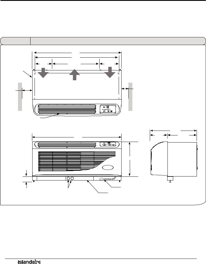
DIMENSIONAL DRAWINGS
Units must be installed in accordance with all applicable codes. Ensure that there is adequate clearance for servicing and proper operation. A minimum of 18 inches in front of the chassis is required. Provide additional space for service technician to work on the unit. Ensure that drapes, beds, bedspreads, furniture, etc., DO NOT block either return or discharge air openings.
Figure 1 |
Dimensional Drawings |
|
42” |
TOP VIEW |
|
|
40” |
|
|
6 1/8” |
24 5/16” |
9 9/16” |
|
WALL SLEEVE |
|
|
|
AIR FLOW |
AIR FLOW |
AIR FLOW |
|
|
|
|
|
0” min |
|
0” min |
|
1” recom- |
|
1” recommended |
|
mended |
|
|
|
FRONT DISCHARGE |
|
|
|
GRILLE |
|
|
|
|
|
|
21 5/8” |
|
42” |
7 7/8” |
13 3/4” |
|
|
|
|
|
|
16” |
|
3” MIN. |
|
|
|
ELECTRICAL KNOCKOUTS |
CORDSET |
|
|
SUBBASE |
|
||
|
FRONT VIEW |
|
|
|
|
SIDE VIEW |
|
ManufacturerofQualityAirConditioningandHeatingProducts•www.islandaire.com•sales@islandaire.com•(800)-886-2759
14
OPTIONS AND ACCESSORIES
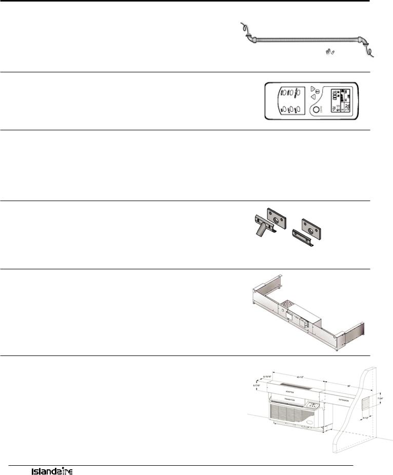
HARD WIRE KIT
Part Number 6040756
•Used in place of a plug-in power cord
•All 265V units require either a hard wire kit or electric subbase
See page 31 for electrical information
REMOTE CONTROL
Part Number 6040694
•Ability to control PTAC from anywhere in the room
•Large full function display
•Operates on two AA batteries
OPTIONAL 2 STAGE HEATER
Available on 208/230 Volt Units With Remote Thermostats
•Reduces energy cost during the heating season
•Maximizes year-round comfort
•Available in 3.6 kW and 5.0 kW only
CONDENSATE DRAIN KIT
Part Number 4090661
•Attaches to wall sleeve base pan to control condensate removal
•Can be adapted for left or right side exterior drainage or internal drain connection
See page 20 for drain kit installation instructions
SUBBASE
•Provides secure enclosure for electrical connections
•Provides structural support for units that extend into the room
•Includes leveling legs for support and precise adjustment
See page 26 for subbase installation instructions
LATERAL DUCT KIT ASSEMBLY
•Allows the air from one PTAC unit to be shared by an adjacent room
•The kit mounts to the top of the unit and can be configured for either right or left discharge
ManufacturerofQualityAirConditioningandHeatingProducts•www.islandaire.com•sales@islandaire.com•(800)-886-2759
15
Loading...