

ISA T1000 PLUS User Manual

DATE: 29/11/2011 DOC.SIE91093 REV.7
SINGLE PHASE RELAY AND
MINIATURE CIRCUIT BREAKERS
TEST SET
MOD. T1000 PLUS
Shop for Power Metering products online at:
1.877.766.5412
www.Power MeterStore.ca

DOC. SIE91093 Rev. 7 Page 3 of 37
APPLICABLE STANDARDS ......................................................................................................................................... 4
1 INTRODUCTION ....................................................................................................................................................... 5
2 CHARACTERISTICS ................................................................................................................................................ 8
2.1 MAIN GENERATOR .................................................................................................................................................... 8
2.1.1 Main AC current ............................................................................................................................................... 8
2.1.2 Main AC voltage ............................................................................................................................................... 9
2.1.3 Main DC voltage ............................................................................................................................................... 9
2.1.4 Other features of main outputs ....................................................................................................................... 10
2.2 AUXILIARY AC VOLTAGE ....................................................................................................................................... 10
2.3 AUXILIARY DC VOLTAGE .................................................................................................................................... 13
2.4 TIMER ..................................................................................................................................................................... 14
2.5 TEST CONTROL ........................................................................................................................................................ 15
2.6 AUXILIARY CONTACTS ............................................................................................................................................. 16
2.7 OUTPUTS MEASUREMENT ........................................................................................................................................ 17
2.7.1 Current and voltage ........................................................................................................................................ 17
2.7.2 Phase angle ..................................................................................................................................................... 18
2.7.3 Other measurements ....................................................................................................................................... 18
2.8 EXTERNAL INPUTS MEASUREMENT ......................................................................................................................... 19
2.8.1 Current measurement ..................................................................................................................................... 19
2.8.2 Voltage measurement ...................................................................................................................................... 20
2.8.3 Other measurements ....................................................................................................................................... 20
2.9 DISPLAY .................................................................................................................................................................. 21
2.10 MENU SELECTIONS ................................................................................................................................................ 21
2.11 OTHER CHARACTERISTICS ..................................................................................................................................... 27
2.12 OPTIONS ................................................................................................................................................................ 29
2.12.1 Power supply, code PII81093 ....................................................................................................................... 29
2.12.2 Connection cable kit, code ZII18093 ............................................................................................................ 29
2.12.3 Transit case, code PII17093 ......................................................................................................................... 29
2.12.4 “E” model: higher AC voltage outputs, code PII92093 ............................................................................... 30
2.12.5 D1000 differential relay test module, code PII40093 .................................................................................. 30
2.12.6 TD1000 PLUS model: auxiliary AC current output, code PII94093 .......................................................... 30
2.12.7 TD1000 PLUS 15Hz model: higher power at low frequency, code PII93093............................................. 31
2.12.8 FT/1000 current filter, code PII16093 ......................................................................................................... 32
2.12.9 SHA-1000 scanning head for T1000 PLUS and T3000, code PII43102 ..................................................... 32
2.12.10 Outputs transducer and connection cables for low level signal relays..................................................... 33
3 PROTECTIONS ........................................................................................................................................................ 35
APPENDIX 1: AUXILIARY AC OUTPUT FEATURES COMPARISON .............................................................. 36
APPENDIX 2: MENU SELECTIONS FLUX DIAGRAM ......................................................................................... 37
Shop for Power Metering products online at:
1.877.766.5412
www.Power MeterStore.ca

DOC. SIE91093 Rev. 7 Page 4 of 37
APPLICABLE STANDARDS
The test set conforms to the EEC directives regarding Electromagnetic Compatibility and Low
Voltage instruments.
A) Electromagnetic Compatibility:
Directive no. 2004/108/EC. Applicable Standard : EN61326-1 + A1 + A2.
EMISSION
- EN 61000-3-2: Harmonic content of power supply. Acceptable limits: basic.
- EN 61000-3-3: Limitation of voltage fluctuations and flicker. Acceptable limits: basic.
- CISPR16 (EN 55011 class A): Limits and measurement methods of radio-electric disturbances for
industrial, medical and scientific instruments at radio-electric frequencies.
Acceptable limits for conducted emission:
. 0.15-0.5 MHz: 79 dB pk; 66 dB avg.
. 0.5-5 MHz: 73 dB pk; 60 dB avg.
. 5-30 MHz: 73 dB pk; 60 dB avg.
Acceptable limits for radiated emission:
. 30-230 MHz: 40 dB (30 m)
. 230-1000 MHz: 47 dB (30 m)
IMMUNITY
- EN 61000-4-2: Immunity tests for ESD. Test values: 8 kV in air; 4 kV in contact.
- EN 61000-4-3; Immunity tests for radio frequency interference. Test values (f= 900 5 MHz):
field 10 V/m, modulated AM 80%; 1 kHz
- EN 61000-4-4; Immunity tests for high speed transients (burst). Test values: 2 kV peak; 5/50 ns.
- EN 61000-4-5; Immunity tests for surge. Test values: 1 kV peak differential mode; 2 kV peak
common mode; 1.2/50 us.
- EN 61000-4-6: immunity to low-voltage sinusoidal waveform. Test values: 0.15-80 MHz, 10
Vrms, 80% AM 1 kHz.
- EN 61000-4-8: Immunity tests for low frequency magnetic fields. Test values: 30 Arms/m.
- EN 61000-4-11: Immunity test for power supply drops. Test value: 1 cycle; 100% drop.
B) Low Voltage Directive:
- - Directive n. 2006/95/EC.
- Applicable standard: EN 61010-1. In particular, for a pollution degree 2: dielectric rigidity 1.4 kV
AC, 1 minute.
- Inputs/outputs protection: IP 2X - EN60529.
- Operating temperature: 0 to 50 °C; storage: -20 °C to 70 °C.
- Relative humidity: 5 - 95%, without condensing.
- Vibration: IEC 68-2-6 (20 m/s^2 at 10 – 150 Hz);
- Shock: IEC 68-2-27 (15 g; 11 ms; half-sine).
- Altitude: less than 2000 m.
Shop for Power Metering products online at:
1.877.766.5412
www.Power MeterStore.ca

DOC. SIE91093 Rev. 7 Page 5 of 37
1 INTRO DUCTI ON
The relay test set mod. T1000 PLUS is suited for the testing and adjustments of Low Voltage
Miniature Circuit Breakers and of the following types of relays.
:
Distance protection (phase by phase) (21, *)
Synchrocheck (25)
Thermal (26)
Undervoltage and overvoltage (27, 59)
Directional power (32)
Undercurrent (37)
Negative sequence overcurrent (46)
Phase sequence voltage relay (47)
Incomplete sequence relay (48)
Definite time overcurrent (50- 50N)
Time dependent overcurrent (51 - 51N)
Power factor (55)
Directional overcurrent (67)
Directional earth fault (67N)
Automatic reclosing devices (79)
Frequency (81<, 81>)
Load shed (frequency ROC, 81R)
Motor overload protection (86)
Differential (87)
Directional voltage (91)
Tripping relays (94)
In addition to the above, T1000 PLUS can test:
. Converters: V; I; φ°; p.f.; W; VAr; f., both 0 to 5 and 4 to 20 mA.
. Energy meters, single phase or three phase.
T1000 PLUS is also suited to perform the following tests:
Finding the CT saturation knee;
Current and voltage transformer ratio test;
Burden measurement of the protective relay test equipment;
Impedance measurement;
Polarity (direction) tests;
Timed fault injection;
Off delay - possi bility to time delay the turning-off of generation after
tripping.
In addition, T1000 Plus features:
o Reduced power operation, for the fine current regulation;
o Fine voltage regulation;
o Display the values of: current, AC voltage, DC voltage, time, and of derived
measurements.
o Freeze function (HOLD) for voltage and current readings.
o The timer has separated inputs for start and stop impulses.
o The timer start and stop inputs respond to changes (EDGE).
o Start and stop input levels are displayed by LED’s.
Shop for Power Metering products online at:
1.877.766.5412
www.Power MeterStore.ca

DOC. SIE91093 Rev. 7 Page 6 of 37
o The relay intervention is displayed by an LED.
o Test modes: ON, ON+TIME, OFF+TIME.
o The device is provided with USB and serial port for the communication to the
computer (notebook).
o The TDMS Windows compatible software allows setting, testing and storing (also in
a built-in Data Base) all data. Printing plus exporting report results in Words, Excel,
PDF formats.
o TDMS is upgraded for free in the ISA WEB site.
o Main output adjustments: 0-250 A AC, 0-250 V AC (T1000E: 0-500 V AC), 0-300
V DC.
o Auxiliary AC voltage source, range 0-260 V AC (T1000E: 0-500 V AC), 0-359°
phase shift, 15 to 550 Hz, separated from the other outputs with independent
settings. Optional TD1000PLUS model: also an output of 0-20 A AC, phase and
frequency adjustable.
o Auxiliary DC voltage source; range 20-240 V DC. Equipped with overload
protection, and separated from the other outputs.
o Auxiliary AC and DC voltage sources can be turned ON and OFF via
pushbuttons.
o Two auxiliary relay contacts, that can be independently timed with respect to test
start and stop.
The instrument contains three separate generators:
. Main generator: it generates either AC current, AC voltage; DC voltage;
. Auxiliary AC voltage generator: it generates an independent, phase adjustable AC voltage;
. Auxiliary DC voltage generator: it generates the DC voltage that feeds the relay under test.
All outputs are adjustable and metered at the meantime on the large, graphic LCD display. With the
multi-purpose knob and the LCD display it is possible to enter the MENU mode, which allows
setting many functions, which make T1000 PLUS a very powerful testing device, with manual and
semi-automatic testing capabilities, and with the possibility to transfer test results to a PC via the
RS232 interface. These results can be recorded, displayed and analysed by the powerful TDMS
software, which operates with all WINDOWS versions, starting from WINDOWS 98 included.
The basic T1000 PLUS function is to generate current and voltages and to stop generation as the
relay trips. Test results are kept in memory, and can be transferred to a PC at a later time, along
with settings.
The ease of operation has been the first goal of T1000 PLUS: this is why the LCD is graphic, and so
large. With it, the dialogue in MENU mode is made easy. Besides, all T1000 PLUS outputs are
continuously measured, and output values are displayed, with no extra effort to the operator. Also
the show waveform feature can be of help: any doubt about strange measurements, distortion and so
on can be solved.
This is also why we have added the reduced power feature. Modern relays have a very low burden.
As current output is a low impedance voltage generator, adjusting low currents and/or current on
low burdens is quite difficult because one has to operate at the very beginning of the adjustment
knob. In this situation it is possible to connect resistors in series; however, one must be careful not
to exceed the maximum current rating, and the wiring is more complicated. The solution to this
problem is just to reduce the available power: this is easily performed via the multi-function knob.
With less power, the maximum voltage is reduced by a factor of five; the adjustment span on the
knob is increased accordingly.
Shop for Power Metering products online at:
1.877.766.5412
www.Power MeterStore.ca
DOC. SIE91093 Rev. 7 Page 7 of 37
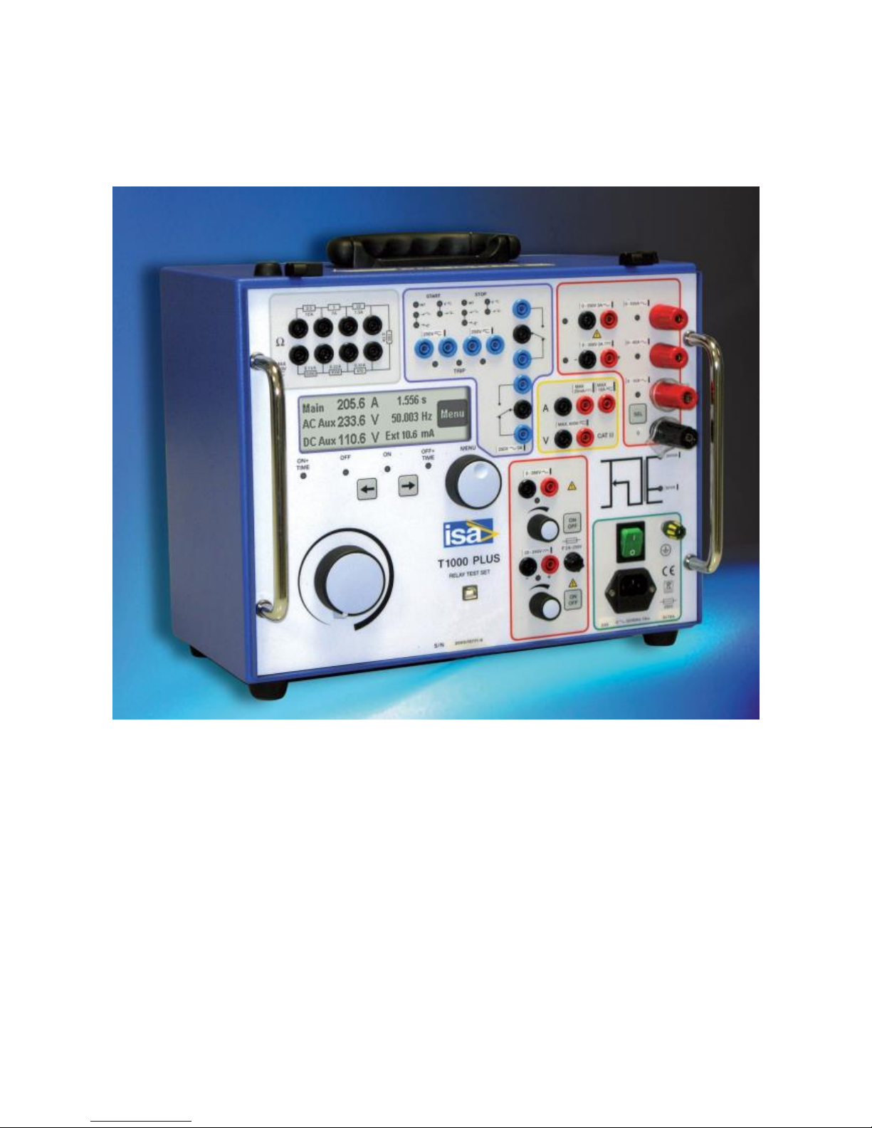
The instrument is housed in a transportable aluminium box, which is provided with removable
cover and handles for ease of transportation.
The test set is shown here below.
NOTE: WINDOWS is a trademark of MICROSOFT Inc.
Shop for Power Metering products online at:
1.877.766.5412
www.Power MeterStore.ca

DOC. SIE91093 Rev. 7 Page 8 of 37
2 CHARA CTERISTICS
2.1 MAIN GENERATOR
The main generator has three outputs: currents, voltage AC, voltage DC. The following
specification applies to the separate usage of these outputs. It is possible to use them at the
meantime, provided that the total maximum load is not exceeded.
The main generator is made of a variable transformer followed by a transformer. The variable
transformer does not reach the zero position; so, when you are adjusting the output current on a low
burden, the minimum current can be up to 5% of the range. If this is a problem, select the 60 VA
power: the current is reduced to one fifth.
For all main output generators there is no specification related to the output distortion. This is
because the output waveform follows the mains supply waveform, with its distortion. If it is desired
to avoid distortions, the option FT100 solves the problem.
2.1.1 Main AC current
- Type of generator: voltage, high current output: the current depends upon the burden.
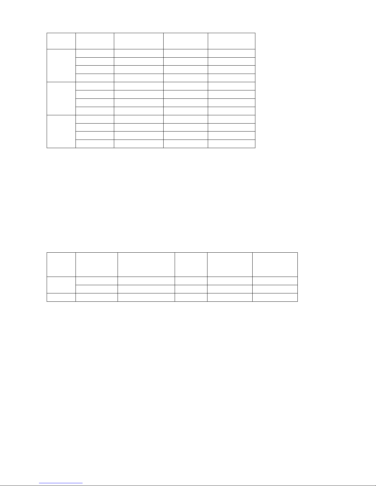
- On all outputs is provided the capability of generating the selected current at maximum power or
at reduced power. Reduced power selection eases the current adjustment for modern relays, where
the load is negligible. Current ranges; available power; duty cycle: see the table below.
1) MAXIMUM POWER 300 VA
RANGE
A AC
CURRENT
OUTPUT
A
MAXIMUM
POWER
VA
LOAD
TIME
s
RECOVERY
TIME
min
100
30
300
STEADY
-
50 30 min
100
75 600
45
100
800
60
15
150 3
10
250
1000 1 5
40
12
300
STEADY
-
20 30 min
100
30 600
45
40
800
60
15
60 3
10
80
1000 1 5
10
5
400
STEADY
-
7.5
15 min
45
10
800
60
15
15 5
10
20
1000 2 5
2) MAXIMUM POWER 60 VA
RANGE
CURRENT
MAXIMUM
LOAD
RECOVERY
Shop for Power Metering products online at:
1.877.766.5412
www.Power MeterStore.ca
DOC. SIE91093 Rev. 7 Page 9 of 37
A AC
OUTPUT
A
POWER
VA
TIME
s
TIME
min
100
30
60
STEADY
-
38 10 min
45
53 60
10
70 0.75
2
40
12
60
STEADY
-
17 10 min
45
23 60
10
36 1
2
10
5
60
STEADY
- 6
10 min
45 7
60 2 10 1,5
2
- Power selection: via menu.
- Connection: four high power sockets, with safety protections, marked: 0; 10 A; 40 A; 100 A.
2.1.2 Main AC voltage
- The main AC voltage is isolated from the main AC current.
- AC voltage range: 250 V or 54 V (reduced power; power supply 230 V), or 108 V (reduced
power; power supply 110 V).
- Available power and duty cycle: see table below.
RANGE
V AC
VOLTAGE
OUTPUT
V
LOAD
CONSUMPTION
VA
LOAD
TIME
min
RECOVERY
TIME
min
REDUCED
POWER
250
250
500
STEADY
-
NO
250
750
10
45
NO
54 (108)
54 (108)
60
STEADY
-
YES
- Connection: two safety banana sockets.
2.1.3 Main DC voltage
- The main DC voltage is isolated from the main AC current, but not from the main AC voltage
- DC voltage range: 300 V or 60 V (reduced power; power supply 230 V), or 120 V (reduced
power; power supply 110 V).
- Available power and duty cycle: see table below.
Shop for Power Metering products online at:
1.877.766.5412
www.Power MeterStore.ca
DOC. SIE91093 Rev. 7 Page 10 of 37
RANGE
V DC
VOLTAGE
OUTPUT
V
LOAD
CONSUMPTION
W
LOAD
TIME
min
RECOVERY
TIME
min
REDUCED
POWER
300
300
300
STEADY
-
NO
300
500
10
45
NO
60 (120)
60 (120)
60
STEADY
-
YES
- Type of DC voltage: unregulated, via diode bridge rectifier and capacitor.
- Connection: two safety banana sockets.
2.1.4 Other features of main outputs
- Zero crossing control. Main AC outputs are generated and stopped as the output waveform crosses
zero. This implies that in mode ON+TIME the output drops to zero from 0 to one cycle after STOP
is detected.
- Overload alarm message. When the nominal current range is trespassed a message is displayed.
- Thermal protection: by NTC. Trespassing of the maximum temperature is signalled by a message.
- Output adjustment: from less than 5% to 100% of the output.
- Output measurement. The used output (current, V AC, V DC) is selected by a dedicated pushbutton; the selected socket is confirmed by a light.
2.2 AUXILIARY AC VOLTAGE
- The auxiliary AC voltage output, V AC aux, is isolated from the main AC current and voltage.
- Output ranges: 65 – 130 - 260 V. NOTE: at 15 Hz, the output ranges are: 25, 50, 100 V.
- Range selection: software driven, by the multi-function knob and LCD display.
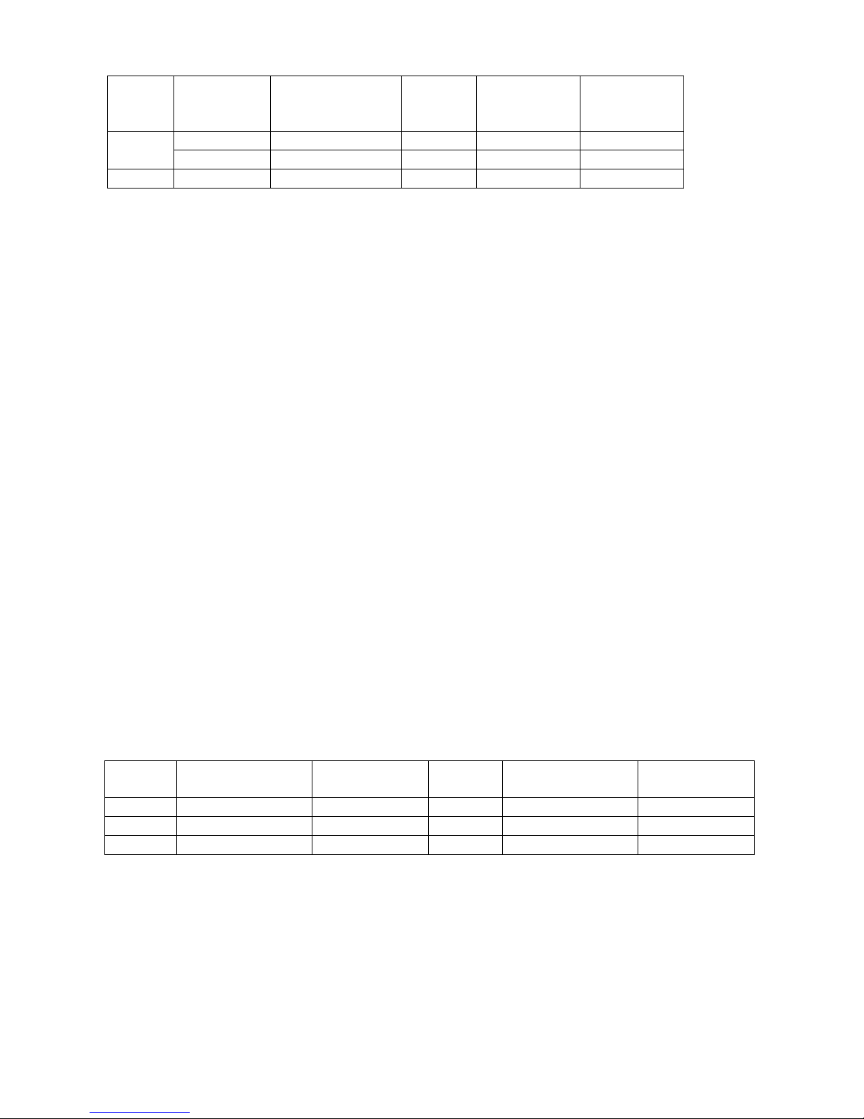
- Auxiliary voltage power: 30 VA, continuous duty, at full range; 40 VA for 1 minute. At 15 Hz, the
power is: 8.5 VA at 25 V; 13 VA at 50 V; 16 VA at 100 V. For lower voltages the limiting current
is the following.
RANGE
V
MAX CURRENT
mA; > 40 Hz
MAX POWER
VA; > 40 Hz
RANGE
V; 15 Hz
MAX CURRENT
mA; 15 Hz
MAX POWER
VA; 15 Hz
65
500
30 (40)
25
350
8.5
130
250
30 (40)
50
260
13
260
125
30 (40)
100
160
16
- Output stability: the adjusted voltage drops of 5% maximum from zero load to full load.
- Output adjustment: continuous. For normal tests the voltage is continuously supplied, and the
output voltage is adjusted by the dedicated knob.
- Output connection: safety banana sockets.
- ON-OFF switch to enable the output. A light confirms when the output is available.
Shop for Power Metering products online at:
1.877.766.5412
www.Power MeterStore.ca
DOC. SIE91093 Rev. 7 Page 11 of 37
- Possibility to phase shift the auxiliary AC voltage output with respect to: the main current and the
main AC voltage. The phase angle reference is the auxiliary voltage. Phase shifter characteristics:
. Phase angle adjustment: via the multi-function knob.
. Phase angle range: from 0° to 360°.
. Adjustment resolution: 1° (degree).
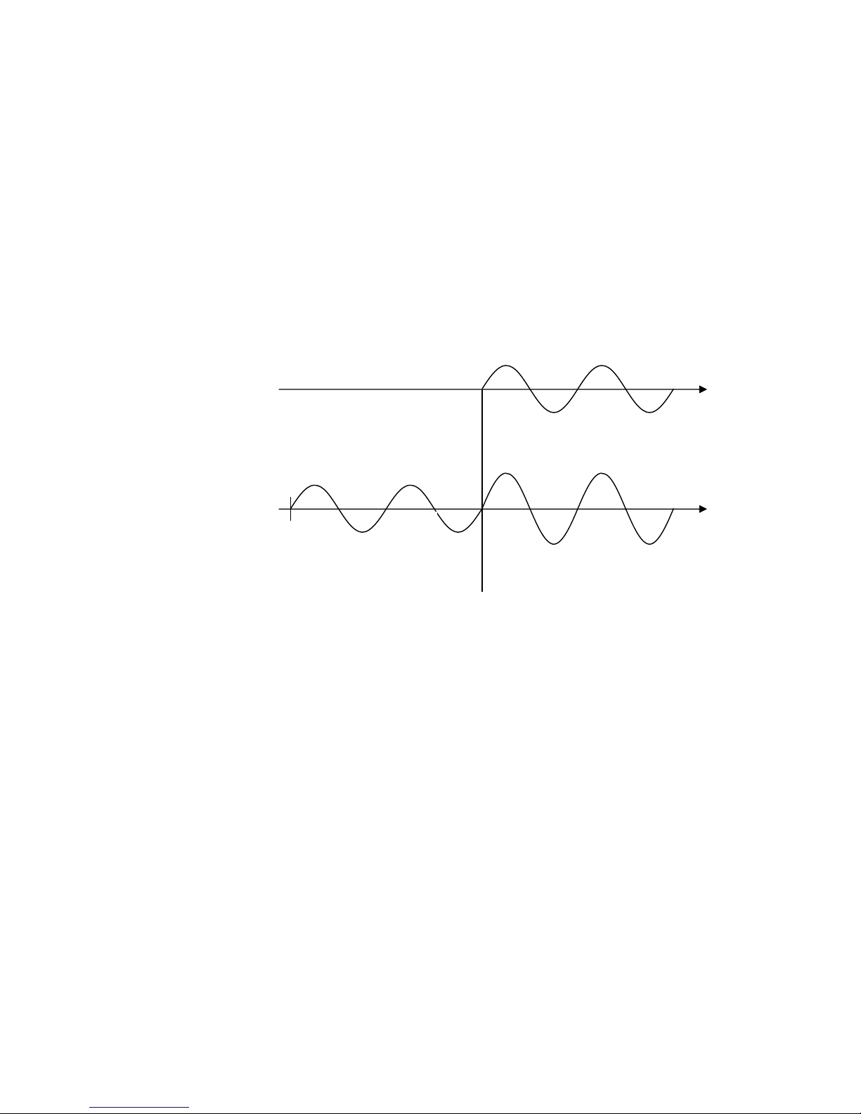
- Possibility to define the pre-fault voltage: in this mode, the control knob allows to adjust the prefault value, while the dedicated knob adjusts the fault value. Voltage output selection is automatic:
pre-fault voltage with test stopped; fault voltage with test started. The switch from a value to the
other one is performed without falling to zero. The main current or voltage is generated at the zero
crossing; the fault one is generated at the meantime of main voltage or current (figure 1). The
selection of the reference is performed automatically, following the selection of main output
measurement. If the main DC voltage is selected the reference is taken on the main AC voltage.
This feature allows testing voltage relays (27-59) or synchronizing relays (25).
MAIN AC CURRENT
(MAIN AC VOLTAGE)
AUXILIARY
VOLTAGE
TEST START
Figure 1 - Output voltage control
- Possibility to phase shift the pre-fault voltage, at an angle independent from the fault voltage. This
parameter serves during the test of distance relays, when phase to phase faults are simulated: as test
starts, the fault voltage changes amplitude and phase with respect to the pre-fault value (figure 2)
Shop for Power Metering products online at:
1.877.766.5412
www.Power MeterStore.ca

DOC. SIE91093 Rev. 7 Page 12 of 37
V1 PRE-FAULT
V1 FAULT
FAULT ANGLE
V1 FAULT
PRE-FAULT ANGLE
I1 FAULT
V2 V3
Figure 2 – Prefault voltage
- Possibility to define the duration TPF of pre-fault generation, after test start, prior to generating
fault values. This feature is necessary to test synchronization relays: the main output voltage can be
applied prior to frequency switching. TPF range: from 0 to 999.99 s.
- Possibility to change the frequency of the auxiliary AC voltage output. Frequency generation
characteristics:
. Frequency range: 15.000 Hz to 550.000 Hz.
. Frequency adjustment: 1 mHz, via control knob.
. Frequency generation error: 100 ppM.
. It is possible to switch from the nominal frequency to the fault one. The nominal frequency is also
selectable, independently from the fault.
. Switching from nominal frequency to fault frequency is performed without altering the output
voltage (figure 3).
TEST
OFF
ON + TIME
V1 AMPLITUDE
VN
V2 AMPLITUDE
VN
V2 FREQUENCY
FN
FTEST
PRE-FAULT TIMING
T PF
TIMING MEASUREMENT
FN
Shop for Power Metering products online at:
1.877.766.5412
www.Power MeterStore.ca
 Loading...