

ISA T1000 Introductory Manual
Istrumentazioni Sistemi Automatici S.r.l.
VIA BERGAMO 41 - 21020 TAINO (VA) - ITALY
OFFICES TEL. +39.0331.956081 - FAX +39.0331.957091
LAB: TEL. +39.0331.956483 -
E-MAIL isa@isatest.com
WEB www.isatest.com
DATE: 25/04/2006 DOC.MIE12093 REV. 1
T1000
INTRODUCTORY GUIDE

DOC. MIE12093 Rev. 1 Page 2 of 52
REVISIONS SUMMARY VISA
N PAGE DATE
1 All 25/04/2006 Preliminary issue Lodi.

DOC. MIE12093 Rev. 1 Page 3 of 52
SHORT FOREWORD .......................................................................................................................................................4
INTRODUCTION.............................................................................................................................................................5
1 TEST SET EXPLANATION ........................................................................................................................................7
1.1 CONNECTION TO THE RELAY AND POWER-ON.............................................................................................................7
1.2 TEST CONTROL...........................................................................................................................................................7
1.3 CURRENT GENERATION............................................................................................................................................ 10
1.4 AC VOLTAGE GENERATION FROM MAIN OUTPUT ......................................................................................................11
1.5 DC VOLTAGE GENERATION FROM MAIN OUTPUT......................................................................................................12
1.6 AC VOLTAGE GENERATION FROM THE AUXILIARY OUTPUT ...................................................................................... 12
1.7 DC VOLTAGE GENERATION FROM THE AUXILIARY OUTPUT ......................................................................................14
1.8 AUXILIARY CONTACT............................................................................................................................................... 15
1.9 THE TIMER...............................................................................................................................................................15
1.10 FINDING RELAY THRESHOLDS.................................................................................................................................16
1.10.1. Introduction.................................................................................................................................................16
1.10.2. First threshold trip and drop-off..................................................................................................................17
1.10.3. Second threshold trip and drop-off .............................................................................................................18
1.11 FINDING RELAY TIMINGS ........................................................................................................................................18
1.12 BASIC TEST PRINCIPLES.......................................................................................................................................... 20
1.12.1. Introduction..................................................................................................................................................20
1.12.2. Parameter vs. time characteristic ................................................................................................................20
1.12.3. Parameter vs. parameter characteristic....................................................................................................... 21
1.13 USE OF THE TEST SET AS A MULTIMETER................................................................................................................23
2 TEST SET AND POP-UP MENU ..............................................................................................................................25
2.1 THE FRONT PANEL....................................................................................................................................................25
2.2 DISPLAY AND CONTROL LIGHTS................................................................................................................................27
2.3 THE POP-UP MENU....................................................................................................................................................27
3 THE HELL, IT DOESN’T WORK............................................................................................................................34
3.1 INTRODUCTION ........................................................................................................................................................ 34
3.2 ERROR MESSAGES....................................................................................................................................................35
3.3 TROUBLE SHOOTING ................................................................................................................................................36
3.4 PHYSICAL DESCRIPTION ...........................................................................................................................................37
4.4.1 Protection fuses...............................................................................................................................................39
4.4.2 Auxiliary supplies............................................................................................................................................39
4.4.3 No power at power-on.....................................................................................................................................40
3.5 AUXILIARY DC VOLTAGE FAULT ................................................................................................................... 40
3.6 NO OUTPUT FROM THE MAIN CURRENT AND VOLTAGE .............................................................................................41
3.7 DOES NOT MEASURE THE MAIN CURRENT ................................................................................................................41
3.8 THE DISPLAY BACKLIGHT DOES NOT TURN ON.......................................................................................................... 42
3.9 THE AC VOLTAGE MEASUREMENT IS NOT STABLE ................................................................................................... 43
3.10 THE TRIP INPUT IS NOT DETECTED OR TIMING ERROR .............................................................................................43
3.11 PROBLEMS DURING UPGRADE ................................................................................................................................43
3.12 THE ENCODER IS BROKEN ......................................................................................................................................44
3.13 THE FAULT CANNOT BE FIXED................................................................................................................................ 44
3.14 CALIBRATION......................................................................................................................................................... 46
3.14.1 Introduction..................................................................................................................................................46
3.14.2 Calibration procedure.................................................................................................................................. 46
3.14.3 T/1000 output calibration............................................................................................................................47
3.14.4 T/1000 external measurements calibration................................................................................................. 49
APPENDIX 1 SPARE PARTS LIST.............................................................................................................................50

DOC. MIE12093 Rev. 1 Page 4 of 52
SHORT FOREWORD
Dear T/1000 user,
I often wondered why the user’s manual is not very much used, even if it includes valuable
information. As me too I am a user of such manuals, the answer I have given myself is that valuable
information are concealed somewhere in the thick thing, and I do not have time to waste to find it.
So, either the manual is actually of help, or I ignore it.
This is why I decided to split the T/1000 manual in three: specification, with all performance
details; application manual, with instructions about how to use it one its operation is understood;
introductory guide, with the device description and basic information. The idea is that you may read
once the introductory guide or the specification, while you need to follow application examples
more than once; so, why not to split the manual in three?
Have a good work with T/1000!
Primo Lodi
Q&A Manager

DOC. MIE12093 Rev. 1 Page 5 of 52
INTRODUCTION
The single phase relay test set mod. T/1000 is suited for the testing and adjustments of the following
types of relays; the table lists also the paragraph that explains the test procedure.
Type of relay IEEE code PARAGRAPH
- Distance* 21 1.12
- Synchronizing 25 1.8
- Over/under-voltage 27 - 59 1.2
- Power, varmetric or wattmetric 32 - 92 1.4
- Under current 37 1.1
- Loss of field 40 1.10
- Reverse phase current 46 1.4
- Instantaneous overcurrent 50 1.1
- Ground fault 50N 1.1
- Timed overcurrent 51 1.1
- Power factor 55 1.4
- Directional overcurrent 67 1.5
- Directional ground fault 67N 1.5
- Automatic reclose 79 1.11
- DC voltage 80 1.3
- Frequency 81 1.6
- Frequency rate of change 81 1.7
- Motor protection 86 1.1
- Differential ** 87 1.1
- Directional voltage 91 1.5
- Tripping relay 94 1.9
- Voltage regulation 1.2
- Thermal 1.1
- Timers 1.9
* For distance relays three T/1000 are necessary.
** Differential starter circuit
In addition to the above, T/1000 can test:
. Converters: V; I; f°; p.f.; W; VAr; f., both 0 to 5 and 4 to 20 mA.
. Energy meters, single phase or three phase.
The instrument contains three separate generators:
. Main generator, which generates either AC current, AC voltage; DC voltage;
. Auxiliary a.c voltage generator, that generates an independent, phase shifting a.c voltage;
. Auxiliary DC voltage generator, that generates the DC voltage that feeds the relay under test.
All outputs are adjustable and metered at the meantime on the large, graphic LCD display. With the
multi-purpose knob and the LCD display it is possible to enter the MENU mode that allows setting
many functions, which make T/1000 a very powerful testing device, with manual and semiautomatic testing capabilities, and with the possibility to transfer test results to a PC via the RS232
interface. These results can be recorded, displayed and analyzed by the powerful TDMS software,

DOC. MIE12093 Rev. 1 Page 6 of 52
which operates with all WINDOWS versions, and allows creating a data base of all tests in the
plant.
The basic T/1000 function is to generate current and voltages and to stop generation as the relay
trips. Test results are kept in memory, and can be transferred to a PC at a later time, along with
settings.
The ease of operation has been the first goal of T/1000: this is why the LCD is graphic, and so large.
With it, the dialogue in MENU mode is made easy. Besides, all T/1000 outputs are continuously
measured, and output values are displayed, with no extra effort to the operator. Also the show
waveform feature can be of help: any doubt about strange measurements, distortion and so on can
be solved.
This is also why we have added the reduced power feature. Modern relays have a very low burden.
As current output is a low impedance voltage generator, adjusting low currents and/or current on
low burdens is quite difficult because one has to operate at the very beginning of the adjustment
knob. In this situation it is possible to connect resistors in series; however, one must be careful not
to exceed the maximum current rating, and the wiring is more complicated. The solution to this
problem is just to reduce the available power: this is easily performed via the multi-function knob.
With less power, the maximum voltage is reduced by a factor of 4.4; the adjustment span on the
knob is increased accordingly.
Additional features are:
. Two meters, current and voltage, with independent inputs, allow measuring T/1000 outputs or any
other source;
. An auxiliary contact, that follows START and STOP inputs, allows simulating the circuit breaker;
. A set of resistors allows easing output adjustment.
The instrument is housed in a transportable aluminum box, that is provided with removable cover
and handles for ease of transportation.
NOTE: WINDOWS is a trademark of MICROSOFT inc.

DOC. MIE12093 Rev. 1 Page 7 of 52
1 TEST SET EXPLANATION
1.1 CONNECTION TO THE RELAY AND POWER-ON
At first, be sure that the main control knob (6)is turned (rotated) to the zero position (complete
counter-clockwise). The reason is that the current generator is actually a high current voltage
generator. If the output is connected to the load (typically low impedance), as soon as the test is
started, a very high current can circulate in the circuit.
Next connect the mains supply cable to the instrument and then to the supply. THE SUPPLY
VOLTAGE MUST BE THE SAME AS INDICATED ON THE PLATE.
Power-on T-1000: a diagnostic sequence controls:
. Key microprocessor board components;
. Auxiliary supply voltages.
If something is wrong, the operator is alerted by a message.
At the end of it, default selections are active; T-1000 is in the OFF state.
Perform the first selections, according to the type of relay to be tested:
. Main output socket, acting on the selector push-button (57).
. Auxiliary AC voltage: range; type of generation; value.
. Auxiliary DC voltage: range; value.
. Start and Stop timer inputs.
Connect the relay to be tested to the output sockets that have the indication light (LED) on.
The following is the list of protections that avoid damaging T-1000 in case of errors.
. Fuse on the mains supply.
. Thermal NTC sensor on the main and auxiliary transformers. In case of over-temperature, an alarm
message is displayed.
. Thermal sensors on the SCR that controls current injection, and of the internal temperature. In case
of over-temperature, an alarm message is displayed.
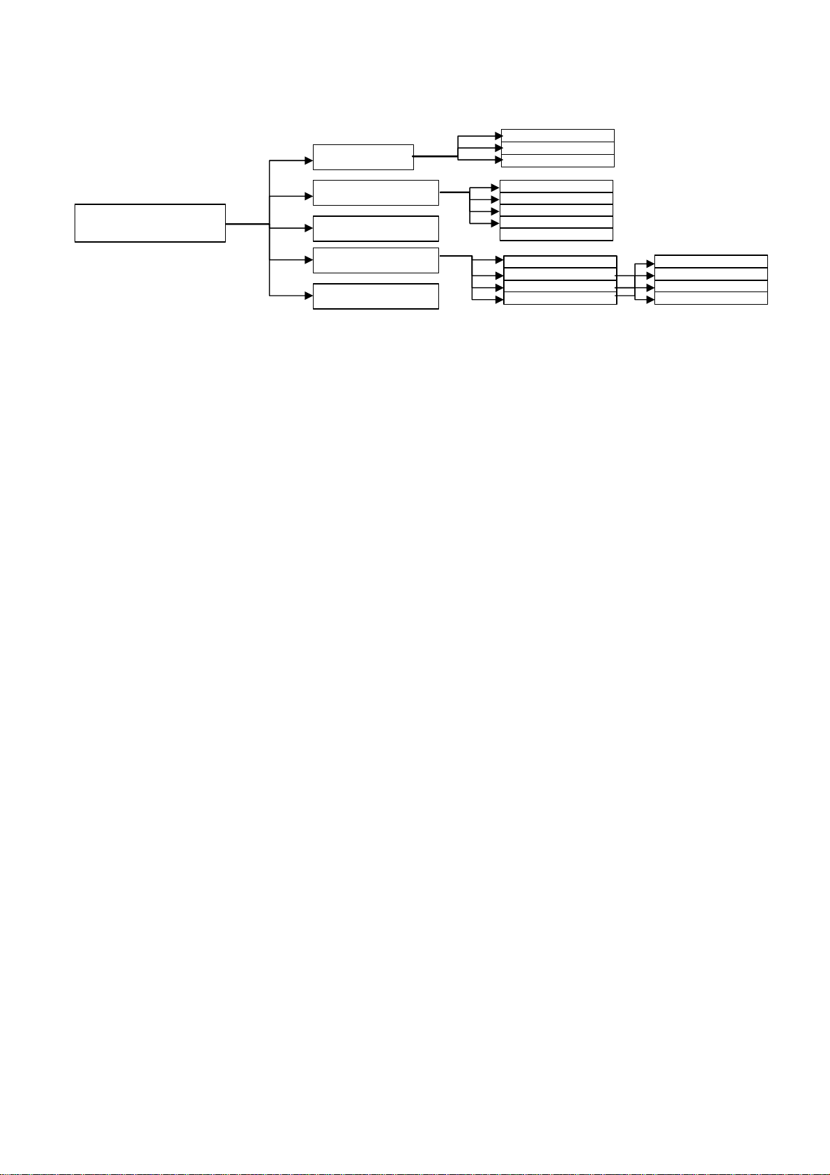
1.2 TEST CONTROL
The T-1000 front panel is explained in next paragraph.
T-1000 generation is controlled by the two keys < (55) and > (56).
Settings and menu selections are controlled by the multi-function knob with switch (22): see next
paragraph for menu selections description. At power-on T-1000 generation is OFF, as confirmed by
LED (50). The ON selection serves for finding relay thresholds; selections ON+TIME and
OFF+TIME serve to measure relay timing.
DOC. MIE12093 Rev. 1 Page 8 of 52
Normal (default)
Trip + pulse time
Reclose mode
Maintained
Momentary
Timed
External
OFF delay
1
period
8 periods
Save min
Save max
Don’t save
Automatic at trip
Confirm at trip
Manual
The following flow diagram summarises all available test control selections.
Test mode
Fault injection
TEST CONTROL
Test power
Save
Auxiliary contact
The performance of T-1000 in Normal Test mode is the following.
. OFF: main outputs are not generated; Vac aux is generated, and it can be either the pre-fault value
or the fault value, according to selections; Vdc aux is generated. In this condition, any trip of Stop
input is ignored.
. ON: timer starts; main outputs are generated; Vac aux has the fault value; Vdc aux does not
change. In this situation any trip at Stop input is detected; it is possible to verify and memorize the
relay threshold, both trip and reset. As the relay trips, the TRIP LED (43) turns on for 5 seconds;
during 5 seconds, parameters at trip are displayed; then, the standard measurement is restored. Test
results can be saved according to Save selections.
. From OFF to ON + TIME: main outputs are generated and the timer starts according to selections;
as Stop trips or resets, T-1000 returns to OFF, the TRIP LED (43) turns on and parameters at trip
are displayed until ON or ON+TIME are selected. Test results can be saved according to Save
selections.
. From ON to OFF + TIME: main outputs are removed the timer starts according to selections; as
STOP is sensed, T-1000 returns OFF, the TRIP LED (43) turns on and parameters at trip are
displayed until ON or ON+TIME are selected. Test results can be saved according to Save
selections.
Other test mode selections:
. Trip + pulse time: the timer measures the delay and the duration of the trip impulse.
. Reclose test. It is possible to select via menu the test of a reclosing scheme. In this operating mode
T-1000 automatically applies current as soon as the RECLOSE command is sensed at START
input. The test set measures and stores the trip delay and the delay between trip falling edge and
RECLOSE trailing edge (see figure 4). Maximum number of Reclose commands: 49; maximum test
commands for all Reclose commands: 9999 s.

DOC. MIE12093 Rev. 1 Page 9 of 52
FAULT 1 2
TRIP (STOP) 1 2
RECLOSE (START) 1 2
TIME MEASUREMENTS D1 R1 D2 R2
Other Fault injection selections:
. Maintained (default):
.. ON mode: fault outputs are generated until OFF is selected.
.. ON+TIME or OFF+TIME: as the STOP input is sensed, T-1000 returns OFF.
. Momentary: in ON mode, main outputs are generated until the > push-button is pressed;
. Timed: in all modes (ON; ON+TIME; OFF+TIME), fault outputs are generated for the
programmed maximum time; after this, T-1000 returns OFF. Any trip after this time is not sensed.
. External. This mode allows for the synchronization of more T-1000: they start generating upon
reception of the START input, that is selected in External mode.
. OFF delay: fault parameters can be maintained for the specified time after relay trips: this allows
simulating the circuit breaker delay.
Test power selection: it allows reducing the available power; this increases the adjustment
sensitivity for low current tests on low burden relays.
Save selections:
. No automatic saving.
. Automatic test data saving as relay trips. A pop-up window confirms the saving and tells the test
number.
. Test data can be saved after confirmation. After relay trip, pressing the multi-function knob the
operator can save the test result.
. Manual test data saving. This selection can be used any time: it serves if the trip is confirmed by a
light and not by a contact.
Test data selections. Data to be saved can be measured the following way:
. One period before the trip: this is the standard selection for timing measurement, and for threshold
test, provided that trip time is not long;
. Eight periods before the trip (less if eight are not available): this is used in case of unstable test
results due to waveform distortion;
. Save the minimum period within 0,5 s before trip: this is used for high threshold measurement,
when the timing is long;
. Save the maximum period within 0,5 s before trip: this is used for low threshold measurement,
when the timing is long.
Auxiliary contact delay: the switch of the auxiliary contact can be timed with respect to test start.

DOC. MIE12093 Rev. 1 Page 10 of 52
1.3 CURRENT GENERATION
If the following current limits and time duration of main current outputs are trespassed, the
generation is interrupted, and the operator is warned by an alarm message.
1) MAXIMUM POWER 300 VA
RANGE
A AC
100
40
10
2) MAXIMUM POWER 60 VA
RANGE
A AC
100
40
10
This generator serves for the test of current, power, directional, distance relays, where current or
current and voltage are necessary. The procedure is the following.
CURRENT
OUTPUT
A
30 300 STEADY 50 30 min 100
75 600 45
100 800 60 15
150 3 10
250 1000 1 5
12 300 STEADY -
20 30 min 100
30 600 45
40 800 60 15
60 3 10
80 1000 1 5
5 400 STEADY -
7.5 15 min 45
10 800 60 15
15 5 10
20 1000 2 5
CURRENT
OUTPUT
A
30 60 STEADY 38 10 min 45
53 60 10
70 0.75 2
12 60 STEADY 17 10 min 45
23 60 10
36 1 2
5 60 STEADY 6 10 min 45
7 60 2
10 1,5 2
MAXIMUM
POWER
VA
MAXIMUM
POWER
VA
LOAD
TIME
s
LOAD
TIME
s
RECOVERY
TIME
min
RECOVERY
TIME
min

DOC. MIE12093 Rev. 1 Page 11 of 52
. At first, be sure that the main control knob (6) is turned (rotated) to the zero position (complete
counter-clockwise).
. Power-on T-1000.
. Select by the push-button (57) the measurement on the desired output sockets (13), according to
the maximum current to be generated: the LED turns on; the AC voltage value is displayed.
. Connect the relay to be tested to sockets (13). Consider that for tests of 40 A up it is necessary to
connect the relay by a wire having at least a cross section of 10 sq. mm; for lower currents, a cross
section of 2.5 sq. mm can be used.
. Press ON and adjust the output current to the desired value with knob (6).
. After you have started the test, if the burden is a short circuit made of a short cable, you measure
at zero knob position a current that usually is less than 3% of the range. This value does not
influence at all the measurement of the current you are generating: it is not an error of the
measurement instrument. If the current is a problem, select the 60 VA power, and/or connect
resistors in series.
. There are two more possible problems: the desired current cannot be reached; the adjustment is
difficult because the current is reached too easily.
.. If it is impossible to reach the desired value, this is because the burden is too high. Very often the
problem comes from connection wires; so, to perform the test it is necessary either to shorten them,
or to increase the cross section (or both).
.. If the adjustment is reached within 1/5th of the knob rotation, then it is possible to increase the
ease of adjustment by reducing the test power as follows.
TEST CONTROL > TEST POWER (Power) ESC
.. It is also possible to increase the ease of adjustment by connecting a resistor of the set in series to
the relay. Resistors are rated 50 W; so, compute the resistance value as follows:
(RESISTANCE) = 50 / (TEST CURRENT)^2
Maximum test current values are resumed here below.
RESISTANCE
MAX ITEST
Note that the test starts and stops as the current passes the zero.
0.5 1 22 470 1000 2200
10 7 1.5 0.3 0.2 0.15
1.4 AC VOLTAGE GENERATION FROM MAIN OUTPUT
If the current of 3.5 A is exceeded on main AC voltage output, the generation is interrupted, and the
operator is warned by an alarm message.
This generator serves for the test of synchronism relays, where two voltages are necessary. The
procedure is the following.
. At first, be sure that the main control knob (6) is turned (rotated) to the zero position (complete
counter-clockwise).
. Power-on T-1000.
. Select by the push-button (57) the measurement on output sockets (60): the LED turns on; the AC
voltage value is displayed.
. Modern relays have a burden that is negligible: the burden is mainly caused by the connection
wires. If high test currents are to be generated, use connection wires with a suitable cross section: 10
sq. mm for 40 to 100 A tests (short time); 2.5 sq. mm. for lower currents. There are two possible
situations:

DOC. MIE12093 Rev. 1 Page 12 of 52
.. Power is not enough; the desired test current cannot be adjusted. If this occurs at high currents, the
problem is that the burden is too high; the solution is either shortening wires or increasing their
cross section (or both).
.. Power is too much: the desired current is reached with a little movement of knob (6). This is the
case with low test currents. If the knob movement is less than 1/5th of its span, it is possible
There are two ranges available: 250 V at 300 W continuous (full power); 57 V at 60 W continuous
(reduced power). The default at power-on is full power; if 57 V are enough, for a better adjustment,
reduce the power as follows.
TEST CONTROL > TEST POWER (Power) ESC
. Adjust the output voltage to the desired value with knob (6).
. Connect the relay to be tested to sockets (60). Check that the adjusted voltage does not drop as
you connect the relay; else, this would mean that T-1000 is overloaded (or that you are connecting
to a live wire). In this situation, remove the cause of error and connect again.
1.5 DC VOLTAGE GENERATION FROM MAIN OUTPUT
If the current of 3.5 A is exceeded on main DC voltage output, the generation is interrupted, and the
operator is warned by an alarm message.
This generator serves for the test of timers and all devices that are driven by a DC voltage. The
auxiliary DC voltage generator cannot be used to this purpose as it is continuously generated: no
time measurement can be performed. To this purpose, act as follows.
. At first, be sure that the main control knob (6) is turned (rotated) to the zero position (complete
counter-clockwise).
. Power-on T-1000.
. Select by the push-button (57) the measurement on output sockets (61): the LED turns on; the DC
voltage value is displayed.
. There are two ranges available: 300 V at 300 W continuous (full power); 68 V at 60 W continuous
(reduced power). The default at power-on is full power; if necessary, reduce the power as follows.
TEST CONTROL > TEST POWER (Power) ESC
. Adjust the output voltage to the desired value with knob (6).
. Connect the relay to be tested to sockets (61). Check that the adjusted voltage does not drop as
you connect the relay; else, this would mean that T-1000 is overloaded (or that you are connecting
to a live wire). In this situation, remove the cause of error and connect again.
1.6 AC VOLTAGE GENERATION FROM THE AUXILIARY OUTPUT
The auxiliary AC voltage is protected by an electronic circuit that stops the voltage generation and
opens the connection to outputs socket in case of overload (short circuit included). In case of
intervention, an alarm message is displayed. Via the control knob the operator can reset the alarm
and close the relay to restore operation.
The auxiliary AC voltage is also protected by a thermo switch that intervenes in case of overheating. In case of intervention, an alarm message is displayed.
The auxiliary AC voltage is used to test relays that need voltage and current at the meantime. In this
situation, the voltage is continuously generated; usually, it is adjusted to the nominal value, and it is
DOC. MIE12093 Rev. 1 Page 13 of 52
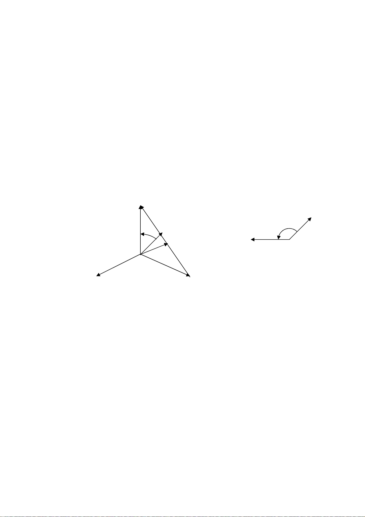
not changed during all tests. It is possible to phase shift the current with respect to voltage;
selections are the following.
. Power-on T-1000: the AC voltage value is displayed.
. There are three ranges available: 65; 130 or 260 V AC; the power is 30 W continuous; 40 W peak
for 1 minute. For increased power and accuracy, it is better to select the range that is closest to the
value to be generated. The default at power-on is 65 V; if necessary, select the desired range. The
operating mode is pre-selected as Fault: do not change it. Do not change also the pre-selected
frequency, as Locked to mains. Last, set the desired current phase angle; however, to perform this,
T-1000 must be ON, and some current must circulate. Selections are performed as follows.
AUX VAC/VDC > Aux Vac control > Range > (Range) RET
Phase > Reference: current > (Phase) ESC
This performed, adjust the voltage to the desired value with knob (20). Eventually, connect the relay
to be tested to sockets (62). Check that the adjusted voltage does not change or the overload
message pops up as you connect the relay; else, this would mean that T-1000 is overloaded (or that
you are connecting to a live wire). In this situation, remove the cause of error and connect again
(reset the alarm if it popped up).
Execute the test, modifying the phase angle as necessary.
This output is also used for the test of voltage relays, frequency relays, synchronism relays;
frequency rate of change relays. In these instances, it is necessary to use the Pre-fault + Fault
selection. This feature allows adjusting two different values: the pre-fault voltage, that simulates the
situation prior to fault, and the fault voltage.
The pre-fault voltage adjustment is performed by the control knob, while knob (20) adjusts the fault
value. Voltage output selection is automatic: pre-fault voltage with test stopped; fault voltage with
test started. The switch from a value to the other one is performed without falling to zero. The main
current or voltage is generated at the zero crossing; the fault one is generated at the meantime of
main voltage or current. The selection of the reference is performed automatically, following the
selection of main output measurement. If the main DC voltage is selected the reference is taken on
the main AC voltage.
MAIN AC CURRENT
(MAIN AC VOLTAGE)
AUXILIARY
VOLTAGE
TEST START
The Pre-fault + Fault selection is performed as follows.
AUX VAC/VDC > Aux Vac control > Mode > Pre-fault+Fault > Pre-fault amplitude ESC
DOC. MIE12093 Rev. 1 Page 14 of 52
Once the nominal voltage is adjusted to the pre-fault value, it is possible to change the amplitude
(V, SYN relays) or frequency (F, SYN relays), or angle (SYN relays: in this instance, the angle is
referred to V main rather than to I main) or frequency rate of change (dF relays) of the fault voltage.
The pre-fault (nominal) frequency is always the mains one; the fault one is adjusted by the control
knob, in the range 40 Hz to 500 Hz. Switching from nominal frequency to fault frequency is
performed without altering the output voltage amplitude and phase. The frequency adjustment is
performed as follows.
AUX VAC/VDC > Aux Vac control > Frequency > Adjust > (Frequency value) ESC
The angle adjustment is performed as explained above; the difference is that the adjustment is
applied only when T-1000 is ON; with the instrument OFF, the pre-fault voltage is normally in
phase with the current. It is also possible to phase shift the pre-fault voltage with respect to the fault
voltage. This parameter is necessary during the test of distance relays, when phase to phase faults
are simulated: as test starts, the auxiliary voltage changes amplitude and phase with respect to the
pre-fault value.
V1 PRE-FAULT
V1 FAULT
FAULT ANGLE
V1 FAULT
PRE-FAULT ANGLE
I1 FAULT
V2 V3
The pre-fault angle adjustment is performed as follows.
AUX VAC/VDC > Aux Vac control > Mode > Pre-fault+Fault > Phase (phase) ESC
This angle is referred to the fault voltage; so, for its adjustment is not necessary to have T-1000 ON.
Last, it is possible to test frequency rate of change relays, by setting both the starting frequency, as
before, and the frequency ROC range, with range from ± 0.01 to ± 99.99 Hz/s. The frequency
change stops at 40 or 70 Hz. The frequency ROC adjustment is performed as follows.
AUX VAC/VDC > Aux Vac control > Frequency > Adjust > Frequency ROC (ROC) ESC
As test starts, the frequency goes to the pre-set frequency, and from that value starts increasing or
decreasing with the pre-set ROC.
1.7 DC VOLTAGE GENERATION FROM THE AUXILIARY OUTPUT
The auxiliary DC voltage is protected by a current limiter. The user notices the low voltage and
removes the overload. The fuse protects the case of counter-feed.

DOC. MIE12093 Rev. 1 Page 15 of 52
The second auxiliary generator can be used to supply the auxiliary DC voltage for the relay to be
tested. To this purpose, the voltage is continuously available at sockets (63). Use this generator as
follows.
. Power-on T-1000: the DC voltage value is displayed.
. There are two ranges available: 130 or 240 V DC; the power is 90 W. For increased power and
accuracy, it is better to select the range that is closest to the value to be generated. The default at
power-on is 130 V; if necessary, select the desired range as follows.
AUX VAC/VDC > Aux Vdc control > (Range) ESC
This performed, adjust the voltage to the desired value. Eventually, connect the relay to be tested to
sockets (63). Check that the adjusted voltage does not change as you connect the relay; else, this
would mean that T-1000 is overloaded (or that you are connecting to a live wire). In this situation, if
it is not a connection error, it is possible to reduce the voltage until the voltage does not drop: relays
tolerate a wide range of DC supply voltages.
1.8 AUXILIARY CONTACT
- The auxiliary make and break contact, closes (opens) at test start, and opens (closes) as current is
cut off after the STOP input is sensed. Maximum time error between current and make/break
contact: 1 ms.
- The contact can also be used to simulate the circuit breaker state. Maximum error between current
start after the trip command and make/break: 1 ms.
- Possibility to delay the auxiliary contact switch with respect to test start. Delay range: from 0 to
99.99 s.
- Contacts range: 5 A; 250 V AC; 120 V DC
1.9 THE TIMER
Timer inputs are protected against wrong selections. If the voltage free input is selected and a
voltage is applied less than 250 V ac or 275 V DC, circuits will not be damaged.
The auxiliary contact is protected by a re-triggering fuse: if it trips, remove the source of the
problem and then restore it.
Characteristics of Start and Stop inputs:
. Inputs do not have any common point, and are opto-coupled from the instrument at 1.35 kV AC;
. Inputs connection: two banana sockets per input;
. Type of input: either clean or under voltage; maximum input: 250V a.c or 275 V DC;
. Inputs may be independently selected as Normal Open or Normal Close or Edge: the latter means
that the timer is stopped by any transition;
. Selections are displayed on the front panel by 10 dedicated lights;
. For both inputs, when the input is closed or with voltage an LED turns on;
. When the relay intervenes the TRIP light turns on.
DOC. MIE12093 Rev. 1 Page 16 of 52
Internal
External
Clean-voltage
N.O.-N.C.-Edge Count
Internal
External
Clean-vo
ltage N.O.-N.C.-Edge
Unit
s (default)
cycles
Count
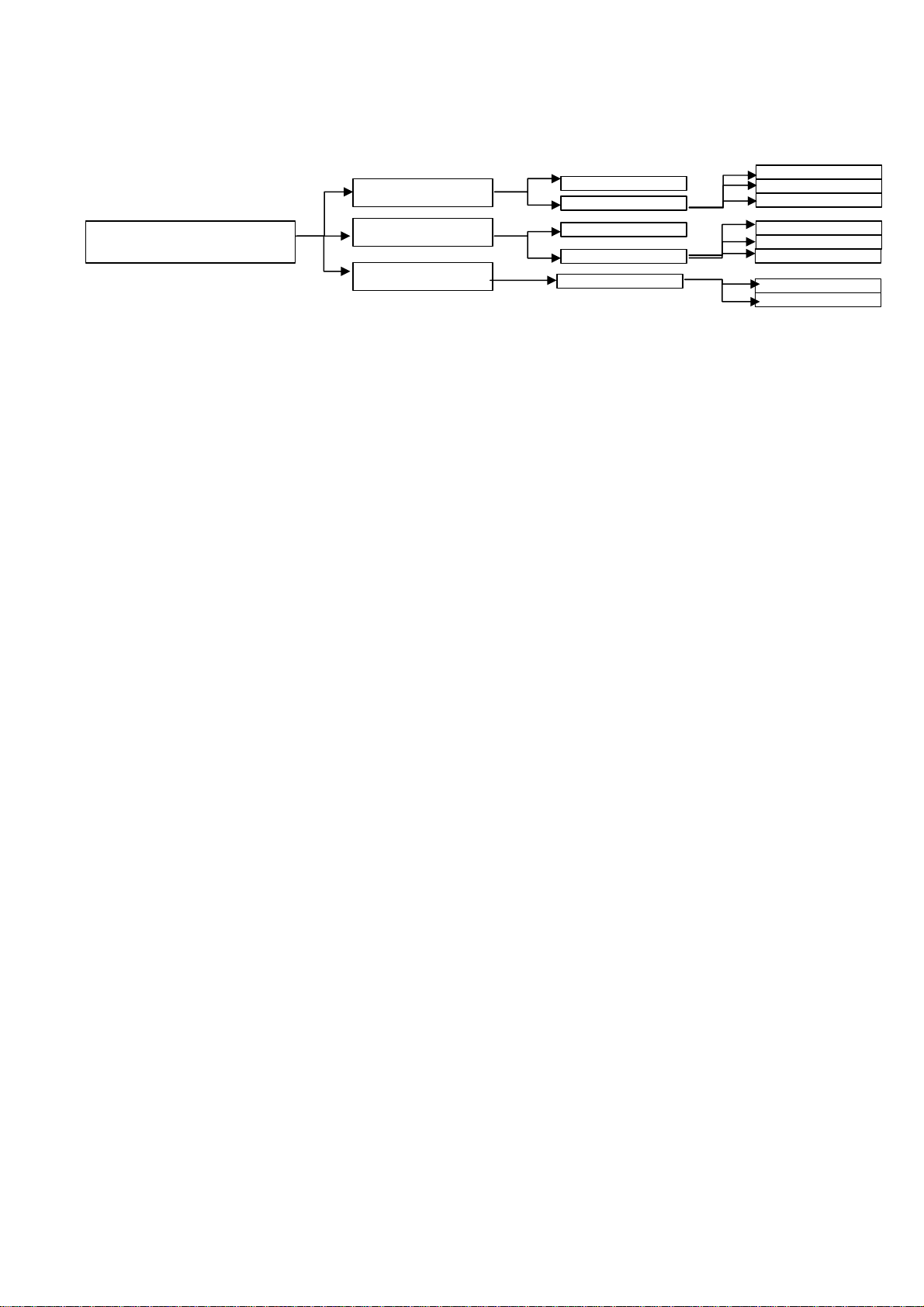
The timer offers a number of possible selections to permit many different types of testing depending
on the selection by the operator. The following flow shows all possible selections.
Start
TIMER START/STOP
Stop
Timer
The default selection is the following.
. Timer start: internal; as test is started. External start allows synchronizing more T-1000.
. Timer stop: external. Internal stop means that the timer is stopped as T-1000 goes OFF.
With this selection, the timer meters the elapsed time between START and STOP. Alternative
selections:
.. Elapsed time plus the duration of STOP input; the selection is performed as follows:
TEST CONTROL > Test mode > Trip + pulse time ESC
.. Impulse counting:: this mode is foreseen for the test of energy meters. Maximum input frequency:
10 kHz; voltage threshold can be set as for tripping. It is possible to select this mode via menu, and
to set the number of impulses; the test set measures the time corresponding to the set number of
complete periods applied to STOP input after ON and during all generation, and measures the
corresponding energy (if selected). The selection is performed as follows:
TIMER START/STOP > STOP > External > Count > (number of counts) ESC
If the count is selected on START, time measurement will be performed after the set number of
counts has expired: this serves to pass the start-up of the energy meter.
Input thresholds. When the contact has voltage applied, two thresholds can be selected. The low
setting applies to nominal voltages of 24 and 48 V; the high setting to 110 V up. The selection is
performed as follows:
TIMER START/STOP > STOP > External > Clean-voltage > Voltage threshold ESC
Time can be metered as seconds or cycles (second is the default). The selection is performed as
follows:
TIMER START/STOP > Units > s or Cycles ESC
1.10 FINDING RELAY THRESHOLDS
1.10.1. Introduction
There are different types of relay characteristic curves: time depending or independent; single
threshold or multiple thresholds. Let us consider the following example, that applies to an
overcurrent relay with a time-dependent curve and one (or more) time-independent threshold. Of
this relay we want to find and save trip and drop-off I> and I>> thresholds.
 Loading...