

Ironwood TSUNO User Manual
0908
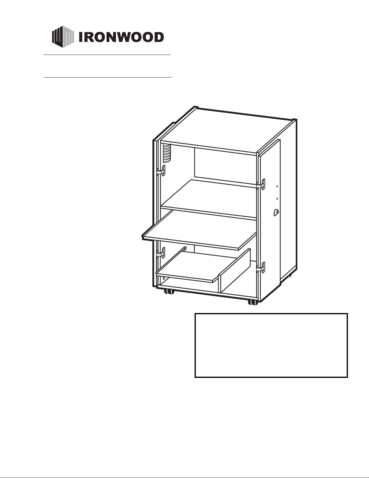
TSU
TOWER
SECURITY UNIT
IMPORTANT!
Assembly may require the assistance of
another person.
Before you begin assembly:
READ THE DIRECTIONS all the way through one
time. This will speed up the process and help you
understand the sequence of steps.
COUNT THE PARTS AND HARDWARE before
assembly. This ensures you have received all
necessary parts before you begin.
TOOLS: You may need a Phillips head screwdriver,
a medium slotted screwdriver or a plastic mallet. To
protect your new furniture from damage during
assembly, it is recommended to work on a
carpeted surface.
CAUTION: On assemblies requiring glue, make
sure the unit is assembled correctly before gluing.
Once this unit is assembled with glue, the
manufacturer will not be responsible for damaged
parts. Keep a damp cloth or sponge handy to wipe
off excess glue.
To care for this furniture, simply wipe with a cloth
dampened with glass cleaner containing ammonia-D.
In the event any parts are missing from
this package, send your name, address,
telephone number, and a description of
the missing part(s) to: PARTS, Box 1420,
Missoula, MT 59806 or call:
1-800-769-5693 or FAX 1-800-445-5281.
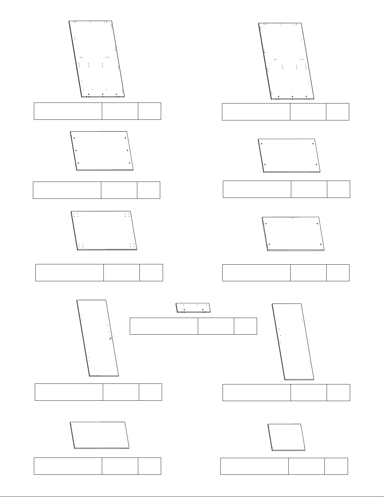
A
PARTS DIAGRAM
B
Left Side 06005641 1 ea.
Right Side 06005641 1 ea.
Top 06005601 1 ea.
Right Door 06005673 1 ea.
Bottom 06005611 1 ea.
Back 06005657 2 ea.
Left Door 06005673 1 ea.
Divider 06005644 1 ea.
Monitor Shelf 06005631 1 ea.
Keyboard Shelf 06005628 1 ea.
Printer Shelf 06005629 1 ea.
C
E
D
G
J
K
L
I
P
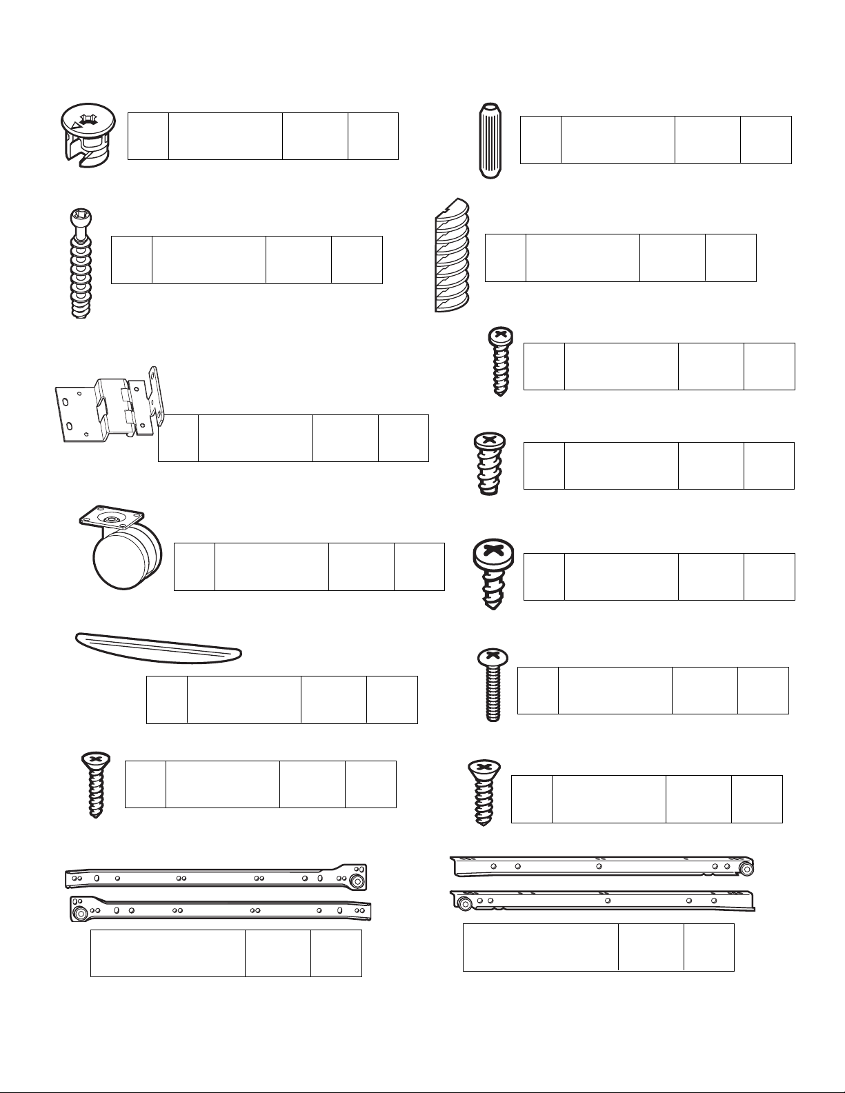
H10
Swivel Casters 402640 4 ea.
H4
CD Rack
286420 2 ea.
H7
Varianta Screw 988060 12 ea.
H2
Wood Dowel 195000 22 ea.
H3
Minifix Bolt 909834 26 ea.
H1
Minifix Cam 909810 26 ea.
H6
Hinge H0590 4 ea.
H11
#14 x 3/4"
Panhead Screw
901241 16 ea.
H13
Door Pull
400800 2 ea.
H14
1" Panhead
Screw
901314 4 ea.
HARDWARE
H5
#6 x 5/8"
Panhead Screw
901216 8 ea.
H16
#6 x 5/8"
Flathead Screw
901120
4 ea.
H17
#8 x 5/8"
Flathead Screw
H2040 36 ea.
Shelf Slide
490260 2 pr.
S4
S3
Slide Channel
490260 2 pr.
S2
S1
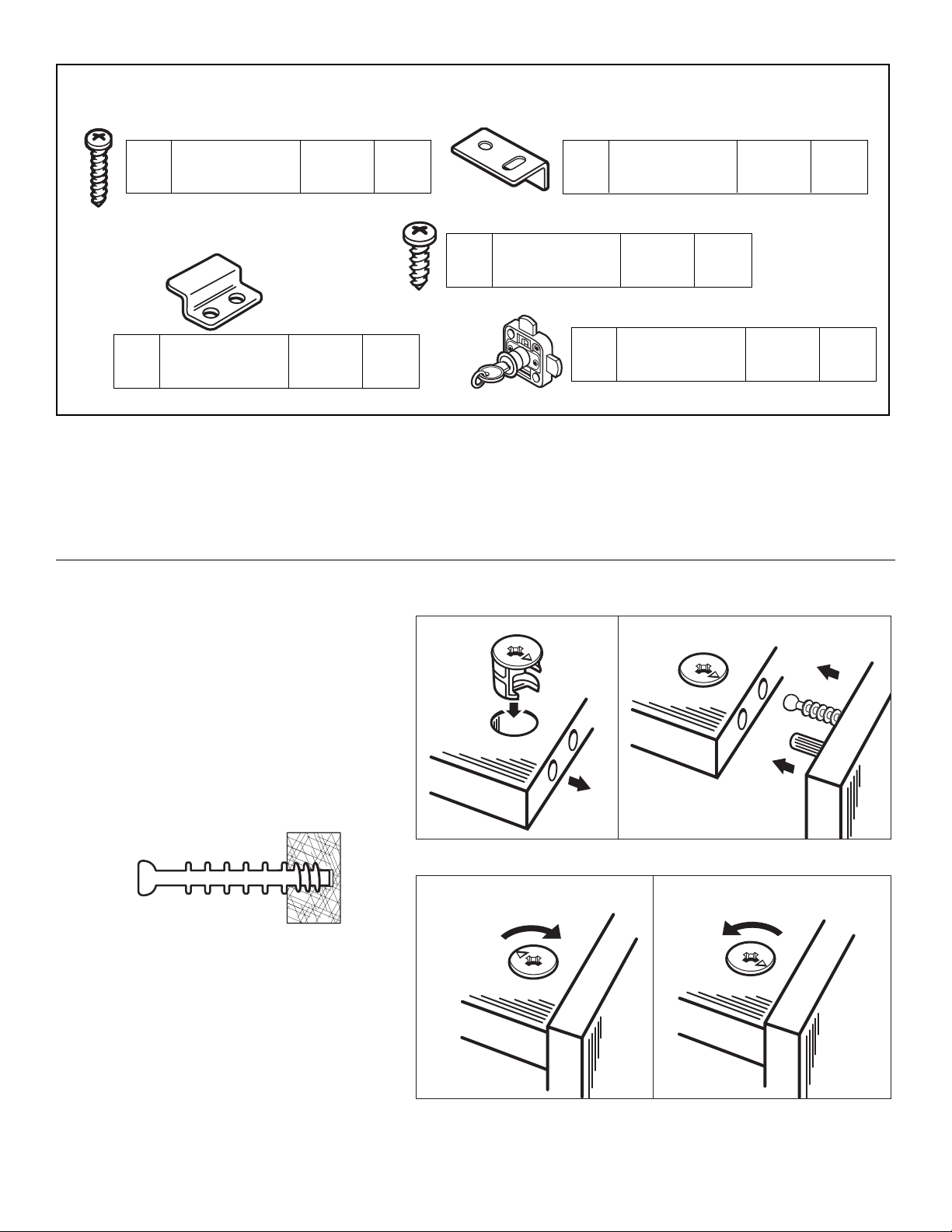
H5
#6 x 5/8"
Panhead Screw
901216 2 ea.
H8
Catch Plate 452340 1 ea.
H9
#8 x 5/8"
Panhead Screw
988056 4 ea.
H12
Stop Plate
452330 1 ea.
LOCKSET 250-HP
H15
Lock & Key Set
452310
452320
452350
1 ea.
1 ea.
1 ea.
Using the Minifix System:
Insert the Minifix Cams into the
appropriate holes with the arrow
facing outwards as shown.
When screwing post into hole, Do
Not over tighten. Screw post down
until bottom face of post flange just
touches board surface.
Using the #2 Phillips screwdriver,
rotate the Cam Devices a half turn
clockwise until snug.
To disassemble, turn the Cam
Devices counter-clockwise and
remove panels.
ASSEMBLED
DISASSEMBLED
Place the Divider (L) on a clean,
carpeted surface with the predrilled holes facing up. Insert two
Minifix Cams (H1) into the
Divider with the arrows of the
cams facing out.
#1
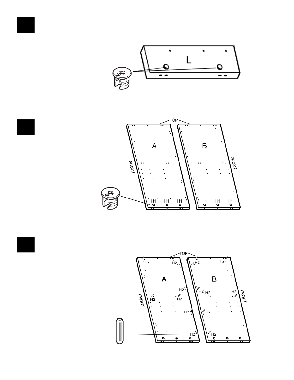
Insert eight Dowels (H2) into each
Side (A & B) where indicated.
#3
Place Left Side (A) and Right
Side (B) with the pre-drilled
holes facing up. Insert three
Minifix Cams (H1) into each
side with the arrows of the
cams facing out.
#2
H1
H1
H2
 Loading...