

Page 1

1112
CDBR
CDBR39
CORNER UNIT
IMPORTANT!
Assembly may require the assistance of
another person.
Before you begin assembly:
READ THE DIRECTIONS all the way through one
time. This will speed up the process and help you
understand the sequence of steps.
COUNT THE PARTS AND HARDWARE before
assembly. This ensures you have received all
necessary parts before you begin.
TOOLS: You may need a Phillips head screwdriver,
a medium slotted screwdriver or a plastic mallet. To
protect your new furniture from damage during
assembly, it is recommended to work on a
carpeted surface.
CAUTION: On assemblies requiring glue, make
sure the unit is assembled correctly before gluing.
Once this unit is assembled with glue, the
manufacturer will not be responsible for damaged
parts. Keep a damp cloth or sponge handy to wipe
off excess glue.
To care for this furniture, simply wipe with a cloth
dampened with glass cleaner containing ammonia-D.
In the event any parts are missing from
this package, send your name, address,
telephone number, and a description of
the missing part(s) to: PARTS, Box 1420,
Missoula, MT 59806 or call:
1-800-769-5693 or FAX 1-800-445-5281.
BY
Page 2
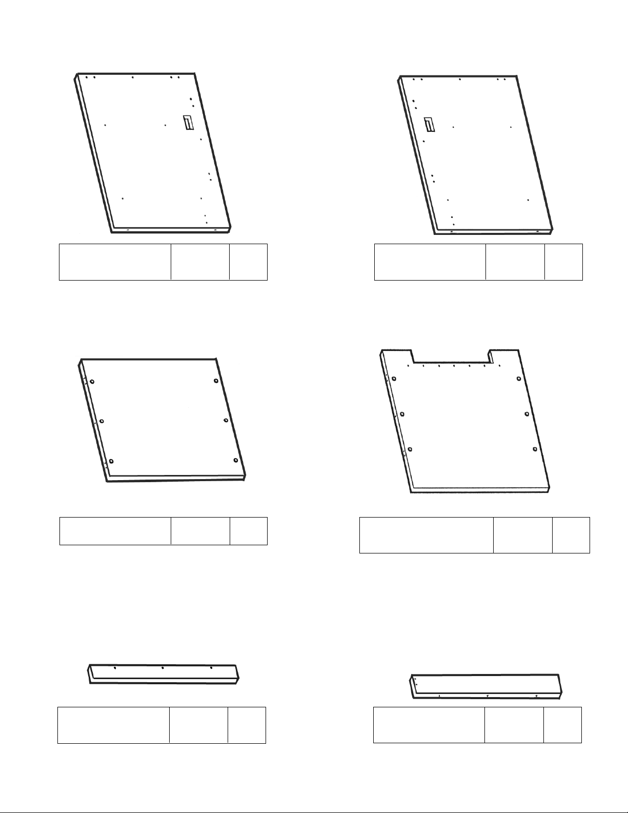
PARTS DIAGRAM
A
B
C
F
D
Left Side - CDBR
Left Side - CDBR39
01010741
01010842
1 ea.
1 ea.
E
Top 01010701 1 ea.
Right Side - CDBR
Right Side - CDBR39
01010741
01010843
1 ea.
1 ea.
Bottom
01010711 1 ea.
Back - CDBR
Back - CDBR39
01010752
01010852
1 ea.
1 ea.
Toeboard
01010172 1 ea.
Page 3
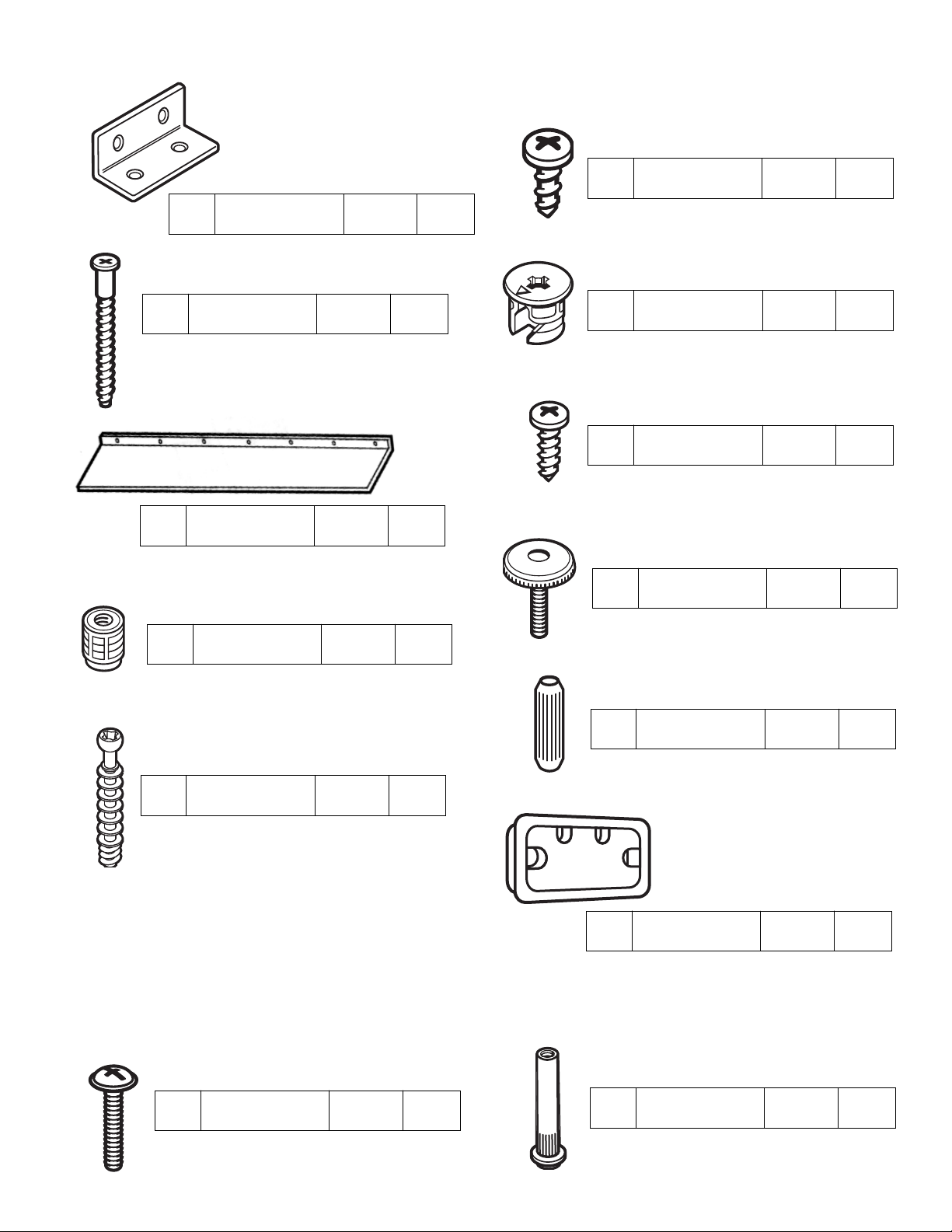
H10
Dowel
195000 8 ea.
H9
Minifix Bolt
909834 12 ea.
H8
Leveler
300870 4 ea.
H4
Minifix Cam
909810 12 ea.
H7
Leveler Insert
274650 4 ea.
H13
Connector
Screw
901350 4 ea.
H11
Grommet
286580 2 ea.
H6
#8 x 5/8" Panhead
Screw
988056 7 ea.
H12
Connector Sleeve
950200 4 ea.
H1
Corner Bracket
411172 2 ea.
H2
#14 x 1/2"
Panhead Screw
901233 8 ea.
H3
Confirmat
Screw
950100 3 ea.
H5
Book Baffle
412370 1 ea.
HARDWARE
Hardware for Attaching to Another Unit
Page 4
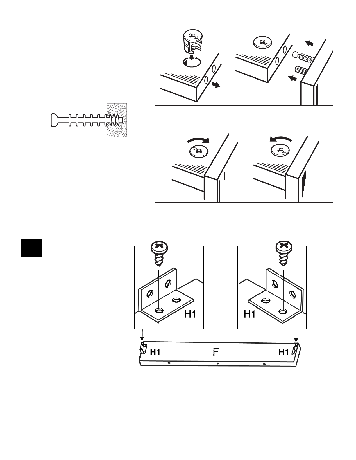
ASSEMBLED
DISASSEMBLED
Using the Minifix System:
Insert the Minifix Cams into the
appropriate holes with the arrow
facing outwards as shown.
Using the #2 Phillips screwdriver,
rotate the Cam Devices a half turn
clockwise until snug.
To disassemble, turn the Cam
Devices counter-clockwise and
remove panels.
When screwing post into hole, Do
Not over tighten. Screw post down
until bottom face of post flange just
touches board surface.
Secure an Angle
Bracket (H1) to each
end of the Toeboard (F)
using four #14x½"
Panhead Screws (H2).
#1
H2
H2
Page 5
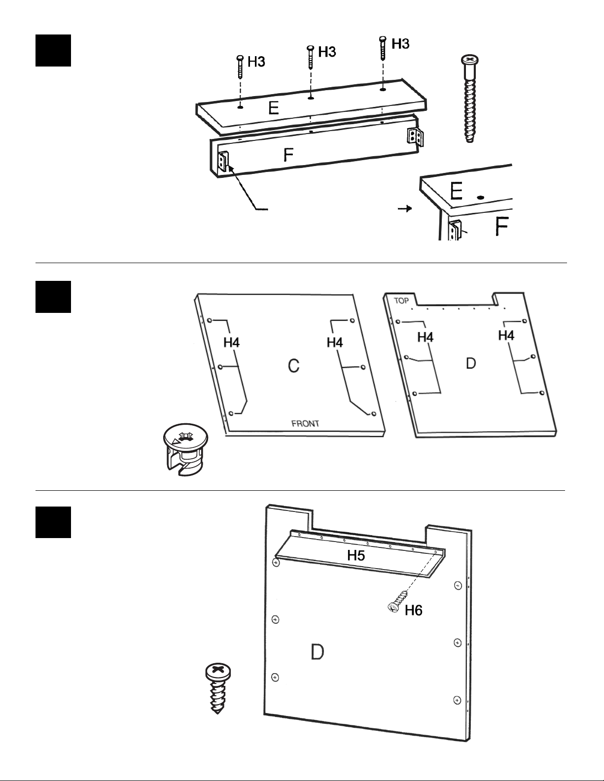
#2
#3
Attach the Book Baffle (H5
to the Back (D) using seven
#8 x 5/8" Panhead Screws
(H6) in the pre-drilled holes
as shown.
#4
Attach the Toeboard (F) to
the Bottom (E) using three
Confirmat Screws (H3)
through the pre-drilled
holes as shown.
Insert six Minifix Cams
(H4) into the Top (C)
and Back (D) with the
arrows of the cams
facing out.
H6
H4
NOTE: The Angle
Bracket should be
oriented as shown.
H3
Page 6
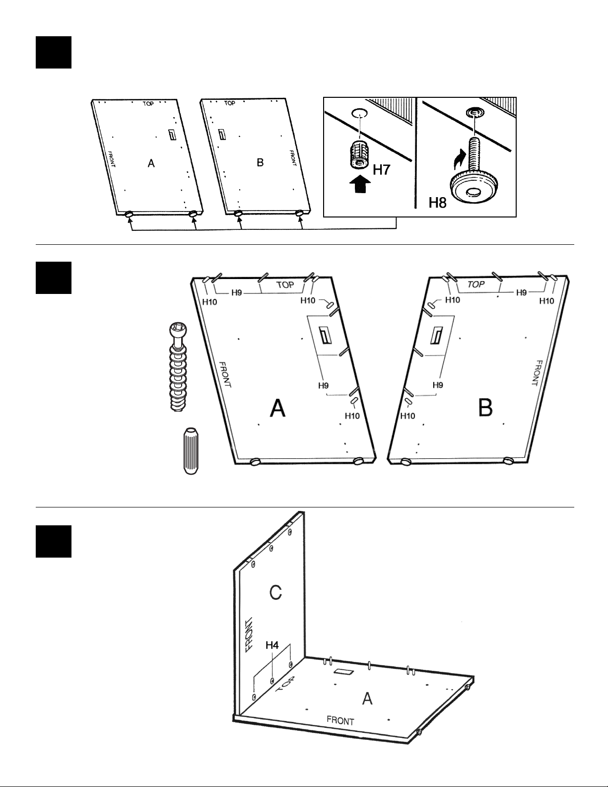
Insert the Leveler Inserts (H7) into the holes in the bottom edges of each Side. Using
a plastic mallet, tap until flush with the surface. Screw the Levelers (H8) into the
Leveler Inserts. Adjust Levelers when the assembled unit is in place.
#5
Screw six Minifix
Bolts (H9) into each
Side (A & B) where
indicated.
Insert four Dowels
(H10) into each side
(A & B) where
indicated.
#6
Place the Left Side (A) with the
bolts and dowels facing up as
shown. Position the Top (C)
onto the Left Side and turn
cams (H4) clockwise to secure.
Note: Make sure the front
edges are located as shown.
#7
H9
H10
Page 7
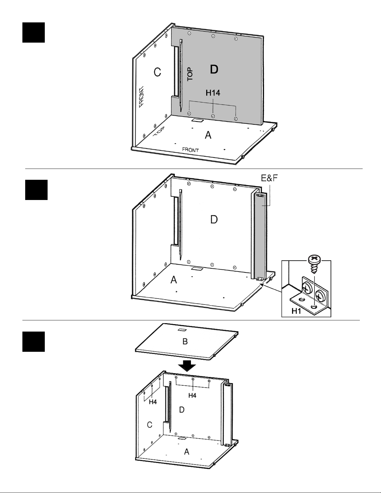
Position the Back (D) onto
the Left Side (A) and turn
the cams (H4) clockwise
to secure.
#8
Position the Bottom and
Toeboard (E & F) onto the
Left Side (A). Secure in
place using two #14x½"
Panhead Screws (H2)
through the Angle Bracket
(H1) into the pre-drilled
holes of the Left Side (A).
#9
Position the bolts and
dowels of the Right Side
(B) onto the unit and turn
the cams (H4) clockwise
to lock in place.
#10
H2
Page 8
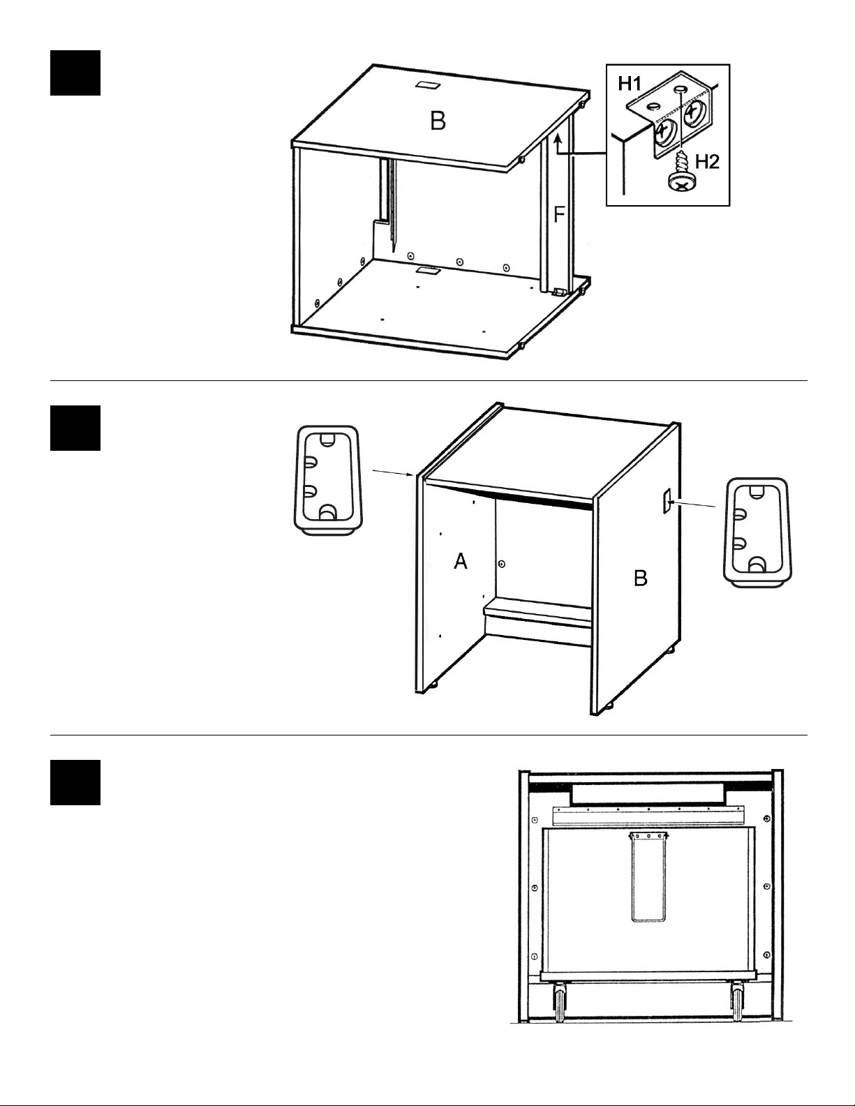
Secure the other Angle
Bracket (H1) of the
Toeboard (F) to the Right
Side (B) using #14x½"
Panhead Screws (H2).
#11
With the assistance of
another person, turn the unit
upright. Insert Grommets
(H11) into the Left Side (A)
and Right Side (B) as shown.
#12
When placing the Book Cart into the Book Return unit,
leave equal spacing between sides and push the cart all
the way in and under the book baffle.
#13
H11
H11
Your Glacier Circulation Corner Unit is
now fully assembled and ready for use.
Page 9
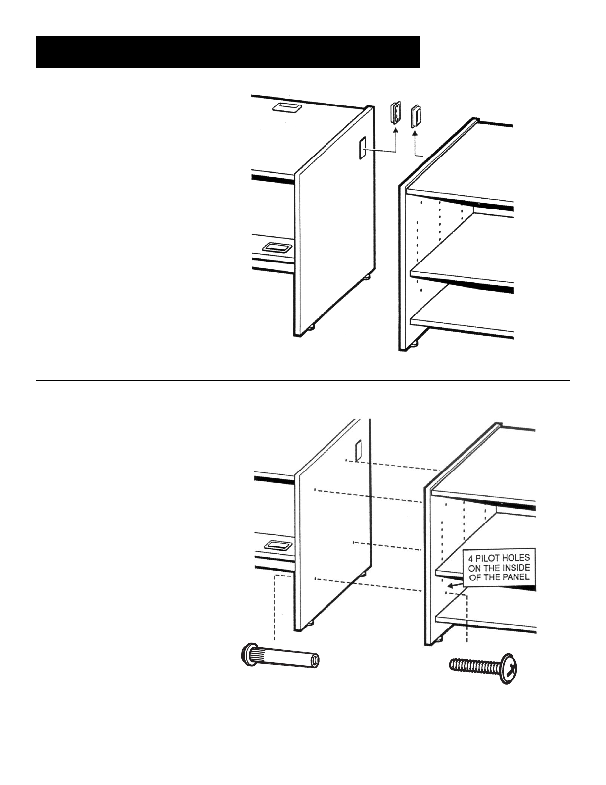
CONNECTING TO OTHER CIRCULATION DESK UNITS:
Remove Grommets from
the panels to be connected.
Using a 13/64" bit, drill through
the four pilot holes on the inside
of each side panel.
Align the side panels of the units
to be connected. Tap four
Connector Sleeves (H12)
through the holes in one side
panel and into the holes of the
unit to be connected. From the
other side, secure the units
together using four Connector
Screws (H13).
H12
H13
 Loading...