

Ironwood LSCGG User Manual
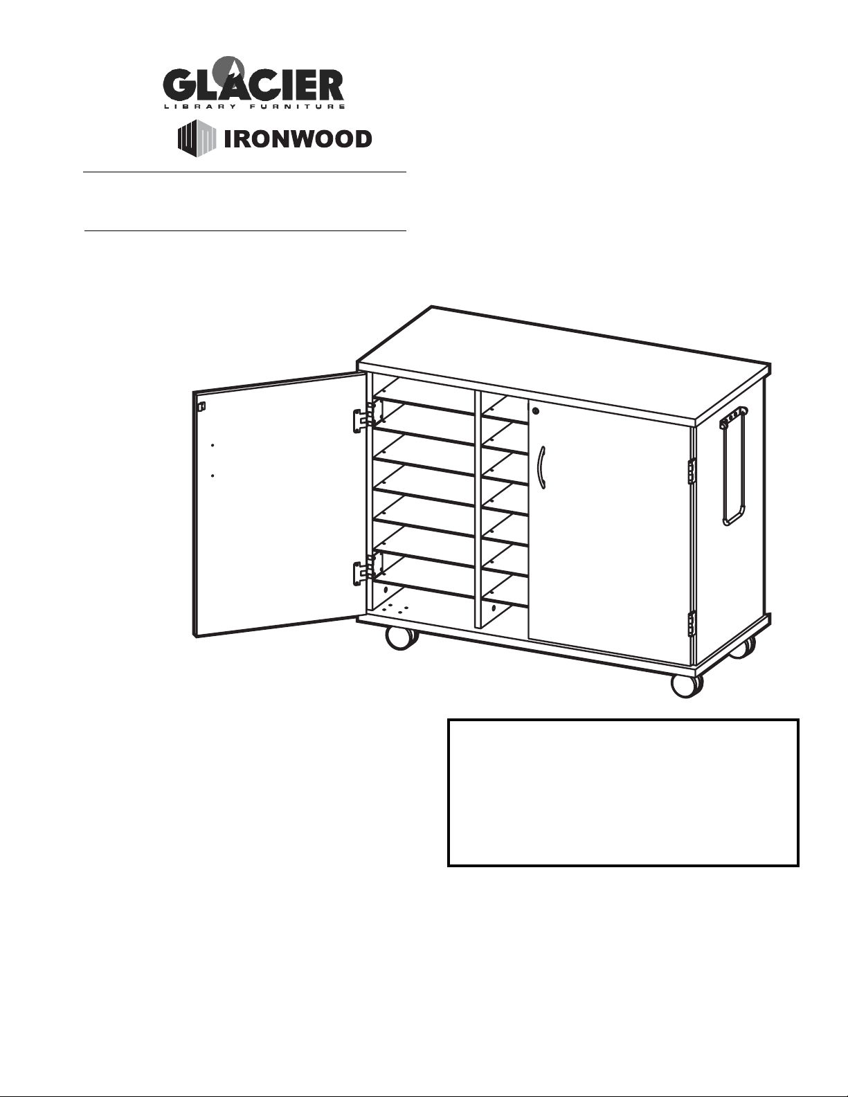
LSC
LAPTOP STORAGE
CART
IMPORTANT!
Assembly may require the assistance of
another person.
Before you begin assembly:
READ THE DIRECTIONS all the way through one
time. This will speed up the process and help you
understand the sequence of steps.
COUNT THE PARTS AND HARDWARE before
assembly. This ensures you have received all
necessary parts before you begin.
TOOLS: You may need a Phillips head screwdriver,
a medium slotted screwdriver or a plastic mallet. To
protect your new furniture from damage during
assembly, it is recommended to work on a
carpeted surface.
CAUTION: On assemblies requiring glue, make
sure the unit is assembled correctly before gluing.
Once this unit is assembled with glue, the
manufacturer will not be responsible for damaged
parts. Keep a damp cloth or sponge handy to wipe
off excess glue.
To care for this furniture, simply wipe with a cloth
dampened with glass cleaner containing ammonia-D.
In the event any parts are missing from
this package, send your name, address,
telephone number, and a description of
the missing part(s) to: PARTS, Box 1420,
Missoula, MT 59806 or call:
1-800-769-5693 or FAX 1-800-445-5281.
BY
0808
L (1 ea)
M (1 ea)
G (21 ea)
A B
C
J (2 ea)
E
D
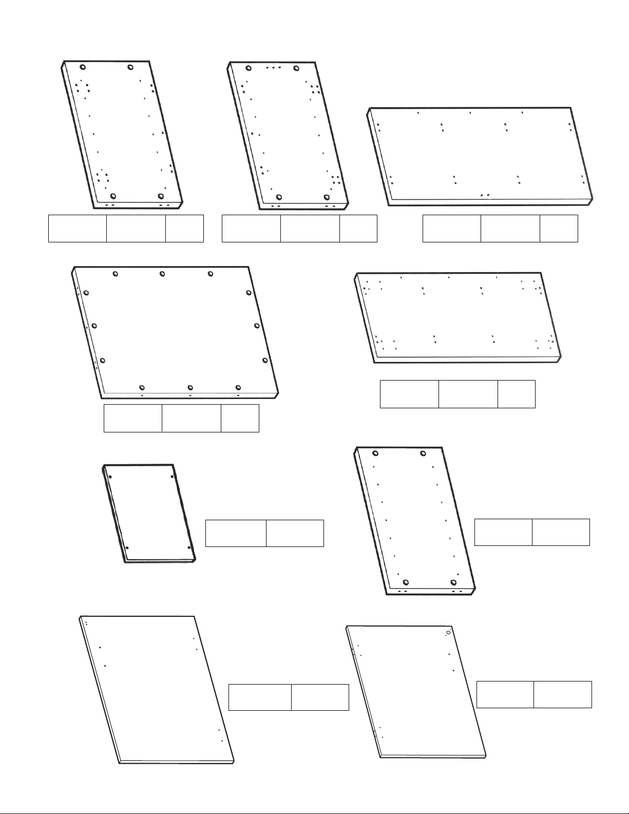
PARTS DIAGRAM
Adjustable
Shelf
01050127
Divider
01050144
Left Door
01050173
Right Door
01050173
Top 01050101 1 ea.Right Side 01050141 1 ea.Left Side 01050141 1 ea.
Bottom 01050111 1 ea.
Back 01050152 1 ea.
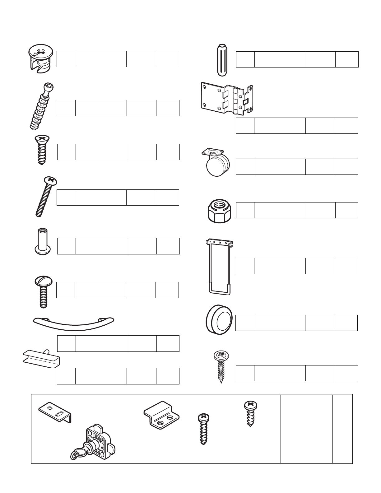
H6
Swivel Caster 402640 4
H9
Barrel Nut 902200 3
H1
Minifix Cam
908810
28
H2
Wood Dowel 195000 20
H8
Nylok Nut 904420 16
H17
1" Washerhead
Screw
920200 4
H12
Door Bumper 298032 4
H20
Panel Clip H0981 84
H10
Pull Handle 490670 1
H3
Minifix Bolt 909834 28
H7
Long Machine
Screw
902201 16
H16
Door Pull 400870 2
H4
Hinge H0523 4
H11
Short Machine
Screw
901303 3
H5
#8 x5/8”
Flathead Screw
H2040 32
H18
Lockset 250-HP
1 set
H15
Lock and
Key Set
1 ea.
#8-5/8” Panhead
4 ea.
H14
#6-3/4” Panhead
2 ea.
Catch Plate
1 ea.
H13
H19
Door Plate
1 ea.
HARDWARE
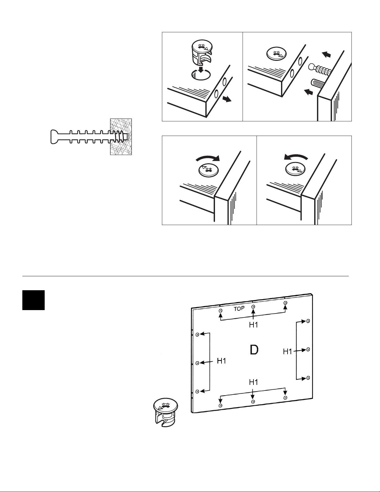
Using the Minifix System:
Insert twelve Minifix Cams (H1)
into the Back (D) with the arrows
of the cams facing out.
#1
H1
Insert the Minifix Cams into the
appropriate holes with the arrow
facing outwards as shown.
When screwing post into hole, Do
Not over tighten. Screw post down
until bottom face of post flange just
touches board surface.
Using the #2 Phillips screwdriver,
rotate the Cam Devices a half turn
clockwise until snug.
To disassemble, turn the Cam
Devices counter-clockwise and
remove panels.
ASSEMBLED
DISASSEMBLED
 Loading...