

Ironwood LFPDOC User Manual

08/06
LIBRARY FURNITURE
LFPD
PAPERBACK
DISPLAY
IMPORTANT!
Assembly may require the assistance of
another person.
Before you begin assembly:
READ THE DIRECTIONS all the way through one
time. This will speed up the process and help you
understand the sequence of steps.
COUNT THE PARTS AND HARDWARE before
assembly. This ensures you have received all
necessary parts before you begin.
TOOLS: You may need a Phillips head screwdriver,
a medium slotted screwdriver or a plastic mallet. To
protect your new furniture from damage during
assembly, it is recommended to work on a
carpeted surface.
CAUTION: On assemblies requiring glue, make
sure the unit is assembled correctly before gluing.
Once this unit is assembled with glue, the
manufacturer will not be responsible for damaged
parts. Keep a damp cloth or sponge handy to wipe
off excess glue.
To care for this furniture, simply wipe with a cloth
dampened with glass cleaner containing ammonia-D.
In the event any parts are missing from
this package, send your name, address,
telephone number, and a description of
the missing part(s) to: PARTS, Box 1420,
Missoula, MT 59806 or call:
1-800-769-5693 or FAX 1-800-445-5281.
BY

Left Panel 07010742 1 ea.
A
B
Right Panel 07010742 1 ea.
Toeboard 07010772 1 ea.
Sloped Back
07010755 1 ea.
Back
Spanner
07010760 1 ea.
Fixed/Adj.
Shelf
07010724 5 ea.
PARTS DIAGRAM
Minifix Bolt 909834 16 ea.
H3
Minifix Cam 909810 16 ea.
H2
Wood Dowel 195000 8 ea.
H1
PARTS DIAGRAM
Screw In Tab V
909931 4 ea.
H4
Push In Tab V 909932 16 ea.
H5
Tab V Housing 909930 20 ea.
H6
Varianta
Screw
988060 4 ea.
H7
C
E
D
F
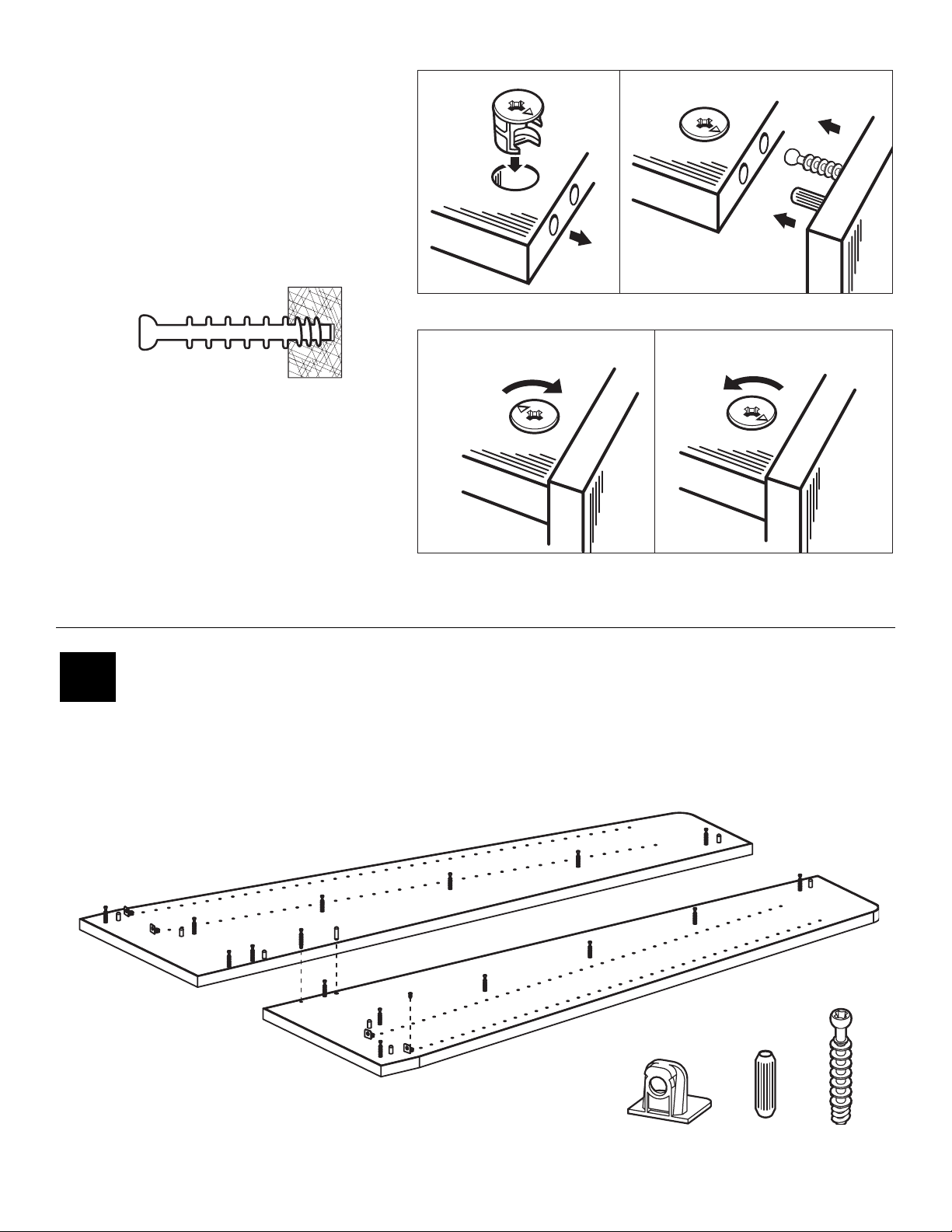
Using the Minifix System:
#1
Insert Wood Dowels (H1) into holes, screw in Minifix Bolts (H3)
into corresponding holes. Line up and screw in Tab V (H4) and
screw into place with Varianta Screw (H7).
H4
H3
H1
Insert the Minifix Cams into the
appropriate holes with the arrow
facing outwards as shown.
When screwing post into hole, Do
Not over tighten. Screw post down
until bottom face of post flange just
touches board surface.
ASSEMBLED
Using the #2 Phillips screwdriver,
rotate the Cam Devices a half turn
clockwise until snug.
To disassemble, turn the Cam
Devices counter-clockwise and
remove panels.
DISASSEMBLED
H3
H1
H4
H1
H3
H3
H3
H1
H3
H1
H4
A
H3
H3
H7
H3
B
H3
H3
H3
H3
H1
H1
H3
 Loading...