


0307
ECW32/39
COMPUTER
WORKSTATION
IMPORTANT!
Assembly may require the assistance of
another person.
Before you begin assembly:
READ THE DIRECTIONS all the way through one
time. This will speed up the process and help you
understand the sequence of steps.
COUNT THE PARTS AND HARDWARE before
assembly. This ensures you have received all
necessary parts before you begin.
TOOLS: You may need a Phillips head screwdriver,
a medium slotted screwdriver or a plastic mallet. To
protect your new furniture from damage during
assembly, it is recommended to work on a
carpeted surface.
CAUTION: On assemblies requiring glue, make
sure the unit is assembled correctly before gluing.
Once this unit is assembled with glue, the
manufacturer will not be responsible for damaged
parts. Keep a damp cloth or sponge handy to wipe
off excess glue.
To care for this furniture, simply wipe with a cloth
dampened with glass cleaner containing ammonia-D.
In the event any parts are missing from
this package, send your name, address,
telephone number, and a description of
the missing part(s) to: PARTS, Box 1420,
Missoula, MT 59806 or call:
1-800-769-5693 or FAX 1-800-445-5281.
BY
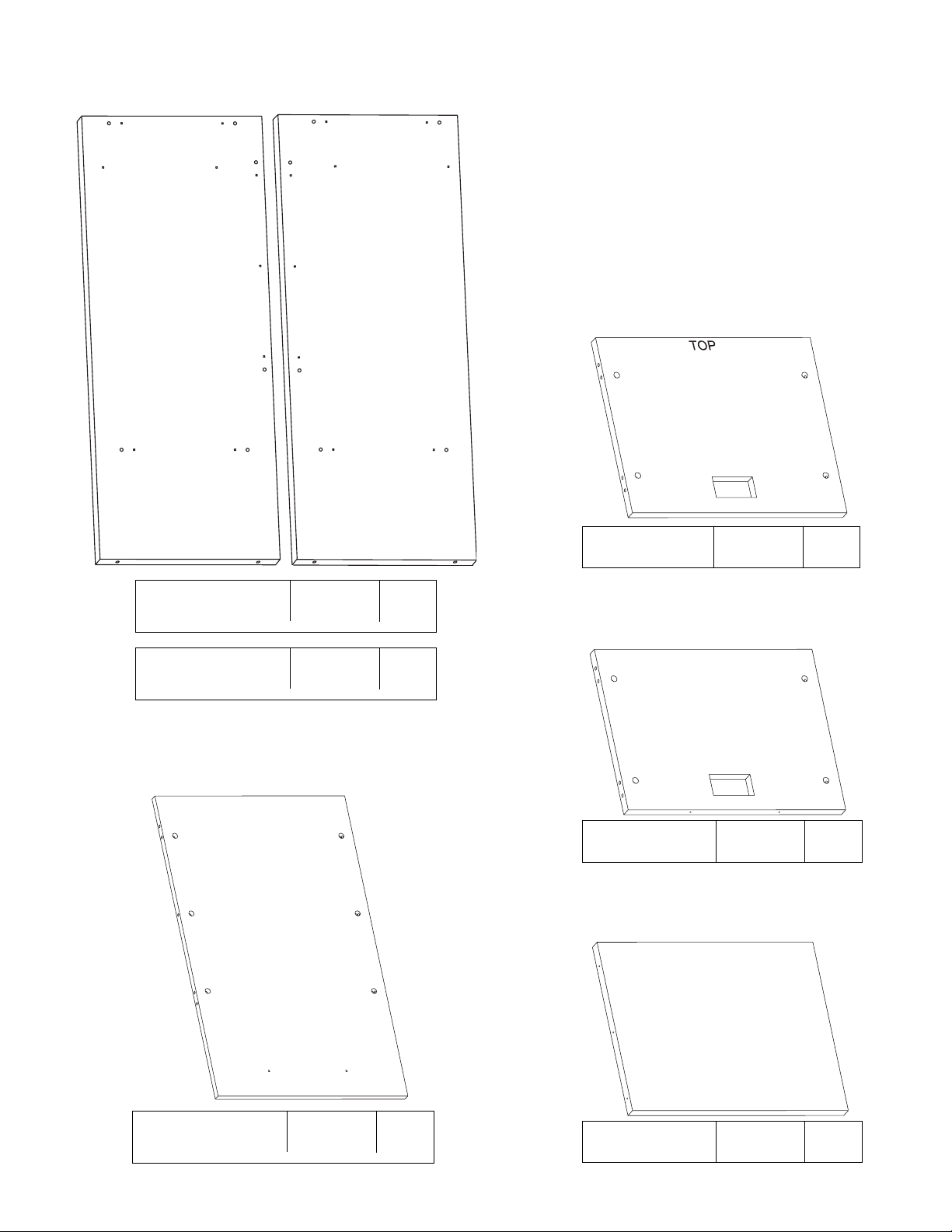
PARTS DIAGRAM
Top 01070301 1 ea.
Left Side - ECW32
Left Side - ECW39
01070341
01070441
1 ea.
1 ea.
Back - ECW32
Back - ECW39
01070352
01070452
1 ea.
1 ea.
Fixed Shelf 01070328 1 ea.
Keyboard Shelf -
EC32
01070328 1 ea.
Right Side - ECW32
Right Side - ECW39
01070341
01070441
1 ea.
1 ea.
FRONT
FRONT
TOP
TOP
A
A
TOP
FRONT
B
C
TOP
D
FRONT
E
K
FRONT
H3
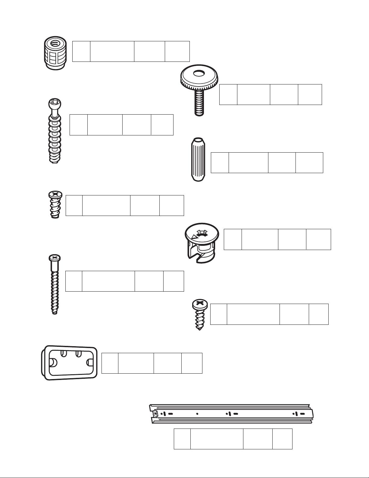
Minifix Bolt 909834 14 ea.
H2
Leveler 300870 4 ea.
H1
Leveler Insert
274650
4 ea.
H6
Minifix Cam 909810 14 ea.
H4
Wood Dowel 195000 12 ea.
H5
Varianta Screw 4 ea.
988060
H7
Confirmat Screw 2 ea.
950100
H8
#8 x 5/8”
Panhead Screw
6 ea.
988056
H9
Grommet 2 ea.
286580
S
Full Extension
Slide
1 pr.
490420

Place the Left Side (A) and the Right Side (B) on a clean, carpeted surface as shown.
Install Glide Inserts (H1) into the bottom holes of the Left Side and Right Side and tap
until flush with the surface. Screw the short Glides (H2) into the Glide Inserts.
Adjust the Short Glides after assembly is complete.
#1
Using the Minifix System:
Insert the Minifix Cams into the
appropriate holes with the arrow
facing outwards as shown.
When screwing post into hole, Do
Not over tighten. Screw post down
until bottom face of post flange just
touches board surface.
Using the #2 Phillips screwdriver,
rotate the Cam Devices a half turn
clockwise until snug.
To disassemble, turn the Cam
Devices counter-clockwise and
remove panels.
ASSEMBLED
DISASSEMBLED

#2
Screw seven Minifix bolts (H3) and
insert six Wood Dowels (H4) into the
Side Panels (A and B) where indicated.
H3
H4
Attach a Full Extension Slide (S) to the Left Side
(A) using two Varianta Screws (H5) as shown.
It will be necessary to slide the sliding
portion forward to access the 2nd hole.
#3
#4
Attach a Full Extension Slide (S) to Right Side (B)
using two Varianta Screws (H5) as shown.
It will be necessary to slide the sliding portion
forward to access the 2nd hole.

Place the Back (D), Fixed Shelf (E), and Top (C) as
shown. Insert fourteen Minifix Cams (H6) into the holes
where indicated with the arrows of the cams facing out.
#5
#6
H6
Position the Top (C) onto the Left Side (A) as shown.
Turn the arrows of the indicated Minifix Cams (H6) of
the Top clockwise to secure in place.
Position the Fixed Shelf (E) onto the unit
as shown. Turn the arrows of the cams
(H6) of the Fixed Shelf (E) clockwise to
secure in place.
#8
Position the Back (D) onto the Left Side
(A) as shown. Turn the arrows of the
indicated Minifix Cams (H6) of the Back
clockwise to secure in place.
#7

Secure the Fixed Shelf (E) to the Back (D)
using two Confirmat Screws (H7) as
shown.
#9
#10
Position the Right Side (B) onto the
assembly as shown and turn the cams of
the Top (C), Back (D), and the Fixed Shelf
(E) clockwise to secure in place.
Attach the Slider Channel portion of the
Full Extension Slide (S) to the left side of
the Keyboard Shelf (K) using #8 x 5/8”
Panhead Screws (H8) as shown.
Be sure that the long arm of the locking clip
points toward the front of the Keyboard
Shelf (and is on the bottom).
#12
H7
Remove the Slider Channel Section from the Slide Rail which was attached to
the Left and Right Side panels in Steps 3 and 4:
1. extend the slide completely,
2. push the arm of the locking clip up and
3. pull the channel section forward until disconnected as shown.
#11
LOCKING
CLIP ARM
MAIN PORTION
OF SLIDE
CHANNEL
SECTION
LOCKING
CLIP ARM

Attach the remaining Slider Channel portion
of the Full Extension Slide (S) to the right
side of the Keyboard Shelf (K) using #8 x
5/8” Panhead Screws (H8) as shown.
Be sure that the long arm of the locking clip
points toward the front of the Keyboard
Shelf (and is on the top).
#13
Insert Grommets (H9) into the Top (C) and the
Fixed Shelf (E) as shown.
#15
Extend the cabinet portions of the Full Extension
Slides (S) completely out. Slide the channels of the
Keyboard Shelf (K) onto the slides of the cabinet as
shown until secured by the locking clips.
#14
Your ECW Computer Workstation is now fully assembled and ready for use.
H9
 Loading...