

0307
IMPORTANT!
Assembly may require the assistance of
another person.
Before you begin assembly:
READ THE DIRECTIONS all the way through one
time. This will speed up the process and help you
understand the sequence of steps.
COUNT THE PARTS AND HARDWARE before
assembly. This ensures you have received all
necessary parts before you begin.
TOOLS: You may need a Phillips head screwdriver,
a medium slotted screwdriver or a plastic mallet. To
protect your new furniture from damage during
assembly, it is recommended to work on a
carpeted surface.
CAUTION: On assemblies requiring glue, make
sure the unit is assembled correctly before gluing.
Once this unit is assembled with glue, the
manufacturer will not be responsible for damaged
parts. Keep a damp cloth or sponge handy to wipe
off excess glue.
To care for this furniture, simply wipe with a cloth
dampened with glass cleaner containing ammonia-D.
In the event any parts are missing from
this package, send your name, address,
telephone number, and a description of
the missing part(s) to: PARTS, Box 1420,
Missoula, MT 59806 or call:
1-800-769-5693 or FAX 1-800-445-5281.
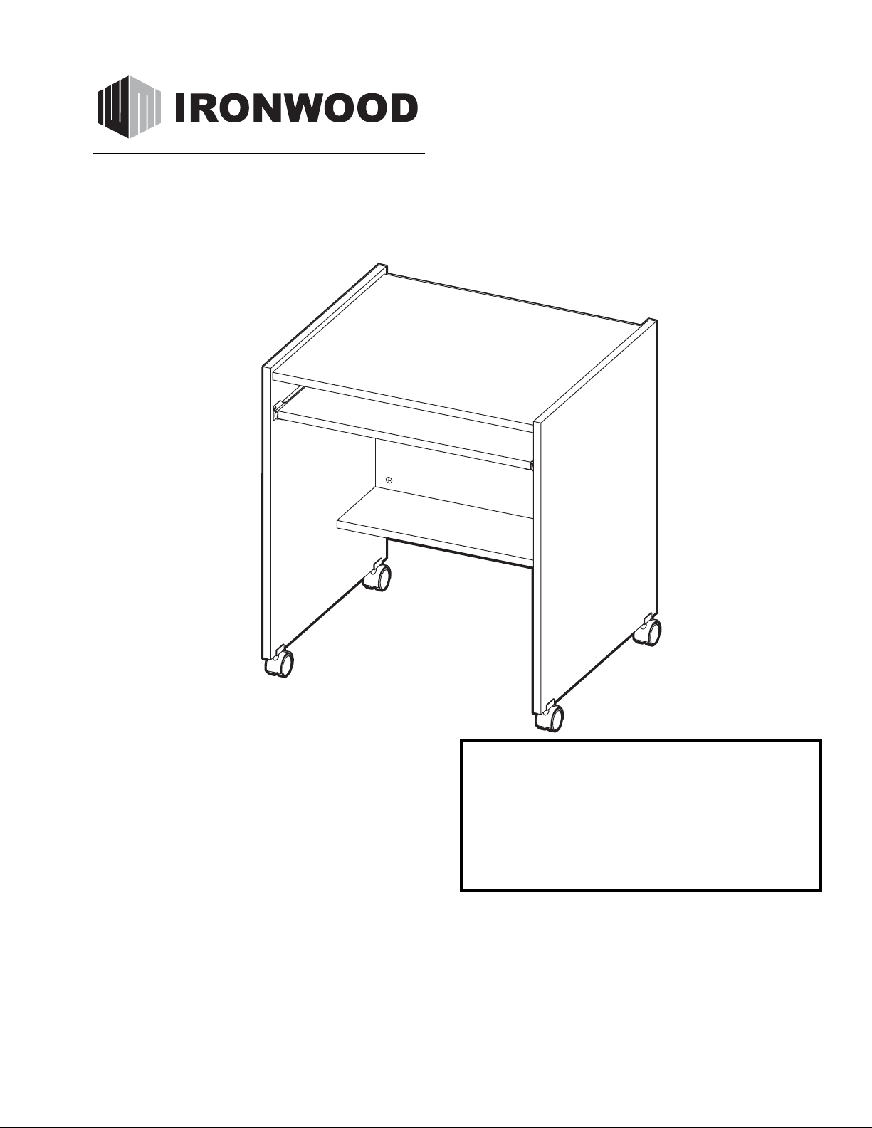
CUB
COMPUTER STAND

PARTS DIAGRAM
C (1 ea)
To p
05840301
D (1 ea)
Back
05841352
A (1 ea)
Left Side
05841341
B (1 ea)
Right Side
05841341
G (1 ea)
Storage
Shelf
05840332
K (1 ea)
Keyboard
Shelf
05840328
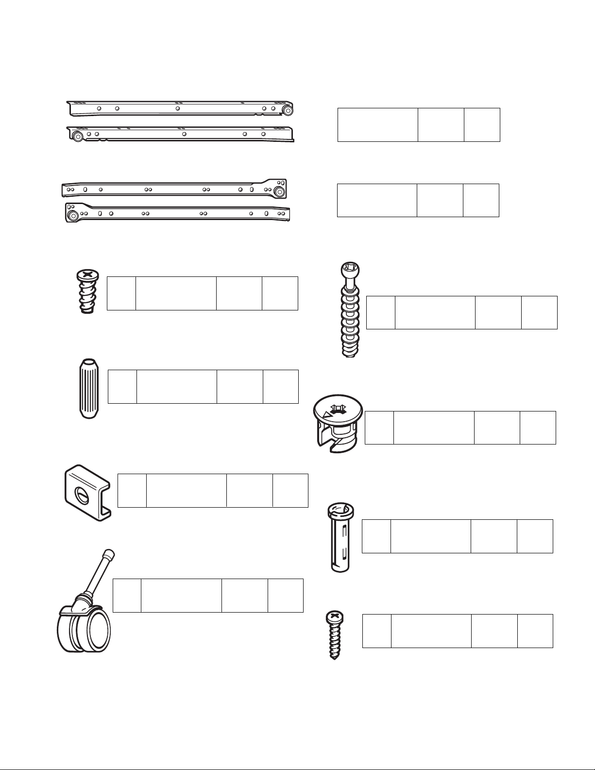
H2
Minifix Bolt 909834 12 ea.
H7
Stem Caster 402290 4 ea.
H4
Minifix Cam 909810 12 ea.
H1
Varianta Screw 988060 6 ea.
H3
Wood Dowel 195000 6 ea.
Drawer Slide 490260 1 pr.
Slide Channel 490260 1 pr.
H5
Caster Bracket 402303 4 ea.
H8
Panhead Screw 901216 4 ea.
H6
Caster Socket 402301 4 ea.
S4
S2
S3
S1
HARDWARE

Using the Minifix System:
Attach a left Side Channel (S1) to
Left Side (A) using Varianta Screws
(H1) in the selected pre-drilled
holes as shown.
#1
H1
Insert the Minifix Cams into the
appropriate holes with the arrow
facing outwards as shown.
When screwing post into hole, Do
Not over tighten. Screw post down
until bottom face of post flange just
touches board surface.
Using the #2 Phillips screwdriver,
rotate the Cam Devices a half turn
clockwise until snug.
To disassemble, turn the Cam
Devices counter-clockwise and
remove panels.
ASSEMBLED
LAST HOLE
AT END
S2
DISASSEMBLED
6TH HOLE
FROM
ROLLER
2ND HOLE
FROM
ROLLER
H1
B

#3
#4
Place the Right Side (B) with the pre-drilled holes
facing up as shown. Screw Minifix Bolts (H2) into
the indicated holes as shown.
Insert three Wood Dowels (H3) into the indicated
holes as shown.
H2
H2
H3
H3
B
#2
Attach a right Side Channel (S2) to Right
Side (B) using Varianta Screws (H1) in
the selected pre-drilled holes as shown.
Place the Left Side (A) with the pre-drilled holes
facing up as shown. Screw Minifix Bolts (H2) into the
indicated holes as shown.
Insert three Wood Dowels (H3) into the indicated
holes as shown.
H3
H2
H3
H2
H1
2ND HOLE
FROM
ROLLER
H1
6TH HOLE
FROM
ROLLER
A
H3
LAST HOLE
AT END
S2
H2
A
H2
H3

#5
Insert Minifix Cams (H4) into the
Worksurface (C) with the arrows
of the cams facing out as shown.
#6
H4
Position the Worksurface (C) onto
the bolts of the Left side (A) and
turn the Minifix Cams (H4) clockwise to secure in place.
H4
C
H4
C
H4
A

#7
#8
Insert Minifix Cams (H4) into the
Storage Shelf (G) with the arrows of the
cams facing out. Position the Storage
Shelf onto the bolts of the Left Side (A)
and turn the Minifix Cams clockwise to
secure in place.
H4
H4
Insert Minifix Cams (H4) into the
Back (D) with the arrows of the cams
facing out. Position the Back onto the
bolts of the Left Side (A) and turn the
Minifix Cams clockwise to secure in
place.
H4
D
C
H4
A
C
A
D
H4
G
H4

Insert the Casters (H7) into the
Caster Sockets and tap into place.
#11
Position the Caster Brackets (H5) over the
corresponding holes in the bottom edges of
the Sides. Insert Caster Sockets (H6) into
the holes and tap until bottomed out against
the Caster Brackets.
#10
#9
Position the bolts and dowels of the
Right Side (B) into the corresponding
Cams of the partially assembled unit.
Rotate the arrows of the Minifix Cams
(H4) clockwise to secure in place.
H4
C
B
H4
D
H4
G

#13
#12
Place the Keyboard Shelf (K)
with pre-drilled holes facing up
as shown. Attach left and right
Shelf Slides (S3 & S4) using the
Panhead Screws (H8) as shown.
3RD HOLE
FROM
ROLLER
END
3RD HOLE
FROM
ROLLER
END
3RD HOLE
FROM FRONT
3RD HOLE
FROM FRONT
ROLLER
END
FRONT
FINISHED
EDGE
Insert the Keyboard Shelf (K) into the
upper set of Side Channels as shown.
H8
H8
S3
K
H8
H8
S4
K

#14
Your CUB Computer Buddy is now
completely assembled and ready for use.
 Loading...