

Page 1

StatSpin® Express 4 Horizontal Centrifuge
Operator’s Manual
A Division of IRIS International, Inc.
Page 2

Operator’s Manual
StatSpin® Express 4
Horizontal Centrifuge
Model Number M510
For in-vitro diagnostic use
Product Number
SSH4 – StatSpin
®
Express 4 for 100-240 VAC, 50/60 Hz
StatSpin and Iris are registered trademarks of IRIS International, Inc.
Copyright 2010
Printed in U.S.A.
Page 3

Table of Contents
How to use this manual…………………………………………..……….………… ii
Section 1 ……………………………………………………………..……….……….. 1
Unpacking and Installation ..………………………………………………………...1
Inspect Packaging ………………………………………………………………...………................... 1
Verify Contents ………………………………………………………………...………. ........................ 1
Install ………………………………………………………………...………. ............................................ 1
Connect Power ………………………………………………………………...………. ........................ 1
Section 2 ……………………………………………………………..……….……….. 2
System Overview ……………………………………………………………………. .2
Principle and Intended Use ………………………………………………………………...……… 2
Symbols and Definitions ………………………………………………………... 2
Operator Controls ………………………………………………………………...……….................... 3
Error Indicators …………………………………………………………………… 3
Error Codes Table…………………………………………………………........... 4
Accessories………………………………………………………………………... 4
StatSpin Express 4 Tube Insert Guide………………………………………… 5
Section 3 ……………………………………………………………………………….. 6
Operating Instructions ……………………………………………………………… 6
Opening and Closing the Cover ………………………………………………………………… 6
Removing and Installing the Rotor ……………………………………………………………… 6
Spinning the Sample …………………………………………………………………………………. 7
Section 4 ………………………………………………………………………………..8
Maintenance ….……...…………………………………………………………..…….8
Overview ………………………………………………………………………………………………..… ... 8
Cleaning …………………………………………………………………………………………….…….... 8
Checking the Rotor Speed………………………………………………………………….…… ..... 8
Troubleshooting …………………………………………………………………………………….…… 9
Service ………………………………………………………………………………….…… .................... 10
Section 5 …………………………………………………………………………… .. 11
Appendix …..….……...…………………………………………………………..… ..11
Specifications………………………………………………………………………………………….… 11
References………………………………………………………………………………………………. 12
Warranty………………………………………………………………………………….… ................... 13
i
Page 4

How to use this manual
This manual along with information contained on product labels and in package inserts should
provide you with all the information you need to operate and maintain the StatSpin® Express 4.
When the information requires special attention, a caution symbol appears next to the
italicized text.
Please pay close attention to the instructions that accompany the notes and symbols as well as the
standard laboratory practices outlined by your facility and local regulatory agencies. The table below
lists all the CAUTIONS and WARNINGS for the StatSpin® Express 4.
WARNING – Do not expose the centrifuge or its rotor to strong or concentrated acids, bases or
oxidizing agents, aromatic or halogenated hydrocarbons, esters or ketones.
WARNING – Do not operate or store centrifuge or its rotor below the 2oC minimum operating
temperature. At extreme low temperature (below -18oC) the rotor material is subject to cracking under
impact stress (such as dropping onto a hard surface).
WARNING - Do not use the supplied line cord outside of North America. Use a power cord with a
grounded male connector suitable for the power outlet being used, which is rated at 3.0 Amps or more
and has an IEC320/CEE22 female connector to attach to the centrifuge.
CAUTION – Maintain a 300 mm (11.8 inches) clearance envelope around centrifuge during operation.
Do not deposit any potentially hazardous materials within the CLEARANCE ENVELOPE.
CAUTION – Never operate the centrifuge without the rotor locked securely in place. Failure to properly
install and secure the rotor may result in damage to the centrifuge not covered by warranty.
WARNING – Inspect instrument for cracks or any physical damage to housing, cover and rotor.
Damage may result in unsafe operation; discontinue use until repairs have been performed.
CAUTION - Replace glass tubes used for rotor balancing after 10 spin cycles to reduce chances of
breakage due to the repeated stress of centrifugation. Replace Tube Inserts immediately if a tube
breaks during centrifugation.
CAUTION - The cover interlock by-pass is for emergency use only. Misuse may expose the operator to
unsafe conditions.
CAUTION – Do not spray cleaning solutions directly onto the centrifuge bowl or housing; overspray
could reach the motor bearings or internal circuitry. Subsequent damage may not be covered by
warranty. Before using any cleaning or decontamination methods except those recommended,
operators should check with the manufacturer that the proposed method will not damage the
equipment.
CAUTION – Unplug the centrifuge from the wall outlet before cleaning or performing maintenance.
CAUTION – Follow Universal Precautions with all biological specimens, regardless of whether the
specimen is known to contain an infectious agent. (See references)
Please use the system as intended. Improper use of the StatSpin® Express 4 Horizontal Centrifuge
and/or its accessories may cause damage to the system, inaccurate results, or potentially nullify
warranties.
ii
Page 5

Section 1
Unpacking and Installation
Inspect Packaging
The StatSpin® Express 4 and its accessories are delivered in a single carton. If the centrifuge or
accessories have been damaged in transport, please inform your carrier immediately.
NOTE: Save the shipping carton and packing materials to facilitate return should service be required.
Verify Contents
The package contains:
One StatSpin® Express 4 horizontal centrifuge (Product No. SSH4)
One centrifuge rotor (Product No. RTH8)
Eight rotor inserts for 13x100 mm tubes (Product No. SV09)
Eight rotor inserts for 16x100 mm tubes (Product No. SV07)
One line cord for use in North America only.
One Operator’s Manual
One manual latch release tool
One 1/8 inch hex key
1
11
Install
o Place the centrifuge on a solid level surface suitable for operation of laboratory instrumentation.
o Position the centrifuge out of direct sunlight and away from sources of intense heat or cold. Improper
conditions can cause damage to the housing, rendering unit unsafe to operate.
o See the Appendix for the acceptable range of operating temperature and humidity.
o Remove the foam shipping retainer around the rotor before operating the centrifuge.
WARNING - Maintain a 300 mm (11.8 inches) clearance around the centrifuge. Do not deposit
any potentially hazardous materials within the CLEARANCE ENVELOPE.
Connect Power
o Plug the centrifuge into a grounded outlet supplying 100-240 V @ 50-60 Hz.
o Turn on the power switch (located on the rear panel, above the line cord connector).
o When the instrument completes the power-on check it will give a two-beep ready signal. The three-
minute green indicator will illuminate. Press the stop button to release the latch and open cover.
WARNING - Do not use the supplied line cord outside of North America. Use a power cord
with a grounded male connector suitable for the power outlet being used, which is rated at 3.0
Amps or more and has an IEC320/CEE22 female connector to attach to the centrifuge.
1
Page 6

Principle and Intended Use
IVD
For in-vitro diagnostic use to produce the rapid separation of whole blood contained in original collection
tubes.
The StatSpin® Express 4 is a high-speed horizontal bench top centrifuge used to rapidly separate blood
components in the original sample collection tubes. Do Not centrifuge substances with a density greater
than 1.2 kg/dm3.
The horizontal rotor included with the centrifuge accepts up to 8 primary 16x100mm primary blood tubes
with a maximum volume of 10 mL per tube. The operator selects a fixed spin time of 3, 5 or 10 minutes.
The rotation speed is 5100 rpm for the 3 and 5 minute cycles, producing a centrifugal force of 4000 xg at
a rotor radius of 13.8 cm. The 10 minute cycle generates 3100 xg at 4500 rpm. This setting provides
lower g-forces for procedures which require a traditional spin.
Symbols and Definitions
Section 2
2
22
System Overview
Product/Reference Number
Caution
Biohazard Indicates potential biohazard
Temperature limitation
EC Representative
For in vitro diagnostic use
Non-sterile Indicates a non-sterile product
Date of manufacture Indicates instrument manufacturing date
Serial Number Indicates instrument serial number
Consult Instructions
European Community Compliance to IVD Directive
Indicates the Iris Sample Processing
product/catalog number
Statement of caution/warning: Read
carefully.
Indicates storage or operating
temperature restrictions
European Community Authorized
Representative
Indicates for use only as in-vitro diagnostic
device
Refers operator to the instruction manual
for additional information
Agency Listed device with Intertek testing agency
Fuse
AC Single Phase Alternating Current
Rating: (located on serial number label,
replace with same value and type)
2
Page 7

Locked Locked position for shield
Operator Controls
3 min
5 min
10 min
Unlocked Unlocked position for shield
Start The Start button initiates the selected cycle.
Stop/Open
3 Minute Cycle
5 Minute Cycle
10 Minute Cycle
The Stop/Open button interrupts the cycle and
releases the cover when the rotor has stopped.
The 3 min button selects a cycle of three minutes at
5100 rpm.
The 5 min button selects a cycle of five minutes at
5100 rpm.
The 10 min button selects a cycle of ten minutes at
4500 rpm.
Error Indicators
StatSpin® Express 4 error conditions are signaled by a flashing red Error/Service indicator on the
control panel.
The cause of the error condition can be identified by the combination of green cycle time indicators
that are also flashing. See Error Codes Table.
To clear the error condition, correct the problem and press the Stop/Open button.
Error/Service
The red indicator with an adjacent wrench symbol
flashes to signal an error condition or remains
continuously illuminated once the rotor reaches
50,000 cycles.
Error/Service
light flashing
3
Page 8

Error Codes Table
3 min
5 min
3 min
5 min
3 min
3 min
5 min
5 min
10 min
10 min
10 min
10 min
Failure to reach speed in 30 seconds.
Confirm no obstruction in bowl area,
contact customer service.
Latch is not locked.
Confirm cover is fully seated in closed
position.
Rotor exceeded set speed.
Remove and inspect rotor, reinstall.
Cover is not closed.
Confirm cover is fully seated in closed
position.
Out of balance.
Confirm tubes are balanced in rotor and
centrifuge is on a level surface.
Locked Rotor
Contact customer service.
Confirm no obstruction in bowl area
Shield is not installed.
Confirm shield is installed and in the
locked position.
Continuously illuminated
Error / Service indicator.
Accessories
Product No. Description
SV02 Inserts for 3 mL tubes (10.25 x 64 mm) 4/pk.
SV05 Inserts for 2 mL tubes (10.25 x 47 mm or BD Microtainers) 4/pk.
SV06 Inserts for 7 mL tubes (16 x 75 mm) 8/pk.
SV07 Inserts for 10 mL tubes (16 x 100 mm) 8/pk. Included with centrifuge
SV08 Inserts for 5 mL BD tubes (13 x 75 mm) 8/pk.
SV09 Inserts for 7 mL tubes (13 x 100 mm) 8/pk. Included with centrifuge
SV10 Inserts for 5 mL Greiner tubes (13 x 75 mm) 8/pk.
SV11 Inserts for 4 mL BD RST tubes (13 x 100 mm) 8/pk
RTH8 8 place horizontal rotor. Included with centrifuge
Cycle Counter
50,000 spins have been reached, please
conduct periodic maintenance check (See
Section 4).
4
Page 9

5
Page 10
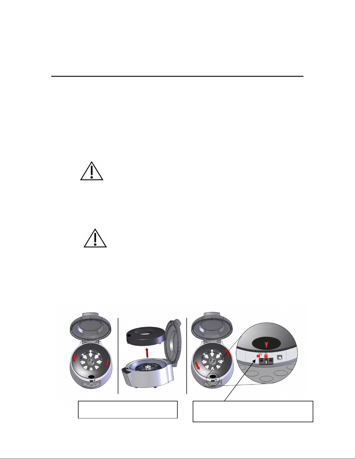
Section 3
Shield
must be locked back in original position by turning counter
-
Shield is
removable. Turn clockwise and lift to
3
33
Operating Instructions
Opening and Closing the Cover
An electronic operated cover interlock mechanism prevents operation if the cover is not completely
closed and locked, and prevents the cover from opening when the rotor is turning. An operating
cycle can be initiated only if the cover latch is engaged.
Cover Interlock By-pass
In case of power failure or malfunction, the Stop/Open button may not release the cover. To recover
samples in the rotor, the cover interlock mechanism can be released manually by inserting the
manual latch release tool supplied with the instrument into the small hole located in the front of the
housing. Push the tool inward about one inch (25 mm) to release the latch.
CAUTION - The cover interlock by-pass is for emergency use only. Misuse may
expose the operator to unsafe conditions.
Removing and Installing the Rotor
The StatSpin® Express 4 is shipped with the rotor installed and supported by a shipping retainer.
To prevent possible damage to the centrifuge’s motor mount, it is important to remove the rotor
whenever the centrifuge is moved or shipped to another location.
CAUTION- Before operating the centrifuge, ensure that the rotor is fully seated onto
the motor shaft and the hex screw is fully tightened.
To remove the rotor:
1. Open cover and remove shield. Grasp shield at the center opening and rotate clockwise.
Simply lift straight up and out of centrifuge housing.
remove.
Shield Removal & Installation
clockwise. Unit will not operate without shield in locked position.
(All 3 green cycle lights will flash if shield is unlocked)
6
Page 11

2. Locate 1/8 inch hex key supplied and remove center screw of rotor hub.
3. Remove rotor lifting straight up and out of centrifuge.
To re-install the rotor:
1. Align position 1 on the rotor with the flat on the motor shaft.
2. Slide the rotor onto the shaft and push down gently to seat. Do not force the rotor onto the
shaft. If it does not slide down easily re-align the rotor with the shaft.
3. Reinstall center screw and tighten with supplied hex key.
4. Reinstall shield into housing. Grasp shield at center and rotate counter-clockwise until in the
locked position.
Spinning the Sample
CAUTION - Never operate the StatSpin® Express 4 without the rotor and shield securely in place.
Do not attempt to by-pass any interlock switches located around bowl and shield area. Failure to
properly install and secure the rotor may result in damage to the centrifuge not covered by warranty.
CAUTION – Maintain a 300 mm (11.8 inches) clearance envelope around centrifuge during
operation. Do not deposit any potentially hazardous materials within the CLEARANCE ENVELOPE.
Loading
1. Ensure the appropriate tube inserts are installed. The StatSpin
provided with eight tube inserts for 13 x 100 mm tubes (Product No. SV09) and eight tube
inserts for 16 x 100 mm tubes (Product No. SV07). Other sizes are available (See
accessories).
2. The rotor must be properly balanced to ensure smooth operation. DO NOT spin a single tube.
3. Use the same size and style tubes in opposite positions. Balance liquid in tubes to within 0.5 mL.
4. Close and latch the centrifuge cover.
5. Select the spin time by pressing the appropriate cycle time button.
6. Press Start button.
CAUTION - Replace Tube Inserts immediately if a tube breaks during centrifugation.
CAUTION – Replace glass tubes used for rotor balancing after 10 spin cycles to reduce chances of
breakage due to the repeated stress of centrifugation.
Cycle Settings
®
Express 4 centrifuge is
The operator should select spin time settings to achieve optimum results for specific applications.
The following are general guidelines:
Setting Speed RCF
3 min Produces high quality plasma/serum from whole
blood for chemistry and cardiac testing.
5 min Produces high quality plasma/serum from whole
blood for chemistry and cardiac testing.
Recommended for most Greiner gel tubes
10 min Slower traditional spin.
Centrifugal forces are decreased to provide a ………
traditional spin.
Unloading
1. Upon completion of the cycle, the rotor decelerates to a stop, a signal beep will sound, and the
cover latch automatically releases.
2. Lift the cover and carefully remove the tubes.
5100 rpm 4000 xg
5100 rpm 4000 xg
4500 rpm 3100 xg
7
Page 12
Overview
Iris Sample Processing recommends that instrument operators perform periodic inspections and
preventative maintenance on all instruments. Contact customer service or your distributor if the
instrument is not functioning properly.
CAUTION - Unplug the StatSpin® Express 4 from the wall outlet before cleaning or performing
maintenance.
WARNING – Inspect instrument for cracks or any physical damage to housing, cover and rotor.
Damage may result in unsafe operation; discontinue use until repairs have been performed.
WARNING – Do not expose the StatSpin® Express 4 or its rotor to strong or concentrated acids,
bases or oxidizing agents, aromatic or halogenated hydrocarbons, esters or ketones.
Cleaning
The StatSpin® Express 4 is equipped with a stainless steel bowl for easy cleaning. Clean the
outside surfaces and switch overlay panel with a water-dampened cloth and mild detergent. Clean
the inner surface or bowl with a mild detergent, and if necessary, a disinfectant, wiping surfaces with
a dampened cloth using 70% alcohol or 10% bleach solution. Do not sterilize rotor.
CAUTION - Do not spray cleaning solutions directly onto the centrifuge bowl or housing;
overspray could reach the motor bearings or internal circuitry. Subsequent damage may not be
covered by warranty. Before using any cleaning or decontamination methods except those
recommended, operators should check with the manufacturer that the proposed method will not
damage the equipment.
General Cleaning
Rotor Disinfecting
Section 4
4
44
Maintenance
1. Open centrifuge cover.
2. Unplug centrifuge from the electrical outlet.
3. Remove the shield.
4. Remove the rotor (see Removing and Installing the Rotor).
5. Clean bowl area with mild detergent.
6. Re-install rotor (see Removing and Installing the Rotor).
7. Plug into electrical outlet.
1. Open centrifuge cover.
2. Unplug from the electrical outlet.
3. Remove shield to allow access to rotor.
4. Remove the rotor.
5. The rotor and inserts may be soaked in detergent and warm water or a 10% bleach solution.
6. DO NOT attempt to clean an insert that has a broken tube. Dispose of insert immediately.
7. Dry the rotor and inserts with a clean absorbent paper towel or allow to air dry.
8. Re-install the rotor (see Removing and Installing the Rotor).
9. Plug into electrical outlet.
Checking the Rotor Speed
The rated speeds (+5%) can be checked with a stroboscope or photoelectric tachometer. Point
tachometer thru transparent cover at reflective patch located near rotor center. Do not defeat any
safety interlocks while performing test. If the centrifuge fails to achieve an operating speed of 5100
rpm +5% in the 3 min and 5 min settings or 4500 rpm +5% in the 10 min setting, contact your
distributor or the Iris Sample Processing customer service department.
8
Page 13

Periodic Maintenance Check
When the cycle counter in the instrument reaches 50,000 spins, the Error/Service indicator will
continuously illuminate. This is a reminder to perform some important maintenance checks on the
instrument. Follow these steps to complete the maintenance check and reset the cycle counter:
1. Remove protective shield and rotor from the instrument (see Section 3 – Removing and
Installing the Rotor).
2. Clean the inside surfaces of the shield and bowl, as well as the rotor, with a mild detergent.
3. Inspect the cover and housing for any cracks – particularly around the hinge area.
4. Inspect the cover gasket for tears and excessive flattening.
5. Inspect the latch guide (black) on the front of the housing for cracks.
6. Inspect the keypad for cracks or worn areas.
7. Re-install the rotor and protective shield into the instrument
Damaged or cracked components found during the inspection should be replaced as soon as
possible. Replacement parts or a repair may be ordered by contacting customer service or your
distributor.
To re-set the cycle counter:
1. Hold down the 3 and 5 minute cycle buttons while powering the unit on. The instrument
will beep continuously.
2. Release the buttons. The beep will stop. The cycle counter is now reset to zero.
3. Run a test cycle to confirm that the red Error/Service indicator is not lit.
9
Page 14

Troubleshooting
Symptom: Solution:
Red Error / Service indicator flashing, unit will not spin. Refer to Error Code Table of manual to identify and correct problem.
Tubes are loose and do not fit into buckets.
No LEDs are on and unit will not spin.
Unit vibrated and shuts down.
There is a crack in the top cover or housing. Discontinue operation. Have unit serviced.
Rotor will not come off motor shaft.
Red Error LED is on and will not turn off.
Caps are popping off the tubes during centrifugation.
Centrifuge not providing platelet poor plasma.
Be sure the correct tube inserts are in use. Check insert listing
available under accessories to match with appropriate tube sizes.
Main power switch is located on rear panel along with fuse holder.
Check switch position and if necessary condition of fuses.
Confirm line cord is plugged into a powered outlet.
This instrument detected an imbalance and stopped operation. Clear
the error via keypad and check tube balance.
Remove screw and apply straight upward pressure at rotor center.
Contact Customer Service for additional information.
The cycle counter has reached 50,000 spins. Please perform the
periodic maintenance checks as indicated in Section 4.
Be sure the correct tube inserts are in use. Check insert listing
available under accessories to match with appropriate tube sizes.
Check rotor speed, and ensure tubes are balanced.
Check to make sure you are using the 5 minute setting.
Ensure probe of the analyzer is positioned vertically in plasma, no
more than ¼ inch from top surface of plasma, and away from the tube
walls.
Contact customer service for guidelines for obtaining platelet poor
plasma.
Ensure tubes are properly mixed immediately following collection.
Refer to tube manufacturer for recommended procedure.
Sample is not separating adequately.
Tubes are breaking during centrifugation.
Cover does not open.
3 min, 5 min, 10 min flashing, unit will not spin. Confirm shield is securely locked in place (counter-clockwise).
Check rotor speed and cycle times.
Allow serum tubes to clot prior to centrifugation.
Replace tube insert. Do not attempt to clean glass from inserts.
Balance tubes should be replaced after 10 cycles.
Confirm unit has power; press the Stop/Open button.
In the event of a power failure or malfunction, insert latch release tool
into the small hole on front panel. Cover will release and samples can
be removed.
10
Page 15

Service
Refer all service to Iris Sample Processing or an Authorized Repair Facility.
Instrument fuse(s) are located on the rear panel. Remove the line cord to access the fuse holder.
Replace with fuses of the same type and rating.
Be sure to complete the Warranty Registration Card as directed.
2.5A 250V F 5 x 20 mm
Decontamination before returning for service:
Any instrument or accessory that has been exposed to blood or other biological materials must be
cleaned prior to shipment to the manufacturer or distributor for service. This decontamination is
required by Federal Law (Title 48 and 49 of the Federal Regulations) and in accordance with the
Environmental Protection Agency’s Regulations for Biohazard Waste Management. Iris Sample
Processing personnel cannot perform this decontamination. Refer to maintenance section for
cleaning instructions.
11
Page 16

Specifications
Product Number
SSH4
Section 5
5
55
Appendix
Model Number
Spin Parameters
Acceleration Time
Deceleration Time
Electrical
Dimensions
Environmental
M510
3 min: 180 seconds @ 5100 rpm / 4000 xg
5 min: 300 seconds @ 5100 rpm / 4000 xg
10 min: 600 seconds @ 4500 rpm / 3100 xg
≤ 30 seconds
≤ 30 seconds
100 – 240 VAC, 50/60Hz, 2.5 Amps
Height: 8.0“ (20.3 cm)
Width: 13.0” (33.0 cm)
Depth: 16.0” (40.6 cm)
Weight: 20 lbs. (9 Kg)
For indoor use only
Ambient temperature 2ºC to 40ºC
Maximum 80% RH between 2ºC and 30ºC,
decreasing to 50% RH at 40ºC
Maximum altitude 2000 m
Specifications are subject to change without notice.
WARNING – Do not operate or store the centrifuge or its rotor below the 2oC
minimum operating temperature. At extreme low temperature (below -18oC) the rotor
material is subject to cracking under impact stress (such as dropping onto a hard
surface).
Main supply voltage fluctuations should not exceed ±10%
Transient over-voltages according to installation category II
Pollution degree 2
12
Page 17

References
A Division of IRIS International, Inc.
Westwood, MA 02090 USA
Phone: 800-782-8774
or 781-551-0100
Fax: 781-551-0036
www.proiris.com
mdi Europa GmbH
Langenhagener Str. 71
30855 Hannover-Langenhagen
Germany
+49-511-39089530
Made in USA
1. CLSI. “Protection of Laboratory Workers from Occupationally Acquired Infections;
Approved Guideline-Third Edition.” CLSI document M29-A3 [ISBN 1-56238-567-4]. CLSI,
940 West Valley Rd, Suite 1400, Wayne, Pennsylvania 19087-1898 USA, 2005.
2. CDC. Recommendations for Prevention of HIV Transmission in Health Care Settings.
MMWR (Suppl. No. 2S):2S-18S, 1987.
3. CDC. Updated: US Public Health Service Guidelines for the Management of Occupational
Exposures to HBV, HCV and HIV and Recommendations for Post Exposure Prophylaxis.
Appendix A and B. MMWR 50 (RR-11): 1-42, June 29, 2001.
55-006276-001 Rev A
13
Page 18

Iris Sample Processing Warranty
Iris Sample Processing, a Division of IRIS International, Inc. warrants that the centrifuge, with the exception of the
rotor, shall be free from defects in material and/or workmanship, under normal use and service, for the period
expiring twenty-four (24) months from the date of installation. The rotor shall be free from defects in material and/or
workmanship, under normal use and service, for the lifetime of the instrument. The purchaser must have
completed and forwarded to Iris Sample Processing the Warranty Registration Card. Iris Sample Processing will,
at its discretion, repair or replace any unit or part covered under this warranty returned to Iris Sample Processing
with shipping costs prepaid. Repaired or replaced instruments supplied under this warranty carry only the
remaining portion of the original warranty and repairs shall not interrupt or prolong this warranty. For warranty
terms and conditions outside the United States, contact your Authorized Iris Sample Processing Distributor.
No warranty extended by Iris Sample Processing shall apply to any instrument that has been damaged due to
misuse, negligence, accident, or damage resulting from unauthorized repairs, alterations, or improper installation.
Iris Sample Processing makes no warranty other than the one set forth herein. This warranty is given expressly in
lieu of all other warranties, expressed or implied. The purchaser agrees that there is no warranty of
merchantability or of fitness for any intended purpose and that there are no other remedies or warranties,
expressed or implied, which extend beyond the description on the face of the agreement. No agent or employee of
Iris Sample Processing is authorized to extend any other warranty or assume for Iris Sample Processing any
liability except as set forth above. This warranty is only applicable to the original purchaser.
Limitation of Liability
Iris Sample Processing shall not be liable for any loss of use, revenue or anticipated profits, or for any
consequential or incidental damages resulting from the sale or use of the products. The purchaser shall be
deemed liable for any and all claims, losses, or damages incurred by the use or misuse of the Iris Sample
Processing instrument by the purchaser, its employees or others, following receipt of the instrument or other items.
14
 Loading...