

Page 1

v1.02 Page: 1
IRIS8xx Series Digital Video / Hybrid Recorders
QUICK REFERENCE
GUIDE
Page 2

CAUTION! ! To reduce the risk of electric shock, the cover should only be removed when installing or
! ! ! replacing the hard drive, and this should only be undertaken by a qualified electrical
! ! ! engineer. Power must be disconnected at all times when removing the cover and working
! ! ! inside the unit.
WARNING ! ! IRIS8xx series DVRʼs are not waterproof device and therefore must not be exposed to
! ! ! rain or moisture. When installing the unit in an area that may be prone to moisture,
! ! ! always ensure the unit is housed in a suitable waterproof housing or splash shield. Care
! ! ! must be taken to ensure the rear of the unit is also not exposed to moisture or water
! ! ! ingress. Failure to observe this warning could cause fire or electric shock.
LIMITATION OF WARRANTY
!!!THIS PUBLICATION IS PROVIDED “AS IS” WITHOUT WARRANTY OF ANY KIND,
! ! ! EITHER EXPRESS OR IMPLIED, INCLUDING BUT NOT LIMITED TO, THE IMPLIED
! ! ! WARRANTIES OF MERCHANTABILITY, FITNESS FOR ANY PARTICULAR PURPOSE,
! ! ! OR NON-INFRINGEMENT OF THE THIRD PARTYʼS RIGHT.
! ! ! THIS PUBLICATION COULD INCLUDE TECHNICAL INACCURACIES OR
! ! ! TYPOGRAPHICAL ERRORS. CHANGES ARE ADDED TO THE INFORMATION
! ! ! HEREIN, AT ANY TIME, FOR THE IMPROVEMENTS OF THIS PUBLICATION AND/OR
! ! ! THE CORRESPONDING PRODUCT(S).
DISCLAIMER OF WARRANTY
!!!
!!!IN NO EVENT SHALL THE SUPPLIER BE LIABLE TO ANY PARTY OR ANY PERSON,
! ! ! EXCEPT FOR REPLACEMENT OR REASONABLE MAINTENANCE OF THE
! ! ! PRODUCT, FOR THE CASES, INCLUDING BUT NOT LIMITED TO THE FOLLOWINGS:
!!!ANY DAMAGE OR LOSS, INCLUDING BUT WITHOUT LIMITATION, DIRECT OR
! ! ! INDIRECT, SPECIAL, CONSEQUENTIAL OR EXEMPLARY, ARISING OUT OF OR
! ! ! RELATING TO THE PRODUCT;
! ! ! PERSONAL INJURY OR ANY DAMAGE CAUSED BY INAPPROPRIATE USE OR
! ! ! NEGLIGENT OPERATION OF THE USER
! ! ! UNAUTHORIZED DISASSEMBLE, REPAIR OR MODIFICATION OF THE PRODUCT BY
! ! ! THE USER;
! ! ! ANY PROBLEM, CONSEQUENTIAL INCONVENIENCE, OR LOSS OR DAMAGE, ARISING OUT
! ! ! OF THE SYSTEM COMBINED WITH THE DEVICES OF THE THIRD PARTY;
ANY CLAIM OR ACTION FOR DAMAGES, BROUGHT BY ANY PERSON OR ORGANIZATION
! ! ! BEING A PHOTOGENIC SUBJECT, DUE TO VIOLATION OF PRIVACY WITH THE RESULT OF
! ! ! THAT SURVEILLANCE-CAMERAʼS PICTURE, INCLUDING SAVED DATA, FOR SOME REASON,
! ! ! BECOMES PUBLIC OR IS USED FOR THE PURPOSE OTHER THAN SURVEILLANCE.
Warnings:
v1.02 Page: 2
NOTE: This equipment has been tested and found to comply with the limits for a Class
“A” digital device, pursuant to Part 15 of the FCC Rules. These limits are designed to
provide reasonable protection against harmful interference when the equipment is
operated in a commercial environment. This equipment generates, uses and can
radiate radio frequency energy and, if not installed and used in accordance with the
instruction manual, may cause harmful interference to radio communications. Operation
of this equipment in a residential area is likely to cause harmful interference in which
case the users will be required to correct the interference at their own expense.
FCC Caution: To assure continued compliance, use only shielded interface cables when
connecting to computer or peripheral devices. Any changes or modifications not
expressly approved by the party responsible for compliance could void the userʼs
authority to operate this equipment.
This Class A digital apparatus meets all the requirements of the Canadian Interference
Causing Equipment Regulations.
Page 3

Page Number:! Chapter:! ! ! ! Section
2! ! ! Warnings! ! ! !
!
4! ! ! Introduction! ! ! ! 1
5! ! ! Models in Range! ! ! 2
6! ! ! Drawings! ! ! ! 3
7+8! ! ! Front Panel! ! ! ! 4
9+10! ! ! Back Panel! ! ! ! 5
11! ! ! Removable Host Back Panel! ! 6
12! ! ! Connecting up your DVR! ! 7
! ! ! Power! ! ! ! ! 7.1
! ! ! Cameras! ! ! ! 7.2
13! ! ! Connecting up your DVR! ! 7
! ! ! Cameras (continued)! ! ! 7.2
!!! Video Outputs!! !!7.3
! ! ! PTZ Control! ! ! ! 7.3
14! ! ! Connecting up your DVR! ! 7
! ! ! PTZ Control (continued)! ! 7.4
! ! ! RS485 Connections! ! ! 7.4
15! ! ! Connecting to a LAN / WAN! ! 7.5
! ! ! Connecting IP Cameras!! ! 7.6
16! ! ! Remote Controller! ! ! 8
17! ! ! Operation (Part 1)! ! ! 9
! ! ! Power Up! ! ! ! 9.1
!!! Log In!!! !!9.2
18! ! ! Set Up! ! ! ! ! 10.1
19! ! ! Pre Camera Set Up! ! ! 10.1.a
20! ! ! Camera Set Up!! ! ! 10.1.b
!!!
21+22! ! ! Network Set Up!! ! ! 10.1.c
23! ! ! Mobile App Set Up! ! ! 10.1.d!
24! ! ! Password Set Up! ! ! 10.1.e
25! ! ! System Set Up! ! ! ! 10.1.f
26! ! ! RS485 Set Up (PTZʼs)! ! ! 10.1.g
27! ! ! Operation (Part2)! ! ! 11
! ! ! Viewing Cameras
28! ! ! Search Footage & Playback! ! 12
! ! ! Search by Time!! ! ! 12.1
29! ! ! Search by Event! ! ! 12.2
30! ! ! Extending Remote IR Extender! ! Appendix A
31! ! ! Mobile App Operation! ! ! Appendix B
32! ! ! Contact Information! ! ! !
Contents:
v1.02 Page: 3
Page 4

v1.02 Page: 4
Section 1:! Introduction
This manual is intended to be used as a quick reference to the main features used by marine users, with the
DVR installed and set up to operate in ʻtypicalʼ conditions - ie, using the composite video output to display
video (on a chart plotter) and controlling the device via the front panel or IR remote controller. Information on
using the FINGER CMS mobile / tablet App is also included.
For a more detailed breakdown and explanation of the products features and configuration, please refer to
the full use guide for your specific product.
Page 5

IRIS804: 4 x Composite Video Inputs
IRIS804: 4 x Composite Video Inputs
IRIS808: 8 x Composite Video Inputs
IRIS816: 16 x Composite Video Inputs
IRIS848: Hybrid Recorder - 8 Composite Video Inputs / 4 x IP Cameras
Iris may also be able to provide a solution If you have a specific requirement not covered in the above listed
range, such as HD-SDI inputs or increased IP capacity. For more details contact Iris.
NOTE:
All models above feature both a composite video output and a VGA output. However, these cannot both be
used at the same time and should be considered only as an 'either / or' feature.
v1.02 Page: 5
Section 2:! Models in Range
Page 6
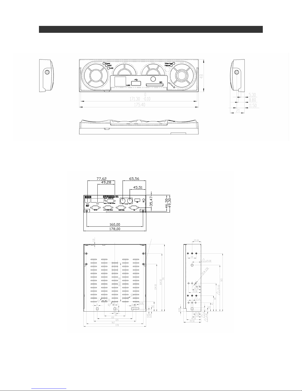
3 (a)! Front Panel
3 (b)! Back Panel & Case
v1.02 Page: 6
Section 3:! Drawings
Page 7
cc
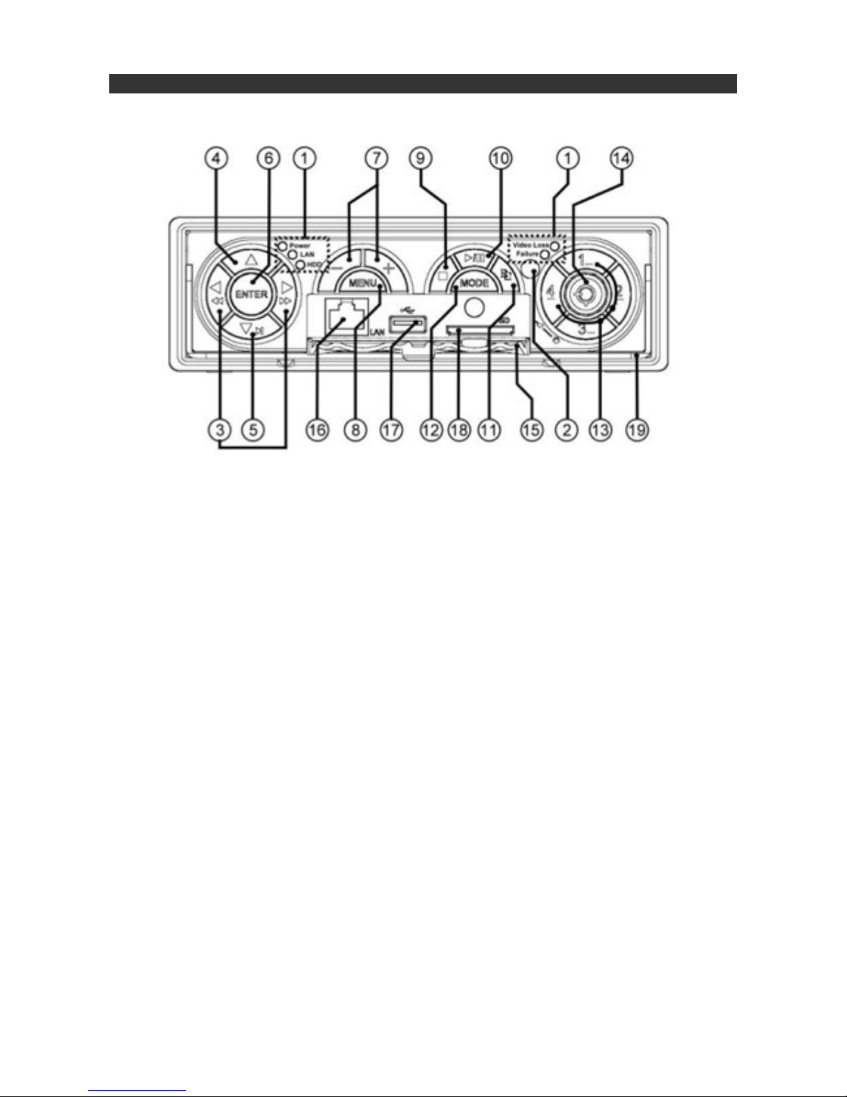
1. LED Indicators:
! Power, LAN Activity, HDD Activity (Left Side) / Video Loss, HDD Failure (Right Side)
2. IR Sensor:
! Used to receive IR commands from Hand-Held Remote Controller.
3. Left / Right Directional Buttons:
! In menu mode moves cursor LEFT / RIGHT
! When control PTZ camera, pans camera LEFT / RIGHT
! In PLAYBACK mode, press this button for FAST REWIND / FAST FORWARD
4. Up Directional Button:
! In menu mode moves cursor UP
! When control PTZ camera, tilts camera UP
5.! Down Directional Button:
! In menu mode moves cursor DOWN
! When control PTZ camera, tilts camera DOWN
! In PLAYBACK mode, press this button for SINGLE STEP
6.! ENTER Button:
! ENTER key in Menu Mode
! Also used to select control of PTZ camera. Press before sending pan / tilt / zoom etc commands.
7. + / - Buttons:
! In PTZ mode, + is used to Zoom telephoto and - is used to zoom wide.
! Also used to increase / decrease value during data entry
! In Main Screen mode, - is used to enter full screen mode, + is used to select quad / PiP
8. MENU / ESC Button:
! Displays MAIN MENU, or steps back to previous menu when further into menu chain.
! During PLAYBACK press this button for SNAPSHOT
9. STOP / PTZ Button:
! Press this button to STOP video during PLAYBACK.
v1.02 Page: 7
Section 4:! Front Panel
Page 8
! When not in PLAYBACK mode, this button selects / deselects PTZ control
10.! PLAY / PAUSE Button:
! When pressed, PLAYs or Pauses video during PLAYBACK mode.
11.! COPY Button:
! Press this button to copy selected playback images / files to your storage device (SD Card / USB
! Drive). Pressing the button a second time stops copying. This button is also used as a miscellaneous
! key in certain menus such as CALL in Playback.
12. MODE Button:
! Press this button to toggle between LIVE mode and PLAYBACK mode from the main screen display.
! Pressing the button a second time stops copying. This button is also used as a miscellaneous
! key in certain menus. This button is also used as ʻSLOW BACKWARDSʼ during playback.
13. Alpha - Numeric Buttons
! Press these buttons for camera selection thus:
! IRIS804 - Selects cameras 1~4
! IRIS808, 816, 848 - Buttons 1~4 call cameras 1~4. Camera inputs higher than 4 ʻwrap aroundʼ the 4
! buttons, for example, Camera 5 is selected by pressing button 1 twice, camera 6 is called by pressing
! button 2 twice, camera 9 is called by pressing button 1 three times consecutively and so on.
! These buttons can also be used to enter text and numbers in text entry fields.
14. Key Lock
! This locks the DVRʼs into the outer caddy. The DVR itself can be removed from the caddy and hooked
! up to a remote computer, to remove footage etc.
! The DVR must be inserted and locked into the caddy to enable power-up. If the DVR is running and
! then unlocked, the internal buzzer alarm will sound until the DVR is powered off.
15. Remote Drive Access Hatch:
! Conceals Ethernet Connector, USB connector and SD Card Slot.
16. RJ45 Ethernet Connector:
! Connects the DVR to a 10/100Base-T Network.
17. USB 2.0 Connector (USB)
! For connection of USB 2.0 compatible devices such as removable USB drive, DVD+RW drive, USB
! 3G dongle etc. Please note, maximum supply power from this port is 1.0A.
18. SD Slot:
! Insert SD card to copy stored files and images. Also used when upgrading software.
19.! DVR Handle:
! Used to pull out the DVR unit from the caddy when the key lock (14) is unlocked.
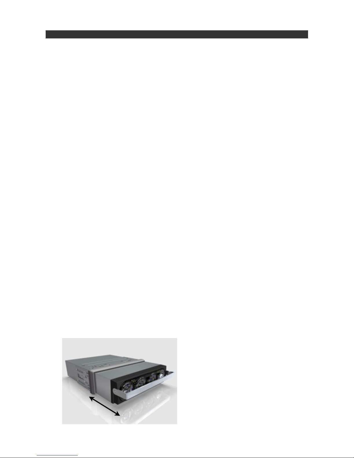
v1.02 Page: 8
Section 4:! Front Panel (Continued...)
To remove the DVR from the caddy, unlock
the key (14) and firmly pull the handle.
Page 9
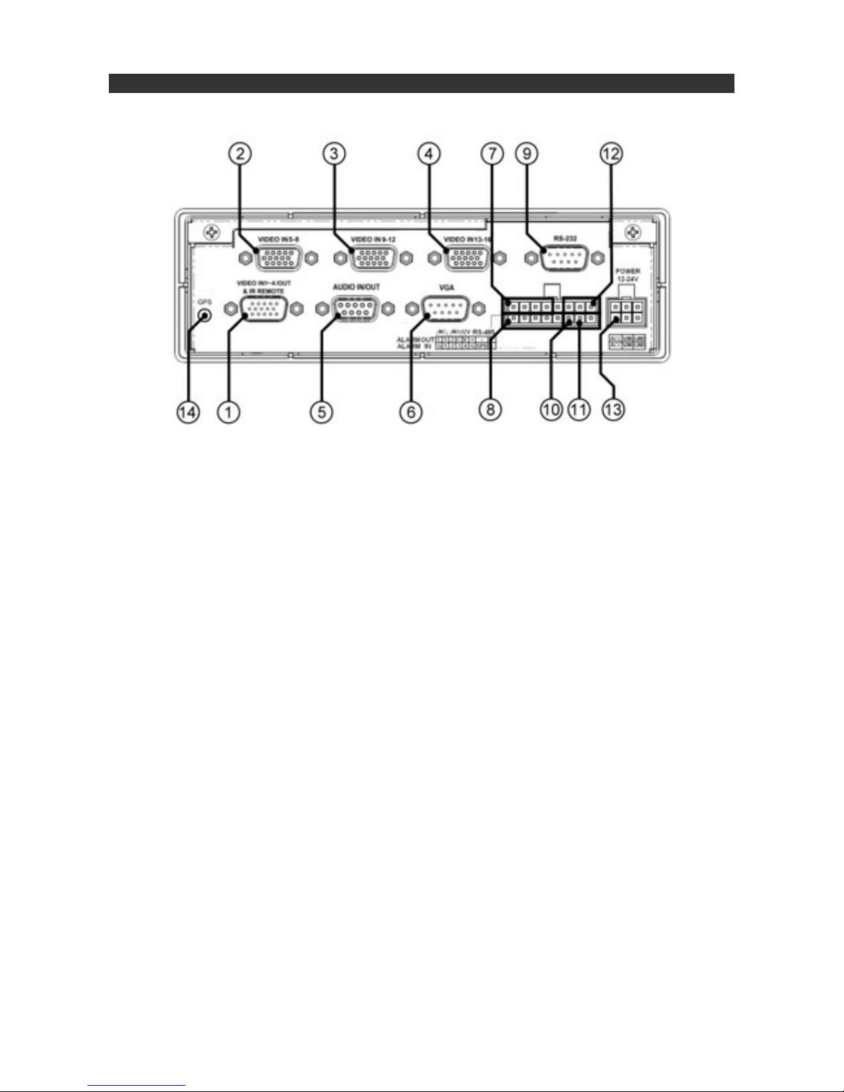
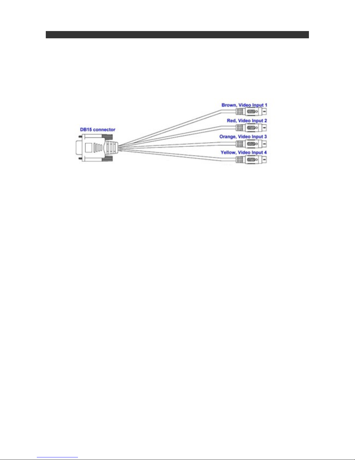
1. Video In (1-4) / Out & IR Remote Connector
! Camera Inputs 1 ~ 4, colour coded:
! Camera 1 = Brown BNC Connector
! Camera 2 = Red BNC Connector
! Camera 3 = Orange BNC Connector
! Camera 4 = Yellow BNC Connector
! Video Output = Green BNC Connector
2. Video Inputs 5-8 (IRIS808, 816, 848
! Camera Inputs 5 ~ 8, colour coded:
! Camera 5 = Brown BNC Connector
! Camera 6 = Red BNC Connector
! Camera 7 = Orange BNC Connector
! Camera 8 = Yellow BNC Connector
5. Audio In / Out Cable
! Connect Audio Input / Output Cable (Supplied)
6. VGA Monitor Output
! Connect VGA Monitor cable to the standard D-Sub 15 pin female VGA Connector.
!
! NOTE:! Although DVRʼs feature both composite and VGA outputs, they cannot both be used
! ! together. System can either user composite video output or VGA output - not both.
7. Alarm Output Connectors (ALARM OUT 1~2)
! 1 x Normally Open relay, 1 x Normally Closed relay.
8.! Alarm Input Connectors (ALARM IN 1~4)
! Connect external sensors such as PIRʼs door switches, pressure pads, beam detectors etc.
9. RS-232 Connector
! Serial Data Port for connecting RS232 devices such as PTZʼs
v1.02 Page: 9
Section 5:! Back Panel
3.! Video Inputs 9-12 (IRIS816)
! Camera Inputs 9 ~ 12, colour coded:
! Camera 9 = Brown BNC Connector
! Camera 10 = Red BNC Connector
! Camera 11 = Orange BNC Connector
! Camera 12 = Yellow BNC Connector
4.! Video Inputs 13-16 (IRIS816)
! Camera Inputs 13 ~ 16, colour coded:
! Camera 13 = Brown BNC Connector
! Camera 14 = Red BNC Connector
! Camera 15 = Orange BNC Connector
! Camera 16 = Yellow BNC Connector
Page 10

10.! Speed Input Connector
! (Not used).
11.! Engine Revolution Connector:
! (Not used).
12.! RS-485 Connections:
! RS485 A(+) and B(-) Serial Data Connections to drive compatible PTZ cameras. Colour coded:
! Black Wire = RS485 A(+)
! White Wire = RS485 B(-)
!
! Supports Pelco D protocol.
13.! Power Input
! System power. (+12 to +24VDC)
14.! GPS Antenna Connector
! Connector for plug in GPS receiver.
NOTE: IRIS804 Features a second USB connector on the rear panel.
v1.02 Page: 10
Section 5:! Back Panel (Continued...)
Page 11

1.! USB Mouse Connector
! Connect USB mouse (DVR Host Only - not extended through to outer caddy rear panel).
2.! VGA Connector
! Connect VGA Monitor (note - DVR Host does not feature composite video output)
3.! Caddy Signal Connector
! Connects to circuit board inside caddy in order to extend connections to the rear panel.
4.! Audio Output Connectors
! Connect to external line out devices (such as speakers / recorder) to hear audio in PLAYBACK
! mode.
5.! Power
! +12VDC ONLY! Although the caddy supports +12~+24VDC power, the host must only be powered
! from a +12VDC supply.
v1.02 Page: 11
Section 6:! Removable DVR Host Back Panel
Page 12

1.! Power
! IRIS8xx series DVRʼs can be run from +12 or +24VDC. Nominal load is around 500mA but the unit
! will momentarily spike at around 1.5A during boot up so this should be considered when choosing
! suitable isolation.
! The power plug connects to the back of the unit and as well as the colour coded DC+ (RED) and DC
! Ground (BLACK) wires there is a third wire (YELLOW) for connection to the ignition if required. For
! standard operation, simply common the yellow ignition wire with the red DC+ wire.
2.! Cameras
! Depending on the model, cameras are connected to the DVR via 1 or more breakout cables that
! connect to DSub15 connectors on the back of the caddy. Each connector is labelled to show the
! camera inputs and the first camera connector (only camera connector on the IRIS804) also includes
! the composite video output, IR Remote Extender jack and a screw terminal block providing DC
! output. Please note, the maximum output current supported by all DVRʼs is 2A. Using the DC output
! will naturally effect the overall current draw of the unit so please bare this in mind if you intend to use
! the DC output to power cameras for example.
v1.02 Page: 12
Section 7:! Connecting up your DVR
Red - +12 or +24 VDC
Yellow - Ignition - Tie to DC+
Black - DC Ground
The first camera connector also features the composite
video output, IR Extender socket & +12VDC outputs
Page 13
2.! Cameras (Continued...)
! Cameras 5~8 (IRIS808 / IRIS848) and cameras 9~12, 13~16 (IRIS816) are connected in the same
! way via breakout cables, each with four inputs colour coded brown, red, orange and yellow. Brown
! being the first camera in the specific input range, red the second, orange the third and yellow the
! fourth.
3.! Video Output (Monitors, Switchers, Matrices etc...)
! IRIS8xx recorders have two video outputs:
! 1)! Composite Video Output - Green BNC plug on the breakout cable for camera inputs 1~4.
! ! Outputs 1VP~P 75Ω Composite Video Signal, compatible with most chart plotters.
! ! This output can also be fed into an input on an Iris switcher (IRIS608), quad display
! ! (IRIS604) or cross point video matrix (IRIS-MAX1616).
! 2)! VGA Output - DSub15 VGA Connector on rear panel.
! ! Connects via standard VGA cable to VGA enabled monitor.
! NOTE: Although the DVRʼs feature 2 video outputs, only one can be used at any one time. For
! example, if the main composite output is used to connect to the video input of a chart plotter
! and a VGA monitor is subsequently connected, the composite output will be lost.
4.! PTZ Control Via RS485 Serial Data Connection
! Each camera input can be configured in the setup menu as a PTZ (Pan / Tilt / Zoom) device, and
! protocols and camera address IDʼs set. For more information, refer to section X.XX.
!
! For Single PTZ Cameras:!
! To connect the control data to a single camera, simply join the black and white wires of the
! rectangular 16 way multipole connector to the appropriate control wire from your camera, taking care
! to observe the correct polarity.
! NOTE: If the polarity of the RS485 camera is incorrect, the camera will not respond to
! telemetry control commands. Donʼt panic - your camera will not be damaged in this
! circumstance. Simply reverse the polarity to fix the problem.
v1.02 Page: 13
Section 7:! Connecting up your DVR (Continued...)
Camera 5, 9 or 13
Camera 6, 10 or 14
Camera 7, 11 or 15
Camera 8, 12 or 16
Page 14

4.! PTZ Control Via RS485 Serial Data Connection (Continued...)
!
! For Multiple PTZ Cameras or Controllers:
! As IRIS8xx DVRʼs can be used to transmit PTZ control data, they are regarded as a controller (in the
! same way as our IRIS516 or IRIS595 joystick controllers).
! For systems that have more than one controllable (PTZ) camera, and/or multiple controllers, such as
! a DVR and a joystick controller, the serial data has to be managed to ensure there are no issues with
! the serial data levels. noise and interference etc. This is achieved by routing the serial data through
! one of Irisʼs Serial Data Distributors (known as data expanders). The diagram below shows a typical
! system that uses both a DVR and a joystick controller to control one or more PTZ devices:
!
! RS-485 Connections:
!
!
!
v1.02 Page: 14
Section 7:! Connecting up your DVR (Continued...)
IRIS8xx DVR
IRIS516 Joystick
IRIS-EXP0204
Serial Data Distributor
IRIS116 PTZ Camera
IRIS116 PTZ Camera
RS485 A (+) Black RS485 B (-) White
Page 15

5.! Connecting to an LAN / WAN
!
!
! IRIS8xx series DVRʼs feature in-build video server capabilities meaning the device can be figured on
! an ethernet network and accessed via a PC / MAC / Smartphone and / or Tablet. When connected to
! a WiFi Router, you can view and control cameras wirelessly, on an iPad for example, and by
! connecting your router to a 4g modem, satellite internet hub or marina WiFi service you can view
! and control connected cameras remotely across a WAN connection.
! The 10/100BaseT RG45 Ethernet connector is concealed beneath the flap on the front of the unit.
! Network setup is covered in section 10.1.c.
6.! Connecting IP Cameras (IRIS848 Only)
! The IRIS848 Hybrid Recorder supports both analogue and IP cameras. To connect IP cameras
! (maximum 4 cameras), hook the DVR up to your network router and then connect your cameras to
! your network ensuring addressing is within the same range.
! Camera configuration is covered in section 10.1.c. !
v1.02 Page: 15
Section 7:! Connecting up your DVR (Continued...)
Page 16
IP/0920/071/18
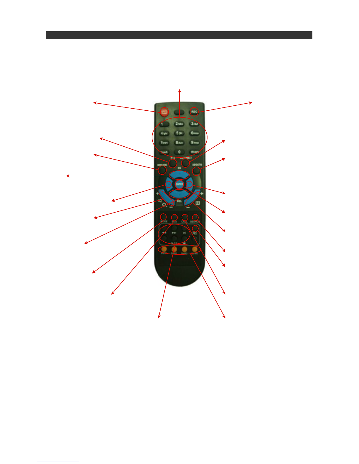
The Remote Control is an alternative method of controller the DVR and also augments front panel operation.
With a range of around 10 meters, the effective distance can be increased be using suitable IR extenders.
Refer to Appendix X. Operates on 2 x AAA batteries (supplied).
v1.02 Page: 16
Section 8:! Remote Controller
Alarm Reset
Cancels Active Alarms
RECORD
Activates manual recording
Alpha Numeric Keys (1~9, 0, *, #)
Used for camera selection. Also
used to enter text and numbers
(similar to mobile phone operation)
in various configuration functions,
such as setting IP address.
MENU / ESC
Enter / Exit Menu Mode
PTZ
Press this button to enter PTZ
control mode (assuming the current
camera is a PTZ camera)
MUTE / NEXT
Mutes any audio. In PTZ mode steps to
the NEXT control.
X2 / GOTO
In full screen display, press once for x2
digital zoom and twice for x4 digital
zoom. In PTZ mode, press this button
then the desired number to call presets
UP / BS
In menu mode, moves cursor up and also
acts as a back-space key in character
entry. In PTZ mode, tilts camera UP.
ENTER
Enters Menu Mode and confirms
selections, text entry etc.
RIGHT KEY
Pans PTZ cameras RIGHT and moves
cursor right in MENU operationLEFT KEY
Pans PTZ cameras LEFT and moves
cursor left in MENU operation
VOLUME / ZOOM
Adjusts volume in PLAYBACK mode
Controls ZOOM in PTZ mode
SPLIT-SCREEN / FOCUS
Steps through split screen modes.
Controls FOCUS in PTZ mode
DOWN / DEL
Moves cursor down. In PTZ mode tilts
camera down. In text editing mode,
works as a delete key.
SEARCH
Displays SEARCH menu
COPY
Copy selected files to storage device
(SD Card / USB)
CALL
Switch to or return from Full Screen
Display of the selected camera
DVR Select
Selects up to 4 connected DVRʼs
Transit Controls
Play, Search, Rewind, FFwd, Pause,
Stop in PLAYBACK mode.
MODE
Toggles between live screen and
playback mode in main screen.
SEQ
Switch or return from SEQ display
mode in main screen.
Page 17

1.! Power Up
! Once you have connected the DVR power, the DVR will boot up. This will take several minutes as
! the DVR software loads and the system initializes. During the boot-up procedure, the screen will
! initially turn black. Current consumption averages at around 500mA, but during this phase it will
! spike to around 1.5A for a second or two as the HDD drives are initialized.
! Front panel LEd indicators will show Power status and HDD activity.!
! After a short while, you !will notice am arrow style cursor on the screen. Shortly after this the screen
! should change colour to a vibrant blue, and then the quad image frame will appear on the
! screen. A few seconds later, any connected cameras will be displayed.*
! * IP Cameras will not be shown until configured in the camera setup menu.
2.! Log In
! Once the DVR has powered up you must log into the system in order to select cameras, change the
! view, review playback and enter the configuration menus.
! a)! Press the MENU button on the front panel. You will be presented with the following icon
!!panel:
! b)! Ensure the LOG IN tile is selected and then press ENTER. The following panel will display:
! ! Use the UP and DOWN arrows to select the desired field and then enter your user name and
! ! password accordingly. When finished, move to the Login button and press ENTER.
!!NOTE: Default login name is ʻaaʼ and the default password is 11. If you wish to retain these
! ! settings, simply highlight the ʻLoginʼ button and press enter. Most people choose to retain
! ! these login credentials, however, if you would like to change them, refer to section X.XX.
! ! Once logged in, you will be presented with the MENU panel shown above. To exit back to
! ! the main operation mode from this point, simply press the MENU key. Alternatively, use the
! ! arrow keys to navigate to your desired option and use the ENTER key to select your choice.
v1.02 Page: 17
Section 9:! Operation (Part 1 - Power Up & Log In...)
Log In Status
Volume
Video
Adjust
Display
Backup
Device
Software
Upgrade
Shutdown
Exit Menu
Setup
Page 18

1.! Setup
! Once logged in you will need to set up your system. For example, the DVR needs to know which
! cameras are PTZ and if so what address they are set to, or if an input is an IP camera, if so, what
! resolution (IRIS848 only).
! In this guide we will discuss basic setup options as listed below:
!!a)! Pre Camera Set-Up
!!!Camera input type, PTZ / IP settings, Resolution
!!b)! Camera Set-Up
!!!Camera title, video/motion alarms, image mirror*, sequence dwell time, audio and
! ! ! the various refresh rate options.
! ! ! *For rear facing cameras (back up cameras) it is usual to ʻMirrorʼ the image, so what
! ! ! you see on the chart-plotter screen accurately represents the correct image
! ! ! orientation. A ʻstandard viewʼ camera image when pointing directly backwards will
! ! ! appear reversed when displayed on the screen.
!!!Note: This guide will only cover the most common features. For full
! ! ! description of all features refer to the full operation manual for your product.
! ! c)! Network Set-Up
!!!Configure your DVR onto your network, set address, DHCP settings etc, DDNS
! ! ! settings and information.
!!d)! Mobile App
!!!Download FINGER CMS remote viewer for smart phone or tablet.
!!e)! Change Password
!!!Change user name and password settings if desired.
!!f)! System Set-Up
!!!Time & Date, Time-zones, Language etc
!!g)! Serial Data Setup (RS485) for PTZ Cameras
!!!Define serial protocol and protocol settings.
!
! ! ! From the main icon panel, navigate to the SETUP tile, and press enter to select. You
! ! ! will be presented with the main ʻSetup (Administrator) sub-menu shown below:
v1.02 Page: 18
Section 10: Setup
Pre Camera
Setup
Camera
Setup
Alarm
Setup
Main / SEQ
Display
Scheduled
Record
Previous
Menu
Factory
Settings
HDD
Settings
Password
Setup
System
Setup
RS232 / 485
Setup
Network
Setup
Vehicle
Settings
NOTE:
Greyed Out options are not
discussed in this guide. Refer
to full product guide for further
information.
Page 19

1.a! Pre-Camera Setup
! In Pre-Camera Setup, you define camera type, address (PTZ ID or IP Address) and resolution. You
! can also adjust the recording compression setting from Normal to High.
! Navigate to the Pre Camera icon from the Set-Up sub-menu and press ENTER. The following panel
! will be displayed. Use the arrow keys to navigate around the panel. Each field will either require an
! ON/OFF selection, performed by simply toggling the ENTER key, or as shown in the screen grab
!below, a ʻ- +ʼ appears indicating an adjustable value.
!
!
!
! Use the + or - key accordingly to step up or down until you arrive at the desired value, then navigate
! away from the field with the arrow keys to the next parameter, of press MENU to step up to the
! previous menu. If you have changed any of the values, you will be presented with a dialogue box
! asking if you would like to save the configuration changes. Press ENTER to save and exit back out
! to the previous menu, or MENU to exit without saving your changes.
! IP Camera Settings
! To configure IP cameras (IRIS848 only), navigate to the camera TYPE field for the specific input you
! wish to configure (for example, if you have an IP camera you wish to display and record as camera
! 4, navigate to the TYPE field for Camera 4) then press + / - until the camera type changes to IP Cam
! X (where X is the number of the IP camera you are configuring (ie, if this is the first IP camera you
! are configuring, toggle until the value changes to IP Cam1; if itʼs the second IP camera you are
! configuring, toggle until the entry changes to IP Cam2 and so on)).
! Now navigate to the IPCAM Settings field appropriate to the camera you are configuring and press
! ENTER. This will take you to the IP Camera setup page.
! The DVR firmware supports a range of ONVIF certified cameras. An automatic DISCOVER function
! is provided so you may be able to configure automatically if the particular camera is supported. All
! IRIS IP cameras, except the IRIS710 are currently supported. Navigate down to the DISCOVER
! button and press. If the camera is supported it should appear in the IPCam list below. If your camera
! requires a user name and password, these can be entered in the fields above using the numberic
! keys on your remote control.
! If your camera is not listed within the current firmware, you can set the MODEL type to RTSP and
! manually enter the cameras IP address in the URL field below for both the main and secondary
! streams.
! Once you have configured your cameras, press the MENU button to step out of the current page. To
! exit the menu completely, press MENU until you are returned to the main menu. You will be
! presented with a dialogue box asking if you want to save your configuration changes. Press ENTER
! to save, or press MENU to discard your changes.
!
v1.02 Page: 19
Section 10: Setup
Page 20

1.b! Camera Setup
! In the camera setup screen you can change the camera title, define recording quality and frame rate
! for various conditions (such as normal recording, alarm recording etc) and mirror the image (ie, for
! reversing cameras). The other settings shown in the menu arenʼt frequently used so we wonʼt cover
! them in this document - refer to the main user guide for further information.
!!Camera Title
!!Use the arrow keys to navigate to the camera title field. By default this is set the camera
! ! input number. Press the ENTER key to edit the highlighted field. A flashing cursor will
! ! appear. You can now use the number keys on the remote controller to input text in a similar
! ! way to entering text from a phone keypad - for example, Press button 1 once for the numeral
! ! 1, twice for the letter A, three times for the letter B etc. The keys on the controller are labelled
! ! accordingly to show what characters are available on each button. If you need to move the
! ! cursor forward or backwards through the highlighted text field, use the LEFT or RIGHT arrow
! ! buttons.
! ! If you make a mistake, press the BS key to remove the character to the left of the cursor, or
! ! use the DEL key to delete the currently selected character.
!!Video Loss Settings:! Refer to main user guide
!!
! ! Motion Detection: ! Refer to main user guide
!!Motion Mask:! ! Refer to main user guide
!!Covert:!! ! Refer to main user guide
!!
!!Mirror
!!Press the + / - keys on either the controller or the front panel to toggle through the following
! ! options:
! ! Horizontal Flip: For inverting image on rear facing cameras (standard orientation)
! ! Vertical Flip: For inverting the image on forward facing cameras mounted in the hanging
! ! orientation
! ! Horizontal+Vertical Flip: For inverting image on rear facing hanging cameras.
!!!
v1.02 Page: 20
Section 10: Setup
Page 21

!!
!!Call By Event:! ! Refer to main user guide
!!Dwell Time:! ! Refer to main user guide
!!Audio:! ! ! Refer to main user guide
!!Record Quality
!!Use the arrow keys to navigate to this option so it is highlighted, then use the + / - keys to
! ! increase or decrease record quality as desired. 1 is the lowest (rough) quality and 9 is the
! ! highest (fine).
!!Event Record IPS (Images Per Second).
!!Sets the recording frame rate for any event recording, such as motion detection, alarm
! ! recording etc. This value will also be the same for any Post Recording that is configured.
! ! Use the + / - keys to adjust value as desired.
!!Pre Record IPS (Images Per Second).
!!Defines the frame rate for the pre-record period for any event such as alarm recording,
! ! motion detection etc. Use the + / - keys to adjust value as desired.
!!Normal Record IPS (Images Per Second).
!!Sets the normal recording frame rate (ie, the rate at which the DVR records with no alarm or
! ! event activity). Please note, the higher this is set to, the more storage on your hard drive is
! ! required. Please refer to the storage table in section X.XX
1.c! Network Setup
! This is where you configure your network settings to allow control of the DVR, view video and control
! PTZ cameras across an ethernet Network. By setting up your DVR on a LAN or WAN you can for
! example, control PTZ cameras from an iPad running the FingerCMS APP on board or if connected to
! a cellular router or Satellite internet connection for example, view and control remotely over a WAN
! connection.
!!Net Type
!!Use the + / - keys to toggle between DHCP (if you want your router to assign an IP address)
! ! and Static IP Address if you want to set your own fixed address. PPPoe (Point to Point
! ! Protocol over Ethernet is also available although not usually used.
v1.02 Page: 21
Section 10: Setup
Page 22

!!Static IP
!!If Static IP is selected in the Net Type field, use the numeric keys on your controller to enter
! ! the static IP address details, Subnet Mask, Gateway and any DNS details as required.
! ! This must be in your network range. If necessary, contact your network provider or IT
! ! manager with any address queries.
!!PPPoE
!!Not regularly used. Refer to main user guide.
!!P2P
!!Not regularly used. Refer to main user guide.
!!DDNS
!!If you are using a DDNS service, use this section to set up the following:
!
!!!Type:! Use + / - keys to toggle Dynamic, Static, Custom DDNS.
!!!
!!!URL:! Use the remote controller to enter your DDNS URL
!
!!!Username & Password:! Use the remote controller to enter Username and
! ! ! ! ! ! ! Password Details accordingly.
!!NOTE: Please contact your local DDNS Service Provider for full details.
! ! Notification
!!Not regularly used. Refer to main user guide.
!!NOTE: Port Forwarding
!!By default, the DVR uses ports 67 for control and 68 for data. Please ensure these two ports
! ! are forwarded on your router otherwise you will not be able to gain remote access. If you are
! ! unfamiliar with configuring routers etc then contact your IT agent.
v1.02 Page: 22
Section 10: Setup
Page 23
1.d! Mobile App
! IRIS8xx series DVRʼs are compatible with a popular App available for both iOS and Android
! devices called FingerCMS. This is available to download free from the Apple AppStore and
! the Google Play Store.
!!
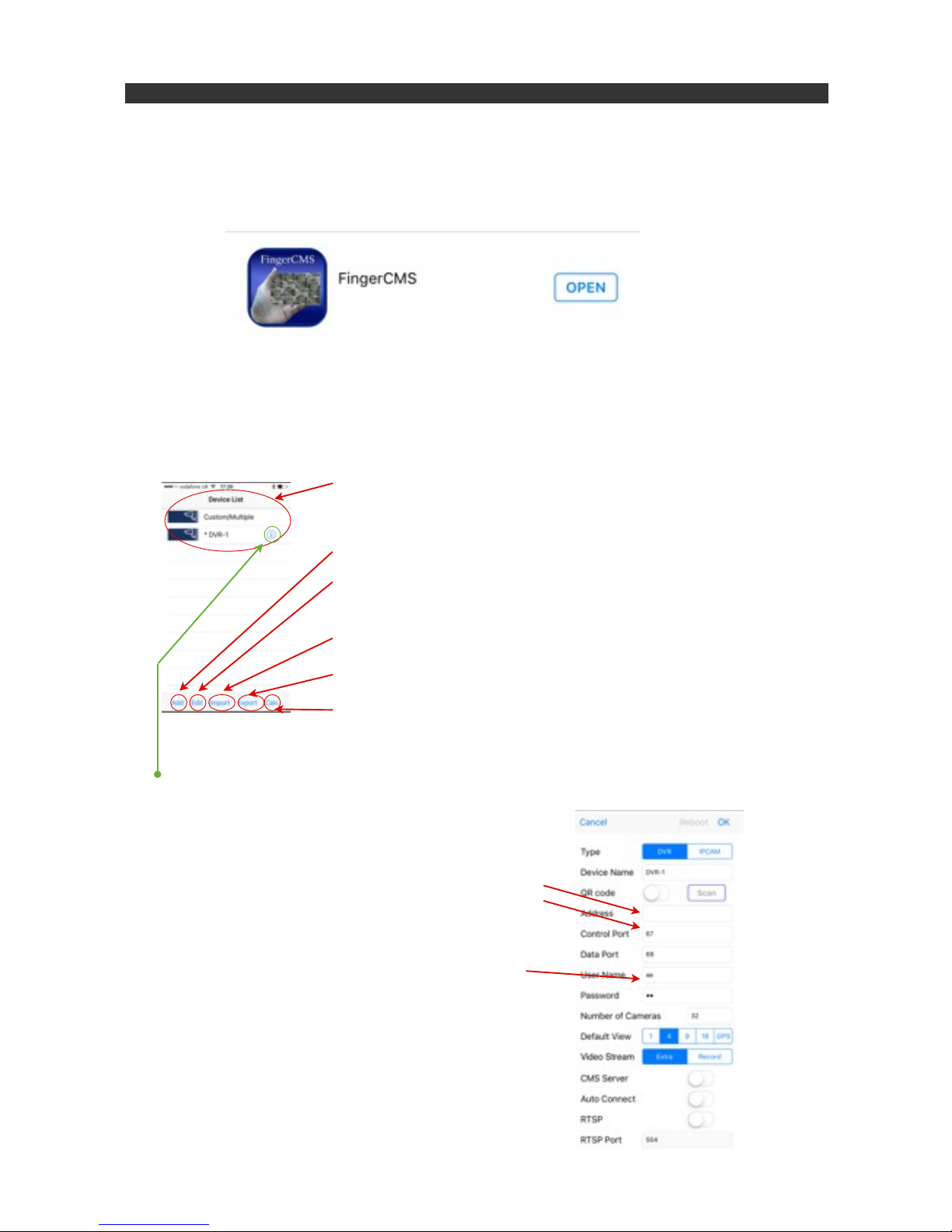
! Once downloaded and installed onto your device, launch the App.
! After the boot-up screen, you will be presented with the Device List. This is where you select
! the DVR you wish to connect to. FingerCMS lets you configure multiple devices.
! ! ! ! Device List - Shows configured DVRʼs - Select the appropriate DVR to
! ! ! ! access the user interface and view video / control PTZ cameras etc...
!!!!
! ! ! ! Add Button - Touch this to add a new device
! ! ! ! Edit Button - Touch this to edit list (Note: This does not edit the DVR settings,
! ! ! ! only items in the device list).
! ! ! ! Import - Imports video files.
! ! ! ! Export - Exports video files.
! ! ! ! Calc - A very handy calculator tool for working out available storage space
! ! ! ! on your hard drive, taking into consideration compression and record quality
! ! ! ! settings.
! Note: - If you want to go back into the configuration for a specific device after its been set up,
! highlight the DVR on the list and then touch the ʻiʼ button.
! Configure your DVR
! Click the ʻAddʼ button to add a new device to the list.
! This brings up the configuration page (right).
! From here, give the DVR a name and set itʼs IP address.
! You notice (as mentioned previously) that the control ports
! and data ports are set to 67 and 68 respectively. If these
! have been changed on your router then make sure the
! changes are reflected here, otherwise leave these as
! default. The same goes for the device user name and
! password, which by defeult are set to aa and 11 respectively.
! There are additional settings to define the number of cameras
! the interface will display (set this to the number of cameras
! supported by your DVR otherwise youʼll get lots of blank
! screens (or not enough screens if you set it lower!).
! We recommend the other settings are left as they are. For
! more details download the user guide for FingerCMS.
v1.02 Page: 23
Section 10: Setup
Page 24

1.e! Password Setup
! Change password and set access levels from within this menu. In most cases this is left to default,
! but if you wish to change Log in names and passwords and set up multiple users itʼs done from here.
! Local Guest Level
! Use the + / - keys to determine functionality available to a user who has not logged in, local to the
! device (ie, from the front panel or remote control).
! (Administrator. Supervisor. Operator.)
! Remote Guest Level
! Use the + / - keys to determine functionality available to a user who has not logged in, from a remote
! connection (ie, from a PC across a LAN or WAN connection).
! (Administrator. Supervisor. Operator.)
! Auto Logout
! Use the + / - keys to define a time period of inactivity after which the DVR will automatically log out.
! (From 1 minute to 24 hours).
! Login Name
! Use the text entry buttons on the remote controller to define a login name (user name).
! Reminder: - use the number keys on the remote controller to input text in a similar way to entering
! text from a phone keypad - for example, Press button 1 once for the numeral 1, twice for the letter A,
! three times for the letter B etc. The keys on the controller are labelled accordingly to show what
! characters are available on each button. If you need to move the cursor forward or backwards
! through the highlighted text field, use the LEFT or RIGHT arrow buttons.
! If you make a mistake, press the BS key to remove the character to the left of the cursor, or use the
! DEL key to delete the currently selected character.
! Password
! Use the text entry buttons on the remote controller to define a password specific to the user name.
! Level
! Use the + / - keys to toggle level of functionality available to each user. User levels are:
! Administrator, Supervisor, Operator or Customized. Feature access for customized user level is set
! by navigating to the ʻAdvʼ button for each specific user and pressing the ENTER key to display the
! User Setup window. For more information on setting up customized user levels refer to the
! main user manual.
v1.02 Page: 24
Section 10: Setup
Page 25

1.f! System Set Up
! The system set up page allows you to define the time zone the DVR will operate in, set daylight
! saving settings, language settings and make any changes to the system time source. The device
! protection key is also displayed on this page. This is only required for connecting remote software.
! Time Zone
! Use the + / - buttons to choose your appropriate time zone from a drop down list that will appear.
! Daylight Saving Time
! Use the + / - buttons to choose the appropriate change to the time during daylight saving periods
! from the drop down list.
! System Time
! Use the + / - buttons to toggle synchronization OFF (internal sync) or ON (sync with server defined in
! the TSP Server field). For further details refer to the main menu.
! Display Format
! Use the + / - buttons to toggle the format time information is shown on the screen.
! Language
! Use the + / - buttons to select the system language (default = English).
! Protection
! Refer to main user guide.
v1.02 Page: 25
Section 10: Setup
Page 26

1.g! Controlling PTZ Cameras (RS485 Setup)
! If you have PTZ (Pan, Tilt, Zoom) cameras connected to the DVR they can be controlled locally from
! the front panel and/or remote controller and also remotely over a LAN/WAN connection via a remote
! PC or smartphone / tablet running the FingerCMS App.
! Before you can drive the camera you will have to set up the serial data settings and also define the
! protocol used to communicate with the camera, and define the cameras unique physical address.
! Camera Address
! Each controllable camera must have its own unique address, otherwise when you send control
! commands from the DVR to the camera (such as pan left, tilt up, zoom in etc) cameras that share an
! address will move together. After you have set your cameras addresses as desired, go into the Pre
! Camera set up menu (refer to section 10.1.a) and set the address in the appropriate PTZ ID field.
! Usually, to avoid confusion, the camera connected to input 1 will be addressed 1, the camera
! connected to input 2 will be addressed 2 and so on...!
! Connecting Data Wires
! IRIS8xx series DVRʼs communicate to PTZ cameras via a two wire RS485 serial data connection.
! Refer to section 7.4 for details on the DVRʼs RS485 connections, as well as your cameras user
! guide. For quick reference, use the black (RS485 A(+)) and white RS485 B(-)) wires on the 16 way
! rectangular connector on the rear of the DVR.
!
! RS232/485/GPS Setup
! Once your cameras have been set up and you data wires connected up either directly from the DVR
! to the camera or via a serial data distributor (see section 7.4), the final step is to configure the serial
! port on the DVR.
!
v1.02 Page: 26
Section 10: Setup
Page 27

The default screen format shows a four camera quad screen view. Depending on the model of DVR you
have you can cycle through various multi-screen displays as described below. In the case of the IRIS804 that
has a four camera input, the viewing options are limited to quad screen and individual full screen displays for
each camera, selected by pressing the number buttons as required (refer to section 4.13). To change from
full screen view back to quad view, select the - button (refer to section 4.7). Pressing the + key steps through
the various multi screen views. Viewing options are relevant to the model DVR you have. Pressing the - key
steps back through the views.
To select a full screen camera input, press the appropriate number key on the remote controller, or use the
four number keys on the front face of the DVR (refer to section 4.13).
When in full screen mode, pressing the - key will switch to the last selected multi screen view.
v1.02 Page: 27
Section 11: Operation Part 2 - Viewing Cameras
CAM:1 CAM:2
CAM:3 CAM:4
CAM:5 CAM:6
CAM:7 CAM:8
CAM:9 CAM:10
CAM:11 CAM:12
CAM:13 CAM:14
CAM:15 CAM:16
Main Screen View Press + (IRIS808 / 816 / 848) Press + (IRIS816 only)
Press + (IRIS816 only)
CAM:1 CAM:2
CAM:3
4 5
76
Press + (IRIS808 / 816 / 848)
1 2 3
4 5 6
7 8
Blank
Press + (All models)
Press + (IRIS816 only)
1 2 3 4
5 6 7 8
9 10 11 12
13 14 15 16
Page 28

There are five ways to search your recordings but the following two are recommended (refer to main manual
for full descriptions).
1)! Search by time
2)! Search by event
To access the search menu, press the SEARCH button on the remote controller (ref Section.8) or press the
SEARCH button on the front panel (ref Section 4.11). The following panel will be presented - Use the arrow
keys to select your desired search method then ENTER to select:
1.! Search by Time
! The panel on the right shows the Search by Time Menu.
! To search by time, simply input your desired time and date
! using the arrow keys to navigate and + / - to set as desired.
!
! Then, in the Video / Audio section, toggle the type of events
! you wish to view (Normal recording, video loss, motion,
! alarm).
!
! Once you have set the system as required, either press
! PLAY to start playback of all camera inputs from the set time
! or COPY to backup from the configured time to the
! configured back up device (refer to main guide).
v1.02 Page: 28
Section 12: Search Footage & Playback
Search by Time Search by Event Smart Search
Archive Search POS Search Exit
Page 29

2.! Search by Event
! The panel on the right shows the search by
! Event menu. There are four types of event log:
a) Alarm
b) Motion
c) Video Loss
d) System
! Select the desired event type, then use the
! directional keys to move down to the Source ID
! panel and select the specific camera inputs you
! wish to include in the search. There are other
! options you can bring into the search but these
! are not usually used for marine applications -
! refer to main manual if you wish to learn more
!
! about these options.
! Once you have set your search criteria, press the MODE button (refer Section 4.12 for front panel
! operation) and the Event Log will refresh. The Event Log may take up many pages. In this case use
! the SEQ (front panel: refer section X.XX) and CALL (front panel: refer section 4.11) buttons to page
! UP / down accordingly.
! Use the directional keys to select the desired event log entry then PLAY to start playback, COPY to
! backup the event log file to the configured backup device or SEARCH to export the event log itself to
! the backup device.
v1.02 Page: 29
Section 12: Search Footage & Playback (Continued...)
Page 30

The remote controller that is supplied with your DVR works to arrange of around 10 meters when aimed
directly at the units front panel. In situations where a greater range is required, or where the DVR is to be
hidden, an IR Extender can be used.
The IR Extender plugs into the blue 3.5mm stereo jack socket found on the cable tail that also features Cam
Inputs 1~4 as shown in the picture below.
The drawing below illustrates the connector wiring is required:
Any IR Extender that uses the same pin out configuration can be used.
Appendix A: Adding an IR Extender for the Remote Controller
Cam 1~4, 12VDC Output + IR Extender (Blue Jack)
2.5mm Diameter Male Stereo
View other Marine Electronics & Navigation made by IRIS Products on our website.
 Loading...