

Page 1
1. Introduction
Operators Manual
Page 2
1. Introduction
Click to select
English Deutsch
Français Italiano
Español Português
Page 3

Table of Contents
Table of Contents
Chapter 1 - Introduction
Introduction .......................................................................................................................7
Intended Use ................................................................................................................. 7
How to use the Operator’s Manual.................................................................................... 7
Precautions and Warnings ................................................................................................8
Notes ............................................................................................................................. 8
Cautions ........................................................................................................................8
Warnings .......................................................................................................................8
Biological Warnings....................................................................................................... 8
Warnings, Precautions, Limitations................................................................................... 8
Iris Diagnostics Contact Information .................................................................................9
Warranty............................................................................................................................ 9
Limitation of Liability........................................................................................................ 10
Chapter 2 - System Description
Theory of Operation ........................................................................................................ 12
Features ......................................................................................................................12
Test Strips ...................................................................................................................12
Optics ..........................................................................................................................13
LED Unit................................................................................................................... 13
CMOS Image Sensor............................................................................................... 14
Optics Calibration..................................................................................................... 14
Measurement ........................................................................................................... 14
Instrument Components.................................................................................................. 15
Front ............................................................................................................................ 15
Back............................................................................................................................. 15
Software.......................................................................................................................... 17
Data Entry Fields ......................................................................................................... 17
Toggle Fields............................................................................................................... 17
Function Keys .......................................................................................................... 18
Menu Diagram ............................................................................................................. 18
Main Menu ............................................................................................................... 18
Worklist Menu .......................................................................................................... 18
Run Patient Menu .................................................................................................... 19
Results Menu........................................................................................................... 19
Controls Menu.......................................................................................................... 19
Setup Menu.............................................................................................................. 20
Microscopic Menu .................................................................................................... 20
Service Menu ........................................................................................................... 20
300-4410 English Rev C 01/2007 Operators Manual 2
Page 4

Table of Contents
Specifications.................................................................................................................. 21
Consumables or Part Replacement ................................................................................ 22
Chapter 3 - Set Up
Setting the Language...................................................................................................... 24
Setting Date and Time .................................................................................................... 25
Setting the Date or Time Format ................................................................................. 26
Changing the Date and Time....................................................................................... 26
Setting the Reporting Units ............................................................................................. 28
Conventional (mg/dL) Units ......................................................................................... 29
Standard International (µmol/ L) units ......................................................................... 29
Qualitative (+) units ..................................................................................................... 29
Customized Units ........................................................................................................ 30
Printing Units ............................................................................................................... 30
Sample Print Layout................................................................................................. 31
Setting the Flagging Criteria............................................................................................ 32
Microscopic ..................................................................................................................... 34
Print a Copy of Microscopic Setup ..............................................................................36
Setting the Test Sequence.............................................................................................. 37
Setting the Log On Identifiers.......................................................................................... 39
Adding a New User...................................................................................................... 40
Editing a User Information ........................................................................................... 41
Deleting a User............................................................................................................ 43
Setting Up the Printer...................................................................................................... 45
Setting Transmitting Results ........................................................................................... 47
Chapter 4 - Specimen Processing
Powering the Instrument On ........................................................................................... 49
Logging On .................................................................................................................. 49
Logging Off.................................................................................................................. 50
Running Single Specimen Analysis ................................................................................ 51
Entering Patient Information ........................................................................................ 51
Sequence Number ................................................................................................... 51
Specimen/Patient ID ................................................................................................ 51
Last Name................................................................................................................ 51
First Name ............................................................................................................... 52
Clarity....................................................................................................................... 52
Specimen Type ........................................................................................................ 53
Analyzing the Urine .....................................................................................................54
Running Batch Specimen Analysis ................................................................................. 57
Creating a Worklist ...................................................................................................... 57
Sequence Number ................................................................................................... 59
Specimen/Patient ID ................................................................................................ 59
300-4410 English Rev C 01/2007 Operators Manual 3
Page 5

Table of Contents
Last Name................................................................................................................ 59
First Name ............................................................................................................... 59
Clarity....................................................................................................................... 59
Specimen Type ........................................................................................................ 60
Downloading a Worklist............................................................................................... 62
Viewing and Editing a Worklist .................................................................................... 63
Running a Worklist ......................................................................................................65
Printing a Worklist........................................................................................................ 67
Running a Stat ................................................................................................................68
Chapter 5 - Controls
Setting the Control Run Frequency.................................................................................72
Setting a Control File....................................................................................................... 73
Creating a Control File................................................................................................. 73
Editing Control File Information ................................................................................... 75
Deleting Control File Information ................................................................................. 76
Running Controls ............................................................................................................77
To accept the results ...................................................................................................78
To reject the results ..................................................................................................... 78
Control Results................................................................................................................ 79
Viewing Control Results ..............................................................................................79
Printing Control Results...............................................................................................80
Deleting Control Results..............................................................................................80
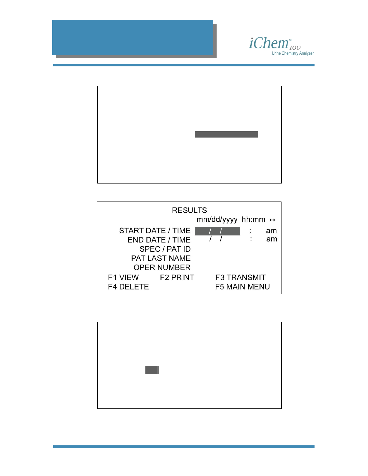
Chapter 6 - Results
Entering Microscopic Results.......................................................................................... 83
Viewing Results............................................................................................................... 88
Limiting Result Parameters .........................................................................................88
Printing Results............................................................................................................... 90
Transmitting Results .......................................................................................................92
Deleting Results.............................................................................................................. 93
Chapter 7 - Maintenance and Service
Maintenance.................................................................................................................... 95
Recommended Maintenance & Cleaning .................................................................... 95
Daily Maintenance ....................................................................................................... 95
Weekly Maintenance ................................................................................................... 96
Emptying Waste Container ...................................................................................... 96
Cleaning the Belt Assembly..................................................................................... 99
Replacing the Belts................................................................................................ 101
As needed - Replacing the Paper Roll ......................................................................104
Diagnostics.................................................................................................................... 105
300-4410 English Rev C 01/2007 Operators Manual 4
Page 6

Table of Contents
LCD Test ...................................................................................................................105
Printer Test................................................................................................................ 105
Load Drive Test ......................................................................................................... 106
Inc Drive Test ............................................................................................................106
LED Test.................................................................................................................... 106
RGB Test................................................................................................................... 107
Mechanical Tests....................................................................................................... 108
Internal Standard Test............................................................................................... 109
Exit Diagnostics......................................................................................................... 109
Before Calling for Service .............................................................................................110
Maintenance Log........................................................................................................... 111
Chapter 8 - Installation
Shipping Cartons........................................................................................................... 113
Unpacking .....................................................................................................................113
Installation..................................................................................................................... 114
Install the paper roll ...................................................................................................116
Appendix
Table of Results ............................................................................................................118
Bilirubin...................................................................................................................... 118
Urobilinogen ..............................................................................................................118
Ketones .....................................................................................................................118
Ascorbic Acid............................................................................................................. 118
Glucose .....................................................................................................................118
Protein ....................................................................................................................... 118
Blood Hemoglobin ..................................................................................................... 118
Blood (RBCs)............................................................................................................. 118
pH.............................................................................................................................. 119
Nitrite ......................................................................................................................... 119
Leukocytes ................................................................................................................119
Specific Gravity.......................................................................................................... 119
Color.......................................................................................................................... 119
Clarity ........................................................................................................................119
Specimen Type.......................................................................................................... 119
300-4410 English Rev C 01/2007 Operators Manual 5
Page 7

1. Introduction
1
Introduction
Introduction .......................................................................................................................7
Intended Use ................................................................................................................. 7
How to use the Operator’s Manual.................................................................................... 7
Precautions and Warnings ................................................................................................ 8
Notes ............................................................................................................................. 8
Cautions ........................................................................................................................8
Warnings .......................................................................................................................8
Biological Warnings....................................................................................................... 8
Warnings, Precautions, Limitations................................................................................... 8
Iris Diagnostics Contact Information .................................................................................9
Warranty............................................................................................................................ 9
Limitation of Liability........................................................................................................ 10
300-4410 English Rev C 01/2007 Operators Manual 6
Page 8

1. Introduction
Introduction
Intended Use
The iChem™100 Urine Chemistry Analyzer is a semi-automated urine
chemistry analyzer intended for use only with iChem™ 10 SG Urine
Chemistry Strips for the in vitro measurement of the following analytes in
urine: glucose, protein, bilirubin, urobilinogen, pH, specific gravity, blood,
ketones, nitrite, leukocytes, ascorbic acid, color and user-defined clarity.
This document is the Operators Manual for the iChem100 Urine Analyzer. It
is intended to explain system operation in detail and to be used as the
basis for training new operators. Retain this manual for future use. It is
an information guide and a troubleshooting reference. It explains
program settings and gives maintenance instructions.
How to use the Operator’s Manual
This manual contains important information on the functions of the
iChem100 distributed by Iris Diagnostics. This manual contains
instructions for the operation, maintenance and troubleshooting of the
iChem100.
Before operating the iChem100, read this manual carefully.
300-4410 English Rev C 01/2007 Operators Manual 7
Page 9
1. Introduction
Precautions and Warnings
The Operators Manual includes information and warnings that must be
observed by the operator in order to ensure safe operation of the system.
Important messages are highlighted with borders and special icons
identifying the type of message enclosed.
There are four types of messages: Notes, Cautions, Warnings and
Biological Warnings.
Notes
NOTE: Highlights important facts, gives helpful information and tips and
clarifies procedures.
Cautions
CAUTION: Electrical caution! Unplug before handling.
CAUTION: Important information on the proper operation of the
iChem100 Urine Analyzer. This information is crucial in preventing
instrument damage and maintaining the analyzer.
CAUTION: Laser light caution. A laser is used to read the barcodes.
Protect eyes from the laser light.
Warnings
WARNING: Identifies potentially hazardous situations that could result in
serious injury to laboratory personnel.
Biological Warnings
WARNING: Use care when handling urine samples or used test strips.
Always wear gloves to prevent exposure to pathogens. Incorrect or
imprecise procedures may result in exposure to pathogens. This unit
must only be used by operators trained in proper procedures for clinical
testing and handling of biohazardous waste.
Warnings, Precautions, Limitations
Do not place the iChem100 in water.
Do not drop or throw the instrument.
300-4410 English Rev C 01/2007 Operators Manual 8
Page 10

1. Introduction
Operate the instrument on a dry, level surface.
Do not move the instrument while a test is in process.
Plug the instrument into a grounded power source.
Avoid sources of bright light/heat.
Iris Diagnostics Contact Information
Customer opinion and input is extremely important to us. Iris Diagnostics
wants to design products that meet your needs. Comments on this
manual should be directed to:
Iris Diagnostics
Attention: Clinical Support
9172 Eton Avenue
Chatsworth, CA 91311
USA
Telephone
From U.S. and Canada locations +1-800-PRO-IRIS (776-4747)
From outside the U.S. +1-818-709-1244
Fax +1-818-700-9661
E-mail clinsupport@proiris.com
Warranty
Iris Diagnostics, a Division of IRIS International, Inc. (Iris) warrants that
the products manufactured by it or its affiliates and sold hereunder shall
be free from defects in material and/or workmanship, under normal use
and service, for the period expiring twelve (12) months from the
completion of installation, or upon Purchaser’s signature on Iris
Diagnostics Warranty/ Acceptance form, or fifteen (15) months from
shipment, whichever occurs first. No warranty extended by Iris
Diagnostics shall apply to any products which have been modified,
(including any third party software), altered, or repaired by persons other
than those authorized or approved by Iris Diagnostics or to products sold
as “used.”
Iris Diagnostics’ obligation under this warranty is limited SOLELY to the
repair or replacement, at Iris Diagnostics’ option, of defective parts,
F.O.B. warehouse or local Iris Diagnostics office, or as otherwise
300-4410 English Rev C 01/2007 Operators Manual 9
Page 11

1. Introduction
specified by Iris Diagnostics. Repairs or replacement deliveries shall not
interrupt or prolong the term of this warranty. Iris Diagnostics’ warranty
does not apply to consumable materials, except as specially stated in
writing, nor to products or parts thereof manufactured by the Purchaser.
This limited warranty is made on condition that immediate written notice
of any defect be given to Iris Diagnostics and that Iris Diagnostics
inspection reveals that the Purchaser’s claim is valid under the terms of
this warranty.
I
RIS DIAGNOSTICS MAKES NO WARRANTY OTHER THAN THE ONE SET FORTH
HEREIN OR THAT WHICH MAY BE PROVIDED IN A SEPARATE WARRANTY
COVERING THE APPLICABLE PRODUCT CATEGORY
IS IN LIEU OF ALL OTHER WARRANTIES
BUT NOT LIMITED TO ANY EXPRESSED OR IMPLIED WARRANTY OF
MERCHANTABILITY OR FITNESS FOR PARTICULAR PURPOSES AND SUCH
CONSTITUTES THE ONLY WARRANTY MADE WITH RESPECT TO THE PRODUCTS
. SUCH LIMITED WARRANTY
, EXPRESSED OR IMPLIED, INCLUDING
.
Limitation of Liability
Iris Diagnostics shall not be liable for any loss of use, revenue or
anticipated profits, or for any consequential or incidental damages
resulting from the sale or use of the products.
300-4410 English Rev C 01/2007 Operators Manual 10
Page 12

2. System Description
2
System Description
Theory of Operation ........................................................................................................ 12
Features ......................................................................................................................12
Test Strips ...................................................................................................................12
Optics ..........................................................................................................................13
LED Unit................................................................................................................... 13
CMOS Image Sensor............................................................................................... 14
Optics Calibration..................................................................................................... 14
Measurement ........................................................................................................... 14
Instrument Components.................................................................................................. 15
Front ............................................................................................................................ 15
Back............................................................................................................................. 15
Software.......................................................................................................................... 17
Data Entry Fields ......................................................................................................... 17
Toggle Fields............................................................................................................... 17
Function Keys .......................................................................................................... 18
Menu Diagram ............................................................................................................. 18
Main Menu ............................................................................................................... 18
Worklist Menu .......................................................................................................... 18
Run Patient Menu .................................................................................................... 19
Results Menu........................................................................................................... 19
Controls Menu.......................................................................................................... 19
Setup Menu.............................................................................................................. 20
Microscopic Menu .................................................................................................... 20
Service Menu ........................................................................................................... 20
Specifications.................................................................................................................. 21
Consumables or Part Replacement ................................................................................ 22
300-4410 English Rev C 01/2007 Operators Manual 11
Page 13

2. System Description
Theory of Operation
The iChem100 is a semi-automated urine chemistry analyzer performing
measurements of urine chemical constituents utilizing test strips. The
iChem100 is a reflectance densitometer.
Features
The iChem100:
• reads and interprets without operator variability
• processes and analyzes urine strips with a throughput of 210
samples per hour
• enables entry of microscopic results
Test Strips
• enables automated urine color determination with up to twelve
programmed choices
• reads ascorbic acid for interference detection
• allows users to correct or compensate for urine discoloration
• allows batch and stat mode for sample processing
The test strips have reagent-impregnated specialty paper pads to perform
c
hemical analysis of:
• bilirubin
• urobilinoge
n
• ketones
• ascorbic acid
• glucose
• protein
• blood
• pH
• nitrite
• leukocytes
• specific gravity
The advantage of this approach is ease of testing. The process requires
that an operator dip the urine test strip with its reagent-impregnated pads
into and out of a urine sample. This action brings the reagentimpregnated pads into contact with the urine containing the analytes to be
300-4410 English Rev C 01/2007 Operators Manual 12
Page 14
2. System Description
Optics
tested. Once the test strip has been dipped into the urine, color deve
on each of the reagent-impregnated pads in direct proportion to th
amount of analyte present in the sample. The test strips have a
compensation pad to determine the color of the urine as
fo
r color interference on the impregnated reagent pads.
After the test strips are placed on the Test Strip Tray with correct
orientation, they are automatically transported to the measurement
window and the r
the iChem100.
emainder of the operation is performed automatically by
well as correct
e
lops
LED Unit
For the illumination of the measurement, a LED Unit with three differen
wavelengths LEDs (450nm, 530nm and 625nm) is used. To increase
homogeneity, the LED’s are not placed regularly over the measurement
window but are placed mainly towards the outer area of the LED Unit.
order to achieve a very high light intensity, one reflector and one antireflector are placed beside the LED
e
ntire urine test strip is illuminated.
LED Unit Inside View Side View
300-4410 English Rev C 01/2007 Operators Manual 13
line. With this optical design, the
t
In
Page 15

2. System Description
CMOS Image Sensor
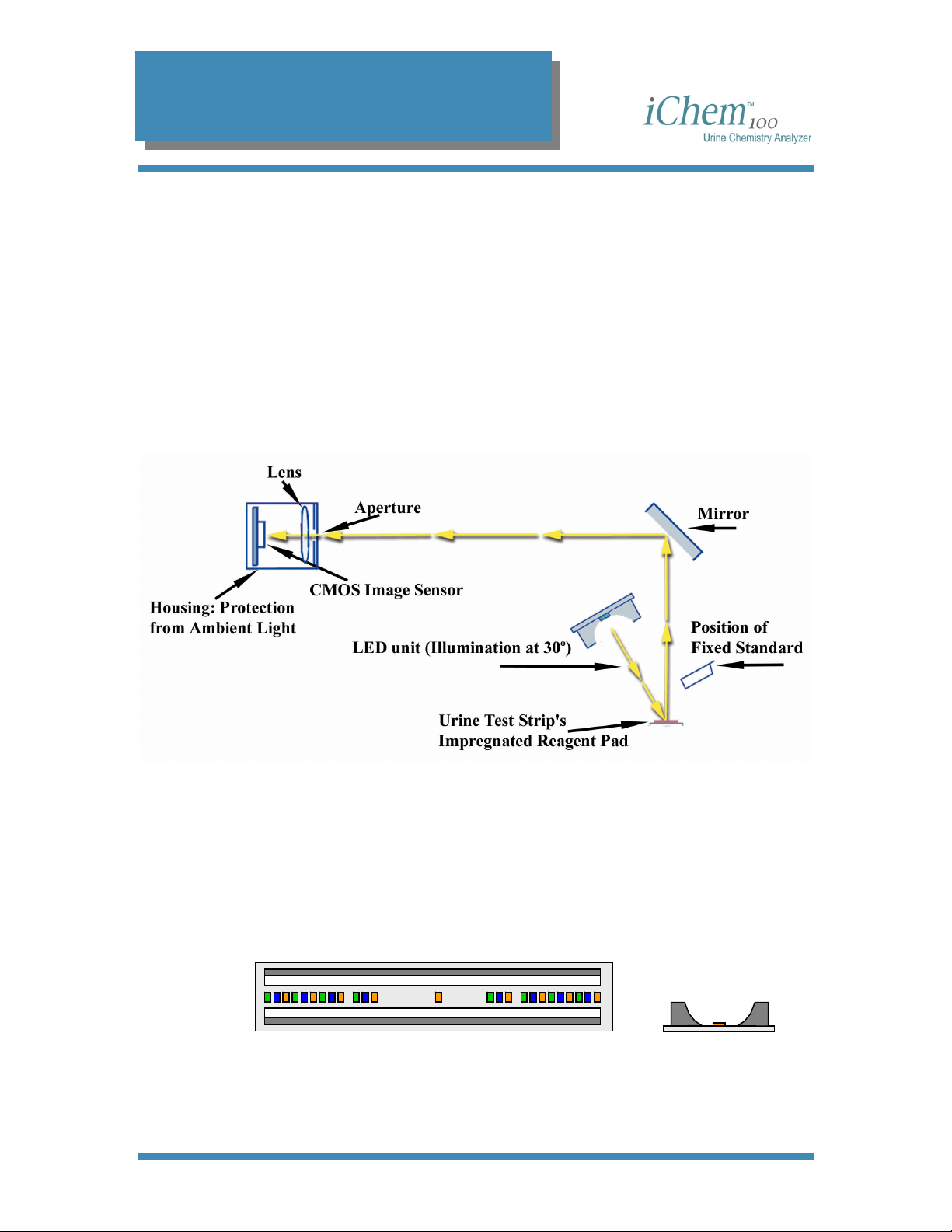
Unlike most of the reflectometers in the market for urine test strip
analysis, the iChem100 does not use a photodiode detector to measure
the reflected light, but instead utilizes a CMOS (Complementary Metal
Oxide Semiconductor) image sensor that captures a color image of each
of the test pads. The CMOS image sensor is able to photograph almost
the whole length (100mm) of the urine test strip and all of its width. As
seen in the figure above, the CMOS image sensor has been placed
perpendicular to the measurement level, and since the height of the
instrument limits the optical length, a mirror has been used for changing
the direction of the beam.
Optics Calibration
Prior to each measurement, the optics assembly is calibrated using a
“fixed standard” and it permits a one-point calibration. The iChem100 is
also capable of performing an internal, automated two-point calibration if
the one-point calibration done before each specimen determination falls
outside of the acceptable limits. A secondary “movable standard” is
automatically moved into place and readings from it in conjunction with
the “fixed standard” are used to perform a two-point calibration. No
external calibration strips or procedures are required.
Measurement
Once calibrated, the urine test strip is sequentially illuminated by the
LEDs (Red, Blue, Green) that are located at a 30
impregnated reagent pads, and the reflected signals are sent via the
mirror through the lens and captured by the CMOS camera. The captured
signal is evaluated and a completed result is provided for each of the
chemistries.
The iChem100 uses a compensation pad to determine the color of the
urine as well as correct for color interference on the impregnated reagent
pads. Since the iChem100 is capturing a pixelized image of the blood
pad, a special algorithm has been developed using more than a
reflectance to differentiate between intact and hemolyzed red blood cells.
º angle to the
300-4410 English Rev C 01/2007 Operators Manual 14
Page 16
2. System Description
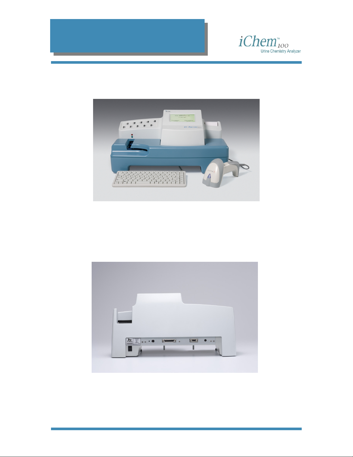
Instrument Components
Front
Back
3
6
4
5
2
7
1
1 - Keyboard
2 - Transport mechanism enclosure
3 - Display screen
4 - Paper roll
5 - Transport belt opening (for placement of strip)
6 - Clarity and specimen type barcode labels
7 - Hand-held barcode reader
5
1 - Power switch
2 - Keyboard/barcode reader cable connection
3 - External printer connection
4 - RS232 connection
5 - Power supply connection
1
2 3
4
300-4410 English Rev C 01/2007 Operators Manual 15
Page 17

2. System Description
Most user inputs are designed to be via the keyboard or the barcode
reader.
The keyboard is used for navigating within a screen, between screens,
making selections and entering data inputs.
The barcode reader enables you to enter information via barcoded data
into selected entry fields, (e.g., patient identification, specimen
identification, color, clarity, etc.).
300-4410 English Rev C 01/2007 Operators Manual 16
Page 18

2. System Description
Software
Data Entry Fields
Data entry fields are areas in a screen where information is entered. One
screen can have several data entry fields, but only one field can be
selected and active for entering data at a time. Pressing an alpha or a
numeric key will input that character into the data entry field. If you
exceed the number of allowable characters in a field, you cannot enter
more characters until some characters have been deleted.
To select a data entry field, use the keyboard [↑] or [↓] keys to move the
cursor up or down in the screen. To move back and forth between left
and right columns, use the [Tab] key. The contents of the field will be
reverse highlighted to show that they are selected or active.
To delete contents from a data field, select the field using the keyboard’s
[↑] or [↓] or [Tab] keys, then press the [Delete] key.
To erase contents from data field one character at a time, select the field
using the keyboard’s [↑] or [↓] or [Tab] keys, then press the [Backspace]
key. The last character in the field will be deleted.
Toggle Fields
Toggle fields are fields setup in a circular fashion allowing you to choose
one field out of a series of pre-setup fields (e.g., blank, trace, few,
moderate, many, etc.). A toggle field will be indicated by a doubleheaded arrow [↔]. Only one toggle field can be active at a given time.
To select a toggle field, use the keyboard keys [↑] or [↓] to move the
cursor into the desired field.
To view the choices in a toggle field, use the keyboard keys [←] or [→] to
advance through the selections. To switch back and forth from a left
toggle field to a right toggle field, press the [Tab] key.
To confirm or lock in a selection, you may press the [Enter] key or use
the keys [↑] or [↓]. Either one will lock in the selection and advance you
to the next field.
300-4410 English Rev C 01/2007 Operators Manual 17
Page 19

2. System Description
Function Keys
Pressing a function key, [F1] through [F10], will allow you to access the
described function associated with it. For example, to choose to run a
patient sample, press [F2] while the Main Menu screen is displayed. The
function keys will only perform the function that is associated with it in the
currently displayed screen.
Menu Diagram
Main Menu
03/10/2006 1:50PM
F1 WORKLIST F5 SETUP
MAIN MENU
F2 RUN PATIENT F6 MICROSCOPIC
F3 RESULTS F7 SERVICE
F4 CONTROLS
Worklist Menu
WORKLIST MENU
F1 CREATE
F2 DOWNLOAD
F3 VIEW/EDIT
F4 RUN
F5 PRINT
300-4410 English Rev C 01/2007 Operators Manual 18
Page 20
2. System Description
Run Patient Menu
Enter information, then place urine
strip on transport belt.
SEQ 003
SPEC/PAT ID
LAST NAME
FIRST NAME
CLARITY ↔
SPC TYPE ↔
Results Menu
RUN PATIENT
F1 MAIN MENU
Controls Menu
CONTROLS MENU
LOT# EXP
FILE 1 1212UC2006 03/20/2006
FILE 2 1213UC2006 03/20/2006
FILE 3
FREQ 1O Hours ↔
F1 SETP F2 VIEW F3 RUN
F4 PRINT F5 DELETE F6 MAIN MENU
300-4410 English Rev C 01/2007 Operators Manual 19
Page 21
2. System Description
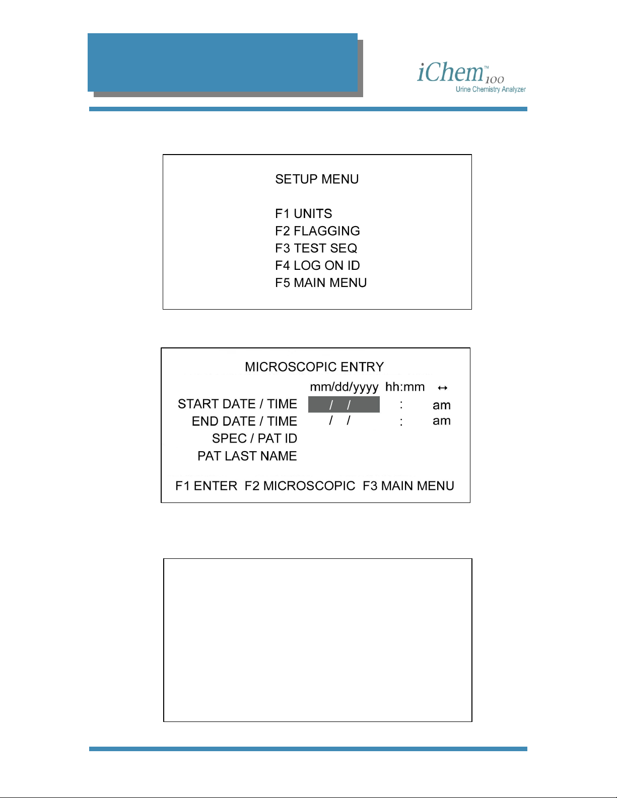
Setup Menu
Microscopic Menu
Service Menu
SERVICE MENU
F1 DATE/TIME F4 DIAGNOSTICS
F2 PRINTER F5 TRANSMIT
F3 LANGUAGE F6 TEST STRIP
F7 MAIN MENU
300-4410 English Rev C 01/2007 Operators Manual 20
Page 22
2. System Description
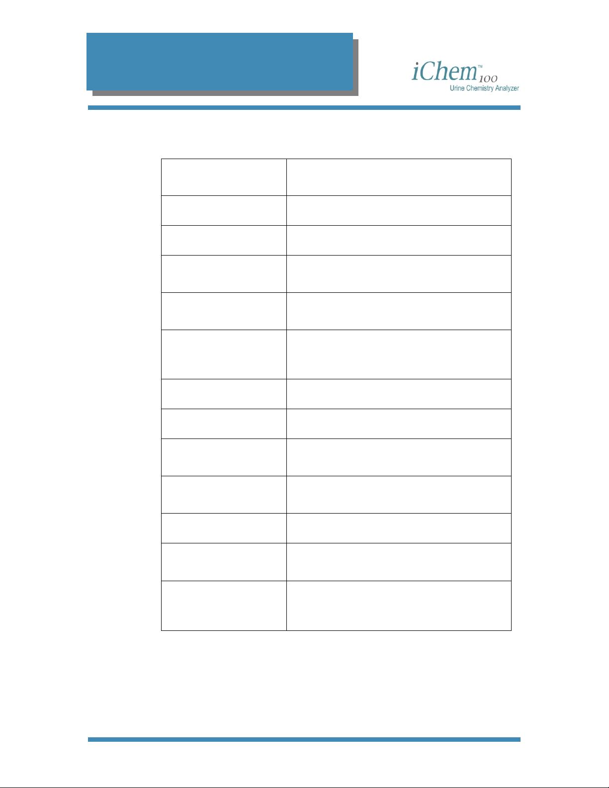
Specifications
Technology
Test Strips iChem 10 SG
Throughput 210 Urine Test Strips per hour
Data Storage
Reporting Units
Flagging
Display LCD backlit (8 lines x 40 characters)
Printer Thermal (built-in)
Interfaces
Reflectance Photometry LEDs (450nm,
520nm, 625nm) with Color Image Sensor
2,000 Patient results
300 Quality Control results
Conventional, S.I., Qualitative or
Combination
Results requiring confirmatory tests /
Microscopic examination
Abnormal Quality Control results
RS 232, parallel printer port,
5-pin DIN socket
Physical Specifications
Power 100 to 250 VAC ± 10%, 50/60 Hz
Operating Range
Package
300-4410 English Rev C 01/2007 Operators Manual 21
19.5 x 10.8 x 9.8 in (49.5 x 27.5 x 25 cm)
16.5 lbs (7.5 kg)
59° F to 90° F (15° C to 32° C)
20% to 80% Relative Humidity
iChem100 instrument
PC /AT keyboard
Hand-held barcode reader (Optional)
Page 23

2. System Description
Consumables or Part Replacement
REF Number
800-7504 Transport belts
800-7505 External power supply
800-7506 Power Supply Adapter
800-7507 Transport mechanism enclosure
800-7508 Barcode reader and cable
800-7509 Keyboard (English)
800-7510 Keyboard (German)
800-7511 3 Rolls of Thermal Paper
800-7014 Incubation Belt
800-7004 iChem 10 SG Urine Chemistry Strips (US)
800-7005 iChem 10 SG Urine Chemistry Strips (Int'l)
800-3203 Iris System Cleanser
Description
300-4410 English Rev C 01/2007 Operators Manual 22
Page 24

3. Set Up
3
Set Up
Setting the Language...................................................................................................... 24
Setting Date and Time .................................................................................................... 25
Setting the Date or Time Format ................................................................................. 26
Changing the Date and Time....................................................................................... 26
Setting the Reporting Units ............................................................................................. 28
Conventional (mg/dL) Units ......................................................................................... 29
Standard International (µmol/ L) units ......................................................................... 29
Qualitative (+) units ..................................................................................................... 29
Customized Units ........................................................................................................ 30
Printing Units ............................................................................................................... 30
Sample Print Layout................................................................................................. 31
Setting the Flagging Criteria............................................................................................ 32
Microscopic ..................................................................................................................... 34
Print a Copy of Microscopic Setup ..............................................................................36
Setting the Test Sequence.............................................................................................. 37
Setting the Log On Identifiers.......................................................................................... 39
Adding a New User...................................................................................................... 40
Editing a User Information ........................................................................................... 41
Deleting a User............................................................................................................ 43
Setting Up the Printer...................................................................................................... 45
Setting Transmitting Results ........................................................................................... 47
300-4410 English Rev C 01/2007 Operators Manual 23
Page 25
3. Set Up
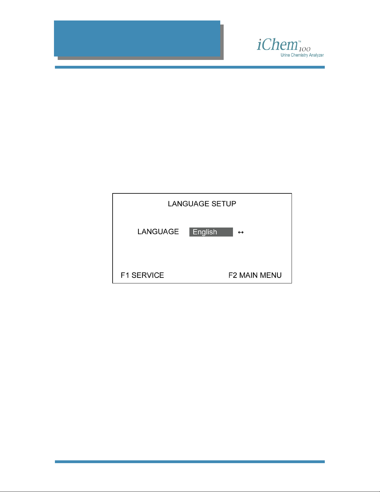
Setting the Language
This screen allows you to select the desired language with which to
display screens. The instrument can be set to one of six different
languages:
English Deutsch
Français Italiano
Español Português
1. From the Main Menu, press the [F7] key to access the Service
Menu.
2. From the Service Menu, press the [F3] key. The Language Setup
screen will be displayed.
3. Use the [←] or [→] arrow keys to toggle through the six language
options.
4. Press the [F1] key to lock in your selection and return to the Service
Menu screen, or press the [F2] key to lock in your selection and
return to the Main Menu screen.
300-4410 English Rev C 01/2007 Operators Manual 24
Page 26

3. Set Up
Setting Date and Time
This screen allows you to enter the correct date and time and select the
format for the instrument displays and printouts.
1. From the Main Menu, press the [F7] key. The Service Menu screen
will be displayed.
F1 DATE/TIME F4 DIAGNOSTICS
F2 PRINTER F5 TRANSMIT
F3 LANGUAGE F6 TEST STRIP
SERVICE MENU
F7 MAIN MENU
2. Press the [F1] key to display the Set Date/Time screen.
SET DATE / TIME
DATE FORMAT mm/dd/yyyy
TIME FORMAT am / pm
DATE 03/23/2006
TIME 10:00 pm ↔
F1 FORMAT F2 SERVICE F3 MAIN MENU
300-4410 English Rev C 01/2007 Operators Manual 25
Page 27

3. Set Up
Setting the Date or Time Format
1. From the Set Date/Time screen, press the [F1] key to display the
Format Date/Time screen.
2. Use the [←] or [→] arrow keys to toggle through three date options:
• dd.mm.yyyy
• mm/dd/yyyy
• yyyy/mm/dd
3. Press the [↑] or [↓] arrow keys, or the [Enter] key to lock in your
selection and move to the next field.
4. Use the [←] or [→] arrow keys to toggle through the two time options:
• 24 hour
• am/pm
5. Press the [F1] key to return to the Date/Time screen.
Changing the Date and Time
1. From the Date/Time screen, use the [↑] or [↓] arrow keys or the
[Enter] key to move to the desired field (e.g., DATE, TIME or am/pm).
2. To enter or change the date, select the DATE field, and then enter the
correct date using the keyboard numeric keys.
NOTE: You must enter two digits for the month and the day (e.g., 01
for January, etc.)
300-4410 English Rev C 01/2007 Operators Manual 26
Page 28
3. Set Up
3. To enter or change the time, select the TIME field, and then enter the
correct time using the keyboard numeric keys.
NOTE: You must enter two digits for the hour and the minutes (e.g.,
01:01 for 1:01, etc.).
4. To change the am/pm selection (if desired), select the am/pm field,
use the [←] or [→] arrow keys to select am or pm.
5. Press the [F2] key to return to the Service Menu screen, or press the
[F3] key to return to the Main Menu screen.
300-4410 English Rev C 01/2007 Operators Manual 27
Page 29

3. Set Up
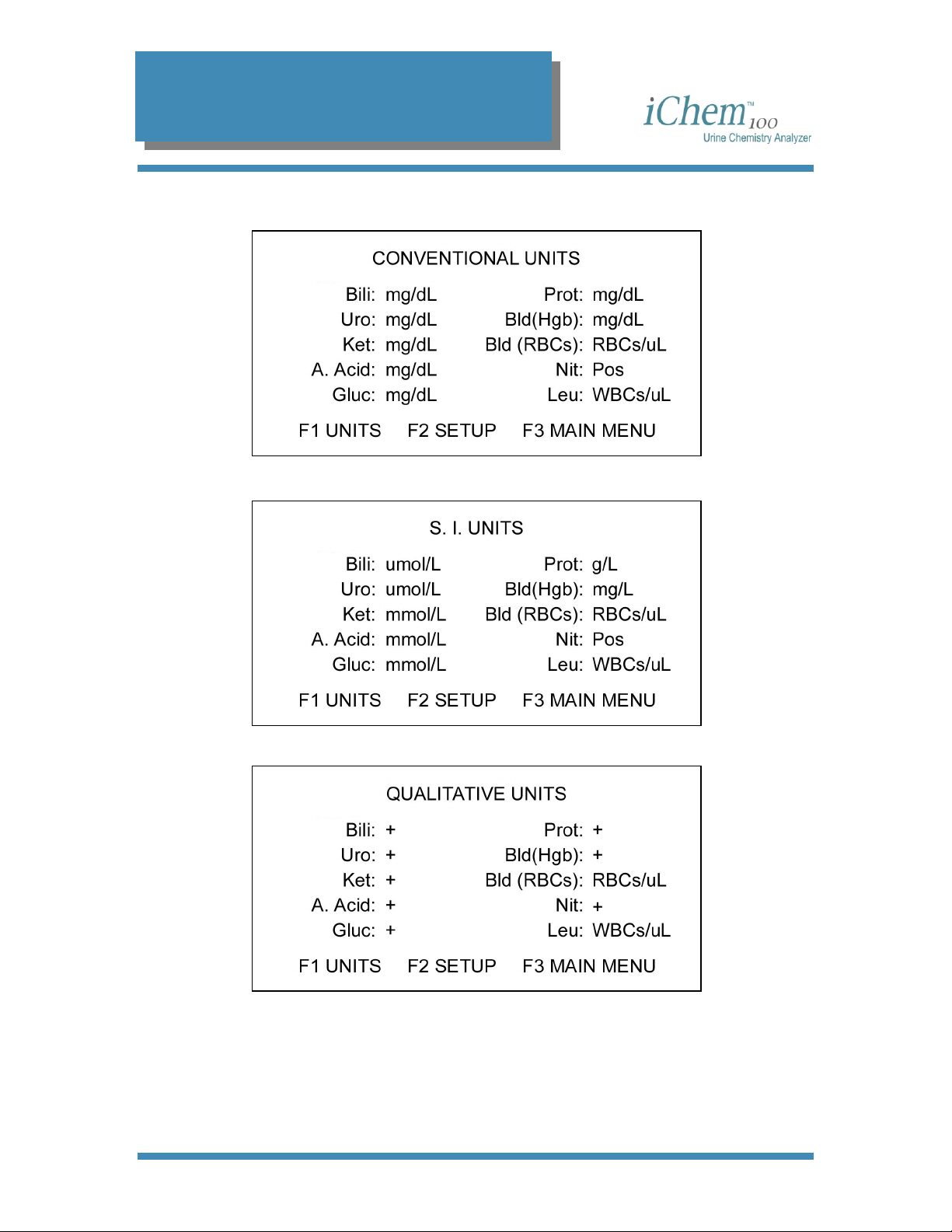
Setting the Reporting Units
This screen allows you to select the reporting units for the results of the
test strips chemistries. You may select from the following options:
• Conventional (mg/dL)
• S.I. (Standard International—µmol/L and mmol/L)
• Qualitative (+)
• Customized (a combination of all three)
1. From the Main Menu, press the [F5] key. The Setup Menu will be
displayed.
2. From the Setup Menu, press the [F1] key. The Units screen will be
displayed.
3. To select either conventional, S.I., or qualitative units exclusively,
select the desired unit option using the [↑] or [↓] arrow keys, then
press the [F1] function key.
300-4410 English Rev C 01/2007 Operators Manual 28
Page 30
3. Set Up
Conventional (mg/dL) Units
Standard International (µmol/ L) units
Qualitative (+) units
Press the [F1] key to return to the Units screen from any of these display
screens.
300-4410 English Rev C 01/2007 Operators Manual 29
Page 31

3. Set Up
Customized Units
This option allows you to report out chemistry results with units
specifically selected for each of the chemistries.
1. From the Units screen, select Customized (mg/dL or µmol/L or +)
using the [↑] or [↓] arrow keys, then press the [F1] key. The
Customized Units screen will be displayed.
2. Toggle through the unit selections for the first chemistry using the [←]
3. Continue until all unit selections have been made, then press the [F1]
Printing Units
1. From the Units screen, select the desired units and then press the
2. Press the [F1] key to stop printing, if desired. Press the [Pg Up] key
or [→] arrow keys. Once the desired units are displayed, press the [↓]
arrow key, or [Tab] key, or the [Enter] key to move to the next
chemistry unit field.
key to lock in the selections and return to the Units screen.
[F2] key. The instrument will begin printing the selected units.
to feed the paper into the printer.
300-4410 English Rev C 01/2007 Operators Manual 30
Page 32

3. Set Up
Sample Print Layout
The figure below displays an example of a unit printout.
300-4410 English Rev C 01/2007 Operators Manual 31
Page 33

3. Set Up
Setting the Flagging Criteria
This option allows you to adjust flagging criteria for each chemistry to
your own patient population. The flagging defaults in the instrument are
set to the first positive level for each chemistry test. Any chemistry result
at or higher than the selected positive result will be flagged when printed
or displayed.
1. From the Setup Menu, press the [F2] key. The Flagging Setup
screen will be displayed.
2. Toggle through the result selections for the first chemistry using the
[←] or [→] arrow keys. The field will display all positive reportable
results for the units selected. Once your selection is displayed, press
the [↓] arrow key, the [Tab] key, or the [Enter] key to move to the
next chemistry unit field.
3. When all flagging selections have been made, press the [F1] key to
lock in the selections. The Flag Selection screen, which allows you to
determine how each chemistry will be flagged, will be displayed.
300-4410 English Rev C 01/2007 Operators Manual 32
Page 34

3. Set Up
For example, an asterisk (*) may be used to signal an abnormal result
and that an additional confirmation test is required. The use of a number
sign (#) may signal that a microscopic examination is required.
4. Toggle through the flagging selections for the first chemistry using the
[←] or [→] arrow keys. The flagging choices are:
• Blank - no flag will be displayed
•
* - displays an asterisk after the result
•
# - displays a number sign after the result
5. Once your selection is made, press the [↓] arrow key, the [Tab] key
or the [Enter] key to move to the next field.
6. When all flagging selections have been made, press the [F1] key to
lock in the selections and return to the Flagging Setup screen.
• Press the [F2] key to lock in the selection and return to the
Setup Menu screen.
• Press the [F3] key to lock in the selection and return to the
Main Menu screen.
300-4410 English Rev C 01/2007 Operators Manual 33
Page 35

3. Set Up
Microscopic
This function provides you with the means to set up your preferences for
reporting microscopic exams performed on urine specimens, print out
your set up quantifiers, as well as the ability to enter microscopic results.
1. From the Main Menu, press the [F6] key. The Microscopic screen is
displayed.
NOTE: Since the setup information becomes the basis for the quantifiers
used in reporting microscopic exams, anytime this information is altered,
all existing patient data is deleted to avoid reporting the wrong
microscopic information. A warning screen will alert you to this prior to
allowing you to establish the new microscopic quantifiers.
2. From the Microscopic screen, press the [F2] key to display the
following Microscopic Setup screen.
A series of screens similar to this one provide you with the ability to
record, display, and print microscopic examinations consistent with
reporting results for the specified parameter for your laboratory.
300-4410 English Rev C 01/2007 Operators Manual 34
Page 36

3. Set Up
For example, shown above is the screen for entering quantifiers for
RBC’s. You have six text fields in which to enter the descriptors
consistent with your laboratory’s results for RBC’s, e.g., trace, 1+, 1-3
HPF, etc. Each text field will hold up to 10 alphanumeric characters.
Once entered, these fields will be the toggle fields used when you
select the quantities present in the microscopic exam for RBC’s.
3. To enter a microscopic quantifier for a parameter, type the desired
information into the text field, then press the [↑] or [↓] arrow keys, the
[Tab] key or the [Enter] key to move to the next field. The [Delete]
key can be used to delete existing entries in the field allowing the
operator to change the information.
4. Once you have entered all the quantitative descriptions desired for the
current parameter, press the [F1] key to bring up the next microscopic
parameter screen.
5. To enter the quantifiers for the next microscopic parameter, type the
desired information into each of its text fields, then press the [↑] or [↓]
arrow keys, the [Tab] key or the [Enter] key to move to the next field.
To go back to the previous parameter, press the [F2] key.
There are a total of 11 parameters listed. Each parameter has up to
six fields in which to enter quantitative results. The parameters are as
follows:
• RBCs (red blood cells)
• WBCs (white blood cells)
• Bacteria
• Epis (Epithelial cells)
• Crystals
• Yeast
300-4410 English Rev C 01/2007 Operators Manual 35
Page 37

3. Set Up
• Casts
• Trich (Trichomonas)
• Oval fat (Oval fat bodies)
• Mucus
• Sperm
6. Continue entering parameter quantifier information until you have
entered it for all parameters desired. Press the [F3] key to return to
the Microscopic screen or press the [F4] key to return to the Main
Menu screen.
Print a Copy of Microscopic Setup
1. From the Microscopic screen, press
the [F3] key to print a copy of the
microscopic parameters.
2. Press the [F1] key to stop printing, if
desired.
All printouts will include:
Header information (see
Up the Printer
The printout identifier:
Microscopic Setup.
Each parameter with up to six
quantifiers.
.)
Setting
300-4410 English Rev C 01/2007 Operators Manual 36
Page 38

3. Set Up
Setting the Test Sequence
This screen allows you to display and print the individual chemistry tests
in a specific order. The default test setup sequence is shown below.
1. From the Setup Menu, press the [F3] key to display the Test
Sequence Setup screen.
2. To change the sequence order of any of the chemistries, select the
field next to the chemistry and using the keyboard, enter a number
from 1 to 11.
3. Once your selection is made, press the [↓] arrow key, the [Tab] key
or the [Enter] key to move to the next field.
• If a test result is not to be displayed or printed, do not enter a
number next to that test parameter.
• You may not use the same number in more than one field. To do
so will result in an error when you go to lock in the selections.
4. When all test selections have been numbered, press the [F1] key to
lock in the selections and display the default reporting order for the
microscopic examination.
300-4410 English Rev C 01/2007 Operators Manual 37
Page 39

3. Set Up
5. To change the sequence order of any of the microscopic parameters,
select the field next to the microscopic results and using the keyboard,
enter a number between 1 and 13.
6. Once your selection is made, press the [↑] or [↓] arrow keys, the
[Tab] key or the [Enter] key to move to the next desired parameter
field.
• If a result is not to be displayed or printed, do not enter a number
next to that test parameter.
• You may not use the same number in more than one field. To do
so will result in an error when you go to lock in the selections.
7. When all desired test selections have been numbered, press the [F1]
key to return to the Test Sequence Setup screen displaying the
chemistry parameters.
• Press the [F2] key to return to the Setup Menu screen.
• Press the [F3] key to return to the Main Menu screen.
300-4410 English Rev C 01/2007 Operators Manual 38
Page 40

3. Set Up
Setting the Log On Identifiers
This function allows you to record the operator who performed an
analysis along with the results of the specimen by requiring users to log
onto the instrument.
If Log On Required is selected, a user must “Log On” to operate the
instrument. The instrument will automatically display the “Log On” screen
before allowing the operator to access the Main Menu.
If Log On Not Required is selected, the instrument will go directly to the
Main Menu screen when turned on.
NOTE: A generic “Log On” will permit operation of the instrument should
the operator forget their password.
1. From the Setup Menu, press [F4] to access the Log On Setup
screen.
2. To require “Log On” to the iChem100 instrument, select Log On
Required on the Log On Setup screen.
3. Once the “Log On Required” is highlighted, press either [F1] or [F2]
and the instrument will automatically take you to the Enter Log On ID
screen.
4. Type iris (all lowercase) in the “Enter Log On ID” field and press [F1].
The instrument will take you to the Main Menu screen.
If you enter the password incorrectly, an error message will appear
advising you to re-enter the password.
300-4410 English Rev C 01/2007 Operators Manual 39
Page 41

3. Set Up
Adding a New User
This option allows you to add a “Log On ID” to be used when logging on
to the analyzer. A “Log On ID” must be specific for an operator and must
be in lowercase only, last and first names can include uppercase. Up to
24 users can be entered. The software will check to insure that an
identifier is not currently in use by another operator. If a desired identifier
is already in use, you will be notified, the “Log On ID” field will be blanked
and you will be asked to enter a new identifier
1. From the Main Menu, press [F5] to access the Setup Menu.
2. Press [F4] to access the Log On Setup screen.
3. Press [F1] to display the Log On Setup Change or Delete screen.
4. Use the [↓] arrow key to advance to the first empty position. Press
[F2] to display the Log On ID Setup—Add/Change screen.
5. Enter the operator’s last name in the “Last Name” text field (up to 15
alpha characters). Press the [Enter] key or use the [↑] or [↓] arrow
keys to advance to the next field.
6. Enter the operator’s first name in the “First Name” text field (up to 10
alpha characters). Press the [Enter] key or use the [↑] or [↓] arrow
keys to advance to the next field.
7. Enter a personal identifier in the “Log On ID” text field (between 4 and
10 lower case alphanumeric characters). Press the [Enter] key or
use the [↑] or [↓] arrow keys to advance to the next field.
8. Re-enter the personal identifier in the “Verify Log On ID” text field.
300-4410 English Rev C 01/2007 Operators Manual 40
Page 42

3. Set Up
9. Press any [F] key displayed on the screen. The software will
automatically accept the Log On ID identifier unless:
the entered “Log On” identifier and the Verify Log On Identifier
do not match
the entered “Log On” identifier is already in use
no information was entered, or insufficient information was
entered
In these cases, a screen will appear identifying the error and it will allow
you to either:
[F1] return to the previous screen to correct the deficiency,
[F2] disregard and return to the Setup menu without the “Log
On” ID being setup,
[F3] disregard and return to the Main Menu without the “Log
On” ID being setup.
10. Press the [F1] key to return to the Log On Setup screen.
11. Press the [F2] key to return to the Setup Menu screen, or press the
[F3] key to return to the Main Menu screen.
Editing a User Information
1. If an operator is “Logged On”, he/she must “Log Off” and log back on:
a. From the Main Menu, press [F8] to display the Enter Log ON
ID screen.
b. Type iris as a generic Log On ID and then press the [F1] key.
2. From the Main Menu, press [F5] to display the Setup Menu screen,
then [F4] to display the Log On Setup screen, and then press [F1] to
display the Log On Setup Change or Delete screen.
300-4410 English Rev C 01/2007 Operators Manual 41
Page 43

3. Set Up
3. Press the [F1] key if the desired operator name is not displayed on
this screen. This will advance you to the next screen of operator
names.
A total of 24 positions are available.
4. Once the desired operator name is displayed on the screen, use the
[↑] or [↓] arrow keys or the [Enter] key to select it.
5. Press the [F2] key. A message will appear warning that all results will
be deleted.
WARNING: All stored results will be deleted from memory
6. Press the [F1] key to continue. This will display the Log On ID
Setup—Add/Change screen.
7. To change any of the information shown, use the [↑] or [↓] arrow keys
to move to the desired text field to highlight it.
8. Enter the change desired using the keyboard keys.
NOTE: If you make an entry in the “Log On ID” field, you must make the
same entry in the “Verify Log On ID” field.
9. Press the [F1] key to lock in the changes made and return to the Log
On Setup screen.
10. Press the [F2] key to lock in the changes made and return to the
Setup Menu screen, or press the [F3] key to log in the changes made
and return to the Main Menu screen.
300-4410 English Rev C 01/2007 Operators Manual 42
Page 44

3. Set Up
Deleting a User
1. If an operator is Logged On using their own identifier, they must Log
Off and log back on using the generic “iris” (all lower case) “Log On
ID”.
2. Press [F5] to display the Setup Menu screen, then [F4] to display the
Log On Setup screen, and finally press [F1] to display the Log On
Setup Change or Delete screen. This screen will allow you to delete
one or more “Log On” identifiers.
3. Press the [F1] key if the desired operator name is not present on this
screen. This will advance you to the next screen of operator names.
4. Use the [↑] or [↓] arrow keys or the [Enter] key to select the user.
5. If you wish to delete the selected (highlighted) operator information,
press the [F3] key. A message will appear warning that all results will
be deleted.
6. If you press the [F1] key, the Log On Setup Delete screen will be
displayed.
300-4410 English Rev C 01/2007 Operators Manual 43
Page 45

3. Set Up
7. If you press the [F2] key the Log On Setup screen will be displayed,
or pressing the [F3] key the Main Menu screen will displayed.
8. If you selected the [F1] option above, use the [↑] or [↓] arrow keys or
the [Enter] key to select (highlight) your choice.
9. If you select YES and press the [F1] key, the instrument will delete
the existing operator information and return you to the Log On Setup
Change or Delete screen.
If you select NO and press the [F1] key, the instrument will return you
to the Log On Setup Change or Delete screen without deleting the
operator information.
300-4410 English Rev C 01/2007 Operators Manual 44
Page 46

3. Set Up
Setting Up the Printer
1. To set up the printer functions, press the [F7] key with the Main Menu
screen active, then press the [F2] key with the Service Menu screen
active. The Printer Setup screen will be displayed.
This screen allows you to configure certain printer functions as well as
configure the printout header.
2. The printer can be set to print using one of three options:
Internal—printing will be on the instrument printer only
External (Letter)—printing will be sent to an external printer that
uses letter size paper
External (A4) – printing will be sent to an external printer that uses
A4 size paper
3. Use the [←] or [→] arrow keys to toggle through the options, then use
the [↑] or [↓] arrow keys, or the [Enter] key to lock in the selection
and move to the next field.
4. The Print Cycle can be set to print:
After each Analysis/Run—printer will print results after each
analysis or “worklist” run
Print Function only—printer will print results only when the Print
Function keys are selected
5. Use the [←] or [→] arrow keys to toggle through the options, then use
the [↑] or [↓] arrow keys, or the [Enter] key to lock in the selection
and move to the next field.
300-4410 English Rev C 01/2007 Operators Manual 45
Page 47

3. Set Up
6. The Operator print function allows the laboratory to print, if desired,
the name or number of the operator performing the tests with the
corresponding results using one of three options:
Number—printer will print the operator identifier number on each
printout
Name—printer will print the operator name on each printout
Blank—printer will not print operator ID or name on printout
The remaining fields on this screen allow you to create the print header
to be displayed and printed when results are sent to the printer.
7. Four lines with up to 30 alphanumeric characters each may be
entered. Once you have entered the desired information, use the [↑]
or [↓] arrow keys, or the [Enter] key to lock in the selection and move
to the next line.
8. Press the [F1] key to lock in your selection and return to the Service
Menu screen, or press the [F2] key to lock in your selection and
return to the Main Menu screen.
300-4410 English Rev C 01/2007 Operators Manual 46
Page 48

3. Set Up
Setting Transmitting Results
This function provides you with the ability to configure when to transmit
data to your host computer.
1. From the Main Menu screen, press the [F7] key, then press the [F5]
key. The Transmit Setup screen will be displayed.
2. The instrument can be set to transmit using one of two options:
After each Analysis/Run - data will be transmitted to the host
computer after each analysis/run
Transmit Function Only - data will be transmitted only when the
transmit function [F3] is accessed from the Results screen.
3. To setup the Transmit option, use the [←] or [→] arrow keys to toggle
through the two options, then use the [↑] or [↓] arrow keys, or the
[Enter] key to lock in the selection and move to the next field.
4. Press the [F1] key to return to the Service Menu screen, or press the
[F2] key to return to the Main Menu screen.
300-4410 English Rev C 01/2007 Operators Manual 47
Page 49

4. Specimen Processing
4
Specimen Processing
Powering the Instrument On ........................................................................................... 49
Logging On .................................................................................................................. 49
Logging Off.................................................................................................................. 50
Running Single Specimen Analysis ................................................................................ 51
Entering Patient Information ........................................................................................ 51
Sequence Number ................................................................................................... 51
Specimen/Patient ID ................................................................................................ 51
Last Name................................................................................................................ 51
First Name ............................................................................................................... 52
Clarity....................................................................................................................... 52
Spec Type................................................................................................................ 53
Analyzing the Urine .....................................................................................................54
Running Batch Specimen Analysis ................................................................................. 57
Creating a Worklist ...................................................................................................... 57
Sequence Number ................................................................................................... 59
Specimen/Patient ID ................................................................................................ 59
Last Name................................................................................................................ 59
First Name ............................................................................................................... 59
Clarity....................................................................................................................... 59
Spec Type................................................................................................................ 60
Downloading a Worklist............................................................................................... 62
Viewing and Editing a Worklist .................................................................................... 63
Running a Worklist ......................................................................................................65
Printing a Worklist........................................................................................................ 67
Running a Stat ................................................................................................................68
300-4410 English Rev C 01/2007 Operators Manual 48
Page 50

4. Specimen Processing
Powering the Instrument On
When powered on, the instrument will perform an internal systems check
and then go directly to the screen shown below, unless “Log On
Required” has been previously selected.
iChem100
URINE CHEMISTRY ANALYZER
F1 MAIN MENU
Boot Program: Meter Program:
2.01.01 2.01.01
Press [F1] to proceed to the Main Menu screen. Prior to displaying the
Main Menu screen, the display will ask whether you have emptied the
waste container or not. Press [F1] if not emptied or [F2] if emptied, and
the Main Menu screen will be displayed.
NOTE: Anytime the transport mechanism enclosure is removed while the
instrument is on, you will be alerted that it is ajar and you must indicate
whether the waste container was emptied or not. Once it is back in place,
the incubation belt will run for approximately 110 seconds to clear any
strips that may be on the belts and then the Main Menu screen will
appear.
Logging On
The following screen is displayed when you power up of the iChem100
instrument if the Log On Required option has been selected in the Setup
Menu. Refer to
1. Press the [F1] key to advance to the Enter Log On ID screen shown
Setting Log On Identifiers.
below.
300-4410 English Rev C 01/2007 Operators Manual 49
Page 51

4. Specimen Processing
2. Enter your assigned identifier using the keyboard keys. To delete
entered characters, press the [Backspace] key.
3. Press the [F1] key to enter your identifier and advance to the Main
Menu screen.
03/10/2006 1:50PM
Logging Off
To log off of the instrument, from the Main Menu, press the [F8] key. This
will log off the current operator and the Enter Log On ID screen will be
displayed. The [F8] LOG OFF does not appear on the Main Menu screen
unless “Log On Required” is selected.
MAIN MENU
F1 WORKLIST F5 SETUP
F2 RUN PATIENT F6 MICROSCOPIC
F3 RESULTS F7 SERVICE
F4 CONTROLS F8 LOG OFF
NOTE: If the Enter Log On ID screen reappears with the message
“Unacceptable Log On”, re-enter your identifier. If the Main Menu
screen still does not appear, refer to Setting Log On Identifiers.
300-4410 English Rev C 01/2007 Operators Manual 50
Page 52

4. Specimen Processing
Running Single Specimen Analysis
Entering Patient Information
1. From the Main Menu screen, press the [F2] key to display the Run
Patient screen (below) and to activate the urine strip sensor. The
illuminated green LED on the instrument indicates that the sensor is
active.
NOTE: If the waste container is nearly full (> 125 strips), you must
empty it prior to beginning “Run Patient” analysis.
The Run Patient screen allows you to identify and run a patient
specimen. You can identify the sample using a sequence number, a
specimen/patient ID, a name, or all three options. Data for only one
patient at the time can be entered in this screen.
Sequence Number
The sequence number field is only active for the first specimen run
after entering Run Patient. Thereafter, the sequence number is
automatically assigned by the software each time a new patient
specimen is analyzed.
Specimen/Patient ID
2. If desired, enter specimen or patient ID (up to 15 alphanumeric
characters) by using the keyboard or the barcode reader. Press the
[Enter] key or use the [↑] or [↓] arrow keys to move to the next field.
Last Name
3. If desired, enter the patient last name (up to 15 characters) using the
keyboard or the barcode reader. Press the [Enter] key or use the [↑]
or [↓] arrow keys to move to the next field.
300-4410 English Rev C 01/2007 Operators Manual 51
Page 53

4. Specimen Processing
First Name
4. If desired, enter the patient first name (up to 10 characters) using the
keyboard or the barcode reader. Press the [Enter] key or use the [↑]
or [↓] arrow keys to move to the next field.
Clarity
5. You can enter clarity by either toggling through the list of clarity
options found in the software or by using the barcode reader.
Barcodes are located at the top left of the instrument.
Using keyboard entry Using barcode entry
Options Blank field
Clear
Hazy
Slt. Cloudy
Cloudy
Turbid
Bloody
Other
Press the [←] or [→] arrow keys
until the desired clarity result
appears. Press the [Enter] key or
use the [↑] or [↓] arrow keys to
accept and move to the next field.
Options CLEAR
SLT. CLOUDY
CLOUDY
BLOODY
OTHER
To select clarity using the
barcode reader, determine the
clarity result and click the
barcode reader over its
respective barcode.
300-4410 English Rev C 01/2007 Operators Manual 52
Page 54

4. Specimen Processing
Specimen Type
6. You can enter the specimen type by either toggling through the list in
the software or by using the barcode reader. Barcodes are located at
the top left of the instrument.
Using keyboard entry Using barcode entry
Options Blank field
Random
CL catch
Cath
Peds
First am
24 hours
Fasting
Gluc tol
S pubital
Other
Press the [←] or [→] arrow keys
until the desired type appears.
Press the [Enter] key or use the
[↑] or [↓] arrow keys to accept
and move to the next field.
Options RANDOM
CL CATCH
CATH
PEDS
OTHER
To select specimen type using
the barcode reader, click the
barcode reader over its
respective barcode.
300-4410 English Rev C 01/2007 Operators Manual 53
Page 55

4. Specimen Processing
Analyzing the Urine
Once all the patient identification information has been entered, proceed
to analyzing the urine.
NOTE: The urine specimen should be fresh, well-mixed and uncentrifuged. If refrigerated, allow the specimen to return to room
temperature.
1. Dip the urine test strip into the urine, making sure all the test pads are
wet.
2. Immediately remove the urine test strip from the urine, dragging the
edge of the strip against the side of the container as you remove the
strip.
3. Blot the urine test strip by touching the edge of the strip to a paper
towel. Do not drag the strip across the paper towel; touch the edge
only.
300-4410 English Rev C 01/2007 Operators Manual 54
Page 56

4. Specimen Processing
4. Place the urine test strip on the transport belt of the instrument with
the test pads facing up. Slide the strip forward until the strip touches
the end stop. A sensor will detect the presence of the strip and the
red LED light will be turned on along with the green LED light.
NOTE: If you move the strip away from the sensor prior to being
transported, you will be prompted to remove the urine strip from the
transport belt and press the [F1] key to continue.
5. Approximately two minutes after the urine strip is transported for
analysis the printer will print the results; unless printing has been set
to “Print Function Only” (see
300-4410 English Rev C 01/2007 Operators Manual 55
Setting up the printer.)
Page 57

4. Specimen Processing
To run another specimen, repeat from
then
Analyzing the Urine. If no test strip is placed on the transport belt
within ten (10) minutes, the screen will return to the Main Menu screen.
You may return to the Main Menu screen at any time by pressing the [F1]
key. However, if the analysis of the strip is not complete, a message will
appear requesting that you wait for analysis to finish.
Entering Patient Information,
300-4410 English Rev C 01/2007 Operators Manual 56
Page 58

4. Specimen Processing
Running Batch Specimen Analysis
Creating a Worklist
The Create Worklist screen allows you to generate a list of specimen
samples that will run in a batch mode. To create a worklist, you must
enter information in at least one of the identifier fields. An error message
will direct you to enter missing information before advancing to the next
specimen. The sequence number field is only active for the first
specimen in the Create Worklist option. After the first specimen, the
instrument will automatically advance one sequence number each time a
new patient specimen is entered.
1. From the Main Menu screen, press the [F1] key to display the
Worklist Menu screen.
2. From the Worklist Menu screen, press the [F1] key to display the
Create Worklist screen.
300-4410 English Rev C 01/2007 Operators Manual 57
Page 59

4. Specimen Processing
3. The following screen will appear only if a worklist exists. Use the [↑]
or [↓] arrow keys to select YES or NO.
a. If you select YES and press the [F1] key, the instrument will
delete the existing worklist and advance you to the Create
Worklist screen.
b. If you select NO and press the [F1] key, the instrument will return
you to the Worklist Menu screen.
300-4410 English Rev C 01/2007 Operators Manual 58
Page 60

4. Specimen Processing
Sequence Number
4. To reset the sequence number, change it while the initial specimen
screen is active or you will need to return to the initial specimen
screen in the worklist where the sequence number field will again be
active.
Specimen/Patient ID
5. If desired, enter specimen or patient ID (up to 15 alphanumeric
characters) by using the keyboard or the barcode reader. Press the
[Enter] key or use the [↑] or [↓] arrow keys to move to the next field.
Last Name
First Name
Clarity
6. If desired, enter the patient last name (up to 15 characters) using the
keyboard or the barcode reader. Press the [Enter] key or use the [↑]
or [↓] arrow keys to move to the next field.
7. If desired, enter the patient first name (up to 10 characters) using the
keyboard or the barcode reader. Press the [Enter] key or use the [↑]
or [↓] arrow keys to move to the next field.
8. You can enter clarity by either toggling through the list of clarity
options found in the software or by using the barcode reader.
Barcodes are located at the top left of the instrument.
300-4410 English Rev C 01/2007 Operators Manual 59
Page 61

4. Specimen Processing
Using keyboard entry Using barcode entry
Options Blank field
Clear
Hazy
Slt. Cloudy
Cloudy
Turbid
Bloody
Other
Press the [←] or [→] arrow keys
until the desired clarity result
appears. Press the [Enter] key or
use the [↑] or [↓] arrow keys to
accept and move to the next field.
Options CLEAR
SLT. CLOUDY
CLOUDY
BLOODY
OTHER
To select clarity using the
barcode reader, determine the
clarity result and click the
barcode reader over its
respective barcode.
Specimen Type
9. You can enter the specimen type by either toggling through the list in
the software or by using the barcode reader. Barcodes are located at
the top left of the instrument.
300-4410 English Rev C 01/2007 Operators Manual 60
Page 62

4. Specimen Processing
Using keyboard entry Using barcode entry
Options Blank field
Random
CL catch
Cath
Peds
First am
24 hours
Fasting
Gluc tol
S pubital
Other
Press the [←] or [→] arrow keys
until the desired type appears.
Press the [Enter] key or use the
[↑↑] or [↓] arrow keys to accept
and move to the next field.
10. Once the desired patient identification information has been entered
for the current specimen, proceed to the next sample by pressing the
[F1] key. A blank Create Worklist screen will be displayed ready for
the next sample. The sequence number will automatically advance by
one number. Repeat this process until information has been entered
for all specimens.
11. You can return to the previous specimen information by pressing the
[F2] key.
12. When all specimens have been entered, press the [F3] key to return
to the Worklist Menu screen.
Options RANDOM
CL CATCH
CATH
PEDS
OTHER
To select specimen type using
the barcode reader, click the
barcode reader over its
respective barcode.
300-4410 English Rev C 01/2007 Operators Manual 61
Page 63

4. Specimen Processing
Downloading a Worklist
1. From the Main Menu, press the [F1] key to display the Worklist
Menu screen.
2. From the Worklist Menu, press the [F2] key. The Download
Worklist screen will be displayed, except when a worklist already
exists; then the following screen will be displayed.
3. If the screen above appears, use the [↑] or [↓] arrow keys to select
YES or NO.
a. If you select YES and press the [F1] key, the instrument will
delete the existing worklist and display the Download Worklist
screen.
b. If you select NO and press the [F1] key, the instrument will return
to the Worklist Menu screen.
c. If there is no existing worklist, the following screen will be
displayed.
300-4410 English Rev C 01/2007 Operators Manual 62
Page 64

4. Specimen Processing
This screen allows you to generate a list of specimen samples that is
downloaded from an interfaced computer or a Laboratory Information
System (LIS).
4. The sequence number field is active and may be altered. If you do not
alter the sequence number before pressing the [F1] key, the
instrument will begin with the number that is present on the screen.
To specify a particular sequence number, enter it before downloading
the worklist and the instrument will automatically advance one number
each time a new patient specimen is downloaded.
5. Press the [F1] key to start the download process. The instrument will
notify the interfaced computer that information for the worklist is being
requested. After communication between the computer and
instrument is established, the worklist transfer begins. The instrument
can accept up to 100 patient demographics. The Worklist Menu
screen will reappear when the download is complete.
NOTE: For each sample, the instrument must download either a
specimen/patient ID or patient name (last and first). If neither is
available, the instrument will skip to the next patient specimen.
6. If you do not wish to download a worklist, press the [F2] key to return
to the Worklist Menu screen.
Viewing and Editing a Worklist
NOTE: To add clarity and specimen type information to the worklist,
you need to access the View/Edit Worklist screen.
1. From the Worklist Menu screen, press the [F3] key. The View/Edit
Worklist screen will be displayed.
300-4410 English Rev C 01/2007 Operators Manual 63
Page 65

4. Specimen Processing
This screen allows you to review, edit, and/or delete current
specimens from the existing worklist. The first specimen’s information
in the current worklist will be displayed on the screen.
2. To select a data text field, advance through the fields using the [↑] or
[↓] keyboard keys until you are in the desired field.
3. To edit the field, press the [Del] key to delete the entire contents of
the data field, and re-enter the appropriate information.
4. To delete the specimen and all associated information from the
worklist, press the [F3] key. A confirmation message asking you to
confirm the deletion will be displayed. Using the [Enter] key:
a. Select YES and then press the [F1] key to delete the specimen;
b. Select NO and then press the [F1] key if you do not wish to delete
the specimen.
5. To move to the next specimen on the worklist, press the [F1] key.
6. To return to the previous specimen on the worklist, press the [F2] key.
7. Once you have finished making any changes to the worklist, press the
[F4] key to return you to the Worklist Menu screen.
300-4410 English Rev C 01/2007 Operators Manual 64
Page 66

4. Specimen Processing
Running a Worklist
1. From the Main Menu screen, press the [F1] key to display the
Worklist Menu screen.
2. From the Worklist Menu screen, press the [F4] key to display the
Run Worklist screen. The first specimen’s information from the
stored worklist will be displayed, thus identifying the specimen to be
run by the operator.
The green LED light on the instrument will be illuminated, indicating
that the instrument is activated and waiting for a urine test strip to be
placed on the transport mechanism.
NOTE: If the waste container is nearly full (> 125 strips), you must
empty it before beginning “Run Patient” analysis.
NOTE: The urine specimen should be fresh, well-mixed and uncentrifuged. If refrigerated, allow the specimen to return to room
temperature.
3. Dip the urine test strip into the urine, making sure all the test pads are
wet.
4. Immediately remove the urine test strip from the urine, dragging the
edge of the strip against the side of the container as you remove the
strip.
300-4410 English Rev C 01/2007 Operators Manual 65
Page 67

4. Specimen Processing
5. Blot the urine test strip by touching the edge of the strip to a paper towel.
Do not drag the strip across the paper towel; touch the edge only.
6. Place the urine test strip on the transport belt of the instrument with
the test pads facing up. Slide the strip forward until the strip touches
the end stop. A sensor will detect the presence of the strip and the
red LED light will be turned on along with the green LED light.
NOTE: If you move the strip away from the sensor prior to being
transported, you will be prompted to remove the urine strip from the
transport belt and press the [F1] key to continue.
300-4410 English Rev C 01/2007 Operators Manual 66
Page 68

4. Specimen Processing
7. Approximately two minutes after the urine strip is transported for
analysis, the printer will print the results; unless printing has been set
to “Print Function Only”.
8. Once the strip is transferred to the incubation belt, the transport belt
will stop, the green LED light will again come on and the screen will
be updated to identify the next specimen to be run. Place the next
specimen on the transport belt and the system will repeat the process.
Continue until all samples have been tested.
9. After the last specimen has been analyzed from the worklist, the
printer will print the results for all of the specimens processed from the
worklist, unless printing has been set to “Print Function Only”. Refer
to
Setting up the printer.
Printing a Worklist
1. From the Worklist Menu screen, press the [F5] key to print a copy of
the worklist.
2. The screen notifies you that the worklist is being transmitted to and
printed by the printer (internal or external).
3. To stop the printing process, press the [F1] key. This will return you to
the Worklist Menu screen.
4. All printouts begin with a customized
header (refer to
printer
Following the header information is
the sequence number and specimen
information for each of the
specimens on the worklist. If the
information for a line is not present,
the line is skipped.
or the instrument name.)
Setting up the
300-4410 English Rev C 01/2007 Operators Manual 67
Page 69

4. Specimen Processing
Running a Stat
While you are running a batch of urines in the “Worklist” mode, you can
interrupt the batch mode operation to run one or more stat specimens.
1. From the Run Worklist screen, press the [F3] key. The Stat
Interrupt screen will be displayed.
When entering the “Run Stat” mode the urine strip sensor will be
active and the green LED will be illuminated.
NOTE: If the waste container is nearly full (> 125 strips), you will be
required to empty it prior to beginning “Run Patient” analysis.
2. To run a stat specimen, you can enter patient identification
information, such as patient ID, first and last name, or you can use the
sequence number assigned by the software.
NOTE: The sequence number assigned to the stat specimen will be
the next number following the last patient specimen assigned when
you created the current “worklist” (e.g., sequence number for last
specimen created in current “worklist” was 25, the stat sequence
number will be 26).
3. If desired, enter the urine clarity and specimen type, see
Spec Type.
4. Dip the urine test strip into the urine. Make sure all the test pads are
wet.
Clarity and
300-4410 English Rev C 01/2007 Operators Manual 68
Page 70

4. Specimen Processing
5. Immediately remove the urine test strip from the urine, dragging the
edge of the strip against the side of the container as you remove the
strip.
6. Blot the urine test strip by touching the edge of the strip to a paper
towel.
NOTE: Do not drag the strip across the paper towel, touch the edge
only.
300-4410 English Rev C 01/2007 Operators Manual 69
Page 71

4. Specimen Processing
7. Place the urine test strip with the test pads facing up on the transport
belt of the instrument until the strip touches the end stop. A sensor
will detect the presence of the strip and the red LED light will be
turned on along with the green LED light.
NOTE: If you move the strip away from the sensor before it is
transported, a message screen will prompt you to remove the urine
strip from the transport belt and press the [F1] key to continue.
8. The incubation belt transports the strip to be analyzed and then on to
the waste container. At the end of analysis, the internal printer will
print the results, unless otherwise setup (see
The screen then displays the Stat Interrupt screen, ready for another
stat specimen.
9. To run another stat sample, enter the patient information, dip the urine
test strip, then place it onto the transport belt as described previously.
10. To return to the worklist interrupted by the Stat, from the Stat
Interrupt screen, press the [F1] key to return to the Run Worklist
screen.
11. If the stat specimen analysis is not completed, the screen will notify
you that the “Urine strip is still on the incubation belts for
analysis. Please wait for end of measurement(s).” As soon as the
results are printed for the stat(s), the screen will return to the Run
Worklist screen, and the next specimen to be run is displayed. The
instrument will continue displaying the previously created worklist until
all samples have been analyzed.
Setting up the printer.)
300-4410 English Rev C 01/2007 Operators Manual 70
Page 72

5. Controls
5
Controls
Setting the Control Run Frequency.................................................................................72
Setting a Control File....................................................................................................... 73
Creating a Control File................................................................................................. 73
Editing Control File Information ................................................................................... 75
Deleting Control File Information ................................................................................. 76
Running Controls ............................................................................................................77
To accept the results ...................................................................................................78
To reject the results ..................................................................................................... 78
Control Results................................................................................................................ 79
Viewing Control Results ..............................................................................................79
Printing Control Results...............................................................................................80
Deleting Control Results..............................................................................................80
300-4410 English Rev C 01/2007 Operators Manual 71
Page 73

5. Controls
Setting the Control Run Frequency
1. From the Main Menu, press the [F4] key to display the Controls
Menu screen. This screen allows you to set up new control files, view
or edit file setup information, print, view or delete control file results, or
run a control and store the results in the highlighted file. In addition, it
allows you to set a reminder to run controls at a specified frequency.
2. From the Controls Menu screen, use the [↑] or [↓] arrow keys or the
[Enter] key to move to the left field of the frequency fields.
FILE 1 1212UC2006 03/20/2006
FILE 2 1213UC2006 03/20/2006
FILE 3
FREQ 1O Hours ↔
F1 SETP F2 VIEW F3 RUN
F4 PRINT F5 DELETE F6 MAIN MENU
3. To specify how often a control is to be run, enter a number between 1
and 30 in the text field. Press the [→] arrow key or the [Enter] key to
move to the right frequency field.
4. The right frequency field allows the operator to toggle through the
following options:
• Blank entry field
• Hours
• Days
• Weeks
• Months
5. Use the [←] or [→] arrow keys to select the desired option. The
entries will be locked in when exiting the screen.
CONTROLS MENU
LOT# EXP
NOTE: The frequency time applies to all controls. When the designated
frequency timing for running controls has been exceeded, the instrument
will prompt the user to run control(s). The prompt will appear before each
specimen is run in the “Run Patient” mode, or before the first specimen in
the “Worklist” mode is run. A control must be run before the timer will
reset.
300-4410 English Rev C 01/2007 Operators Manual 72
Page 74

5. Controls
Setting a Control File
Creating a Control File
1. From the Main Menu, press the [F4] key to display the Controls
Menu screen.
2. From the Controls Menu screen, use the [↑] or [↓] arrow keys, the
[Tab] key or the [Enter] key to select the file to setup.
3. Press the [F1] key to display File # Control Setup screen. This
screen allows you to enter a lot number and expiration date for a
specific quality control material.
4. Enter the desired lot number in the Lot Number text field (up to 12
alphanumeric characters). Press the [↓] arrow key or the [Enter] key
to move to the next field.
5. Enter the desired expiration date in the Expiration Date text field.
Press the [↓] arrow key or the [Enter] key to move to the next field.
6. Press the [F1] key to lock in the selections made and advance to the
assay portion of the File 1 Control Setup screen.
300-4410 English Rev C 01/2007 Operators Manual 73
Page 75

5. Controls
7. This screen allows you to enter the appropriate assay information for
each of the chemistries. There are two toggle fields for each of the
chemistries, a lower and an upper limit.
NOTE: The toggle fields contain values dependent upon which units
have been selected in Setup, (i.e., conventional, S.I., or qualitative).
Refer to Setting units on Chapter 3 - Setup. A control value that falls
outside of the selected values will be flagged with an * when the
results are displayed or printed.
8. Use the [←] or [→] arrow keys to move through the options in each
toggle field and select the desired control value for both the upper and
lower limit. Use the [↑] or [↓] arrow keys, the [Tab] key or the [Enter]
key to move between fields.
9. If desired, press the [F1] key to print out a copy of the control file
information.
300-4410 English Rev C 01/2007 Operators Manual 74
Page 76

5. Controls
Editing Control File Information
WARNING: Making edits in a control file will delete all results stored in
memory for this file.
1. From the Main Menu, press the [F4] key to display the Controls
Menu screen.
2. From the Controls Menu screen, to select a file to be edited, use the
[↑] or [↓] arrow keys to move to the desired file number, and then
press the [F1] key to display the File Control Setup screen. A
message will appear warning that all results for this file will be deleted.
This screen allows you to:
Delete Lot # and Exp?—delete the existing lot number, expiration
date, and run data.
Delete Assay Info, Lot # and Exp?—delete all existing file
information (lot #, exp. date, assay information and run data).
Edit Existing Info?—leave all existing information intact, allowing
the editing of desired parameters only (such as lot numbers), but
deleting run data of the selected file.
Print Existing Setup Info?—print existing control set up
information for the selected file.
3. Use the [↑] or [↓] arrow keys to move between the choices. Press
the [F1] key to lock in the highlighted field selection and perform the
action requested.
300-4410 English Rev C 01/2007 Operators Manual 75
Page 77

5. Controls
4. Make the appropriate modifications and press the [F3] key to lock in
the selections and return to the Controls Menu screen.
5. Press the [F4] key to lock in the selections and return to the Main
Menu screen.
Deleting Control File Information
1. From the Main Menu, press the [F4] key to display the Controls
Menu screen.
2. From the Controls Menu screen, use the [↑] or [↓] arrow keys to
select the desired file number and press the [F1] key. If “File 1” had
been selected, a screen similar to the following will be displayed.
F1 CONTINUE F2 CONTROLS F3 MAIN
3. Press the [F1] key if you wish to carry out the desired deletion. The
instrument will advance to the File # Control Setup screen when
finished.
4. Press the [F2] key to return to the Controls Menu screen without
deleting anything.
5. Press the [F3] key to return to the Main Menu screen without deleting
anything.
FILE 1 CONTROL SETUP
The results of selected file
Press F1 to delete and continue.
WARNING*
will be deleted.
300-4410 English Rev C 01/2007 Operators Manual 76
Page 78

5. Controls
Running Controls
1. From the Main Menu screen, press the [F4] key to display the
Controls Menu screen.
2. Using the [↑] or [↓] arrow keys, select the control file corresponding to
the control material you want to run.
3. From the Control Menu screen, press the [F3] key to display the Run
Controls screen. The green LED light on the instrument will be
illuminated, indicating the instrument is activated and waiting for a
urine test strip to be placed on the transport mechanism.
SEQ 001
FILE NUMBER FILE 1
LOT NUMBER 1212UC06
EXP. DATE 03/20/2006
F1 CONTROLS F2 MAIN MENU
This screen allows you to run a specified quality control material and
have its results stored in the selected file. The sequence number of
the control is displayed at the top of the screen and reflects the
number of controls that have been run for this specific control file.
The instrument has the capability to store up to 100 runs in each file.
RUN CONTROLS
Please place the urine strip
on transport belts.
NOTE: You cannot run a control material that has not been previously
set up in a control file. Refer to Setting a Control File.
4. Dip a urine test strip into the control material corresponding to the
control identified on the screen. Place the test strip onto the transport
belt with the test pads facing up. Slide the strip forward until the strip
touches the end stop.
NOTE: If you move the strip away from the sensor prior to being
transported, a message screen will appear requesting that you
remove the urine strip from the transport belt and press the [F1] key
to continue.
300-4410 English Rev C 01/2007 Operators Manual 77
Page 79

5. Controls
5. At the end of the analysis, the results will be displayed on the screen
for review and acceptance.
NOTE: Results for a parameter that fall outside the identified limits will
be flagged with an * on all displays or printouts of those results. The
flagging information will be stored along with the results in the control
file.
To accept the results
6. Press the [F1] key to accept the displayed results. The results will
then be stored in the appropriate control file, and printed on the
internal printer, unless printing has been set to “Print Function Only”
(refer to
display to the Controls Menu screen where you can select a different
control material and repeat this process.
Setting up the printer). The instrument will then return the
To reject the results
7. Press the [F2] key to reject the displayed results. Rejecting the
results will remove the results from memory and return the display to
the Run Controls screen where the control material may be rerun.
8. Press the [F3] key to exit this screen, reject the results and remove
them from memory, and return the display to the Main Menu screen.
NOTE: When the control file is full, it will prevent the addition of any
more results until the entire file has been cleared. (See Deleting
Control File Information.)
300-4410 English Rev C 01/2007 Operators Manual 78
Page 80

5. Controls
Control Results
Viewing Control Results
1. From the Main Menu screen, press the [F4] key to display the
Control Menu screen.
2. From the Control Menu, use the [↑] or [↓] arrow keys to select the
file to be viewed. Press the [F2] key to display the View QC Runs
screen for the selected file.
This screen allows you to review the quality control results for each of
the chemistry parameters.
3. Use the [↑] or [↓] arrow keys or the [Tab] key to select a parameter
and then press the [F1] key. The screen will display a series of
screens allowing you to view all the stored results (along with
flagging) for the selected chemistry.
Run # Date Time Opr Results
91 03/23/2006 08:25 1 >1000*
92 03/23/2006 12:30 2 500
93 03/23/2006 22:15 3 500
94 03/23/2006 08:25 21 150
95 03/23/2006 12:30 22 500
96 03/23/2006 22:15 23 500
97 03/23/2006 08:25 11 150
98 03/23/2006 12:25 12 500
F1 NEXT F2 PREV F3 VIEW QC
FILE 1 - VIEW QC RUNS - Glucose
300-4410 English Rev C 01/2007 Operators Manual 79
Page 81

5. Controls
4. Each screen displays up to 10 results for the designated chemistry.
No units are displayed. Each control file holds the results for up to
100 runs. The results are displayed with the run number, date and
time run, and the operator’s numerical identifier (if available).
• Press the [F1] key to display the next series of results for that
chemistry.
• Press the [F2] key to display the previous series of results for
that chemistry.
• Press the [F3] key to exit the display screen and return to the
View QC Runs screen where you may select to view another
chemistry control.
Printing Control Results
1. From the Main Menu screen, press the [F4] key to display the
Control Menu screen.
2. From the Control Menu, use the [↑] or [↓] arrow keys to select the
control file to be printed, and then press the [F4] key.
All printouts will include:
• Header information
• Name of file, followed by lot number and expiration date
• All results and flagging for each of the chemistry parameters,
the date and time of the run and the operator’s identifier.
3. Press the [F1] key to stop printing, if desired. The printing will stop
after print queue is emptied.
4. At the end of printing the screen will return to the Controls Menu
screen.
Deleting Control Results
1. In the Controls Menu screen, use the [↑] or [↓] arrow keys to select
the control file to delete, and then press the [F5] key. A message will
appear warning you that you are about to permanently delete all the
control results for that file and asking for confirmation.
• Press the [F1] key to delete all control results for that file.
When complete, the screen will return to the Controls Menu
screen.
300-4410 English Rev C 01/2007 Operators Manual 80
Page 82

5. Controls
• Press the [F2] key to exit the screen without deleting any
results from the selected file. The screen will return to the
Controls Menu screen.
• Press the [F3] key to exit the screen without deleting any
results from the selected file. The screen will return to the
Main Menu screen.
300-4410 English Rev C 01/2007 Operators Manual 81
Page 83

6. Results
6
Results
Entering Microscopic Results.......................................................................................... 83
Viewing Results............................................................................................................... 88
Limiting Result Parameters .........................................................................................88
Printing Results............................................................................................................... 90
Transmitting Results .......................................................................................................92
Deleting Results.............................................................................................................. 93
300-4410 English Rev C 01/2007 Operators Manual 82
Page 84

6. Results
Entering Microscopic Results
This function provides you with the ability to recall urine specimens that
have already had chemistry analysis, so that you may enter their
microscopic analysis information. Specimens for microscopic exam entry
or editing can be accessed by date, time, specimen / patient ID, or patient
last name.
1. From the Main Menu, press the [F6] key, then press the [F1] key.
The Microscopic Entry screen will be displayed.
2. Once you have entered the search criteria for the urine specimens
you want to access, press the [F1] key to display the Enter
Microscopic screen for the first urine specimen.
This screen will display the patient’s / specimen’s ID number and last
name, if entered, along with the date and time of the chemistry
analysis. Microscopic entry is completed exclusively with toggle
fields. Many of the parameters have the ability to change the
descriptors as well as enter a quantifier.
123456789012345 Johnson 0025
03/23/2006 12:07 pm
1. RBCs ↔
2. WBCs ↔
3. Bacteria ↔ ↔
4. Epis ↔ ↔
5. Crystals ↔ ↔
6. Crystals ↔ ↔
7. Yeast ↔ ↔
8. Casts ↔ ↔
F1 MORE F4 CHEM
F5 MICROSCOPIC F6 MAIN MENU
300-4410 English Rev C 01/2007 Operators Manual 83
Page 85

6. Results
The parameters allowing for the changing of descriptors are as follows:
123456789012345 Johnson 0025
03/23/2006 12:07 pm
1. RBCs ↔
2. WBCs ↔
3. Bact Rods ↔ ↔
4. Epis ↔ ↔
5. Crystals ↔ ↔
6. Crystals ↔ ↔
7. Yeast ↔ ↔
8. Casts ↔ ↔
F1 MORE F4 CHEM
F5 MICROSCOPIC F6 MAIN MENU
Descriptors
Subcategory
Abbrev.
Full Name
RBCs
WBCs
Bacteria
Epis
Crystals
Yeast
BacChain
BactCoci
BactRods
Sq Epi
Trans Epi
Renal Epi
Tri Phos
CaOx
Ca Carb
Ca Phos
Uric Acid
Leuc
Cyst
Tyro
Amorph
Na Urate
AmBiurat
YeastBud
YeastHyp
Bacterial chains
Bacterial cocci
Bacterial rods
Squamous epithelials
Transitional epithelials
Renal epithelials
Triple phosphate
Calcium oxalate
Calcium carbonate
Calcium phosphate
Uric Acid
Leucine
Cystine
Tyrosine
Amorphous urates/phosphates
Sodium urates
Ammonium biurate
Budding yeast
Hyphaed yeast
Casts
300-4410 English Rev C 01/2007 Operators Manual 84
HyalCast
Epi Cast
WBC Cast
Hyaline cast
Epithelial cast
White Blood Cells cast
Page 86

6. Results
Descriptors
Sub-
Full Name
category
Abbrev.
Red Blood Cells cast
Granular cast
Fine granular cast
Coarse granular cast
Cellular cast
Broad cast
Fatty cast
Waxy cast
Oval fat body
Fat droplets
Trich
Oval Fat
Mucus
Sperm
RBC Cast
Gr Cast
FnGrCast
CrGrCast
CellCast
Brd Cast
Fat Cast
Waxy Cast
Trichomonas
Oval Fat
Fat Drop
3. Use the [↑] or [↓] arrow keys, the [Enter] key, or the [Tab] key to
move around within the toggle fields to select (highlight) a desired
field.
4. Use the [←] or [→] arrow keys to toggle through the selections. For
example, you wish to change the Bacteria descriptors. With the
Bacteria identifier field active, toggle through the bacteria selections,
(e.g., BacChain, BactCoci, or BactRods to access the desired
descriptor).
NOTE: The quantifier selections for each of the microscopic
parameters can be viewed by printing them out (see Print a Copy of
Microscopic Setup).
5. Once you have made your selection, use the [↑] or [↓] arrow keys, or
the [Enter] key to lock in your selection and move to the next field.
NOTE: Any microscopic field with an associated quantifier field that
is left blank will not be reported or stored under Results.
6. Enter desired information for all parameters on this screen. If
necessary, press the [F1] key to move to the next Enter Microscopic
screen for additional parameter entries for this specimen.
300-4410 English Rev C 01/2007 Operators Manual 85
Page 87

6. Results
7. To enter results for the next specimen press the [F3] key. The next
8. To view a specimen’s chemistry results, press the [F4] key while
123456789012345 Johnson 0025
03/23/2006 12:07 pm
1. Trich ↔
2. Crystals ↔
3. Oval Fat ↔ ↔
4. Mucus ↔ ↔
5. Sperm ↔ ↔
6. Color ↔ ↔
7. Clarity ↔ ↔
8. Spec Type ↔ ↔
F1 BACK F4 CHEM
F5 MICROSCOPIC F6 MAIN MENU
NOTE: This is the only place you can also edit the color, clarity and
specimen type for the urine results presented in this screen.
specimen’s fields for entering or editing microscopic results will be
displayed. (If there are no microscopic results to be entered or edited
for a specimen, press the [F3] key to advance to the next specimen.)
1234567890 Johnson
03/23/2006 12:07
Bili Neg Bld Neg
Uro Norm pH 7
Ket 100 Nit Pos
A. Acid Neg Leu 75
Gluc 150 S.G. 1.015
Prot Neg
F2 PREV F3 NEXT F4 MICRO
F5 MICROSCOPIC F6 MAIN MENU
displaying the specimen’s microscopic entry screen.
NOTE: No editing of chemistry results is allowed. This screen is for
viewing the chemistry results for this specimen only.
300-4410 English Rev C 01/2007 Operators Manual 86
Page 88

6. Results
9. To display the same specimen’s microscopic results again, press the
10. Press the [F5] key to return to the Microscopic Entry screen or press
[F4] key while displaying the specimen’s chemistry results. This will
return you to the first Microscopic Entry screen.
the [F6] key to return to the Main Menu screen.
300-4410 English Rev C 01/2007 Operators Manual 87
Page 89

6. Results
Viewing Results
1. Press the [F3] key with the Main Menu screen active to bring up the
Results screen.
This screen provides you with the ability to review, print, delete or
transmit results on specimens that have already been run and are
stored in patient storage. The specimens may be recalled by date,
specimen or patient ID, patient last name, and/or operator number.
NOTE: Not all fields for date and time are required. For example, to
bring up all specimens for one day, enter the “Start Date” and “End
Date”. To bring up all specimens for one day during a particular hour,
enter the “Start Date / Time” and the “End Date / Time”.
Limiting Result Parameters
In addition to viewing complete results from the Results screen, it is also
possible to limit your results by the following parameters:
To view results… Press the [F1] key after doing this…
by start date enter the desired start date by month, day,
for more than one day to enter both a start date and end date (both
by specimen or patient ID enter the specimen or patient ID
by last name enter the patient’s last name
by operator number enter the number associated with the operator
year, and time
are required
name and Log On ID
300-4410 English Rev C 01/2007 Operators Manual 88
Page 90

6. Results
You can also search using more than one field, (e.g., start date and
patient ID, start and end date, etc. as shown above). With the desired
search fields defined, press the [F1] key to view results.
The instrument will display the results for each specimen of the search
through a combination of two screens (one for chemistry results and one
for microscopic results.
Use the [F1] key to toggle between these two screens, the [F2] key to
view the previous result, the [F3] key to view the next result, and the [F4]
key to return to the Results screen.
RESULTS
mm / dd / yyyy hh:mm ↔
START DATE / TIME 03 / 23 / 2006 12:00 pm
END DATE / TIME 03 / 24 / 2006 02:00 pm
SPEC/PAT ID 12345678901234
PATIENT LAST NAME
OPERATOR LAST NAME
F1 VOIR F2 IMPR F3 TRANSMETTRE
F4 SUPPRIMER F5 MENU PRINC
123456789012345 Johnson 0025
Bili Neg Bld ++#
03/23/2006 12:07 pm
Uro Norm pH 6
Ket Neg Nit Pos#
A. Acid Neg Leu 75#
Gluc ≥1000* S.G. 1.030
Prot ≥500# Color Yellow
Clarity Slt Cloudy S. Type Random
F1 MICRO F2 PREV F3 NEXT F4 RESULTS
123456789012345 Johnson 0025
03/23/2006 12:07 pm
RBCs 3-5 Casts
WBCs 25-50 Casts
Bacteria ++ Trich
Epis Oval Fat
Crystals Mucus
Crystals Sperm
Yeast Few
F1 CHEM F2 PREV F3 NEXT F4 RESULTS
300-4410 English Rev C 01/2007 Operators Manual 89
Page 91

6. Results
Printing Results
1. Press the [F3] key with the Main Menu screen active to bring up the
Results screen.
2. Select the results you wish to print by specifying the date, specimen
or patient ID, patient last name, or operator number in the search
fields.
3. Press the [F2] key to print results. A screen will appear indicating that
results are being printed.
4. Press the [F1] key to stop printing, if desired. The printing will stop
after the print queue is emptied.
5. At the end of printing, the screen will revert back to the Results
screen.
300-4410 English Rev C 01/2007 Operators Manual 90
Page 92

A
6. Results
An example printout is shown below.
Printed results will include:
Header Information
Date and time of analysis
Sequence Number
Patient First and Last Name, if
available
Specimen or patient ID
Operator, if available
Clarity, if available
Color
Specimen Type
Chemistry results
Microscopic results if available
Midtown County Health
10257 Crescent Blvd. Suite 3
Monroe, Texas 12345
Telephone: 555-555-7755
DATE 03/25/2006 SEQ 0001
TIME 11:36am
Pt Stephen Brown
Spec/Pat ID 1234567890
OP 21
Clarity Cloudy
Color Amber
Spec Type Random
Bilirubin Neg
Urobilinogen Norm
Ketones Neg
sc. Acid Neg
Glucose 150 mg/dL *
Protein Neg
Blood 0.03 mg/dL #
pH 8
Nitrite Pos
Leukocytes 75 WBCs/uL #
S. Gravity 1.030
RBCs 5-10 HPF
WBCs 25-50 HPF
BacChain 2+
Sq Epi 2+
Tri Phos Few
YeastBud Moderate
COMMENTS
300-4410 English Rev C 01/2007 Operators Manual 91
Page 93

6. Results
Transmitting Results
1. Press the [F3] key with the Main Menu screen active to bring up the
Results screen.
2. Select the results you wish to transmit by specifying desired date(s),
specimen or patient ID, patient last name, or operator number in the
search fields.
3. Press the [F3] key to send results to the laboratory information
system (LIS). A screen will appear indicating that results are being
transmitted. Transmitted results will include:
• Date and time of analysis
• Sequence number
• Patient first and last name, if available
• Specimen or patient ID
• Operator’s name, if available
• Specimen type, if available
• Color
• Clarity, if available
• Chemistry results with flagging
• Microscopic results, if available
4. Press the key to stop the transmission, if desired.
5. At the end of transmission, the screen will revert back to the
screen.
300-4410 English Rev C 01/2007 Operators Manual 92
[F1]
Results
Page 94

6. Results
Deleting Results
1. From the Main Menu, press the [F3] key to bring up the Results
screen.
2. Select the results you wish to delete by specifying desired date(s),
specimen or patient ID, patient last name, or operator number in the
search fields.
3. Press the [F4] key to delete results from patient storage.
WARNING: If no entry has been made into any of the search fields,
the instrument will delete ALL results from patient storage. You will
receive a warning message asking for confirmation to delete results.
• Press [F1] confirm the deletion and return to the Results screen.
• Press [F2] return to the Results screen without deleting results.
• Press [F3] return to the Main Menu screen without deleting
results.
300-4410 English Rev C 01/2007 Operators Manual 93
Page 95

7. Maintenance & Service
7
Maintenance &
Service
Maintenance.................................................................................................................... 95
Recommended Maintenance & Cleaning .................................................................... 95
Daily Maintenance ....................................................................................................... 95
Weekly Maintenance ................................................................................................... 96
Emptying Waste Container ...................................................................................... 96
Cleaning the Belt Assembly..................................................................................... 99
Replacing the Belts................................................................................................ 101
As needed - Replacing the Paper Roll ......................................................................104
Diagnostics.................................................................................................................... 105
LCD Test ...................................................................................................................105
Printer Test................................................................................................................ 105
Load Drive Test ......................................................................................................... 106
Inc Drive Test ............................................................................................................106
LED Test.................................................................................................................... 106
RGB Test................................................................................................................... 107
Mechanical Tests....................................................................................................... 108
Internal Standard Test............................................................................................... 109
Exit Diagnostics......................................................................................................... 109
Before Calling for Service .............................................................................................110
Maintenance Log........................................................................................................... 111
300-4410 English Rev C 01/2007 Operators Manual 94
Page 96

7. Maintenance & Service
Maintenance
Recommended Maintenance & Cleaning
Instrument parts that may be cleaned or disinfected:
• Main Housing
• Transport Mechanism Enclosure
• Waste Container
• Chassis
• Strip Catch Plate
• Pulleys
DO NOT wash or rinse:
• Keyboard
• Printer
• Power supply
• LCD display screen
• Electrical or computer connection
Daily Maintenance
Material needed: Iris System Cleanser (REF 800-3203)
1. Power OFF instrument.
2. Wipe (do not spray) surfaces that come in contact with specimens/
strips with Iris System Cleanser. Rinse with water and dry with a soft
cloth or paper towel. Avoid excess moisture.
3. Empty waste container of strips and clean with Iris System Cleanser.
Rinse with water and dry with a soft cloth or paper towel. Refer to
Emptying Waste Container.
4. Examine belt assembly and pulleys for debris, damage, belts off track,
twisting or spills.
300-4410 English Rev C 01/2007 Operators Manual 95
Page 97

7. Maintenance & Service
Weekly Maintenance
1. Clean belt assembly. Refer to Cleaning the Belt Assembly.
Emptying Waste Container
Material needed: Iris System Cleanser (REF 800-3203)
1. To empty the waste container, slide the transport mechanism
enclosure towards you and away from the instrument.
2. Set the container on the counter or some other flat surface. (An error
message may be displayed on the screen.)
3. Remove the lid of the transport mechanism enclosure.
300-4410 English Rev C 01/2007 Operators Manual 96
Page 98

7. Maintenance & Service
4. Remove the waste container from the enclosure and discard the urine
test strips in an appropriate waste container.
5. Clean with Iris System Cleanser, rinse with water and dry with a soft
cloth or paper towel.
6. The entire transport mechanism enclosure can be cleaned with Iris
System Cleanser and then rinsed with water and dried, or wiped with
a damp cloth at this time, if needed.
7. Replace the waste container in the transport mechanism enclosure
and replace the lid.
300-4410 English Rev C 01/2007 Operators Manual 97
Page 99

7. Maintenance & Service
8. Slide the transport mechanism enclosure back on the instrument until
you hear a click. This assures you that it is properly positioned for
running.
9. Press [F2] if you emptied the waste container, or press [F1] if you did
not. The instrument will reset the counter when emptied.
300-4410 English Rev C 01/2007 Operators Manual 98
Page 100

7. Maintenance & Service
Cleaning the Belt Assembly
Material needed: Iris System Cleanser (REF 800-3203)
1. Press the power switch located at the back right of the instrument to
power the instrument off.
2. Remove the transport mechanism enclosure by sliding it towards you
and away from the instrument. The belt assembly is now visible.
3. Gently remove belts from transport and incubation pulleys. Wash with
soap and water, and then dry them with a soft cloth or paper towel.
NOTE: Do not soak the belts.
4. Wipe the incubation and transport rollers with Iris System Cleanser
and dry carefully.
300-4410 English Rev C 01/2007 Operators Manual 99
 Loading...