

Page 1
Catalog #
Project
Comments
Prepared by
Type
Date
SPECIFICATION FEATURES
02/28/2008 9:02:28 AM
Consult your representative for additional options and finishes.
Specifications and Dimensions subject to change without notice.
ADI070195
DESCRIPTION
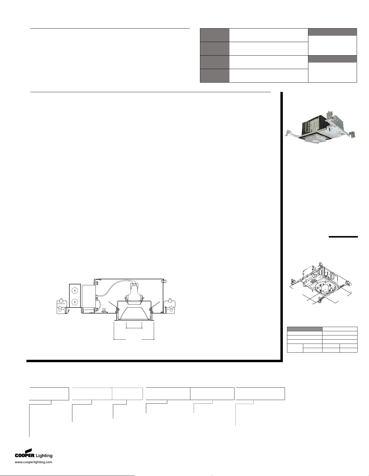
Recessed lens downlight luminaire with 2-1/4 inch square pinhole aperture
utilizing a MR16 GX10 ceramic metal halide lamp. Modular platform can be
reconfigured from below the ceiling to accept a broad range of lamp
modules and optical elements. Platform is suitable for shallow plenum
commercial construction. Insulation must be kept 3" from top and sides of
housing. Platform + module + element combination supports various lamp
beam spreads for desired optical distribution with excellent light control and
low aperture brightness.
Frame
Galvanized steel plaster frame with
integral bar hanger receivers. Set-
screws provide positive horizontal
locking.
Collar
Matte black steel collar adjusts
vertically for 1/2" - 1" thick ceilings
and can be rotated +/- 7.5° thru the
aperture. Integral gun sights
facilitate the use of guide strings or
laser lines. Shipped with a paint
overspray protector installed in the
collar.
Lamp Module
Installed or removed thru the
aperture or from the top and
allows lamp orientation at 0°, 90°,
180° and 270° positions.
Housing
Steel housing painted matte black
for a visually dark interior. Remo-
vable hinged top allows for top
access. All fasteners are captive.
Gaskets
Closed cell gaskets achieve
restrictive airflow requirements
without additional caulking.
Bar Hangers
Captive preinstalled bar hangers
adjusts from 8-1/2" to 24" wide;
pass thru feature allows shortening
without removal. Captive nail
penetrates standard and engi-
neered lumber. Mounting flange
levels platform with ceiling.
Integral clip attaches directly to
t-bar.
Pinhole
Diecast aluminum flange with
square pinhole aperture and
integral glass lens. Lens can be
removed to facilitate painting to
match ceiling finish. Mousetrap
type springs pull flange tight to
ceiling. Light trap eliminates spill
light at edge of flange. Provided
with both straight and angle cut
parabolic shielding cone, shipped
with angle cut version installed.
Butterfly Bracket
Provides 3" of vertical adjustment
and accept 1/2" EMT, C channel or
bar hangers.
Junction Box
(7) 1/2" trade size pry outs, (3)
integral clamps for non-metallic
cable. Rated for (8) #12 thru branch
circuits. Wago® type push wire
connectors for field connections
Thermal Protector
Self-resetting thermal protector
protects against improper lamping
and direct contact with insulation.
Ballast
Universal input electronic ballast
provides full light output and rated
lamp life. Provides noise free
operation and starting. Offers
excellent line voltage regulation
resulting in increased color
stability and flicker free operation.
Lamp Capsule
Pulse rated GX10 lampholder
connects to ballast with electrical
quick connects. Accepts 1 lens,
filter, or optional lamp snoot.
Code Compliance
Thermally protected, cULus listed
for protected wet locations and
ASTM-E283 AIRTITE(tm).
P406TAT
MV4CMH20MRE
E4PINSR
20W MR16
Ceramic Metal
Halide
2-1/4 Inch Square Lens Downlight
2-1/4”
(57mm)
5-3/4”
(146mm)
ENERGY DATA Min. Starting Temp -30°C
Sound Rating Class A EMI/RFI Emissions FCC 18C
Input Frequency 50/60 Hz Power Factor > 0.99
Input Voltage 108V - 305V THD< 10%
20W
Input Power 24W Nominal
Input Current 120V 0.20A 277V0.09A
14-9/16”
(370mm)
8-1/2”
(216mm)
4-9/16”
(115mm)
5-1/8”
(130mm)
Cutout=5-3/16”
(132mm)
O R D E R I N G I N F O R M AT IO N: C o mp l e t e u ni t c on sis t s o f p l at f o r m, l a mp m o du l e an d o pt i c a l e l e me n t .
MV4CMH = Vertical
Ceramic Metal
Halide, MR16
Lamp Module
E4PINSR = 2-1/4” Square
Aperture Pinhole, Lens
Optical Element
Lamp Module
[Blank] = Self Flanged,
Matte White Flange
LSA16 = Matte black lamp
snoot accessory
L - Series Filter Media For
MR16 Lamps (see accessories spec sheet)
Flange
MV4CMH
20MRE =
20W CMH MR16
120-277V UNV
Ballast Option
Accessories
P406TCP = 4”
Square Aperture
Non-IC Chicago
Plenum Housing
Platform
P406TAT = 4”
Square Aperture
Non-IC Housing
IRIS
®
Page 2
Specifications and Dimensions subject to change without notice.
.
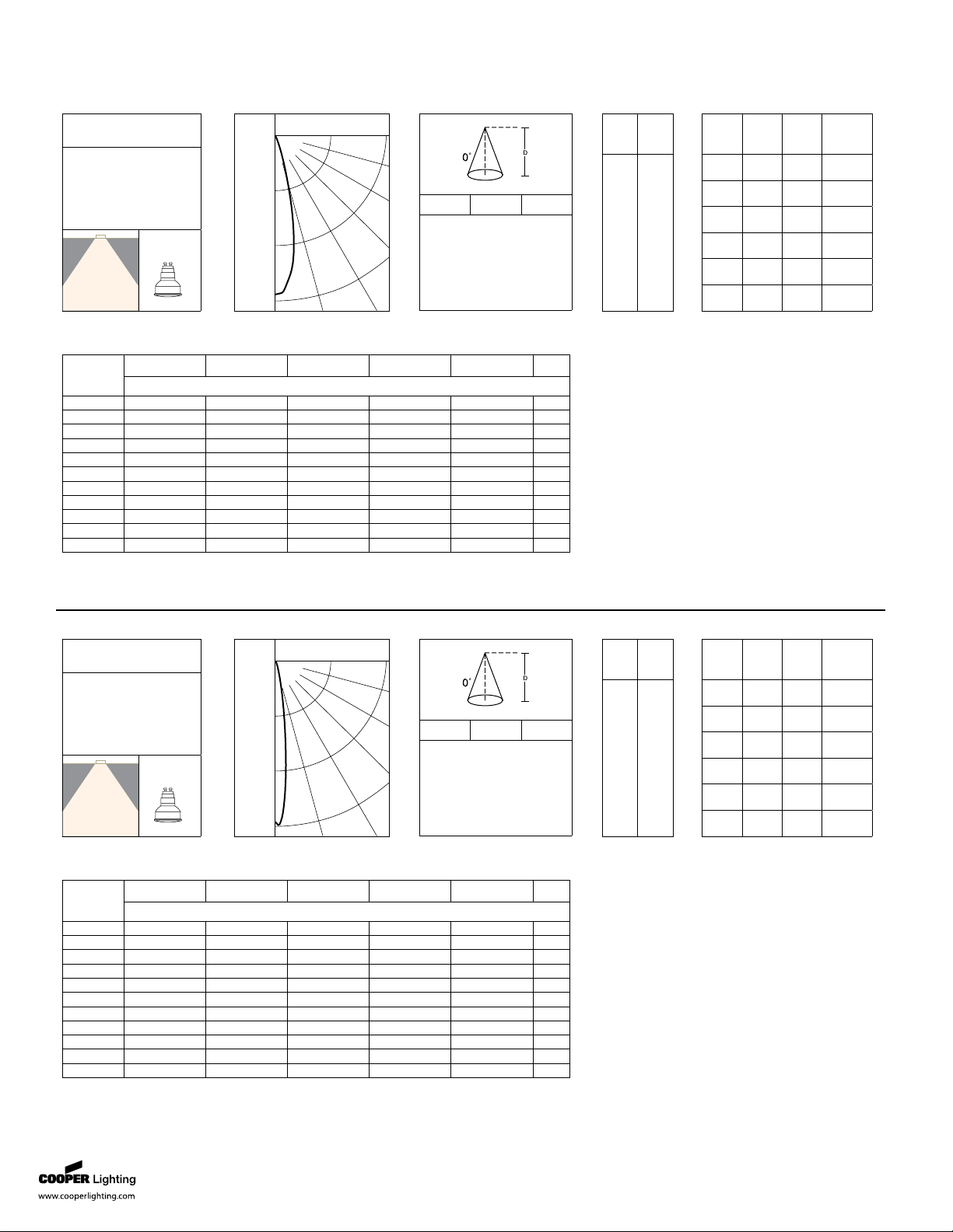
P406TAT MV4CMH20MR E4PINSR
D FC CB
8' 39 3.6'
9' 31 4.0'
10' 25 4.4'
12.5' 16 5.6'
15' 11 6.7'
Vertical
Angle
CD
90
85
75
65
55
45
35
25
15
5
0
0
1
1
1
1
1
21
110
864
2302
2488
Zone Lumens% Lamp% Luminaire
0- 30 510 51 96.4
0- 40 524 52.4 99
0- 60 526 52.6 99.4
0- 90 529 52.9 10 0
90-180 0 0 0
0-180 529 52.9 10 0
Spacing Criterion = .4
Efficiency = 52.9%
Test No. P11075
Platform = P4
Element = E4PINSR
Lumens = 1000
Lamp = CDM20/MR16/
FL25
20W
CMH MR16
Downlight
45°
30°15°0°
60°
75°
90°
850
1700
2550
Ceiling
Wall %
RCR
70 50 30 10 70 50 30 10 50 30 10 50 30 10 50 30 10 0
Zonal cavity method -- floor reflectance = 20%
0 63 63 63 63 62 62 62 62 59 59 59 56 56 56 54 54 54 53
1 61 60 59 58 60 59 58 57 57 56 55 55 54 54 53 52 52 51
2 59 57 56 54 58 56 55 54 55 54 53 53 52 51 52 51 50 50
3 57 55 53 52 56 54 53 51 53 52 50 52 51 50 51 50 49 48
4 56 53 51 49 55 52 51 49 51 50 49 50 49 48 49 48 48 47
5 54 51 49 48 53 51 49 47 50 48 47 49 48 47 48 47 46 46
6 53 50 47 46 52 49 47 46 49 47 46 48 46 45 47 46 45 44
7 51 48 46 45 51 48 46 44 47 46 44 47 45 44 46 45 44 43
8 50 47 45 43 50 47 45 43 46 44 43 46 44 43 45 44 43 42
9 49 46 44 42 48 45 43 42 45 43 42 45 43 42 44 43 42 41
10 48 44 42 41 47 44 42 41 44 42 41 44 42 41 43 42 41 40
Photometric Results Candlepower Distribution
Coefficients of Utilization
Cone of Light Zonal Lumens SummaryCandelas
D FC CB
8' 96 2.2'
9' 76 2.5'
10' 62 2.8'
13' 36 3.6'
16' 24 4.4'
Vertical
Angle
CD
90
85
75
65
55
45
35
25
15
5
0
0
1
1
1
1
1
22
61
630
4678
6168
Zone Lumens% Lamp% Luminaire
0-30 573 57.3 97
0-40 587 58.7 99.2
0-60 589 58.9 99.5
0-90 591 59.1 10 0
90-180 0 0 0
0-180 591 59.1 10 0
Spacing Criterion = .3
Efficiency = 59.1%
Test No. P10975
Platform = P4
Element = E4PINSR
Lumens = 1000
Lamp = CMH20/MR16/
G10/SP 12°
20W
CMH MR16
Downlight
45°
30°15°0°
60°
75°
90°
2100
4200
6300
Ceiling
Wall %
RCR
70 50 30 10 70 50 30 10 50 30 10 50 30 10 50 30 10 0
Zonal cavity method -- floor reflectance = 20%
0 70 70 70 70 69 69 69 69 66 66 66 63 63 63 60 60 60 59
1 68 67 66 65 67 66 65 64 64 63 62 61 61 60 59 59 59 58
2 66 65 63 62 65 64 62 61 62 61 60 60 59 59 59 58 57 57
3 65 63 61 59 64 62 60 59 60 59 58 59 58 57 58 57 56 56
4 63 61 59 57 63 60 58 57 59 58 56 58 57 56 57 56 55 55
5 62 59 57 56 61 59 57 55 58 56 55 57 56 55 56 55 54 54
6 61 58 56 54 60 57 56 54 57 55 54 56 55 54 55 54 53 53
7 60 57 55 53 59 56 54 53 56 54 53 55 54 53 55 53 52 52
8 59 55 53 52 58 55 53 52 55 53 52 54 53 52 54 52 52 51
9 58 54 53 51 57 54 52 51 54 52 51 53 52 51 53 52 51 50
10 57 53 52 50 56 53 52 50 53 51 50 53 51 50 52 51 50 50
Photometric Results Candlepower Distribution
Coefficients of Utilization
Cone of Light Zonal Lumens SummaryCandelas
IRiS • Customer First Center • 1121 Highway 74 South • Peachtree City, GA 30269 • TEL 770.486.4800 • FAX 770.486.4801
02/28/2008 9:02:28 AM
ADI070195
 Loading...