

Page 1

iris-GmbH | Ostendstrasse 1 – 14 | 12459 Berlin | Germany Rev. 1.2 | 2016-02
www.irisgmbh.de Subject to alterations!
Automatic passenger counting
IRMA – Infrared Motion Analyser
5
th
generation
IRMA MATRIX
Start on the PC via Ethernet
Operating Instructions
For the service software variants of
IRMA-MATRIX-Configuration
IRMA-MATRIX-Visualization
IRMA-TestRide-IRMA MATRIX
Page 2

2/15
Starting IRMA MATRIX on the PC via Ethernet
released
Rev. 1.2
2016-02
Document information
Title of document: Starting IRMA MATRIX on the PC via Ethernet
Revision: 1.2
Edition (YYYY-MM): 2016-02
Type of document: Customer documentation
Status: released
Document history
Rev.
Date
Name
Comments/modifications
1.2
24.02.2016
VEGI
First edition
1.2
29.02.2016
VEGI
Page 6: changed "IP address" - >"IP address range"
Validity
Sensors and connectors covered by this document:
Product
Component
Product designation
Description
IRMA MATRIX
DIST500-A
DIST500.7-A07.OC
Sensor of the surface mount
version
IRMA MATRIX
DIST500-F
DIST500.7-F07.OC
Sensor of the flush mount
version
sCON-S
sCON-S-CAN-ETH-23-Kq-x-y
Standard connector with
interfaces CAN, Ethernet
for MATRIX sensors
sCON-S
sCON-S-ETH-22-Kq-x-y
Standard connector with
interfaces CAN, Ethernet
for MATRIX sensors
Page 3

3/15
Starting IRMA MATRIX on the PC via Ethernet
Rev. 1.2
2016-02
Table of contents
1 General .......................................................................................................................... 4
1.1 Symbols / abbreviations used .................................................................................................... 4
1.2 Brief description ............................................................................................................................. 4
2 Preparation ................................................................................................................... 5
2.1 Equipment required ...................................................................................................................... 5
2.2 Overview of the necessary steps of work ............................................................................... 6
3 Checking the settings in the network architecture ..................................................... 6
4 Making the IP settings (PC) .......................................................................................... 6
4.1 Changing (setting) the IP address of your PC network adapter ........................................ 7
4.2 Setting as a second IP address ................................................................................................... 8
5 Switching off the WLAN ............................................................................................. 10
6 Connecting the sensor ................................................................................................ 11
6.1 PC connection with a standard connector of the type sCON-S-CAN-ETH-23-Kq-x-y11
6.2 PC connection with a standard connector of the sCON-S-ETH-22-Kq-x-y type ........ 12
7 Starting the service software ..................................................................................... 13
7.1 Before the first run of the service software program ....................................................... 13
7.2 Important at each start of the software............................................................................... 14
7.2.1 DIST500-Configuration_3.3.1.142 (or higher) .................................................................... 14
7.2.2 DIST500-Visualization_4.2.0.112 (or higher) ...................................................................... 14
7.2.3 IRMA TestRide 2.8.1.37 (or higher) ......................................................................................... 14
8 Restoring the initial state at the PC ........................................................................... 15
Table of illustrations
Figure 1: Select Internet protocol type 4(TCP/IPv4), right: Enter IP address ........................ 7
Figure 2: How to enter the extended PCP/IP settings ................................................................ 8
Figure 3: Entering the IP address for IRMA MATRIX as a second entry .................................. 9
Figure 4: PC connection with sCON-S-CAN-ETH-23-Kq-x-y standard ................................. 11
Figure 5: PC connection with sCON-S-ETH-22-Kq-x-y ............................................................. 12
Figure 7: Entry in the "Properties" window of a service software tool ............................... 13
Page 4

4/15
Starting IRMA MATRIX on the PC via Ethernet
released
Rev. 1.2
2016-02
1 General
1.1 Symbols / abbreviations used
"Please note!"
"Information"
"Instructions"
"Download"
"See Annex"
"See document on our website"
M12CAN-CON-03
iris product designation / name of an IRMA MATRIX component
sCON
Connector for IRMA MATRIX sensors
Connector (f)
Female connector
Connector (m)
Male connector
x, y Variable cable executions or variable cable lengths
XX or Kq
Cable available in 2 different cable qualities
"Advanced“
Name of a window or button
1.2 Brief description
These instructions describe the steps required for connecting an IRMA MATRIX sensor to
any PC. Afterwards, a suitable software program enables for example the check of the
condition on delivery, configuration of the sensor properties, updating of the firmware or
viewing of the sensor graphic data. Communication between the sensor and the PC is
effected via Ethernet.
Page 5

5/15
Starting IRMA MATRIX on the PC via Ethernet
released
Rev. 1.2
2016-02
2 Preparation
2.1 Equipment required
• PC with Windows XP operating system or higher
• IRMA-MATRIX sensor(s)
• Service software programs for IRMA MATRIX sensors
Can be downloaded from www.irisgmbh.de: in the following variants:
• DIST500-Configuration (for sensor configuration)
• DIST500-Visualization (visualizes the measuring characteristics of a sensor)
• IRMA TestRide, IRMA MATRIX (for signal recording on test rides)
What is required for connecting an IRMA MATRIX sensor to the PC:
1. 24 V power block M12 with M12 connecting cable: M12 connector (f, 5 poles, A coded).
The power block is available as an accessory.
2. The following sensor-connector combinations can be used for servicing IRMA MATRIX
sensors via Ethernet:
• Type sCON-S-CAN-ETH-23-Kq-x-y with interfaces CAN, Ethernet for MATRIX
sensors (see also Figure 4, page 11).
• Type sCON-S-ETH-22-Kq-x-y with Ethernet interface for MATRIX sensors (see
Figure 5, p. 12)
3. Commercial Ethernet switch with several RJ45 or M12 slots.
4. M12/RJ45 adapter cable KQ-M12CAT5-RJ45-01-xm (accessory)
M12 connector (male, 4 poles, D coded) to RJ45 connector (male) for PC connection
x = 2 m/10 m.
All cables and components used here are described in detail in the "M12 components for
Ethernet installations" catalogue.
Page 6

6/15
Starting IRMA MATRIX on the PC via Ethernet
released
Rev. 1.2
2016-02
2.2 Overview of the necessary steps of work
1. Downloading the software to your PC
2. Checking the settings in the network architecture
3. Setting the IP address for your PC
4. Deactivating WLAN
5. Connecting the sensor(s)
6. Performing the servicing work on the sensor
7. Restoring the original settings of the PC network adapter
3 Checking the settings in the network architecture
The following UDP ports must be released for the network architecture:
34952
34953
34954
Otherwise, there will be no connection!
4 Making the IP settings (PC)
The sensor has its own IP address which can be configured. In condition as delivered it
starts as follows: (10.x.x.x). However, it can deviate due to customer-specific configuration
requests.
For the PC to recognize the sensor and communicate with it, the PC must use the same IP
address range. Therefore the IP address of the PC network adapter must be changed or else
an additional IP address range entered. For this purpose any address from the IP address
range of (10.0.0.x) with x = 11 ... 249 can be used.
The system does not support DHCP.
Page 7

7/15
Starting IRMA MATRIX on the PC via Ethernet
released
Rev. 1.2
2016-02
4.1 Changing (setting) the IP address of your PC network
adapter
Select or open the following windows one after the other:
For
Windows XP:
1.a
"Control Panel"\"Network Settings"
\"Local Area Connection"\"Properties"\"Internet Protocol (TCP/IP)"
\"Properties"
For
Windows 7/8:
1.b
"Control Panel" "Network and Internet1" "Network and Sharing Center"
\"Local Area Connection" (for Windows 8: Ethernet connection)
In the "Local Area Connection Status" window click on the button "Properties".
In the "Local Area Connection Status properties" window select the Internet
Protocol Version 4 (TCP/IPv4) by clicking on it (see Figure 1 to the left) and click
on the "Properties" button.
For
Windows
XP, 7, 8
2.
If in the "Internet Protocol Version 4 (TCP/Pv4) Properties" window the setting
"Obtain an IP address automatically" is activated, the setting must be changed to
"Use the following IP Address" (see Figure 1 on the right).
If the setting "Use the following IP Address" has been activated, the IP address
for the sensors can be set as a second IP setting (see section 4.2 on page 8).
Figure 1: Select Internet protocol type 4(TCP/IPv4), right: Enter IP address
1
For "Network and Internet", "All Control Panel Items" can also be the right choice.
Page 8

8/15
Starting IRMA MATRIX on the PC via Ethernet
released
Rev. 1.2
2016-02
3. Then the items of the IP address can be activated for entry by a mouse-click.
The following entries are possible:
IP address: 10.0.0.x with x = 11 – 249
The first 10 IP addresses are mostly reserved for other services. Please do not use them.
We are using x = 55 for our example (see Figure 1 on the right).
4. For our example please enter:
"IP address:" | 10 | 0 | 0 | 55 |
"Subnetwork mask:" | 255 | 0 | 0 | 0 |
Please do not make any entries for the "Standard gateway" or DNS server.
4.2 Setting as a second IP address
If the setting "Obtain an IP address automatically" has been activated (see Figure 2 on the
right), the IP address for the sensors can also be used as a second IP setting:
• For this purpose press the "Advanced..." button. (see Figure 2 on the left), the "Advanced
TCP/IP Settings" button opens (see Figure 2 on the right).
Figure 2: How to enter the extended PCP/IP settings
Page 9

9/15
Starting IRMA MATRIX on the PC via Ethernet
released
Rev. 1.2
2016-02
• On the "IP settings" tab in the "IP address" area click on the "Add..." button. The input
mask "TCP/IP Address" opens, see Figure 3 on the left.
• For our example please enter:
"IP address:" | 10 | 0 | 0 | 55 |
"Subnet mask:" | 255 | 0 | 0 | 0 |
• Conclude the entry of the IP address by clicking "Add", it will appear as the second entry
(see Figure 2 on the right).
Figure 3: Entering the IP address for IRMA MATRIX as a second entry
Page 10

10/15
Starting IRMA MATRIX on the PC via Ethernet
released
Rev. 1.2
2016-02
5 Switching off the WLAN
In order to prevent communication problems, absolutely switch off the WLAN!
• If available, please switch off the WLAN hardware switch on the PC
or
• deactivate the WLAN symbol in the status bar or
• deactivate WLAN via the PC operating system via the path
"Control Panel" "Network and Internet 2" "Manage Wireless Network"
On conclusion of the work with the sensor the original setting must be restored.
2
For "Network and Internet", "All Control Panel Items" can also be the right choice.
Page 11

11/15
Starting IRMA MATRIX on the PC via Ethernet
released
Rev. 1.2
2016-02
6 Connecting the sensor
The sensor and computer are connected via the Ethernet. The connection is made using an
Ethernet switch.
6.1 PC connection with a standard connector of the type
sCON-S-CAN-ETH-23-Kq-x-y
1. Connect the IRMA MATRIX sensor with the connector. See Figure 4.
2. Connect the Ethernet interface of the sensor (M12 female connector, 4 poles) to the
M12 connector (male, 4 poles), using an adapter cable (see Figure 4 with item (4) or
(5)).
3. Connect the adapter cable to the switch.
4. Connect the switch with the PC (see Figure 4 with item (4) or (6)).
5. Connect the CAN interface of the sensor (M12 male connector type CAN to the M12
female connector (type CAN) of the Power block (item 3).
6. The final step is to connect the power block to power supply!
1 IRMA MATRIX sensor (flush mount or surface mount version)
2 Standard connector with interfaces CAN and Ethernet
of type sCON-S-CAN-ETH-23-Kq-x-y
3 Power block 24 V-M12
4 Adapter cable for connection to the RJ45-switch
KQ-M12CAT5-RJ45-01-xm
5 M12 Ethernet system cable for connection to the M12-switch
K-M12CAT5-XX-xm
6 Commercial patch cable with 2x RJ45 connectors
M12 male connectors are marked by blue contours
M12 female connectors are filled in in red
...
M12 connector (m, f) of type CAN are 5 pole and A coded.
M12 connector (m, f) of type ETH are 4 pole and D coded
Figure 4: PC connection with sCON-S-CAN-ETH-23-Kq-x-y standard
Page 12
12/15
Starting IRMA MATRIX on the PC via Ethernet
released
Rev. 1.2
2016-02
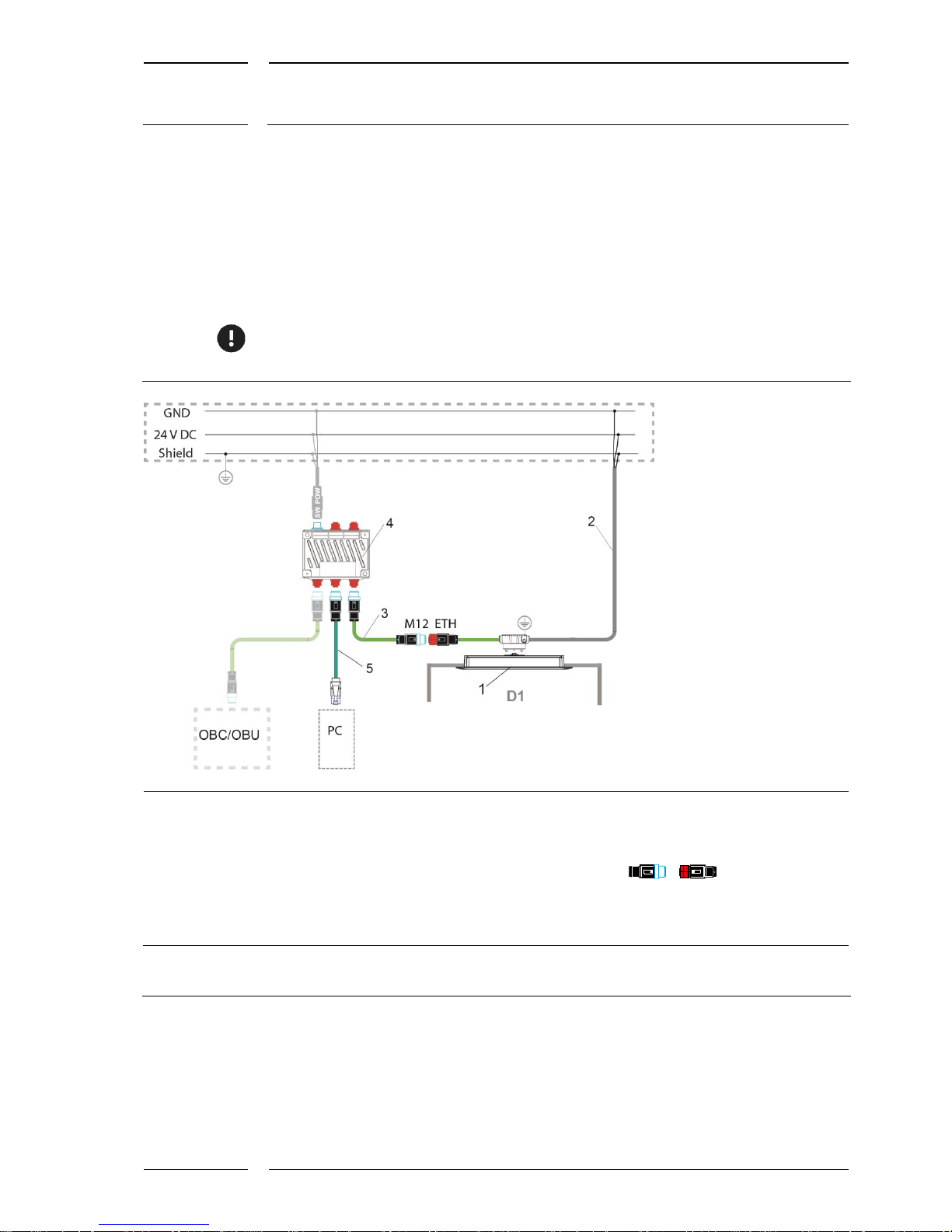
6.2 PC connection with a standard connector of the
sCON-S-ETH-22-Kq-x-y type
This sCON is installed in vehicles fitted with a switch. On installation the sensor power
supply is connected as specified in the installation instructions. Connect the PC to the
switch using suitable cables, see Figure 5, item 5.
For service work, you first need to ascertain the connector type of the switch. An adapter
can be necessary. The most common types are e.g.: SUB-D9, RJ45, M12 (D coded).
1 IRMA MATRIX sensor DIST500-A/DIST500-F
(surface mount or flush mount version)
2 Standard connector with Ethernet interface:
sCON-S-ETH-22-Kq-x-y
3 M12 system cable type ETH, K-M12CAT5-XX-x
4 Switch e.g. Switch-M12-5Port-eCon
5 M12-RJ45 adapter cable type ETH
KQ-M12CAT5-RJ45-01-xm
OBC/OBU:
On-Board Computer/On-Board Unit
D1 Door 1
M12 male connectors are marked by blue
contours
M12 female connectors are filled in in red
M12 connector (m, f) of type ETH
are 4 pole and D coded.
Figure 5: PC connection with sCON-S-ETH-22-Kq-x-y
Page 13

13/15
Starting IRMA MATRIX on the PC via Ethernet
released
Rev. 1.2
2016-02
7 Starting the service software
7.1 Before the first run of the service software program
In order to prevent communication problems, the communication path is determined for
all service software variants. Before the first run of a service software tool please proceed
as follows:
1. Mark the program icon on the desktop, right-click and select "Properties". The
"Properties ..." windows opens.
2. Click into the input window "Target", see Figure 6.
3. Directly behind "DIST500-Configuration.exe" enter the following string:
[1 x space]-ipaddr=10.0.0.55
The characters "10.0.0.55" must correspond to the address which had before been
entered as the IP address for the PC (see section 4.1 on page 7).
4. Click "OK" to save the entry.
Figure 6: Entry in the "Properties" window of a service software tool
Page 14

14/15
Starting IRMA MATRIX on the PC via Ethernet
released
Rev. 1.2
2016-02
7.2 Important at each start of the software
Always switch the sensor on first via the switch on the PC. Then activate the power supply.
In some cases a sensor RESET may be necessary. For this purpose disconnect the sensor
from its power supply for a period of approx. 3 s. Then start the service software tool.
7.2.1 DIST500-Configuration_3.3.1.142 (or higher)
This software program is a tool enabling the entry of important configuration parameters
via the PC. The most important parameter is the installation height. After sensor mounting
it must be set to the actual installation height of the sensor.
Please refer to the "IRMA-MATRIX-Configuration-Tool" operating instructions for more
detailed information.
7.2.2 DIST500-Visualization_4.2.0.112 (or higher)
This software program is a tool for the representation of the ongoing counting process and
the monitoring range of a sensor. Simultaneously the height measurement of the sensor in
a two-dimensional range is shown in real time. The representation of different heights by
different colors yields an image appearing to be three-dimensional of the movement of any
moving object underneath the sensor.
Please refer to the "IRMA-MATRIX-Visualization-Tool" operating instructions for more
detailed information.
7.2.3 IRMA TestRide 2.8.1.37 (or higher)
This software program enables the determination of the counting accuracy at several
doors simultaneously by comparing the sensors' counting results with the counting results
obtained manually at the same time (e.g. on test rides).
Please refer to the "IRMA-TestRide" operating instructions for more detailed information.
Page 15

15/15
Starting IRMA MATRIX on the PC via Ethernet
released
Rev. 1.2
2016-02
8 Restoring the initial state at the PC
On conclusion of the work with the sensor on the PC the modified settings for the network
adapter must be reset. This can be omitted only if the IP address of the sensors was made
as a second IP entry.
In order to prevent unnecessary PC reboots, it has proven successful to restore the previous
settings of the network adapter even before the PC-sensor connection is interrupted. For
this purpose observe the instructions in section 4.1, page 7, up to item 3. Here the setting
"Get IP address automatically" must be activated again.
 Loading...