

Page 1

®
iQ
200 Sprint ™
Service Manual
Iris Diagnostics, a Division of Iris International, Inc.
Page 2

Table of Contents
1 - Introduction
Intended Use ...................................................................................................... 1-2
How to use this Manual ......................................................................................1-2
Precautions and Warnings .................................................................................1-4
Notes .................................................................................................................. 1-4
Cautions .............................................................................................................1-4
Warnings ............................................................................................................1-4
Biological Warning..............................................................................................1-4
Warranty.............................................................................................................1-5
Limitation of Liability........................................................................................... 1-6
Use of Third Party Computer Products ..............................................................1-6
Iris Diagnostics Contact Information...................................................................1-7
2 - Installation Procedures
Installation Requirements...................................................................................2-2
Space Requirements..........................................................................................2-2
Workstation ........................................................................................................2-2
Location.............................................................................................................. 2-2
Requirements .....................................................................................................2-2
Installation ..........................................................................................................2-2
Shipping Cartons................................................................................................2-3
Instrument Carton...............................................................................................2-3
Starter Kit A Carton ............................................................................................ 2-4
Starter Kit B Carton (needs refrigeration)...........................................................2-4
Optional .............................................................................................................. 2-4
Installation ..........................................................................................................2-5
Precautions ........................................................................................................2-5
Connecting the Sampler.....................................................................................2-6
Adjust the Height of the Analyzer .......................................................................2-6
Adjust Sampler ...................................................................................................2-7
Installing the Lamina Container..........................................................................2-7
Connecting the Drain Tubing..............................................................................2-7
Computer Connections.......................................................................................2-8
iQ200 Rear Panel SIC Connection Configurations ............................................2-9
iQ200 / AX-4280 Connection Bridge Instructions............................................. 2-10
Optional Load/Unload Station Installation ........................................................ 2-15
Load Station - iQ200 Connection ..................................................................... 2-15
Load Station - AX-4280 Connection.................................................................2-17
Unload Station..................................................................................................2-19
Startup..............................................................................................................2-21
Run Focus ........................................................................................................ 2-22
Iris Diagnostics, a Division of Iris International, Inc.
®
iQ
200 Sprint™ (2G) Automated Urine Microscopy Analyzer Service Manual 300-4949 Rev A 01/2005 1
Page 3

Table of Contents
Run Calibration Rack .......................................................................................2-22
Run Control Rack .............................................................................................2-22
Verify Load/Unload and Bridge Connections ...................................................2-22
Preparation for Starting Operation ...................................................................2-22
Perform Setup .................................................................................................. 2-22
3 – Components
Sample Transport Mechanism ...........................................................................3-3
Sampler # 700-3006...........................................................................................3-3
Specimen Tube Detector # 700-3725 ................................................................3-4
Barcode Reader # 700-3315 ..............................................................................3-5
Specimen Presentation Assembly # 700-3700 ..................................................3-6
Crash Detect Function........................................................................................3-6
Waste/Rinse Well # 700-3830............................................................................3-7
Diaphragm Pumps..............................................................................................3-8
Air Pump # 700-3877 .........................................................................................3-8
Waste Pump # 700-3809....................................................................................3-8
Rinse Pump # 700-3874.....................................................................................3-8
Fill Pump # 700-3874 ......................................................................................... 3-8
Peristaltic Pumps # 700-3820 ..........................................................................3-10
Cannula Pump..................................................................................................3-10
Lamina Pump ................................................................................................... 3-10
Evacuation Pump ............................................................................................. 3-10
Pump Cover Closed and Cassette-In-Place Detection ....................................3-10
Lamina Tank # 700-3784 .................................................................................3-12
Air Tank # 700-3802.........................................................................................3-13
Valves...............................................................................................................3-14
Solenoid Valves................................................................................................3-14
Drain Valve # 700-3844....................................................................................3-14
Evacuation Bypass Valve # 700-3843..............................................................3-14
Lamina Bypass Valve # 700-3842....................................................................3-14
Cannula Bypass Valve # 700-3881 ..................................................................3-14
Pipettor Bypass Valve # 700-3880 ...................................................................3-14
Air Valves ......................................................................................................... 3-15
Air Mix Valve # 700-3887 .................................................................................3-15
Air Charge Valve # 700-3888 ...........................................................................3-15
Optical Bench Assembly #700-3500 ................................................................ 3-16
Flow Cell # 525-3077 .......................................................................................3-17
Strobe Light # 065-0059...................................................................................3-17
CCD Camera # 700-3565.................................................................................3-17
20 x Objective # 220-3009 ...............................................................................3-17
Auto Focus System # 700-3505 .......................................................................3-17
Power System Assembly # 230-3000 ..............................................................3-18
Iris Diagnostics, a Division of Iris International, Inc.
®
iQ
200 Sprint™ (2G) Automated Urine Microscopy Analyzer Service Manual 300-4949 Rev A 01/2005 2
Page 4

Table of Contents
Cooling Fans # 700-3892 & 700-3412 .............................................................3-18
Fuses and Visible LEDs ...................................................................................3-18
Backplane Fuses and LEDs ............................................................................. 3-19
PCBA Summary ...............................................................................................3-21
Cardcage..........................................................................................................3-22
High Level Control Board (HLCB), # 101-5000 ................................................3-22
Motor/Scanner Control Board (MSCB), # 101-5001.........................................3-22
DC Valve Board (DCVB), # 101-5043 ..............................................................3-22
Stepper/Scanner/Motor Board (SSMB), # 101-5007........................................3-23
Backplane # 101-5003 .....................................................................................3-23
Signal Interface Concentrators (SICs)..............................................................3-24
Power SIC # 101-5020 .....................................................................................3-24
Pump SIC #101-5020.......................................................................................3-25
FSV SIC # 101-5045 ........................................................................................ 3-25
SPA SIC # 101-5004 ........................................................................................3-27
SPA SIC Visible LEDs......................................................................................3-27
SPA SIC Push-Button Switches .......................................................................3-27
OBA SIC #101-5053.........................................................................................3-28
Do-All SIC # 101-5046 .....................................................................................3-29
Rear Panel SIC # 101-5030 ............................................................................. 3-30
STM SIC # 101-5014........................................................................................3-30
Other PCBAs....................................................................................................3-30
ESN Board # 101-5049 .................................................................................... 3-30
Lamina ESN # 101-5048 ..................................................................................3-30
FITD PCBA # 101-5041 ...................................................................................3-30
SM Status Board PCBA # 101-5032 ................................................................3-31
STD PCBA # 101-5034 .................................................................................... 3-31
Pressure Transducer Board #101-5016 ...........................................................3-31
SPA Optical Board # 101-5052 ........................................................................ 3-31
LED Visual Indicators ....................................................................................... 3-31
4 – Adjustments
Accessing the Service Screen............................................................................4-3
Calibration Table ................................................................................................ 4-4
Calibration Auto-Sets .........................................................................................4-4
Sampler Calibration............................................................................................4-6
Material required ................................................................................................4-6
Procedure...........................................................................................................4-6
Specimen Tube Detector Alignment...................................................................4-7
Material required ................................................................................................4-7
Procedure...........................................................................................................4-7
Specimen Tube Detector Calibration .................................................................4-8
Material required ................................................................................................4-8
Iris Diagnostics, a Division of Iris International, Inc.
®
iQ
200 Sprint™ (2G) Automated Urine Microscopy Analyzer Service Manual 300-4949 Rev A 01/2005 3
Page 5

Table of Contents
Procedure...........................................................................................................4-8
STD Verification Procedure................................................................................4-9
Specimen Presentation Assembly (SPA) and Waste/Rinse Well Calibration ..4-10
Material required ..............................................................................................4-10
Procedure.........................................................................................................4-10
Waste Well Positioning.....................................................................................4-10
Test Tube Centering Position...........................................................................4-11
Test Tube Depth Positioning ............................................................................ 4-11
Waste Well Depth Positioning ..........................................................................4-12
Lamina Consumption Adjustment ....................................................................4-12
Air Pressure Calibration ...................................................................................4-13
Material required ..............................................................................................4-13
Procedure.........................................................................................................4-13
Barcode Reader Alignment .............................................................................. 4-14
Material Required .............................................................................................4-14
Procedure.........................................................................................................4-14
Prepare Barcode Reader Connections ............................................................4-14
Load the Alignment Tool ..................................................................................4-15
Perform barcode alignment ..............................................................................4-15
Validation..........................................................................................................4-18
Collimation........................................................................................................4-19
What is a Collimation?......................................................................................4-19
Condenser Alignment.......................................................................................4-19
Run Auto Focus................................................................................................4-20
Flow Cell Replacement ....................................................................................4-21
Flow Cell Removal ...........................................................................................4-21
Flow Cell Installation ........................................................................................4-21
Flow Cell Lateral Adjustment............................................................................4-22
Flow Cell Tilt Adjustment..................................................................................4-23
5 - Service Application Software
Accessing the Service Screen............................................................................5-3
Startup................................................................................................................5-3
Establishing Link ................................................................................................5-4
Live Operation ....................................................................................................5-5
Tree View Pane..................................................................................................5-5
Commands .........................................................................................................5-6
Preset Moves .....................................................................................................5-6
Sensors ..............................................................................................................5-6
Register 0x0A.....................................................................................................5-7
Calibration Table ................................................................................................ 5-7
Calibration Auto-Sets .........................................................................................5-7
Sequences .........................................................................................................5-7
Iris Diagnostics, a Division of Iris International, Inc.
®
iQ
200 Sprint™ (2G) Automated Urine Microscopy Analyzer Service Manual 300-4949 Rev A 01/2005 4
Page 6

Table of Contents
Fluid Schematic Pane ........................................................................................5-8
Diaphragm Pumps..............................................................................................5-8
Peristaltic Pumps................................................................................................5-8
3-Way Valves ..................................................................................................... 5-9
2-Way Valves ..................................................................................................... 5-9
Motors ................................................................................................................5-9
Tube Connectors..............................................................................................5-10
Other Regions of Interest ................................................................................. 5-10
Menu Bar..........................................................................................................5-10
File Menu..........................................................................................................5-10
View Event Log ................................................................................................5-10
Show Versions Report......................................................................................5-11
Exit ...................................................................................................................5-11
Edit Menu ......................................................................................................... 5-11
View Menu........................................................................................................5-11
Toolbar .............................................................................................................5-11
Status Bar.........................................................................................................5-12
Polling...............................................................................................................5-12
Video ................................................................................................................5-12
Record Video Statistics .................................................................................... 5-12
Terminal ...........................................................................................................5-12
Jog Menu..........................................................................................................5-13
Status Bar.........................................................................................................5-13
Current Message Status...................................................................................5-13
Link Status........................................................................................................5-14
“Starting ASTM”................................................................................................5-14
“Establishing link (may take a minute)” ............................................................5-14
“Could not establish link”..................................................................................5-15
Troubleshooting Failure to Establish Link ........................................................5-15
“Connection established”..................................................................................5-15
“Sending initialization messages”..................................................................... 5-16
“Sending initial query messages” ..................................................................... 5-16
“Sending query messages” ..............................................................................5-16
“Idle” .................................................................................................................5-16
Caps Lock Status .............................................................................................5-16
Num Lock Status ..............................................................................................5-16
Scroll Lock Status.............................................................................................5-16
Sequences & Sensor Identifications for Troubleshooting.................................5-17
Master (Master Controller) ...............................................................................5-17
Sequences .......................................................................................................5-17
Level sensors ...................................................................................................5-17
SPA .................................................................................................................. 5-17
Pumps/Evacuation pump/Sensors ...................................................................5-18
STM..................................................................................................................5-18
Iris Diagnostics, a Division of Iris International, Inc.
®
iQ
200 Sprint™ (2G) Automated Urine Microscopy Analyzer Service Manual 300-4949 Rev A 01/2005 5
Page 7

Table of Contents
Sensors ............................................................................................................5-18
FBA ..................................................................................................................5-18
Pumps/Sheath pump/Sensors..........................................................................5-18
Pumps/Cannula pump/Sensors........................................................................5-18
Program Operation...........................................................................................5-19
Frequently Asked Questions (FAQ) .................................................................5-19
Why Does a Sensor Display the Wrong Value?...............................................5-19
Which Controller Does Component X (Pump, Valve, etc.) Belong To? ...........5-19
What Are the Communication Addresses of the Major System Components? 5-20
What Should I Do If the Service Application Appears to Hang?.......................5-20
Service Tree .....................................................................................................5-21
Master ..............................................................................................................5-21
SPA Motors ......................................................................................................5-22
SPA Pumps and Valves ...................................................................................5-23
FBA Pumps and Sequences ............................................................................5-25
STM Motors 1...................................................................................................5-26
STM Motors 2, Sensors, Calibration Table and Sequences ............................5-27
OBA..................................................................................................................5-28
Versions 1 ........................................................................................................5-29
Versions 2 ........................................................................................................5-30
6 - Troubleshooting
Bypassing Error Condition..................................................................................6-2
Decoding the Valves field in Valve Error Reports ..............................................6-2
Iris Diagnostics Contact Information...................................................................6-2
Troubleshooting Guide ....................................................................................... 6-3
System locked up ...............................................................................................6-3
Autofocus failed.................................................................................................. 6-3
IQ 200 fails to go to Standby .............................................................................. 6-4
ID errors .............................................................................................................6-4
Illumination/Sequential errors.............................................................................6-5
Valve failure to open or close .............................................................................6-5
System does not go into Standby mode.............................................................6-5
Samples take more than 60 secs to process and complete...............................6-5
Positive control failure ........................................................................................6-5
Calibration rack failed......................................................................................... 6-5
Non uniform flow in Runfile ................................................................................6-6
Inconsistent cell count from run to run in Runfile ...............................................6-6
SP-FLI (spatial flow index) is high in all Runfiles................................................6-6
SP-KSP are high in all Runfiles..........................................................................6-6
Bubbles are present in fluid system ...................................................................6-6
Waste well overflow............................................................................................6-6
Event Log Error Messages.................................................................................6-7
Iris Diagnostics, a Division of Iris International, Inc.
®
iQ
200 Sprint™ (2G) Automated Urine Microscopy Analyzer Service Manual 300-4949 Rev A 01/2005 6
Page 8

Table of Contents
7 - Electronics
Electronics..........................................................................................................7-2
General Functions .............................................................................................. 7-2
Cabling Diagram Overview.................................................................................7-3
View of Backplane inside Cardcage...................................................................7-4
Rear view of Backplane -- Fuses and Connections to Internal parts of Microscopy
Module................................................................................................................7-5
Addresses and Summary ................................................................................... 7-6
Hardware Bit Assignments and Details ............................................................7-11
Hardware Assignment Cross Reference ..........................................................7-21
ESN I2C Addresses .........................................................................................7-27
8 - Schematics
998-3006 SM SMCS Assemblies Block Diagram...............................................8-3
700-3800 System Fluid Assembly......................................................................8-4
Master Controller State records .........................................................................8-5
SPA State records............................................................................................8-21
FBA State records ............................................................................................ 8-25
STM State records ...........................................................................................8-27
9 - Preventive Maintenance
Material...............................................................................................................9-2
Semi-Annual PM kit Part Number 799-3050 ......................................................9-2
Annual PM Kit Part Number 799-3051 ..............................................................9-2
Cleaning .............................................................................................................9-3
Instrument Clean Up ..........................................................................................9-3
Fluidics Clean Up ............................................................................................... 9-3
Rinse/Waste Well Clean Up ...............................................................................9-3
Air blow...............................................................................................................9-3
Computers Clean Up..........................................................................................9-3
Laser Printer.......................................................................................................9-3
Fluidics ...............................................................................................................9-4
Liquid Waste.......................................................................................................9-4
Peristaltic pump cassette replacement...............................................................9-4
Tubing replacements..........................................................................................9-4
Adjustment verification ....................................................................................... 9-5
Sampler Rack alignment .................................................................................... 9-5
Specimen Tube Detector verification .................................................................9-5
Barcode Reader alignment verification ..............................................................9-5
SPA alignment verification .................................................................................9-5
Iris Diagnostics, a Division of Iris International, Inc.
®
iQ
200 Sprint™ (2G) Automated Urine Microscopy Analyzer Service Manual 300-4949 Rev A 01/2005 7
Page 9

Table of Contents
Fluidic inspection................................................................................................9-6
Autofocus run .....................................................................................................9-6
Optical Bench Verification .................................................................................. 9-6
Replenish Consumables ....................................................................................9-6
Performance verification.....................................................................................9-7
Software ............................................................................................................. 9-7
Calibration run .................................................................................................... 9-7
Control run..........................................................................................................9-7
Documenting the Preventive Maintenance.........................................................9-7
Iris Diagnostics, a Division of Iris International, Inc.
®
iQ
200 Sprint™ (2G) Automated Urine Microscopy Analyzer Service Manual 300-4949 Rev A 01/2005 8
Page 10

1. Introduction
1
Introduction
Intended Use.................................................................................................................. 1-2
How to use this Manual..................................................................................................1-2
Precautions and Warnings ............................................................................................. 1-4
Notes ..........................................................................................................................1-4
Cautions .....................................................................................................................1-4
Warnings ....................................................................................................................1-4
Biological Warning...................................................................................................... 1-4
Warranty.........................................................................................................................1-5
Limitation of Liability.......................................................................................................1-6
Use of Third Party Computer Products ..........................................................................1-6
Iris Diagnostics Contact Information ..............................................................................1-7
Iris Diagnostics, a Division of Iris International, Inc.
®
iQ
200 Sprint™ (2G) Automated Urine Microscopy Analyzer Service Manual 300-4949 Rev A 01/2005 1-1
Page 11

1. Introduction
Intended Use
This Service Manual is intended for the
generation Automated Urine Microscopy Analyzer – HVL (High Volume
Laboratory).
There are two HVL configurations:
• The
• The
These instruments have a new fluidic design, the capability of connecting
Load and Unload stations, and improved error reporting.
The
vitro diagnostic use device composed of the
Microscopy Analyzer (
the AUTION MAX™ AX-4280 Automated Urine Chemistry Analyzer (AX-
4280), and a workstation. The
complete routine urinalysis profile, including urine test strip chemistry
panel, specific gravity, color, clarity, and microscopic analysis, providing
quantitative or qualitative counts of formed elements, such as cells, casts,
crystals, and organisms.
Optionally, the
as a stand-alone device for microscopic analysis, and the results from the
iQ
This manual is intended to be used by Iris Diagnostics trained personnel.
®
iQ
®
200 can be combined with other urine chemistry results.
®
iQ
200 Sprint and the
®
iQ
200 Sprint can process 101 samples per hour
iQ
200 Sprint™ Automated Urinalysis System (
nd
200 2
generation can process 60 samples per hour
iQ
®
iQ
200), connected physically and electronically to
®
iQ
200 System is used to automate the
®
iQ
200 Automated Urine Microscopy Analyzer can be used
®
iQ
200 2
®
iQ
200 System) is an in-
®
200 Automated Urine
nd
How to use this Manual
References are made to other sections within the Manual. In order to
avoid searching for a specific document or section, electronic hyperlinks
have been created to let you jump to other locations and to give you
immediate access to related information.
Iris Diagnostics, a Division of Iris International, Inc.
®
iQ
200 Sprint™ (2G) Automated Urine Microscopy Analyzer Service Manual 300-4949 Rev A 01/2005 1-2
Page 12

1. Introduction
To follow a link:
1. Select the hand tool
2. Links are indicated in the following manner:
• The text is colored blue and underlined. Example: Iris Diagnostics
Contact Information.
3. Position the pointer over the linked area on the page until the pointer
changes to the hand with a pointing finger . Then click the link.
4. To return to the
previous section, click
on the Go to Previous
View button.
5. The Bookmark pane,
located on the left side
of the screen, can be
used as a “linked” table
of contents. Click on
the + or - sign located
next to the title to
expand or collapse the
selection for a
bookmark. Clicking on
a bookmark will take you automatically to the starting page of the
selected section.
Iris Diagnostics, a Division of Iris International, Inc.
®
iQ
200 Sprint™ (2G) Automated Urine Microscopy Analyzer Service Manual 300-4949 Rev A 01/2005 1-3
Page 13

1. Introduction
Precautions and Warnings
The Manual includes information and warnings that must be observed by
the operator to ensure safe operation of the system. Important messages
are highlighted with borders and special icons identifying the type of
message enclosed.
There are four types of messages.
Notes
NOTE: Highlights important facts, gives helpful information and tips, and
clarifies procedures.
Cautions
CAUTION: Electrical caution! Unplug before handling.
CAUTION: If any liquid is spilled onto the Sampler, wipe the area clean
before testing. Leaving the spill may cause crystals to form and block the
movement of the sample racks.
Warnings
WARNING: Identifies potentially hazardous situations that could result in
serious injury to laboratory personnel.
Biological Warning
WARNING: Wear protective gloves to prevent exposure to pathogens.
Discard contaminated materials according to applicable regulations.
Iris Diagnostics, a Division of Iris International, Inc.
®
iQ
200 Sprint™ (2G) Automated Urine Microscopy Analyzer Service Manual 300-4949 Rev A 01/2005 1-4
Page 14

1. Introduction
Warranty
Iris Diagnostics, a subsidiary of Iris International, (Iris) warrants that the
products manufactured by it, its divisions or subsidiaries and sold
hereunder shall be free from defects in material and/or workmanship,
under normal use and service, for the period expiring twelve (12) months
from the completion of installation under standard procedure by Iris
Diagnostics or an authorized Iris Diagnostics distributor, or upon
Purchaser’s signature on Iris Warranty/Acceptance form, or eighteen (18)
months from shipment, whichever occurs first. Iris Diagnostics makes no
warranty whatsoever regarding products manufactured by persons other
than Iris Diagnostics, its Divisions or Subsidiaries and Purchaser’s sole
source of warranty therefore, if any, is the original manufacturer’s
warranty.
No warranty extended by Iris Diagnostics shall apply to any products
which have been modified, altered, or repaired by persons others than
those authorized or approved by Iris or to products sold as “used.”
Iris Diagnostics’ obligation under this warranty is limited SOLELY to the
repair or replacement, at Iris Diagnostics’ option, of defective parts,
F.O.B. warehouse or local Iris office, or as otherwise specified by Iris.
Repairs or replacement deliveries shall not interrupt or prolong the term of
this warranty. Iris Diagnostics warranty does not apply to consumable
materials, except as specially stated in writing, not to products or parts
thereof manufactured by Purchaser.
This limited warranty is made on condition that immediate written notice
of any defect be given to Iris Diagnostics and that Iris inspection reveals
that the Purchaser’s claim is valid under the terms of this warranty.
Iris Diagnostics makes no warranty other than the one set forth herein or
that which may be provided in a separate warranty covering the
applicable product category. Such limited warranty is in lieu of all other
warranties, expressed or implied, including but not limited to any
expressed or implied warranty of merchantability or fitness for particular
purposes and such constitutes the only warranty made with respect to the
products.
Iris Diagnostics, a Division of Iris International, Inc.
®
iQ
200 Sprint™ (2G) Automated Urine Microscopy Analyzer Service Manual 300-4949 Rev A 01/2005 1-5
Page 15

1. Introduction
Limitation of Liability
Iris Diagnostics shall not be liable for any loss of use, revenue or
anticipated profits, or for any consequential or incidental damages
resulting from the sale or use of the products.
Use of Third Party Computer Products
Iris Diagnostics does not recommend that the workstation provided as a
®
iQ
functional part of the
®
iQ
200 System be employed for performing any software or hardware-
based applications other than those specifically furnished to operate and
support the Iris instrument system, or those recommended and offered by
Iris Diagnostics specifically as accessories or enhancements for the Iris
instrument system. No other third party application software should be
installed in these microcomputers in addition to those provided or
recommended by Iris Diagnostics, without the expressed approval of Iris
Diagnostics Technical Services, in order to avoid potential performance
and reliability problems which can result from incompatibility factors,
errors in use of such software, or software-based “viruses.”
Installation of such third party software, or non-approved electronic cards
or other devices, without advance Iris Diagnostics approval may affect the
terms of or void any Iris Diagnostics warranty otherwise in effect, covering
Iris Diagnostics supplied software and hardware on the microcomputers
and the overall performance and reliability of the entire Iris Diagnostics
instrument system.
200 Automated Urine Microscopy Analyzer or the
Iris Diagnostics, a Division of Iris International, Inc.
®
iQ
200 Sprint™ (2G) Automated Urine Microscopy Analyzer Service Manual 300-4949 Rev A 01/2005 1-6
Page 16

1. Introduction
Iris Diagnostics Contact Information
Iris Diagnostics
A Division of Iris International, Inc.
9172 Eton Avenue
Chatsworth, CA 91311
USA
Telephone:
From U.S. locations (800) PRO-IRIS (776-4747)
From outside the U.S. +1-818-709-1244
Fax: +1-(818) 700-9661
e-mail: sales@proiris.com
Iris Diagnostics, a Division of Iris International, Inc.
®
iQ
200 Sprint™ (2G) Automated Urine Microscopy Analyzer Service Manual 300-4949 Rev A 01/2005 1-7
Page 17

2. Installation Procedures
2
Installation
Procedures
Installation Requirements ..............................................................................................2-2
Space Requirements .................................................................................................. 2-2
Workstation.................................................................................................................2-2
Location......................................................................................................................2-2
Requirements .............................................................................................................2-2
Installation ..................................................................................................................2-2
Shipping Cartons ...........................................................................................................2-3
Instrument Carton.......................................................................................................2-3
Starter Kit A Carton ....................................................................................................2-4
Starter Kit B Carton (needs refrigeration) ...................................................................2-4
Optional ......................................................................................................................2-4
Installation......................................................................................................................2-5
Precautions.................................................................................................................2-5
Connecting the Sampler .............................................................................................2-6
Adjust the Height of the Analyzer ...............................................................................2-6
Adjust Sampler ...........................................................................................................2-7
Installing the Lamina Container..................................................................................2-7
Connecting the Drain Tubing...................................................................................... 2-7
Computer Connections...............................................................................................2-8
iQ200 Rear Panel SIC Connection Configurations.....................................................2-9
iQ200 / AX-4280 Connection Bridge Instructions.....................................................2-10
Optional Load/Unload Station Installation ................................................................2-16
Load Station - iQ200 Connection.......................................................................... 2-16
Load Station - AX-4280 Connection .....................................................................2-20
Unload Station ......................................................................................................2-24
Startup .........................................................................................................................2-27
Run Focus ................................................................................................................2-28
Run Calibration Rack................................................................................................2-28
Run Control Rack .....................................................................................................2-28
Verify Load/Unload and Bridge Connections............................................................2-28
Preparation for Starting Operation ...............................................................................2-29
Perform Setup....................................................................................................... 2-29
Iris Diagnostics, a Division of Iris International, Inc.
®
iQ
200 Sprint™ (2G) Automated Urine Microscopy Analyzer Service Manual 300-4949 Rev A 01/2005 2-1
Page 18

2. Installation Procedures
Installation Requirements
Space Requirements
®
iQ
The
0.9m) height countertop of approximately 36 inches wide by 24 inches
deep (91cm by 61cm), with vertical clearance of at least 24 inches
(61cm).
With optional Load and Unload stations, the width requirement is 60
inches (147 cm.)
Workstation
The Workstation is composed of a desktop computer, video monitor,
keyboard and mouse requiring a suitable counter or desktop, providing
comfortable access and a good viewing angle. It is suggested that, if
possible, the WorkStation be placed in a work area, which can be semidarkened to increase screen display visibility and reduce glare.
The data connections are made between the
(and the AX-4280 and the WorkStation, if applicable) via the special
cables provided.
200 is a tabletop unit requiring free space on a standard (36 inch:
®
iQ
200 and the Workstation
Location
For most laboratories, the
area which can be used for preparation of urine tubes and sample racks.
All data transmissions from the
routed to the Workstation, which manages and controls all
communications to the Laboratory Information System (LIS) via serial
connections.
Requirements
The
nor frequency parameters are customer configurable. Uninterruptible
power supplies are recommended and available from Iris Diagnostics for
the
system operation during short power outages and brownouts. This allows
for an orderly shutdown of instruments without the loss of data.
Installation
The
Diagnostics.
®
iQ
200 is placed near an open benchtop work
®
iQ
200 (and the Ax-4280, if used) are
®
iQ
200 uses 90 to 240V AC, 50-60Hz input source. Neither voltage
®
iQ
200 and the Workstation (and the AX-4280 if applicable) to maintain
®
iQ
200 will be installed by a factory-trained representative from Iris
Iris Diagnostics, a Division of Iris International, Inc.
®
iQ
200 Sprint™ (2G) Automated Urine Microscopy Analyzer Service Manual 300-4949 Rev A 01/2005 2-2
Page 19

2. Installation Procedures
Shipping Cartons
®
iQ
The
Instrument Carton
Item number Description Qty
800-3320
800-3322
700-3103 Printer
250-3082 Printer Cable 1
700-3120
210-3004
700-3101
700-3022
700-3008
700-3007
700-3781
700-3701
700-3702
250-3501
700-3011
200 is shipped in three cartons.
iQ
Computer Version 3.0
Flat Panel Monitor
Keyboard and Mouse
Sample Racks (1 Set of 9) 1
Calibrator Rack
Control/Focus Rack
iQ Lamina Cap & Filter
Drain Tubing
Lamina Tubing
Serial Cable, PC to Microscopy Module
Operators Manual CD
®
200 60/hour or
®
iQ
200 Sprint
TM
101/hour
1
1
1
1
1
1
1
1
1
1
1
1
Iris Diagnostics, a Division of Iris International, Inc.
®
iQ
200 Sprint™ (2G) Automated Urine Microscopy Analyzer Service Manual 300-4949 Rev A 01/2005 2-3
Page 20

2. Installation Procedures
Starter Kit A Carton
Item number Description Qty
475-0047
475-0021
475-0003
660-0036
800-3211
®
iQ
200 Lamina
Iris Diluent
Iris System Cleanser
Culture Tube, 16x100 250 pack
®
iQ
200 Dilution Labels Package
Starter Kit B Carton (needs refrigeration)
Item number Description Qty
800-3104
800-3103
®
iQ
200 Control/Focus Set (four bottles)
®
iQ
200 Calibrator (four bottles)
1
1
1
1
1
1
1
Optional
Item number Description Qty
800-3810
800-3514
800-3515
800-3501
Load and Unload Set
Load Station (only)
Unload Station (only)
Ax-4280 Bridge Connection Kit
1
1
1
1
Iris Diagnostics, a Division of Iris International, Inc.
®
iQ
200 Sprint™ (2G) Automated Urine Microscopy Analyzer Service Manual 300-4949 Rev A 01/2005 2-4
Page 21

2. Installation Procedures
Installation
To ensure safety, we advise you to read these installation instructions
very carefully and take all proper precautions.
Precautions
The entire unit weighs approximately 140 lbs (63.5k). The Load and
Unload Stations weigh 14 lbs (6.35) each. Choose a place to set up the
unit before completing its assembly.
If the unit must be moved, separate the Sampler from the analyzer before
moving. If these two units come apart while being carried, it may result in
injury or severe damage.
Always keep a distance of at least 2 inches (5 cm) between the rear of
the unit and the wall. If this distance is not maintained, the connecting
tubes and cables may overheat and / or be subjected to mechanical
stress.
Do NOT use power frequencies or voltage other than those specified in
this document. Connection to an inappropriate power source may
damage the instrument.
Make certain that the power supply for the
that provides power to no other instruments or appliances. If power is not
clean and steady, a UPS and/or power conditioner is recommended.
Do NOT disassemble or modify the unit. Doing so may cause injury
and/or instrument malfunction.
Place the unit on a stable and level surface free of vibration. Failure to do
so may cause injury or malfunction of the unit.
Do NOT place the unit where it may be affected by chemicals, corrosive gases
or electronic noise. Doing so may cause injury or malfunction of the unit.
Do NOT place the unit where it may be affected by water, direct sunlight
or draft. This may yield incorrect results, and the unit may be damaged.
Select a room to set up the unit where the temperature can be controlled
between 50
80%.
o
F (10oC) and 86oF (30oC), and humidity in a range of 20% to
®
iQ
200 is from a dedicated line
Iris Diagnostics, a Division of Iris International, Inc.
®
iQ
200 Sprint™ (2G) Automated Urine Microscopy Analyzer Service Manual 300-4949 Rev A 01/2005 2-5
Page 22

2. Installation Procedures
Unpacking the Instrument
Carefully remove the instrument from the shipping container. Remove all
packing material from inside the instrument surrounding the SPA, the
microscope and the waste well.
Connecting the Sampler
In order to protect the Analyzer and Sampler from damage during
transport, each section is secured with tape. Follow the procedure below
before installing the unit.
1. Remove the left side panel of
the analyzer and the EMI
shielding panel.
2. Remove the four screws
securing the STM SIC and
diaphragm pumps.
3. Connect the grey ribbon cable
from the sampler to J01 on
PCBA 101-5014 STM SIC.
4. Connect the multi-colored
wiring cable to J02 on PCBA
101-5014 STM SIC.
5. Connect the black specimen tube detector cable to J9 on PCBA 1015014 STM SIC.
6. Connect the ground cables to the chassis of the microscopy module.
7. Insert the hooks of the sampler into the slots of the analyzer. Be
careful not to catch the cables.
8. Reattach the STM SIC and diaphragm pumps to the chassis.
Ground
Adjust the Height of the Analyzer
• Using a 7/16” wrench, loosen the
locking nuts located under the
analyzer.
• Adjust the height of the Sampler by
rotating the feet. The space between
the bench top and the analyzer must
be ¾ inch.
• After adjusting the height, tighten the
locking nuts.
Iris Diagnostics, a Division of Iris International, Inc.
®
iQ
200 Sprint™ (2G) Automated Urine Microscopy Analyzer Service Manual 300-4949 Rev A 01/2005 2-6
¾ inch
Page 23

2. Installation Procedures
Adjust Sampler
Two adjustment feet are located under the Sampler. They are accessed
from the top of the Sampler. Each foot must be in contact with the
benchtop.
• Using a flat head
screwdriver, remove the two
rubber caps located on the
front corners of the
Sampler. The top of the
feet (screws) can be seen.
• Using a Phillips screwdriver
(+), turn each of the two
screws clockwise until the
adjustment feet touch the
bench top.
• Reinsert the rubber caps.
CAUTION: Make sure the height of the Sampler is adjusted correctly.
Otherwise, the Sampler and the Probe may be damaged.
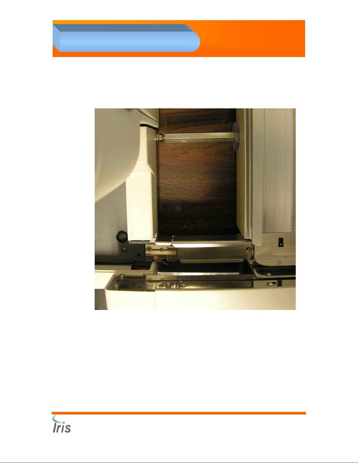
Installing the Lamina Container
• Install the Lamina cap with
filter on a fresh Lamina
container.
• Connect one end of the
Lamina tubing to the top
fitting on the right side of
the analyzer. Connect the
other end to the fitting of
the Lamina cap.
Connecting the Drain Tubing
• Connect the drain tubing to the bottom fitting on the right side of
the analyzer.
• The Drain Tubing can be directed to the designated waste area
according to local regulations.
• If direct drainage is not an option, slide the Drain Tubing inside a
waste container (approximately 2 in. (5cm)) Make sure the waste
container is lower than the microscopy module.
Iris Diagnostics, a Division of Iris International, Inc.
®
iQ
200 Sprint™ (2G) Automated Urine Microscopy Analyzer Service Manual 300-4949 Rev A 01/2005 2-7
Page 24

2. Installation Procedures
Computer Connections
1. Connect the video monitor cable to the video monitor and the video port.
2. Connect the keyboard cable to the keyboard port.
3. Connect the mouse cable to the mouse port.
4. Connect the power cord into the power inlet, and then plug into an
electrical outlet.
5. Connect the printer cable to the printer and the printer port.
6. Connect the 100-pin camera data cable to the frame grabber port.
7. Connect one end of the RS232 cable to the serial port on the
computer; connect the other end to the serial port 1 (top port) on the
®
back of the
iQ
200.
Iris Diagnostics, a Division of Iris International, Inc.
®
iQ
200 Sprint™ (2G) Automated Urine Microscopy Analyzer Service Manual 300-4949 Rev A 01/2005 2-8
Page 25

2. Installation Procedures
iQ200 Rear Panel SIC Connection Configurations
WARNING: Before making any connections to Load or Unload ports on
the Rear Panel SIC of the iQ200, ensure the jumpers are in the correct
configuration depending on the system options.
AX-4280 Connection to the iQ200
The second port labeled
“Load” should have all
three jumpers removed
from the port. CAUTION! If
the jumpers are not
removed, a fuse will blow
on the backplane of the
card cage (F10) inside the
Microscopy Module.
Load Station Connection to the
iQ200
The second port labeled
“Load” should have all
three jumpers installed in
the port. CAUTION! If the
jumpers are not in place,
the connection will not
work and no power will be
supplied to the Load
Station.
Unload Station Connection to
the iQ200
The third port labeled
“Unload” should have all
three jumpers installed in
the port. CAUTION! If the
jumpers are not in place,
the connection will not
work and no power will be
supplied to the unload
Station. Currently, the only
configuration for this port is
all three jumpers in place.
Iris Diagnostics, a Division of Iris International, Inc.
®
iQ
200 Sprint™ (2G) Automated Urine Microscopy Analyzer Service Manual 300-4949 Rev A 01/2005 2-9
Page 26

2. Installation Procedures
iQ200 / AX-4280 Bridge Installation Instructions
“iQ200-AX4280 Sample bridge kit” PN 800-3501.
1. Remove left side cover from the AX-4280
sampler.
2. Unplug connector # S1-10 (white label) from
the circuit board and replace with connector#
S1-10 (Side Sampler) stored in bottom of
sampler.
3. At the bottom of the sampler, remove the
screw (as indicated on the picture on the right)
securing carry arm stop post. Remove the
post from the sampler.
4. Extend the lever from the sampler. Attach the
rack push arm to the lever with two (2, M3x5)
flat head and one (1, M3x6 pan head) screws.
5. Break the tab on the side cover to allow the
rack to transfer from the Load Station to the
sampler.
6. Replace left side cover.
7. Back out the screw located inside the right
frame of the test strip disposal compartment to
hold the spring loaded return plate.
8. Install the new waste box provided with the
connection kit.
9. Install an alignment bracket under each
analyzer aligning the pins with the two holes
located under the front of each instrument.
Align the brackets and join with the connection
bracket. Secure with four (4, M3x10 pan head)
screws.
Iris Diagnostics, a Division of Iris International, Inc.
®
iQ
200 Sprint™ (2G) Automated Urine Microscopy Analyzer Service Manual 300-4949 Rev A 01/2005 2-10
Page 27

2. Installation Procedures
10. Install the bridge faceplate between the two
samplers. Center and secure with the
thumbscrews located underneath the
faceplate.
11. Secure the bridge between the two samplers
with two (2, M3x6 flat head) screws. Make
sure the guide spring points to the left. Check
for proper alignment and adjust the analyzer
level and/or position to provide a smooth
transition.
12. Make the cable connections between the
analyzers, and the computer according to the layout diagram.
NOTE: Do not use the grey cable provided with the Arkray kit, the pin out
for this cable will not work due to incorrect pin positioning.
Iris Diagnostics, a Division of Iris International, Inc.
®
iQ
200 Sprint™ (2G) Automated Urine Microscopy Analyzer Service Manual 300-4949 Rev A 01/2005 2-11
Page 28

REMOVE jumpers on
COM2 “Load” port
before connecting
directly to AX-4280
2. Installation Procedures
Iris Diagnostics, a Division of Iris International, Inc.
®
iQ
200 Sprint™ (2G) Automated Urine Microscopy Analyzer Service Manual 300-4949 Rev A 01/2005 2-12
Page 29

2. Installation Procedures
13. Power up the AX-4280 while holding the STOP button to access the
Service mode.
a. Press -4280-.
b. Press 1: “User set up” then press 2: “User detail”.
c. Press ENTER until “Sampler” is displayed.
d. Press the “-” button until [LOWER] is displayed and then press
ENTER.
e. Save these settings when prompted.
f. Press ESC until the first menu is displayed.
g. Press 2: “Adjust”. Press 2: “Pulse & LED”. Press 1: “Pulse
adjust”.
h. Press the “-“ button until [RACK] is displayed, then press ENTER.
i. Press the “-“ button until [Carry send] is displayed. Place a rack
on the left side of the AX-4280 sampler in the area where the rack
can be transferred to the iQ200 from the AX-4280 and press
ENTER. Verify that the carry arm moves the rack to the iQ
sampler and is positioned on the iQ 200 sampler fully.
j. If the distance needs to be adjusted, change the pulse number on
the AX-4280 to the proper position. A larger number carries the
rack further. Use the keypad to change the value.
Press 7 to increase the pulse number by 1
Press 4 to decrease the pulse number by 1
Press 9 to increase the pulse number by 10
Press 6 to decrease the pulse number by 10
k. Press MENU until the third menu is displayed.
l. Press 2: System Option. Press 1: Edit rack ID.
m. Enter the following rack ID information-
Rack numbers 1-11 Standard ID
Rack number 12 Start
Rack numbers 13-24 Standard ID
Rack numbers 25-27 Standard ID
Rack number 28 STAT/CTRL
Rack numbers 29-30 PASS
Rack number 31 NONE
14. Save these settings when prompted.
15. Return to Standby mode.
Iris Diagnostics, a Division of Iris International, Inc.
®
iQ
200 Sprint™ (2G) Automated Urine Microscopy Analyzer Service Manual 300-4949 Rev A 01/2005 2-13
Page 30

2. Installation Procedures
16. Load the AX Connectivity CD PN 700-3106 on the Analysis
Processor.
17. From the Main Menu screen of the iQ, click on the Settings button.
18. Click on Interfaces.
19. Verify that the “Enable direct connection” checkbox with the AX-
4280 is selected.
Iris Diagnostics, a Division of Iris International, Inc.
®
iQ
200 Sprint™ (2G) Automated Urine Microscopy Analyzer Service Manual 300-4949 Rev A 01/2005 2-14
Page 31

2. Installation Procedures
20. Run a patient barcoded sample tube with diluent on the AX-4280 and
verify the rack transfers to the iQ 200 without error and the chemistry
results attach to the microscopy results.
21. If the chemistry results do not cross over to the worklist, check the LIS
output on the AX-4280 for correct setup:
i. Enter “-4280-“
ii. Enter “1” for user setup
iii. Press “MENU”
iv. Press “2” for Online
v. Press “ENTER” until “RS232C Normal” is displayed
vi. Change “RS232C Normal” to ”ON” by pressing “-“, then press
ENTER
vii. Change “RS232C STAT” to “ON” by pressing “-“, then press ENTER
viii. Change “RS232C Ctrl” to “ON” by pressing “-“, then press ENTER
ix. SAVE? Yes (1) No (0) Press “1” to save
x. Press “ESC”, then press “STOP”, AX-4280 will initialize
22. If the chemistry cross over but do not attach to the microscopy, make
sure the barcode reader is setup correctly and reads the label the
same on both units. The label ID’s should match in order to attach the
chemistry and microscopy results together.
Iris Diagnostics, a Division of Iris International, Inc.
®
iQ
200 Sprint™ (2G) Automated Urine Microscopy Analyzer Service Manual 300-4949 Rev A 01/2005 2-15
Page 32

2. Installation Procedures
Optional Load/Unload Station Installation
Load Station - iQ200 Connection
NOTE: The Load Station may be connected to either the AX-4280 or the
iQ200.
1. Remove the right side cover from the iQ200 sampler.
2. Break the tab on the side cover to allow the rack to transfer from the
Load Station to the Sampler.
3. Reinstall the right side cover. DO NOT install the bottom screw
located on the backside of the sampler cover.
4. Assemble the bridge (see picture below)
Note
position of
guide plate
Securing
Brace
Load station bridge assembly
Iris Diagnostics, a Division of Iris International, Inc.
®
iQ
200 Sprint™ (2G) Automated Urine Microscopy Analyzer Service Manual 300-4949 Rev A 01/2005 2-16
Page 33
2. Installation Procedures
5. Connect the assembled bridge between the iQ200 sampler and the
load station. (see picture below)
6. Attach the load station cable to port 2 labeled “Load” on the Rear
Panel SIC (jumpers in.)
Iris Diagnostics, a Division of Iris International, Inc.
®
iQ
200 Sprint™ (2G) Automated Urine Microscopy Analyzer Service Manual 300-4949 Rev A 01/2005 2-17
Page 34

2. Installation Procedures
7. Adjust the leveling feet under the Load Station to assure a smooth
transfer of racks.
8. Attach the securing brace to the bottom screw port on the backside of
the iQ200 sampler side cover. The brace mount is attached to the
Load Station with an adhesive strip. Secure the brace to the brace
mount using the setscrew. (see picture below.)
Brace
Mount
Securing
Brace
Set Screw
Iris Diagnostics, a Division of Iris International, Inc.
®
iQ
200 Sprint™ (2G) Automated Urine Microscopy Analyzer Service Manual 300-4949 Rev A 01/2005 2-18
Page 35

2. Installation Procedures
NOTE: Smooth rack transfer between stations and samplers is critical for
proper operation.
9. Turn “ON” the power switch located on the back of the Load Station.
Iris Diagnostics, a Division of Iris International, Inc.
®
iQ
200 Sprint™ (2G) Automated Urine Microscopy Analyzer Service Manual 300-4949 Rev A 01/2005 2-19
Page 36

2. Installation Procedures
Load Station - AX-4280 Connection
1. Remove the right side cover from the AX-4280 sampler.
2. Break the tab on the side cover to allow the rack to transfer from the
Load Station to the Sampler.
3. Disconnect and remove the optical sensor from the right side of the
sampler.
4. Unplug connector # S2-22 (white label) from the circuit board and
replace with connector# S2-22 (side sampler) stored in the bottom of
the sampler. Push the sensor cable inside the sampler cover.
5. Remove the metal base plate from the STAT station.
6. Extract the sensor cable located on the right side of the STAT holder.
7. Install the new metal base plate, (included in with the load station) in
the STAT station, passing the sensor cable through the hole on the
right of the plate.
8. Attach the new metal base plate using the screws from the original
plate.
9. Remove the black optical sensor from the mounting bracket, and
connect it to the sensor cable at the STAT station.
10. Secure the black optical sensor to the side of the base plate touching
the front of the sampler, using the hardware included in the bridge
connection kit. (see picture below)
Iris Diagnostics, a Division of Iris International, Inc.
®
iQ
200 Sprint™ (2G) Automated Urine Microscopy Analyzer Service Manual 300-4949 Rev A 01/2005 2-20
Page 37

2. Installation Procedures
11. Install and secure the sensor cover to the base plate. (see picture
below)
Note
position of
guide plate
12. Reinstall the right side cover. DO NOT install the bottom screw
located on the backside of the sampler cover.
13. Assemble the bridge (see picture below)
Load station bridge assembly
Iris Diagnostics, a Division of Iris International, Inc.
®
iQ
200 Sprint™ (2G) Automated Urine Microscopy Analyzer Service Manual 300-4949 Rev A 01/2005 2-21
Page 38

2. Installation Procedures
14. Connect the assembled bridge between the AX-4280 sampler and
the load station. (see picture below)
15. Adjust the leveling feet under the Load Station to assure a smooth
transfer of racks.
Iris Diagnostics, a Division of Iris International, Inc.
®
iQ
200 Sprint™ (2G) Automated Urine Microscopy Analyzer Service Manual 300-4949 Rev A 01/2005 2-22
Page 39

2. Installation Procedures
16. Attach the securing brace to the bottom screw port on the backside of
the AX-4280 sampler cover (see picture below.)
Brace
Mount
Securing
Brace
Set Screw
NOTE: Smooth rack transfer between stations and samplers is critical for
proper operation.
17. Attach the load station cable to port labeled “Start” on the Rear Panel
of the AX-4280.
18. Power up the AX-4280 while holding the STOP button to access the
Service mode.
a. Press -4280-.
b. Press 1: “User set up” then press 2: “User detail”.
c. Press ENTER until “Sampler” is displayed.
d. Press the “-” button until [UP & LOW] is displayed and then press
ENTER.
19. Save these settings when prompted.
20. Turn “ON” the power switch located on the back of the Load Station.
Iris Diagnostics, a Division of Iris International, Inc.
®
iQ
200 Sprint™ (2G) Automated Urine Microscopy Analyzer Service Manual 300-4949 Rev A 01/2005 2-23
Page 40

2. Installation Procedures
Unload Station
1. Remove left side cover from the iQ200
sampler.
2. Unplug connector # S1-10 (white label) from
the circuit board and replace with connector#
S1-10 (side sampler) stored in the bottom of
the sampler.
3. On the bottom side of the sampler, remove
the screw (as indicated on the picture on the
right) securing the carry arm stop post.
Remove the post from the inside of the
sampler.
4. Extend the lever from the sampler. Attach the
rack push arm to the lever with two (2, M3x5)
flat head and one (1, M3x6 pan head) screws.
5. Break the tab on the side cover to allow the
leaver to extend when the cover is in place.
6. Reinstall the left side sampler cover. DO NOT install the bottom
screw located on the backside of the sampler cover.
7. Assemble the bridge (see picture below)
Note
position of
guide plate
®
iQ
200 Sprint™ (2G) Automated Urine Microscopy Analyzer Service Manual 300-4949 Rev A 01/2005 2-24
Unload station bridge assembly
Iris Diagnostics, a Division of Iris International, Inc.
Page 41

2. Installation Procedures
8. Connect the assembled bridge between the iQ200 sampler and the
Unload station. (see picture below)
9. Adjust the leveling feet under the Unload Station to assure a smooth
transfer of racks.
Iris Diagnostics, a Division of Iris International, Inc.
®
iQ
200 Sprint™ (2G) Automated Urine Microscopy Analyzer Service Manual 300-4949 Rev A 01/2005 2-25
Page 42

2. Installation Procedures
10. Attach the securing brace to the bottom screw port on the backside of
the iQ200 sampler cover. (see picture on the right)
NOTE: Smooth rack transfer between stations and samplers is critical for
proper operation.
11. Attach the unload station cable to port 3
labeled “Unload” on the Rear Panel SIC
(jumpers in.)
12. Turn “ON” the power switch located on the
back of the Unload Station.
13. Enter the Service Application and calibrate
the STM Unload station cal value cal[3]
“Distance to eject to stock yard” so the
rack transfers the correct distances onto
the unload station. The rack should
transfer smoothly and end up 3mm from
the left side of the unload station.(See
Sampler Calibration Chapter 4)
Iris Diagnostics, a Division of Iris International, Inc.
®
iQ
200 Sprint™ (2G) Automated Urine Microscopy Analyzer Service Manual 300-4949 Rev A 01/2005 2-26
Page 43

2. Installation Procedures
Startup
Note: Before power up, check inside the instrument and ensure the
cables and tubing are secured and remove any packaging material.
Turn on power in the following order:
1. Computer
2. Video monitor
3. Main power switch on the back of the
Microscopy Module
Note: Wait until the Instrument screen is
displayed. Check the status on the top left
corner of the screen is “OFF”.
4. Press the green ON/OFF button on the
front of the Microscopy Module
5. Press the ON/OFF button on the back
of the Loading/Unloading stations.
6. Remove the panel and the EMI shielding from the left side of the
Microscopy Module to access the card cage.
Note: Verify NO red LEDs are present on the circuit boards inside the
cardcage. If red LEDs are observed, clear the fault before continuing the
installation.
7. Logon to the workstation. Identifier [IRIS] password iris2k1
(lowercases).
Note: Verify the Microscopy Module is in Standby mode as indicated by a
status light (green) on the instrument and displayed on the top left side of
the screen.
8. After startup, the Lamina tank located inside the Microscopy Module
will fill automatically.
9. Place three tubes in the first three positions of the Control rack. Fill
each tube with Iris Diluent.
10. Run the Control rack twice to prime the lines located after the Lamina
tank.
Iris Diagnostics, a Division of Iris International, Inc.
®
iQ
200 Sprint™ (2G) Automated Urine Microscopy Analyzer Service Manual 300-4949 Rev A 01/2005 2-27
Page 44

2. Installation Procedures
Run Focus
1. Place provided Focus barcode label onto a glass sample tube.
2. Place a sample tube with 6 mL of iQ Focus material (REF 475-0060)
in position 5 of the Control rack.
3. Load the Control rack onto right side of the
4. Press the Start on the top left side of the Microscopy Module.
Run Calibration Rack
1. Transfer 3 mL of iQ Calibrator into 10 round-bottom 16 x 100 mm
glass test tubes.
NOTE: Do not use plastic tubes or pipetting devices.
2. Place provided barcodes on each test tube and place the test tubes
into the Calibration rack (gray inserts).
3. Load the Calibration rack onto right side of the
4. Press the Start on the top left side of the Microscopy Module.
5. Verify the Run Equivalency Factor (REF) is between 1.4 and 2.7.
iQ
200 sampler.
iQ
200 sampler.
Run Control Rack
1. Place provided Positive and Negative barcode labels onto glass
samples tubes (one each).
2. Load the tubes into a control rack, positions 6 and 7.
3. Fill the tubes with 3 mL of control.
5. Load the Control rack onto right side of the
6. Press the Start on the top left side of the Microscopy Module.
7. Verify the QC values are within the specifications.
8. Repeat Control rack 10 times and verify CV’s of < 5% for the positive
control runs.
Verify Load/Unload and Bridge Connections
1. Transfer 6 mL of Iris Diluent into five sample tubes.
2. Place one sample tube per rack at positions 1 or 10.
3. Place the five racks into the Load Station.
4. Verify that the transfer between each station and samplers are
smooth and level, and that racks travel throughout the system without
jam or error.
iQ
200 sampler.
Iris Diagnostics, a Division of Iris International, Inc.
®
iQ
200 Sprint™ (2G) Automated Urine Microscopy Analyzer Service Manual 300-4949 Rev A 01/2005 2-28
Page 45

2. Installation Procedures
Preparation for Starting Operation
Perform Setup
See Operator’s Manual - Setup.
Iris Diagnostics, a Division of Iris International, Inc.
®
iQ
200 Sprint™ (2G) Automated Urine Microscopy Analyzer Service Manual 300-4949 Rev A 01/2005 2-29
Page 46

3. Components
3
Components
Sample Transport Mechanism .......................................................................................3-3
Sampler # 700-3006 ................................................................................................... 3-3
Specimen Tube Detector # 700-3725.........................................................................3-4
Barcode Reader # 700-3315.......................................................................................... 3-5
Specimen Presentation Assembly # 700-3700 .............................................................. 3-6
Crash Detect Function................................................................................................ 3-6
Waste/Rinse Well # 700-3830 .......................................................................................3-7
Diaphragm Pumps .........................................................................................................3-8
Air Pump # 700-3877..................................................................................................3-8
Waste Pump # 700-3809............................................................................................3-8
Rinse Pump # 700-3874.............................................................................................3-8
Fill Pump # 700-3874 .................................................................................................3-8
Peristaltic Pumps # 700-3820 ......................................................................................3-10
Cannula Pump..........................................................................................................3-10
Lamina Pump ...........................................................................................................3-10
Evacuation Pump .....................................................................................................3-10
Pump Cover Closed and Cassette-In-Place Detection .........................................3-10
Lamina Tank # 700-3784 .............................................................................................3-12
Air Tank # 700-3802 ....................................................................................................3-13
Valves ..........................................................................................................................3-14
Solenoid Valves........................................................................................................3-14
Drain Valve # 700-3844 ........................................................................................3-14
Evacuation Bypass Valve # 700-3843 ..................................................................3-14
Lamina Bypass Valve # 700-3842 ........................................................................ 3-14
Cannula Bypass Valve # 700-3881.......................................................................3-14
Pipettor Bypass Valve # 700-3880........................................................................3-14
Air Valves .................................................................................................................3-15
Air Mix Valve # 700-3887......................................................................................3-15
Air Charge Valve # 700-3888................................................................................3-15
Optical Bench Assembly #700-3500............................................................................ 3-16
Flow Cell # 525-3077............................................................................................3-17
Strobe Light # 065-0059 .......................................................................................3-17
CCD Camera # 700-3565 ..................................................................................... 3-17
20 x Objective # 220-3009 .................................................................................... 3-17
Iris Diagnostics, a Division of Iris International, Inc.
®
iQ
200 Sprint™ Automated Urine Microscopy Analyzer Service Manual 300-4949 Rev A 01/2005 3-1
Page 47

3. Components
Auto Focus System # 700-3505............................................................................3-17
Power System Assembly # 230-3000 .......................................................................... 3-18
Cooling Fans # 700-3892 & 700-3412 .........................................................................3-18
Fuses and Visible LEDs...............................................................................................3-18
Backplane Fuses and LEDs .....................................................................................3-19
PCBA Summary........................................................................................................... 3-21
Cardcage .....................................................................................................................3-22
High Level Control Board (HLCB), # 101-5057 ........................................................3-22
Motor/Scanner Control Board (MSCB), # 101-5001.................................................3-22
DC Valve Board (DCVB), # 101-5043 ...................................................................... 3-22
Stepper/Scanner/Motor Board (SSMB), # 101-5059 ................................................3-23
Backplane # 101-5003..............................................................................................3-23
Signal Interface Concentrators (SICs) ......................................................................... 3-24
Power SIC # 101-5020 ............................................................................................. 3-24
Pump SIC #101-5020 ...............................................................................................3-25
FSV SIC # 101-5045 ................................................................................................3-25
SPA SIC # 101-5004.................................................................................................... 3-27
SPA SIC Visible LEDs ..........................................................................................3-27
SPA SIC Push-Button Switches............................................................................3-28
OBA SIC #101-5053.................................................................................................3-29
Do-All SIC # 101-5046..............................................................................................3-30
Rear Panel SIC # 101-5058 .....................................................................................3-31
STM SIC # 101-5014................................................................................................3-31
Other PCBAs ...............................................................................................................3-31
Lamina ESN # 101-5048 ..........................................................................................3-31
FITD PCBA # 101-5041............................................................................................3-31
SM Status Board PCBA # 101-5032 ........................................................................3-31
STD PCBA # 101-5034 ............................................................................................3-31
Pressure Transducer Board #101-5016 ...................................................................3-32
SPA Optical Board # 101-5052 ................................................................................3-32
LED Visual Indicators................................................................................................... 3-32
Iris Diagnostics, a Division of Iris International, Inc.
®
iQ
200 Sprint™ Automated Urine Microscopy Analyzer Service Manual 300-4949 Rev A 01/2005 3-2
Page 48

3. Components
Sample Transport Mechanism
The Sample Transport Mechanism refers to the mechanisms associated
with delivering test tubes of specimen to the Specimen Presentation
Assembly. The STM is composed of the Sampler and the Specimen
Tube Detector.
Specimen Tube Detector
Sampler # 700-3006
The Sampler is located on the front of the
sampler used on the AX-4280. A bridge connection can be installed
between the two systems allowing automatic transfer of sample racks
after they have been processed on the AX-4280.
Sample racks, each capable of holding 10 tubes, are loaded on the right
side of the sampler. To start the transport of the racks to the pipetting
station, the operator presses the “Start” button. The Sampler presents
sample tubes loaded onto racks at the pipetting station. The Sampler
also has electro-optical sensing of various internal (relating to motor and
actuator positions) and external (relating to rack position) status. The SM
was specifically designed to use the Arkray Sampler.
®
iQ
200 and is similar to the
Iris Diagnostics, a Division of Iris International, Inc.
®
iQ
200 Sprint™ (2G) Automated Urine Microscopy Analyzer Service Manual 300-4949 Rev A 01/2005 3-3
Page 49

3. Components
Specimen Tube Detector # 700-3725
This small assembly uses specially focused visible light to determine if a
sample tube is present at the position where the pipette can extract
specimen. Because racks are not necessarily filled with samples tubes,
the specimen tube detector allows the Microscopy Module to skip
positions where there is no sample tube, avoiding using consumables for
non-existent specimens, and achieving higher specimen throughput.
Component drawings may change without notice. Please contact IRIS
Diagnostics to determine the current revision level.
IRIS Diagnostics
9172 Eton Ave
Chatsworth, Ca 91311
Ph# 818-709-1244
Iris Diagnostics, a Division of Iris International, Inc.
®
iQ
200 Sprint™ (2G) Automated Urine Microscopy Analyzer Service Manual 300-4949 Rev A 01/2005 3-4
Page 50

3. Components
Barcode Reader # 700-3315
The Barcode Reader uses CCD Array
optical scanning process to read
barcodes.
Component drawings may change without notice. Please contact IRIS
Diagnostics to determine the current revision level.
IRIS Diagnostics
9172 Eton Ave
Chatsworth, Ca 91311
Ph# 818-709-1244
Iris Diagnostics, a Division of Iris International, Inc.
®
iQ
200 Sprint™ (2G) Automated Urine Microscopy Analyzer Service Manual 300-4949 Rev A 01/2005 3-5
Page 51

3. Components
Specimen Presentation Assembly # 700-3700
The SPA or “Specimen Presentation Assembly,” is associated with the
“front end” handling of the urine. Mechanically, the SPA mixes the
specimen within the sample tube for uniform particle distribution,
aspirates sample from the test tube, and delivers it to the next process in
the Microscopy Module. The pipette (a vertical two-lumen tube) is
mounted onto a two-axis arm, and provides the means for positioning the
pipette down into the sample tube. The SPA includes two DC motors with
integral encoders—one for vertical translation of the pipette arm, and one
for rotation of the pipette arm.
Top board
Crash Detect Function
The Crash Detect function senses one switch (of a pair of snap-action
switches mounted on the SPA arm itself). A latched relay on the SPA
SIC is held pulled-in until the Hard Crash switch on the SPA arm opens
(due to a crash), the relay drops out, and drive to the vertical motor is
interrupted. When the relay is pulled in, the green “Vert OK” LED is on.
When the relay is dropped out, the red “Vert Crash” LED is on. At
Microscopy Module power-up, the Hard Crash condition is automatically
reset by an alternate signal on the SPA SIC. There is a push-button
switch on the SPA SIC to manually reset the Hard Crash condition if the
incoming Hard Crash signal (from the Hard Crash switch on the SPA arm)
is no longer asserted. Under normal conditions, the manual switch is not
used. Even when the vertical motor is disabled by the crash relay
dropping out, the SPA SIC will still allow upward vertical motion of the
SPA arm, but not downward motion.
Pipette
Belt
Rotation motor
Vertical motor
Iris Diagnostics, a Division of Iris International, Inc.
®
iQ
200 Sprint™ (2G) Automated Urine Microscopy Analyzer Service Manual 300-4949 Rev A 01/2005 3-6
Page 52

3. Components
Waste/Rinse Well # 700-3830
The Rinse function is used to fill the well
with Lamina in order to clean the pipette
between sampling.
The Waste function collects all waste
liquids (samples and Lamina) used during
sample processing, then drains the fluids
through the Waste Pump into the waste
tubing.
Component drawings may change without notice. Please contact IRIS
Diagnostics to determine the current revision level.
IRIS Diagnostics
9172 Eton Ave
Chatsworth, Ca 91311
Ph# 818-709-1244
Iris Diagnostics, a Division of Iris International, Inc.
®
iQ
200 Sprint™ (2G) Automated Urine Microscopy Analyzer Service Manual 300-4949 Rev A 01/2005 3-7
Page 53

3. Components
Diaphragm Pumps
The diaphragm pumps are DC motor driven pumps located on the left
side of the instrument next to the sampler. They are from left to right:
1. Air Pump
2. Waste Pump
3. Rinse Pump
4. Fill Pump
Air Pump # 700-3877
This pump fills the air tank and is used for mixing the specimen through
the charge and air mix valves.
Waste Pump # 700-3809
This pump drains the waste well.
Rinse Pump # 700-3874
This pump fills the rinse well for cleaning the pipette.
Fill Pump # 700-3874
This pump maintains the level inside the Lamina tank.
Iris Diagnostics, a Division of Iris International, Inc.
®
iQ
200 Sprint™ (2G) Automated Urine Microscopy Analyzer Service Manual 300-4949 Rev A 01/2005 3-8
Page 54

3. Components
Component drawings may change without notice. Please contact IRIS
Diagnostics to determine the current revision level.
IRIS Diagnostics
9172 Eton Ave
Chatsworth, Ca 91311
Ph# 818-709-1244
Iris Diagnostics, a Division of Iris International, Inc.
®
iQ
200 Sprint™ (2G) Automated Urine Microscopy Analyzer Service Manual 300-4949 Rev A 01/2005 3-9
Page 55

3. Components
Peristaltic Pumps
Cannula Pump # 700-3820
This pump is used to push the sample into the Flow Cell.
Lamina Pump # 700-3804
This pump is used to backwash the fluidic system. During sample
processing, the pump is in Home position allowing Lamina to be directed
into the Flow Cell.
Evacuation Pump # 700-3820
This pump is used to:
• aspirate the sample into the pipette
• evacuate liquids from the Flow Cell to the Waste Well
• draw Lamina into the Flow Cell when the Lamina Pump is in
Home position.
Pump Cover Closed and Cassette-In-Place Detection
Three switches are located on the Pump SIC for cover-closed detection,
and for cassette-in-place detection.
The cover-closed detection senses the end of the shaft of the threaded
knob that closes the pump cover. If the knob is not fully screwed, the
pump will not run.
The Cassette-In-Place detection senses the presence of a small tab on
the cassette indicating that the cassette has been inserted into the pump.
If the tab is not detected, the pump will not run.
Iris Diagnostics, a Division of Iris International, Inc.
®
iQ
200 Sprint™ (2G) Automated Urine Microscopy Analyzer Service Manual 300-4949 Rev A 01/2005 3-10
Page 56

3. Components
Component drawings may change without notice. Please contact IRIS
Diagnostics to determine the current revision level.
IRIS Diagnostics
9172 Eton Ave
Chatsworth, Ca 91311
Ph# 818-709-1244
Iris Diagnostics, a Division of Iris International, Inc.
®
iQ
200 Sprint™ (2G) Automated Urine Microscopy Analyzer Service Manual 300-4949 Rev A 01/2005 3-11
Page 57

3. Components
Lamina Tank # 700-3784
The Lamina Tank, located on a bracket
above the air tank, is used as a reserve
to avoid running out of Lamina. The Fill
pump fills the Lamina Tank directly from
the external Lamina container.
Four liquid level sensors are inside the
Lamina tank. From top to bottom:
1. Overflow detector – when this level is reached, the Fill
Pump stops filling the tank.
2. Refill detector – when this level is reached, the Fill
Pump is activated to refill the tank.
3. Low-level detector – the external Lamina container is
empty. An error message with medium priority is
generated, sample processing continues.
4. Empty level detector – the external Lamina container
is empty. An error message with high priority is
generated; sample processing is stopped until a new
container is installed.
4
2
1
3
Iris Diagnostics, a Division of Iris International, Inc.
®
iQ
200 Sprint™ (2G) Automated Urine Microscopy Analyzer Service Manual 300-4949 Rev A 01/2005 3-12
Page 58

3. Components
Air Tank # 700-3802
The Air Tank maintains air pressure used for the air mixing of the
specimen inside the sample tube before pipetting.
Component drawings may change without notice. Please contact IRIS
Diagnostics to determine the current revision level.
IRIS Diagnostics
9172 Eton Ave
Chatsworth, Ca 91311
Ph# 818-709-1244
Iris Diagnostics, a Division of Iris International, Inc.
®
iQ
200 Sprint™ (2G) Automated Urine Microscopy Analyzer Service Manual 300-4949 Rev A 01/2005 3-13
Page 59

3. Components
Valves
Solenoid Valves
Located inside the microscopy
module, on the right of the Lamina
Tank, from top to bottom:
Drain Valve # 700-3844
The Drain Valve is used to remove
any air bubble present inside the
Flow Cell.
Evacuation Bypass Valve # 700-3843
When this valve is opened, the Evacuation Peristaltic pump aspirates
fluids from the drain outlet of the Flow Cell into the Waste Well.
When closed, the valve diverts the flow from the Evacuation Pump to the
Waste Well.
Lamina Bypass Valve # 700-3842
When this valve is opened, Lamina goes to the Waste Well.
When closed, Lamina goes to the Flow Cell.
Cannula Bypass Valve # 700-3881
When this valve is opened, Lamina goes to the Flow Cell via the Pipettor
Bypass Valve.
When closed, Lamina goes to the Waste Well.
Pipettor Bypass Valve # 700-3880
Located on the Specimen Presentation Assembly. When this valve is
opened, sample and/or Lamina go to the Flow Cell.
When closed, sample is aspirated in the flow line.
Iris Diagnostics, a Division of Iris International, Inc.
®
iQ
200 Sprint™ (2G) Automated Urine Microscopy Analyzer Service Manual 300-4949 Rev A 01/2005 3-14
Page 60

3. Components
Air Valves
The Air Valves are located on the right front side of the instrument,
underneath the Optical Bench Assembly.
Air Mix Valve # 700-3887
The Air Mix Valve is used to mix the specimen
inside the sample tube.
Air Charge Valve # 700-3888
The Air Charge Valve is used to refill the
pressure in the Air Line for the mixing circuit.
Iris Diagnostics, a Division of Iris International, Inc.
®
iQ
200 Sprint™ (2G) Automated Urine Microscopy Analyzer Service Manual 300-4949 Rev A 01/2005 3-15
Page 61
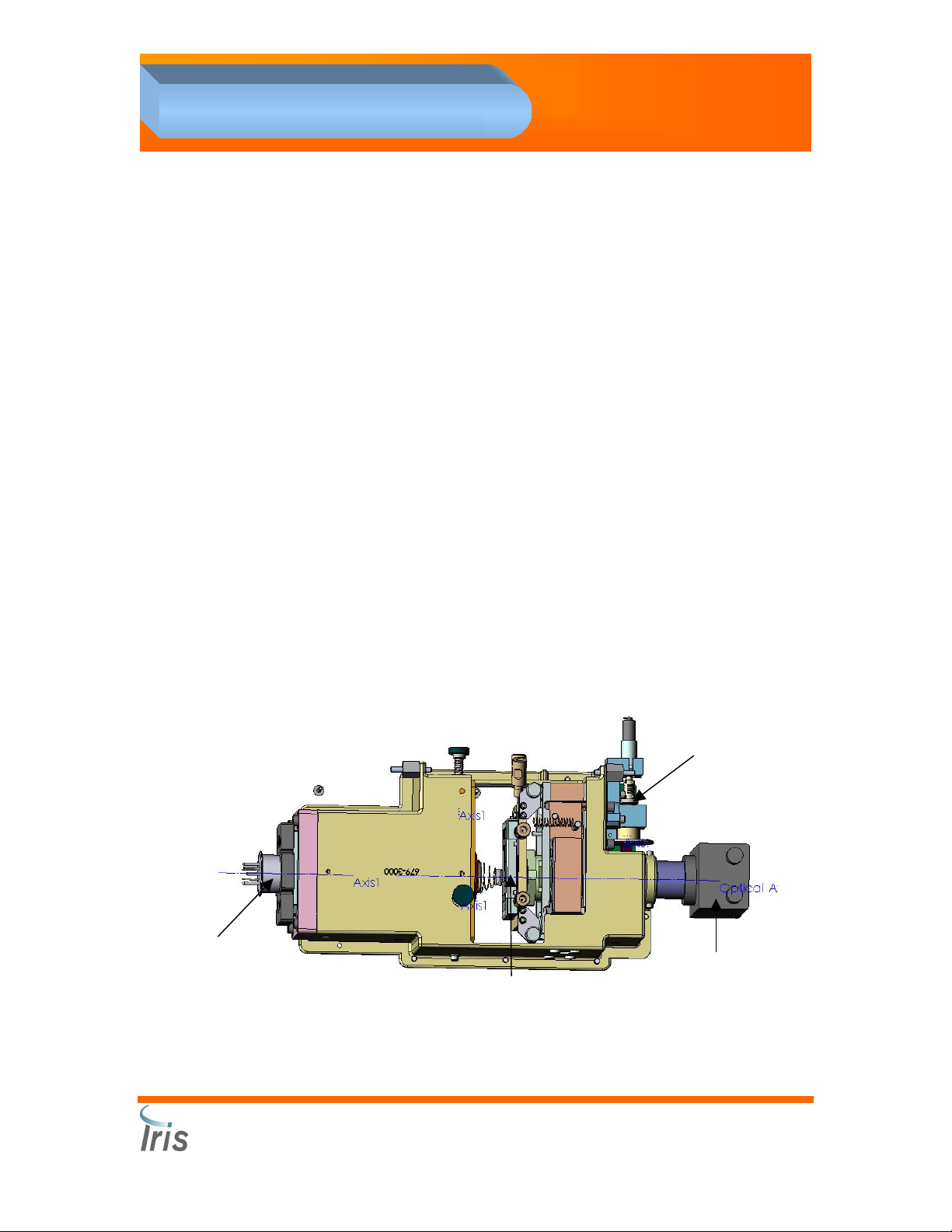
3. Components
Optical Bench Assembly #700-3500
Sample is presented as a lamina sandwiched between enveloping layers
of suspending fluid. The fluids pass into the Flow Cell in front of a
microscope. The lamination positions the specimen exactly within the
depth of focus and field of view of the objective lens of the microscope. A
CCD (charge coupling device) video camera, connected to the
microscope, captures five hundred frames per sample, as each
microscopic field of view is illuminated by the flash of a strobe lamp. The
resulting pictures are digitized and delivered to the Analysis Processor
computer.
The Optical Bench Assembly (OBA) is a mechanical/electro-optical
assembly that provides for the microscopic images of a transmissivelyilluminated ultra-thin sheet of the specimen to be captured as a video
image by the CCD camera. Three thermistors are mounted on different
component parts of the OBA to check that the temperature is stable.
When temperatures are changing, because of the sub-micron accuracy
required for proper images the OBA requires re-focusing.
The mechanical part of the OBA includes:
1. Flow Cell
2. Strobe Light
3. CCD camera
4. 20 x Objective
Auto Focus Motor
Strobe Light
Flow Cell
CCD camera
5. Auto Focus Motor
Iris Diagnostics, a Division of Iris International, Inc.
®
iQ
200 Sprint™ (2G) Automated Urine Microscopy Analyzer Service Manual 300-4949 Rev A 01/2005 3-16
Page 62

3. Components
Flow Cell # 525-3077
This precision assembly is where the thin sheet of liquid specimen is
presented in a continuous flow microscope-slide manner for observation
by the image capturing system. The sample is pulled into the Flow Cell
by the Evacuation pump. Lamina encases the sample, keeping the
specimen in thin sheet, and keeps the specimen away from the Flow Cell
surfaces to minimize surface contamination.
Strobe Light # 065-0059
The strobe light provides short, high-intensity, parallel-light strobe-light
pulses on a controlled basis through the thin sheet of specimen. This
subsystem includes a 400V to 1000V strobe power supply and a high
intensity strobe flash tube.
CCD Camera # 700-3565
The CCD camera, coupled to the Microscope, takes magnified highresolution digital pictures of the sample going through the Flow Cell.
20 x Objective # 220-3009
The objective magnifies the sample going through the Flow Cell.
Autofocus Motor ” Micro-nudger” # 700-3505
This mechanism allows moving the Flow Cell into the appropriate position
where the thin specimen is focused for image capture. Focus position is
achieved with an ultra-fine-pitch stepper motor providing a movement of
about 0.2 microns per full step.
Iris Diagnostics, a Division of Iris International, Inc.
®
iQ
200 Sprint™ (2G) Automated Urine Microscopy Analyzer Service Manual 300-4949 Rev A 01/2005 3-17
Page 63

3. Components
Power Supply # 230-3000
This assembly includes the international-voltage-range AC-line-to-DC
converters to generate +24V and +5V regulated DC for the entire
Microscopy Module, and the strobe power supply. The regulated
voltages out of the Power system assembly are brought to the Power SIC
through a 10-wire cable and a locking Molex connector.
Cooling Fans # 700-3892 & 700-3412
While the Microscopy Module is designed
to operate with only natural convection, at
higher ambient temperatures, it may be
necessary to use some forced-air cooling.
Two fans are present: one in the card
cage area, and one in the main instrument
area. These fans are turned on by +24V
power switched on when the temperature
sensed by a local thermistor goes above
o
34
C ± 1oC and switched off when the
temperature goes below 29
These fans plug into individual 2-pin connectors on the Backplane.
o
C ± 1oC.
Fuses and Visible LEDs
The fuses are quick-acting, miniature and pluggable. The fuse socket is
soldered to the PCB and has a threaded plastic cap that mechanically
retains the fuse. Three different
fuse ratings are used:
• 0.50 A Iris 056-3000
• 1.0 A Iris 056-3004
• 2.5 A Iris 056-3001
The Backplane has 22 fuses and
22 visible red LEDs. Each LED is
associated with a power protection
fuse, and the LED lights only when
DC power is on (via the Power
SIC) and the fuse is blown.
Iris Diagnostics, a Division of Iris International, Inc.
®
iQ
200 Sprint™ (2G) Automated Urine Microscopy Analyzer Service Manual 300-4949 Rev A 01/2005 3-18
Page 64

3. Components
The fuses are mounted in two rows, with even number fuses on the top
and odd numbered fuses on the bottom; fuse numbers increasing from
left to right. The LEDs are mounted in a single row between the fuses,
and each vertically aligned with its associated fuse.
Assignment of these Fuses and LEDs is given in the table below where
the “Protects power through” column refers to the Backplane connector
through which the protected power leaves the Backplane PCBA.
Note that three of the fuses have their power provided through SSMB
circuits, and the LEDs will not light, even when the fuse is blown, if the
corresponding SSMB is not plugged into the Backplane.
Backplane Fuses and LEDs
Fuse &
LED
Fuse
Rating
Protects
power
through
Voltage and Function Protected
F3 D3 0.50A J19 +5V SPA SIC
F4 D4 2.5A J20
F5 D5 2.5A J20 +24V Sampler front stepper (through SSMB1)
F6 D6 0.50A J23 +5V Pump SIC: Lamina Pump, STM SIC
F7 D7 0.50A J22 +5V Pump SIC: Cannula Pump
F8 D8 0.50A J21 +5V STM Sampler
F9 D9 0.50A J14 +5V OBA power
F10 D10 1.0A J11 +24V Rear Panel SIC power
F11 D11 2.5A J18 +24V Do-All SIC power
F12 D12 0.50A J18 +5V Do-All SIC power
F13 D13 0.50A J11 +5V Rear Panel SIC power
+24V Sampler measurement stepper (through
SSMB1)
F14 D14 0.50A J21 +24V Sample Transport Module SIC power
Iris Diagnostics, a Division of Iris International, Inc.
®
iQ
200 Sprint™ (2G) Automated Urine Microscopy Analyzer Service Manual 300-4949 Rev A 01/2005 3-19
Page 65

3. Components
Fuse &
LED
F15 D15 0.50A J14
F16 D16 0.50A J10 +5V Status Board power
F17 D17 0.50A J12 +5V FSV SIC power
F18 D18 0.50A J13 +5V Barcode Reader power
F19 D19 1.0A J12 +24V FSV SIC power
F20 D20 0.50A J17 +5V Pump SIC: Evacuation Pump
F21 D21 0.50A J24, J25 +24V Fan power
F22 D22 0.50A J16 +5V Power SIC Camera Circuits power
F23 D23 2.5A J16 +24V Strobe Power Supply power
F24 D24 1.0A J16 +24V Camera 24VDC to 12VDC Inverter power
Fuse
Rating
Protects
power
through
Voltage and Function Protected
+24V OBA focus stepper power (through
SSMB2)
Iris Diagnostics, a Division of Iris International, Inc.
®
iQ
200 Sprint™ (2G) Automated Urine Microscopy Analyzer Service Manual 300-4949 Rev A 01/2005 3-20
Page 66

3. Components
PCBA Summary
Many of the boards have LEDs indicating dynamic operating status of the
board and its controlling firmware.
Item No Board name or Sub assembly Number
1 HLCB 101-5057 1 Card cage
2 MSCB 101-5001 4 Card cage
3 DCVB 101-5043 2 Card cage
4 SSMB 101-5059 2 Card cage
5 Backplane 101-5003 1 Card Cage
6 SPA SIC 101-5004 1 Behind SPA
7 Pump SIC 101-5010 3 Behind Peri-pump
8 OBA SIC 101-5053 1 Side of Optical bench
9 STM SIC 101-5014 1
10 Pressure Transducer Board 101-5016 2
11 Power SIC 101-5020 1 Above cardcage
12 Rear Panel SIC 101-5058 1 Behind backplane
13 SM Status Board 101-5032 1 Top left front panel
14 STD Board 101-5034 1 Inside tube detector
15 FITD 101-5041 4
16 FSV SIC 101-5045 1
17 Do-All SIC 101-5046 1
18 Waste Well Electrode Board 101-5047 1 Waste well
19 ESN Board 101-5049 42
20 SPA Opto Board 101-5052 1 SPA
21 Lamina ESN Bd 101-5048 1
22 Waste Well FITD 101-5054 1 Waste well
23 OBA Focus Home 101-5055 1 Above CCD camera
# in
system
Location
Above pumps left
Valves mounting next
to optical bench
Waste well –
pressure transducer
Right board behind
lamina container
Left board behind
lamina container
Inside lamina
container
panel
Iris Diagnostics, a Division of Iris International, Inc.
®
iQ
200 Sprint™ (2G) Automated Urine Microscopy Analyzer Service Manual 300-4949 Rev A 01/2005 3-21
Page 67

9
3. Components
Cardcage
The Microscopy Module control center
is the cardcage, and is composed of
the Microscopy Module backplane,
assembly number 101-5003, and nine
circuit boards (called the Cardcage
boards). The backplane has nine 120pin DIN connectors into which the
Cardcage boards plug. The color of
the card guides for each slot position
identifies the type of board required in
the slot—the color of the board’s plastic
card ejector should match the color of
the card guide. There are also 16 other
connectors on the backplane for
interface to the rest of the SMCS
system.
1
High Level Control Board (HLCB), # 101-5057
The HLCB, located in slot #1, is the highest level controlling entity in the
Microscopy Module. It includes the Master Controller, six high-level
controllers, and the FQM low-level controller that itself controls a multipoint scanner. There is one HLCB with white card ejectors.
Motor/Scanner Control Board (MSCB), # 101-5001
The MSCB provides low-level closed-loop control over two independent
DC motor/encoders and a multi-point scanner. There are four MSCB
boards with blue card ejectors. They are interchangeable.
• Slot 2 Sample Presentation Assembly
• Slot 3 Sample Presentation Assembly
• Slot 6 Fluidic block
• Slot 7 Sample Transport Module (sampler)
DC Valve Board (DCVB), # 101-5043
The DCVB provides control for solenoid-operated valves, and includes
the ability to electrically measure activation and release operation of the
valves being controlled. There are two DCVB boards with green card
ejectors. They are interchangeable.
• Slot 4 Sample Presentation Assembly
• Slot 5 Fluidic block
Iris Diagnostics, a Division of Iris International, Inc.
®
iQ
200 Sprint™ (2G) Automated Urine Microscopy Analyzer Service Manual 300-4949 Rev A 01/2005 3-22
Page 68

3. Components
Stepper/Scanner/Motor Board (SSMB), # 101-5059
The SSMB, located in slots 8 and 9, provides control for two stepper
motors, low-level closed-loop control DC for one DC motor/encoders, and
a multi-point scanner. There are two SSMB boards with yellow card
ejectors. They are interchangeable.
• Slot 8 Sample Transport Module (sampler)
• Slot 9 Optical Bench Assembly
Backplane # 101-5003
Except for power and signal distribution, analog input signal EMI filtering,
protection of power, and fuse status resistor divider networks, the
backplane has no other function. It has no active elements.
Backplane SMCS Interconnect Connectors
Connector Type Connects to Function
J10 20-pin ribbon header SM Status Board J1 SM Status Board signals
J11 26-pin ribbon header Rear Panel SIC J5 Rear Panel SIC
J12 40-pin ribbon header FSV SIC J1 FSV Valve interface
J13 10-pin ribbon header Barcode Reader Bar Code Reader
J14 20-pin ribbon header OBA SIC J1 OBA signals
J15 10-pin ribbon header Power SIC J3 Strobe PIC control
J16 14-pin Molex
receptacle.
J17 20-pin ribbon header Evacuation Pump
J18 40-pin ribbon header Do-All SIC J1 Do-All SIC signals
J19 34-pin ribbon header SPA SIC J1 SPA SIC signals
J20 16-pin ribbon header STM SIC J12 STM Motor signals, STM J02
J21 34-pin ribbon header STM SIC J11 STM Optical signals, STM
J22 20-pin ribbon header Cannula Pump SIC
J23 20-pin ribbon header Lamina Pump SIC J1 Lamina Pump
J24 2-pin receptacle. Cardcage Fan Cardcage fan
J25 2-pin receptacle. Main SM Fan Main SM fan
Power SIC J2 Power to/from Power SIC
Evacuation Pump
SIC J1
J01, STM STD, diaphragm
pumps, STM tether ESN,
Barcode reader ESN tether.
Cannula Pump
J1
Iris Diagnostics, a Division of Iris International, Inc.
®
iQ
200 Sprint™ (2G) Automated Urine Microscopy Analyzer Service Manual 300-4949 Rev A 01/2005 3-23
Page 69

3. Components
Signal Interface Concentrators (SICs)
While the SMCS card cage is the central brain of the SMCS, the control
and monitor signals of the SMCS must reach the electrical hardware that
it is measuring and controlling. To achieve this signal distribution, the
SMCS includes many “Signal Interface Concentrators’ PCBAs (SICs)
located throughout the SM.
The SICs provide a local place where the individual elements of the
particular subsystem of the SM have their electrical signals
“concentrated.” In some cases, there is ESN capability on the SICs.
Power SIC # 101-5020
The Power SIC provides a controlled interface between the DC power
supply, and the rest of the SMCS. It also provides controlled power to the
Strobe. The Power SIC is mounted atop the SMCS Cardcage, and
interfaces to backplane connector J15 through a 10-wire ribbon
connector, and to backplane connector J16, a 14-wire discrete wire
connector with large gauge wires carrying the actual power signals. The
Power SIC receives power directly from the DC Power supply via another
10-pin discrete wire connector. It also provides 12-volt regulated power
to the CCD camera. The power delivered to the Cardcage (and the rest
of the SMCS) is switched off and on by a logical signal from the SM front
panel “Standby” switch.
The Power SIC connectors are summarized in table below.
Connect. Type Connects to Function
J1
J2
J3
J4 5-pin discrete header Cable to Video Camera
J5 6-pin discrete header
J6 3-pin discrete header
J202
J203
10-pin discrete female
header Molex MiniFit Jr
12-pin discrete female
header Molex MiniFit Jr
10-pin ribbon header
w/locks
20-pin shrouded ribbon
header
10-pin shrouded ribbon
header
Power Supply DC
terminals Cable, P1
Cable to Backplane, J16
Cable to Backplane, J15 OBA SIC PIC16 control
Cable to Strobe power
supply
Cable to SM front panel
standby-switch
(test programming cable)
(test diagnostic cable)
Unswitched regulated
power from power supply
Switched/Fused power
to/from backplane
Power to camera, sync
from camera
Strobe power, strobe
trigger
SMCS power off/on logic
control, +24V to indicator
LED in switch
PIC programming during
test
Quad RS-232 driver bd
(test & diagnostics)
Iris Diagnostics, a Division of Iris International, Inc.
®
iQ
200 Sprint™ (2G) Automated Urine Microscopy Analyzer Service Manual 300-4949 Rev A 01/2005 3-24
Page 70

3. Components
Pump SIC #101-5020
The Pump SIC concentrates the signals from the elements of a peristaltic
pump assembly, including: the DC pump motor, its rotation encoder, the
home detect optical sensor, a cassette-in-place switch and a pair of
cover-closed switches. The signals from a Pump SIC connect to the
SMCS backplane through a 20-wire ribbon cable. The three Pump SICs
in the SMCS:
1. Evacuation Pump assembly, connected into backplane connector J17,
2. Cannula Pump assembly, connected into backplane connector J22,
3. Sheath Pump assembly, connected into backplane connector J23.
The Pump SIC connectors are summarized in table below.
Connect. Type Connects to Function
J1
J2
20-pin ribbon
header
12-pin female
ESN
Backplane:
J17 (Evacuation pump)
J22 (Cannula pump)
J23 (Lamina pump)
DC motor and encoder
assy, P1
Main signals to SMCS
for: Evacuation pump,
Cannula pump, or
Lamina pump
Motor and Encoder
signals
FSV SIC # 101-5045
The Fluid System Valve (FSV) SIC concentrates the leads from up to 12
solenoid valves that operate the fluid system. The signals are brought to
SMCS backplane J25 through a 40-wire ribbon cable. The FSV SIC is
mounted alongside the Do-All SIC on the Fluid System Valve Assembly.
Iris Diagnostics, a Division of Iris International, Inc.
®
iQ
200 Sprint™ (2G) Automated Urine Microscopy Analyzer Service Manual 300-4949 Rev A 01/2005 3-25
Page 71

3. Components
The FSV SIC connectors are summarized in table below.
Connect. Type Connects to Function
J1
J2 12-pin female Not used
J3 12-pin female Not used
J4 12-pin female Not used
J5 12-pin female Not used
J6 12-pin female CBV Operates CBV
J7 12-pin female ACV Operates ACV
J8 12-pin female LBV Operates LBV
J9 12-pin female DRV Operates DRV
J10 12-pin female AMV Operates AMV
J11 12-pin female PBV Operates PBV
J12 12-pin female EBV Operates EBV
J13 12-pin female Not used
J14 12-pin female Not used
J15 12-pin female Not used
J16 12-pin female Not used
40-pin ribbon
header
Backplane J12 Main signals to SMCS
Iris Diagnostics, a Division of Iris International, Inc.
®
iQ
200 Sprint™ (2G) Automated Urine Microscopy Analyzer Service Manual 300-4949 Rev A 01/2005 3-26
Page 72

3. Components
SPA SIC # 101-5004
The SPA SIC incorporates signals from the SPA. It is mounted directly to
the SPA assembly. It has two 12-pin ESN connectors for the interface to
the two DC motors/encoders (rotational and vertical) of the SPA, an ESN
connector for the bottom vertical limit sensor, a 10-pin ribbon header for
connection to the SPA Optical Board (for detection of rotational limits and
vertical top limit), an ESN connector for the crash detection assembly,
and a final ESN connector for a tethered ESN to the entire SPA
assembly. The interface from the SPA SIC to SMCS backplane J19 is
through a 34-wire ribbon cable.
SPA SIC Visible LEDs
The SPA SIC has 7 visible LEDs though which an observer can deduce
operational status of the SPA. The LEDs are identified in table below.
Item LED legends LED color # LEDs
Vertical Motor Encoder Signals Rot A, Rot B Green 2
Horizontal Motor Encoder Signals Rot A, Rot B Green 2
Crash Status Vert OK Green 1
Crash Status Vert Crash Red 1
Motors Disabled Motors Disabled Red 1
Iris Diagnostics, a Division of Iris International, Inc.
®
iQ
200 Sprint™ (2G) Automated Urine Microscopy Analyzer Service Manual 300-4949 Rev A 01/2005 3-27
Page 73

3. Components
SPA SIC Push-Button Switches
There is a single push-button on the SPA SIC that manually resets the
Hard Crash condition if the incoming Hard Crash signal (from the Hard
Crash switch on the SPA arm) is no longer asserted.
Connect. Type Connects to Function
J1 34-pin ribbon header Backplane J19 Main signals to SMCS
J2 12-pin female
J3 12-pin female ESN
J4 12 pin female ESN
J5 12-pin female
J6 12-pin female
J10 10-pin ribbon header SPA Opto Bd
SPA Assy Tether
ESN
SPA Vertical Motor
ESN
SPA Rotation
Motor
SPA Crash
Detector Switches
SPA Bottom
Sensor switch ESN
SPA Assy ESN
SPA Vertical Motor ESN, DC
motor and encoder
SPA Rotation Motor ESN, DC
motor and encoder
SPA Crash Detection
SPA Bottom Sensor ESN and
switch
SPA vertical & rotational
homes and other limit.
Iris Diagnostics, a Division of Iris International, Inc.
®
iQ
200 Sprint™ (2G) Automated Urine Microscopy Analyzer Service Manual 300-4949 Rev A 01/2005 3-28
Page 74

3. Components
OBA SIC #101-5053
The OBA (Optical Bench Assembly) SIC incorporates all of the signals
from the optical bench. The interface to SMCS backplane J14 is through
a 20-wire ribbon cable (J1). The OBA SIC translates the unipolar stepper
drive signals from the SSMB to bipolar drives suited for the micro-stepper
used in the OBA. The OBA SIC reads the sense signals from the stepper
motor assembly to limit movement in the event of reaching a motion limit
in one direction or the other. The OBA SIC is physically mounted on the
OBA.
The OBA SIC connectors are summarized in table below.
Connector Type Connects to Function
20-pin
J1
ribbon
header
Backplane J14 Main signals to SMCS
J2
J6
J7
J8
J9
J10
J11
J12
12-pin
female
ESN
12-pin
female
ESN
12-pin
female
ESN
12-pin
female
ESN
12-pin
female
ESN
12-pin
female
ESN
12-pin
female
ESN
12-pin
female
ESN
Focus Stepper
Motor P1
OBA thermistors P1 OBA ESN
Not used Camera tethered ESN
Not used
Not used Strobe Bulb tethered ESN
Not used Strobe Bulb tethered ESN
Not used Flow Cell tethered ESN
Focus Position
Optical Sensors P1
Stepper Motor Phase Coils
Strobe Trigger Unit tethered
ESN
Iris config.: Dual opto-focus
home. Newport config.:
end limits for linear actuator.
Iris Diagnostics, a Division of Iris International, Inc.
®
iQ
200 Sprint™ (2G) Automated Urine Microscopy Analyzer Service Manual 300-4949 Rev A 01/2005 3-29
Page 75

3. Components
Do-All SIC # 101-5046
The Do-All SIC is used for interfacing to SMCS backplane J18 through a
40-wire ribbon cable, and providing a concentrating place for the cables
to all of the SMCS pressure transducers, the FITDs. The Do-All SIC is
mounted alongside the FSV SIC on the Fluid System Valve Assembly.
The Do-All SIC connectors are summarized on the table below.
Connect. Type Connects to Function
J1 40-pin ribbon header Backplane J18 Main signals to SMCS
J2 10-pin ribbon header Pressure Transducer #1 Pressure Transducer #1
J3 10-pin ribbon header Not used Not used
J4 10-pin ribbon header Not used Not used
J5 10-pin ribbon header Not used Not used
J6 12-pin female Not used Not used
J7 12-pin female Not used Not used
J8 12-pin female ESN FITD #3 P1 Specimen FITD
J9 12-pin female ESN FITD #4 P1 Waste Well FITD
J10 12-pin female Not used Not used
J11 12-pin female Not used Not used
J12 12-pin female Not used Not used
J13 12-pin female Not used Not used
J14 12-pin female Not used Not used
J15 12-pin female Not used Not used
J16 12-pin female Not used Not used
Iris Diagnostics, a Division of Iris International, Inc.
®
iQ
200 Sprint™ (2G) Automated Urine Microscopy Analyzer Service Manual 300-4949 Rev A 01/2005 3-30
Page 76

3. Components
Rear Panel SIC # 101-5058
The Rear Panel SIC provides the signal interface from the SM to the
external world through three DB9F connectors. It has in internal interface
to the internal Lamina Container level sensor. It provides an ESN
connector for the cooling fan, and a tethered ESN for identifying the
SMCS power supply. It connects to backplane connector J11 through a
26-wire ribbon cable (J1).
STM SIC # 101-5014
The STM SIC provides an interconnect capability between the two built-in
cables from the Arkray STM to the Microscopy Module. It interfaces to
the cardcage backplane connectors J20 and J21. It is also the interface
point for the diaphragm pumps of the Microscopy Module, the Specimen
Tube Detector (mounted on the STM), and the tethered ESNs for the
STM and for the Barcode Reader.
Other PCBAs
Lamina cable # 101-5048
The Lamina cable is used as part of the Lamina Container Assembly for
interfacing (and identifying) the float sensor switches of that assembly. It
provides for three of the four switches on the Lamina Container Assembly
to be summed through a weighted resistor network for a pseudo-analog
level detection scheme.
FITD PCBA # 101-5041
The PCB of this assembly is incorporated into two different
subassemblies for detecting the presence of water-based fluids in its
proximity.
SM Status Board PCBA # 101-5032
The SM Status board is both a display panel providing a user visual
interface and covers interlock switches for the top cover and the front
access door. It interfaces to SMCS backplane J10 through a 20-wire
ribbon cable.
STD PCBA # 101-5034
The Specimen Tube Detector board is a small electro-optics assembly
that is part of the Specimen Tube Detector. It senses the presence of a
Iris Diagnostics, a Division of Iris International, Inc.
®
iQ
200 Sprint™ (2G) Automated Urine Microscopy Analyzer Service Manual 300-4949 Rev A 01/2005 3-31
Page 77

3. Components
specimen test tube at the STM test station. It has a 6-pin connector for
interface to the STM SIC.
Pressure Transducer Board #101-5016
The Pressure Transducer board is mounted to a pressure transducer and
a signal-conditioning amplifier to provide a pressure signal from a liquid or
air medium. The board electrical interface is via an integral 10-pin ribbon
cable. The Air Storage pressure transducer connects to J2 of the Do-All
SIC.
SPA Optical Board # 101-5052
This board supports three optical interrupters, and is mounted on the top
of the SPA assembly. Two of the interrupters are for the SPA arm
rotation movement home and forward limit detections, and the third is for
the Vertical movement (top) home detection.
LED Visual Indicators
LED visual indicators are used throughout the SMCS to provide local
indication of status. LEDs will be red, green, and yellow (or amber).
Generally, the red LED will indicate a fault condition, and the yellow LED
will indicate a “caution” condition.
1. On the Cardcage boards, the LEDs are positioned in two rows at
the front edge of the board where they are viewed normal to the
board’s surface, but they can be seen in a front view of the card
cage by viewing slightly towards the component side of the PCBs.
2. On the SMCS backplane, they are located in the area above the
connectors, generally non-obscured by the cables connected to
the backplane. All of the LEDs on the backplane are red, and
indicate which (if any) of the 22 fuses are blown.
3. On the various remote circuit boards, they are appropriately
placed for the application.
Iris Diagnostics, a Division of Iris International, Inc.
®
iQ
200 Sprint™ (2G) Automated Urine Microscopy Analyzer Service Manual 300-4949 Rev A 01/2005 3-32
Page 78

4. Adjustments
4
Adjustments
Accessing the Service Screen ....................................................................................... 4-3
Calibration Table ........................................................................................................4-4
Calibration Auto-Sets .............................................................................................. 4-4
Sampler Calibration .......................................................................................................4-6
Material required.........................................................................................................4-6
Procedure...................................................................................................................4-6
Distance to eject the rack to the stockyard.................................................................4-7
Material required.........................................................................................................4-7
One glass 16 x 100mm test tube ................................................................................... 4-7
Procedure...................................................................................................................4-7
Material required.........................................................................................................4-8
Procedure...................................................................................................................4-8
STD Verification Procedure .........................................................................................4-10
Specimen Presentation Assembly (SPA) and Waste/Rinse Well Calibration .............. 4-11
Material required.......................................................................................................4-11
Procedure.................................................................................................................4-11
Waste Well Positioning .........................................................................................4-11
Test Tube Centering Position ...............................................................................4-12
Test Tube Depth Positioning.................................................................................4-13
Waste Well Depth Positioning...............................................................................4-15
Lamina Consumption Adjustment ......................................................................... 4-15
Air Pressure Calibration ...............................................................................................4-16
Material required.......................................................................................................4-16
Procedure.................................................................................................................4-16
Barcode Reader Alignment.......................................................................................... 4-17
Material Required .....................................................................................................4-17
Procedure.................................................................................................................4-17
Prepare Barcode Reader Connections ................................................................. 4-17
Load the Alignment Tool ....................................................................................... 4-18
Perform barcode alignment...................................................................................4-18
Validation ..............................................................................................................4-21
Collimation ................................................................................................................... 4-22
What is a Collimation?.............................................................................................. 4-22
Condenser Alignment ............................................................................................... 4-22
Run Auto Focus........................................................................................................4-23
Flow Cell Replacement ................................................................................................4-24
Iris Diagnostics, a Division of International Remote Imaging Systems, Inc.
®
iQ
200 Sprint™ (2G) Automated Urine Microscopy Analyzer Service Manual 300-4949 Rev A 01/2005 4-1
Page 79

4. Adjustments
Flow Cell Removal....................................................................................................4-24
Flow Cell Installation.................................................................................................4-25
Flow Cell Lateral Adjustment ....................................................................................... 4-26
Flow Cell Tilt Adjustment .............................................................................................4-27
Iris Diagnostics, a Division of International Remote Imaging Systems, Inc.
®
iQ
200 Sprint™ (2G) Automated Urine Microscopy Analyzer Service Manual 300-4949 Rev A 01/2005 4-2
Page 80

4. Adjustments
Accessing the Service Screen
Press the Windows key on the keyboard (located between Ctrl and Alt
keys). The Windows toolbar will be displayed at the bottom of the screen.
On the tool bar, left click on SM. The screen will display the SM screen.
Select File – Switch to Service Application.
Select Yes to switch to Service Application. The system will prompt to
switch off the Microscopy Module. When connections are established
with the Results Processor, the system will prompt you to turn the
Microscopy Module back on.
After about 1 minute, the Service Screen will be displayed.
Iris Diagnostics, a Division of International Remote Imaging Systems, Inc.
®
iQ
200 Sprint™ Automated Urine Microscopy Analyzer Service Manual 300-4949 Rev A 01/2005 4-3
Page 81

4. Adjustments
Calibration Table
The tree displays relevant calibration table entries. Each entry indicates
its calibration table position as well as its purpose and often the sequence
from which it’s activated (e.g., “cal[1]: RC: CP Velocity for fast push”
indicates calibration table index 1, activated from sequence “RC”,
purpose “Velocity for fast push”). In general, if you double-click on a
calibration table entry you will be prompted for a new value to set.
Calibration Auto-Sets
In some cases there is more than one item in the tree for a given
calibration table entry. In such cases, the second entry provides a more
convenient way to set the value. The label indicates what the shortcut will
do; double-click on the shortcut to perform the action. For example,
“cal[1]: Double-click here to auto-set (Register 0x0A - cal[0])” will set
calibration table entry 1 to the difference of register 0x0A and calibration
table entry 0. See Register 0x0A
.
Iris Diagnostics, a Division of International Remote Imaging Systems, Inc.
®
iQ
200 Sprint™ Automated Urine Microscopy Analyzer Service Manual 300-4949 Rev A 01/2005 4-4
Page 82

4. Adjustments
Iris Diagnostics, a Division of International Remote Imaging Systems, Inc.
®
iQ
200 Sprint™ Automated Urine Microscopy Analyzer Service Manual 300-4949 Rev A 01/2005 4-5
Page 83

4. Adjustments
Sampler Calibration
Test tube position #5
The purpose of this calibration is to properly set the location of the #5 test
tube rack position. The other positions are set automatically.
Material required
Normal control rack with rubber tube rest removed from tube position 5.
Procedure
1. Start Service Application, then power up the iQ200.
2. Place the control rack on the right side of the Sample Transport
Assembly.
3. Open the “STM” from the Service Application menu tree then
“Sequences” then double click “Initialize Rack (‘M1’)” then “OK”.
4. From the Service Application menu tree under (STM, Sequences)
select, then double click “Move Next” (‘MN’)” then “OK”. Repeat 4
times so as to be in the 5
5. The hole in the bottom of tube position 5 should be centered over the
floor plates of the Sampler.
a. If the hole is aligned directly in the center of the floor plates, no
further calibration is required.
b. If the hole has stopped short of or passed over the floor plate
edges, a new calibration value must be entered.
6. To change the calibration value, go to the STM’s Calibration branch
and double click on “Delta position from home to tube –1=XXXXX”.
The position is controlled by Table Index “XP 00” which is set to a
value of “00000280”. Re-set this value higher or lower depending on
the position desired.
Note: Value “00000275” will position the rack short of the original value,
“00000285” will move the rack further than the original value.
th
position of the rack.
Iris Diagnostics, a Division of International Remote Imaging Systems, Inc.
®
iQ
200 Sprint™ Automated Urine Microscopy Analyzer Service Manual 300-4949 Rev A 01/2005 4-6
Page 84

4. Adjustments
Distance to eject the rack to the unload station.
The purpose of this calibration is to properly set the distance to eject the
rack from the sampler so the rack transfers the correct distance onto the
unload station.
Material required
Two routine racks
One glass 16 x 100mm test tube
Procedure
1. Start Service Application.
2. Place a routine rack on the left side of the Sampler in the transfer
position.
3. Place a routine rack on the right side of the sampler.
4. From the Service Application menu, click on “STM” then “Calibration
table”
5. Click on “Sequences” then double click “Initialize Rack (‘M1’)” then
“OK” to activate the Sampler and present the test tube rack to the #1
position.
6. When you double-click on the “MN” “Move Next” command, a signal
is sent to eject the rack to the unload station.
7. Measure the distance between the end of the rack and the frame of
the unload station. There should be approximately three millimeters
between the rack and the frame.
8. If this distance is not correct, change the cal [3]: Distance to eject to
stock yard.
9. Double click on the line cal [3]: Distance to eject to stockyard to
bring up the cal value entry window. Increase or decrease the number
to change the distance the rack is ejected to the unload station.
Note: Changing the value 10 Hex will change the rack move distance
approximately 1 millimeter.
10. Repeat the “MN” “Move Next” command as needed to repeat this
test.
Iris Diagnostics, a Division of International Remote Imaging Systems, Inc.
®
iQ
200 Sprint™ Automated Urine Microscopy Analyzer Service Manual 300-4949 Rev A 01/2005 4-7
Page 85

4. Adjustments
Specimen Tube Detector Calibration
The purpose of this calibration is to set both the tube detector alignment
and sensitivity. The Specimen Tube Detector is an electro optical device
used to detect the presence of a specimen tube in the tube rack. The
STD emits a beam of light directed at the #1 tube position, which reflects
off the surface of the tube back to a collector in the STD. The intensity of
the reflected beam is converted to a hexadecimal value. This value is
compared to the pre-set threshold value. If the value is above the
threshold, the software concludes a tube is present.
Note: Make sure the Sampler calibration has been performed BEFORE
calibrating the Specimen Tube Detector.
Material required
Routine rack with retaining clip on #5 position.
One glass 16 x 100mm test tube with blank label with vertical centerline
drawn on it.
Procedure
1. Start Service Application.
2. Insert the tube with white label and vertical centerline drawn on it,
making sure it is correctly oriented in #5 position. Place the Routine
Rack on the right side of the Sampler.
3. From the Service Application menu, click on “STM” then “Sequences”
then double click “Initialize Rack (‘M1’)” then “OK” to activate the
Sampler and present the test tube rack to the #1 position.
Iris Diagnostics, a Division of International Remote Imaging Systems, Inc.
®
iQ
200 Sprint™ Automated Urine Microscopy Analyzer Service Manual 300-4949 Rev A 01/2005 4-8
Page 86

4. Adjustments
4. Double-click on “MN” “Move Next” command until the tube is
presented before the tube detector.
5. Verify that the tube detector’s red spot is
centered on the tube’s centerline as shown.
Physically adjust the tube detector if necessary:
a. Loosen the retaining screws.
b. Adjust the STD position until the red spot is
centered on the line.
c. Tighten the retaining screws to secure the
STD.
6. Double-click on “MN”, then OK to move to the
next empty position.
7. From the Service Application STM menu, click on “Sensors” then
double-click “tube detect (raw)”
8. Record the value for no tube position.
9. Use the hexadecimal calculator to compute the new threshold value:
(no tube recorded value + 5 Hex).
Example: If the no tube threshold is 1F + 5 Hex = 24. Enter this
calculated value in the Tube Detect Threshold field.
10. From the Service Application menu, click on STM’s “Calibration
Table”, then click on “Tube Detect Threshold”, enter the calculated
value and click “OK”.
Iris Diagnostics, a Division of International Remote Imaging Systems, Inc.
®
iQ
200 Sprint™ Automated Urine Microscopy Analyzer Service Manual 300-4949 Rev A 01/2005 4-9
Page 87

4. Adjustments
STD Verification Procedure
Test Configuration Tube Detect Range Your value
Glass tube with white label facing STD Between 0X90 – 0XFF
No tube Between 0X20 – 0X80
Range =
Using the hexadecimal calculator, subtract No Tube value from glass tube
with label value to obtain the range.
Range should be greater than 0X30Hex
Replace STD assembly if this test fails
Iris Diagnostics, a Division of International Remote Imaging Systems, Inc.
®
iQ
200 Sprint™ Automated Urine Microscopy Analyzer Service Manual 300-4949 Rev A 01/2005 4-10
Page 88

4. Adjustments
Specimen Presentation Assembly (SPA) and Waste/Rinse Well Calibration
This procedure describes the steps necessary to calibrate the SPA
module and the Waste Well with respect to each other and the #1 tube
position of the Sampler.
Material required
Procedure
Note: Make sure the Sampler calibration has been performed BEFORE
calibrating the Specimen Tube Detector.
Normal Specimen Rack with test tube in position #1.
Waste Well Positioning
1. Start Service Application.
2. Insert a Normal Specimen rack with a standard glass tube in position
#1 and place the rack on the right side of the sampler.
3. From the Service Application menu tree, open SPA and then open the
SPA’s Calibration table.
4. From the top windows tool bar click Jog.
5. Select SPA Rotational Jog (The Jog Velocity window will appear)
6. From the Jog Velocity window, select Home.
NOTE: The pipette tip should be located directly behind the rinse/waste
well.
7. Using the up down arrows on the keyboard, center the pipettor over
the Waste Well and click Home then “OK”.
8. From the Service Applications menu tree SPA Calibration table
Double click on “cal[0] Double-click here to auto-set the new waste
well calibration value.
9. Click YES to confirm. Your new calibration value has now been set.
10. Verify proper setting:
a. From the SPA menu tree open Sequences and select “Pipettor
Home (‘PH’) and then OK to execute. Verify the pipette tip is
centered over the Waste Well.
NOTE: This should position the test tube located in position 1 into the
correct sampling position. If not recalibrate the STM.
Iris Diagnostics, a Division of International Remote Imaging Systems, Inc.
®
iQ
200 Sprint™ Automated Urine Microscopy Analyzer Service Manual 300-4949 Rev A 01/2005 4-11
Page 89

4. Adjustments
Test Tube Centering Position
1. Open the STM branch from the Service Application menu tree.
2. Open Sequences and double click Initialize Rack “M1” and click OK
to execute the command. This positions the rack at the #1 tube
position.
3. From the top windows tool bar click Jog.
4. Select SPA Rotational Jog (The Velocity window will appear).
5. From the Jog Velocity window, select Home.
6. Using the up down arrows on the keyboard, center the pipette over
the center of test tube located in position #1 and then click Home then
“OK”.
7. From the SPA calibration table Double click on cal[1]:Double-click
here to auto set to store test tube #1’s new calibration value.
8. Click YES to confirm. Your new calibration value has now been set.
9. Immediately, double-click on Cal [2]: Double-click here to auto set
to auto set neg value of CAL 1.
10. Click YES to confirm.
11. Verify proper setting:
a. From the Service Application menu tree, under SPA Sequences
double click on “Pipettor Home “PH”.
b. Click OK to execute and verify the pipette tip is centered over the
Waste Well.
c. Double click on To Tube “TT” and click OK to execute and verify
the pipette tip is centered directly over the center of test tube #1.
12. Exit the service application.
Iris Diagnostics, a Division of International Remote Imaging Systems, Inc.
®
iQ
200 Sprint™ Automated Urine Microscopy Analyzer Service Manual 300-4949 Rev A 01/2005 4-12
Page 90
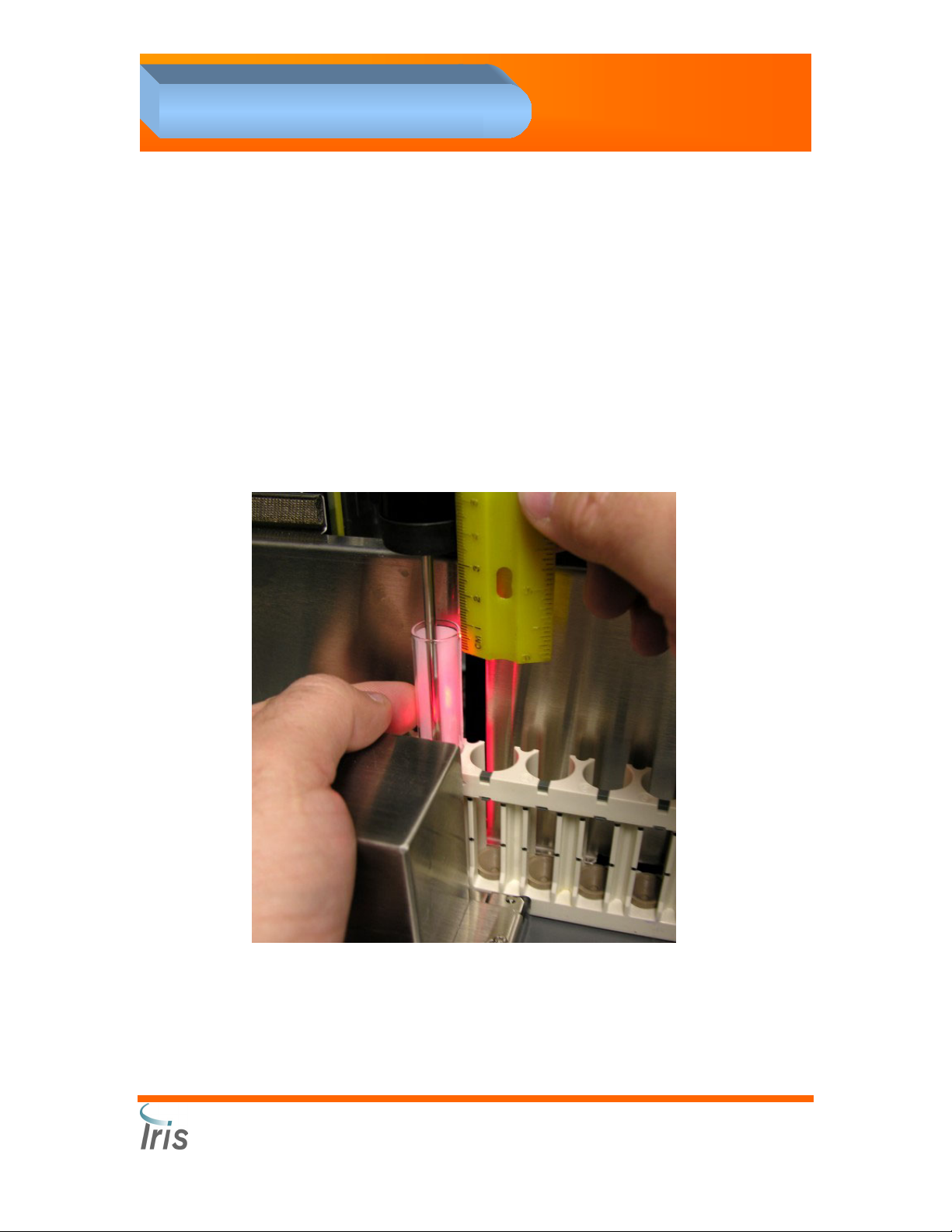
4. Adjustments
Test Tube depth positioning
SPA pipette depth calibration check:
1. On the Service Application’s SPA “HVL Sequences” branch, click on
“P0” pipette home and rotate to the tube
2. Then click on “P0” pipette home and rotate to the tube
3. Then click on “P1” pipette down to tube – during this sequence you
should check that the pipette descended down with only 3mm
clearance with a tolerance of +/- 0.5mm.
4. Then click on “P2” pipette up and rotate and down to waste well and
finally up from waste well.
Iris Diagnostics, a Division of International Remote Imaging Systems, Inc.
®
iQ
200 Sprint™ Automated Urine Microscopy Analyzer Service Manual 300-4949 Rev A 01/2005 4-13
Page 91

4. Adjustments
SPA pipette depth adjustment:
1. This procedure should only be done if it is determined that the test
tube depth positioning is incorrect. From the top windows tool bar
click Jog.
2. Select SPA Vertical Jog (The Velocity window will appear).
3. From the Jog Velocity window, select Home.
4. Using the up down arrows on the keyboard, lower the pipette into the
test tube until it’s 3mm from the bottom of the tube (the test tube can
be lifted to determine the distance the pipette is from the bottom of
the tube) then click Home then “OK”.
5. From the Service Applications menu tree SPA Calibration table
Double click on cal[3]:Double click here to auto set .
6. Click YES to confirm. The new calibration value has now been set.
7. From the SPA sequence menu, double-click PH-Pipettor Home.
8. Perform the “SPA pipette depth calibration check” procedure. If the
system hangs during this procedure, you will need to call Iris
Technical Service for cal [31] to determine this new calibration value.
9. Exit Service Mode.
Iris Diagnostics, a Division of International Remote Imaging Systems, Inc.
®
iQ
200 Sprint™ Automated Urine Microscopy Analyzer Service Manual 300-4949 Rev A 01/2005 4-14
Page 92

4. Adjustments
Waste Well Depth Positioning
Cal 31 value is pre-set in factory. If any adjustment is needed,
contact Iris Technical Services.
Lamina Consumption Adjustment
Cal 30 value is pre-set in factory. If any adjustment is needed,
contact Iris Technical Services.
Iris Diagnostics, a Division of International Remote Imaging Systems, Inc.
®
iQ
200 Sprint™ Automated Urine Microscopy Analyzer Service Manual 300-4949 Rev A 01/2005 4-15
Page 93

4. Adjustments
Air Pressure Calibration
Material required
Calibrated air pressure gauge
16 x 100 mm round bottom glass tubes
Iris Diluent
Procedure
1. Remove the shield to access the front of the instrument.
2. Insert a T fitting between the air pressure pump line and the air
pressure bottle (black connector).
3. Run a line from the T fitting to a calibrated air pressure gauge.
4. Place a tube with 10mL of Diluent in a rack.
5. Place the rack on the right side of the sampler and press GO. The air
system pressurizes during the fluid wash procedure.
6. Read the air pressure on the air pressure gauge following the sample
cycle. The air pressure should be between 5.0 ±0.5psi.
7. If the air pressure needs to be adjusted, proceed with the following
steps:
a. Start the Service Application.
b. Under the SPA Calibration, adjust the value cal [14]: pressure
setting. If the air pressure is too high, decrease the pressure
setting value by one step at the time (2 Hex = 1 psi.)
c. Repeat steps 4 through 6 until the air pressure reading on the
gauge is within the acceptable range.
8. Process several samples after the adjustment has been made:
a. When the pipette descends into a sample tube, the pipette
releases a single large bolus of air. The sample will shoot up
inside the tube to about 1 cm from the top of the tube.
b. If the sample overflows the top of the tube, decrease the air
pressure.
9. Acceptance criteria:
a. Air pressure: 5.0 ±0.5psi.
Iris Diagnostics, a Division of International Remote Imaging Systems, Inc.
®
iQ
200 Sprint™ Automated Urine Microscopy Analyzer Service Manual 300-4949 Rev A 01/2005 4-16
Page 94

p
4. Adjustments
Barcode Reader Alignment
Material Required
Procedure
NOTE: The light beam from the Barcode Reader is of low intensity and
usually difficult to see. Reducing the ambient light will increase the
visibility of the beam.
Routine Rack
16 x 100 mm glass test tube
Barcode reader alignment tool PN 725-3090
Barcode reader Y cable PN 250-3084
Barcode Reader Field Software PN 700-3110
Make sure the Sampler Calibration has been performed.
Prepare Barcode Reader Connections
1. Turn the iQ200 microscopy unit off.
2. Remove the Lower Front Panel assembly.
3. Use the Barcode Reader “Y” cable (IRIS part# 250-3084) for RS232
and 5 VDC power connection to the Barcode Reader.
Connect to
barcode reader
Connect to RS232
laptop
communication port
Connect to J13 on
back plane for
5volts
ower
Iris Diagnostics, a Division of International Remote Imaging Systems, Inc.
®
iQ
200 Sprint™ Automated Urine Microscopy Analyzer Service Manual 300-4949 Rev A 01/2005 4-17
Page 95
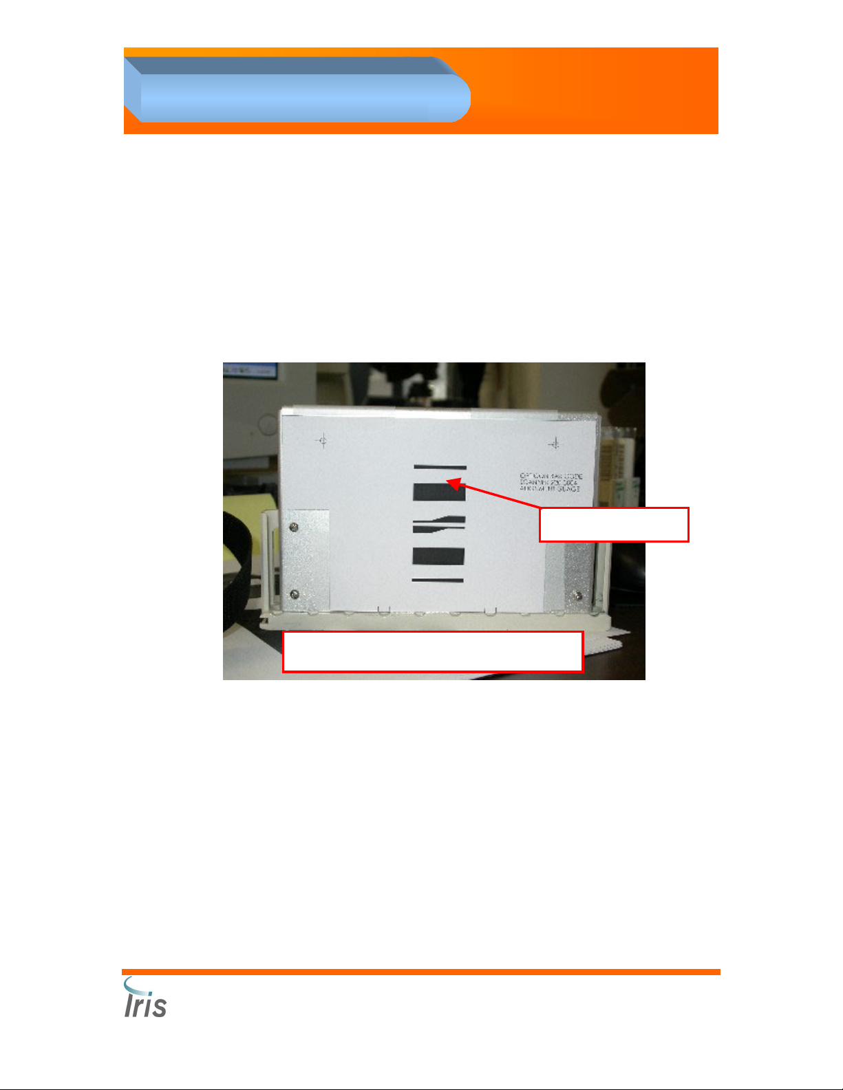
4. Adjustments
4. Connect the permanent cable from the Barcode reader to the female
receptacle on the “Y” cable for the alignment.
5. Connect the J13 connector on the “Y” cable to J13 on the Backplane.
Do not force the J13 connector, it is keyed to go in one way.
6. Turn on the iQ200 to power up the barcode scanner.
7. Connect the RS 232 cable to the communication port of the laptop.
Load the Alignment Tool
1. Load the “Barcode Reader Alignment Tool” (IRIS part# 725-3090) like
a normal rack in the iQ200 sampler.
Alignment Graphic
Barcode Reader Alignment Tool
2. Start the Service Application.
3. From the Service Application, click on STM, then Sequences.
4. Double-click on Initialize Rack M1 and then click OK.
5. Double-click on Move Next MN and then click OK until the rack is
positioned at the fifth position.
6. Leave the Alignment tool in the fifth (5
th
) position.
Perform barcode alignment
1. Start the “Barcode Utility Program” from the Laptop computer.
2. Use the COM Setup drop down menu on the main screen to select an
open COM port (probably COM1 on a laptop) in order to establish
communication between the Barcode reader and the laptop. The
main screen view should display “Online” if the connection is
successful.
Iris Diagnostics, a Division of International Remote Imaging Systems, Inc.
®
iQ
200 Sprint™ Automated Urine Microscopy Analyzer Service Manual 300-4949 Rev A 01/2005 4-18
Page 96

4. Adjustments
3. Click the “Align” button to perform the
Barcode Scanner alignment. The screen on
the right will be displayed.
4. The screen will probably be like one of the
next two views:
• Red is way out of alignment
• Green is close to being aligned
If the indicator is
The barcode reader
positioned
HIGH Needs to be aimed lower
LOW Needs to be aimed higher
LEFT Needs to move to the right
RIGHT Needs to move to the left
CLOSE Is to close
FAR Is to far
Iris Diagnostics, a Division of International Remote Imaging Systems, Inc.
®
iQ
200 Sprint™ Automated Urine Microscopy Analyzer Service Manual 300-4949 Rev A 01/2005 4-19
Page 97

4. Adjustments
Tilt pivot, “up and
down
Tilt locking screw
Focus, “close and
Lateral adjustment slots, “left
and right”
far” slots
5. Move the reader until the green circle is perfectly centered on the
cross hairs, and the distance bar is centered and green. Tighten all
the screws to hold the readers position when it is aligned.
6. Install the Lower Front Panel assembly. Ensure that the “Barcode
Utility Program” Alignment screen is still the same. There should be
no change in the alignment on the screen.
7. Click the Exit button when the alignment is completed and the reader
is aligned.
8. Close the “Barcode Utility Program”.
9. Ensure that all of the alignment and mounting screws are tight.
10. Turn off the iQ200 power.
11. Remove the “Y” Cable.
12. Plug the cable from the reader into J13 on the Backplane. Do not
force the J13 connector it is keyed to go in one way (key is facing
down for proper orientation).
13. Exit the Service Application.
14. Restart the entire iQ200 system.
Iris Diagnostics, a Division of International Remote Imaging Systems, Inc.
®
iQ
200 Sprint™ Automated Urine Microscopy Analyzer Service Manual 300-4949 Rev A 01/2005 4-20
Page 98

4. Adjustments
Validation
1. To ensure the barcode reader is reading and the system is working,
load an iQ200 control rack with properly labeled tubes to perform
Prime (first three tubes), Focus (5
th
(6
and 7th tube). Check the results to be sure that the system is
working properly.
2. Load a rack with tubes labeled with the customers labels filled with
any material (focus, positive control, diluent, tap water etc.) Run the
rack on the iQ200 system and check the results in the Work list to be
sure that all labels read properly. If connected to an AX-4280, run the
sample rack on both analyzers, and make sure that chemistry and
microscopy results are attached.
3. If the system performs properly, the procedure is complete
4. If the barcodes do not read properly, recheck the alignment (it will be
necessary to reinstall the “y” cable and hook up the laptop again to do
so).
th
tube) and Positive / Negative QC
Iris Diagnostics, a Division of International Remote Imaging Systems, Inc.
®
iQ
200 Sprint™ Automated Urine Microscopy Analyzer Service Manual 300-4949 Rev A 01/2005 4-21
Page 99

4. Adjustments
Collimation
What is a Collimation?
Collimation is the adjustment of the alignment of each optical element
with regard to the others. The collimation is a way of improving
considerably the optical performance. No high-resolution result can be
obtained without an near perfect collimation, since image processing is
incapable of compensating for the damages caused by a misalignment.
Condenser Alignment
1. Open the Service application.
2. From the Service application, click on View then Video to display the
live video.
3. In Video View, the Avg light should be about 210 and the Var. should
be lower than .035.
Iris Diagnostics, a Division of International Remote Imaging Systems, Inc.
®
iQ
200 Sprint™ Automated Urine Microscopy Analyzer Service Manual 300-4949 Rev A 01/2005 4-22
Page 100

4. Adjustments
4. Turn the vertical knob clockwise to reach one edge of iris.
5. Turn the vertical adjustment knob counter clockwise to the other edge
of the iris.
6. Adjust the vertical knob until the condenser is centered.
7. Repeat above steps with the horizontal knob until the image is
centered.
8. Close the Live Video window.
9. Exit the Service Application.
Run Auto Focus
Run one glass tube with barcode label filled with 6mL of Focus in position
5 of a QC rack.
Vertical
adjustment
Horizontal
adjustment
Iris Diagnostics, a Division of International Remote Imaging Systems, Inc.
®
iQ
200 Sprint™ Automated Urine Microscopy Analyzer Service Manual 300-4949 Rev A 01/2005 4-23
 Loading...