

Page 1
AUTOMLAB
V
w
t
i
dc motor
V
t
i
w
1/L
1/s
V
Kphi
Kphi
R
w
b
t
i
© 2012 IRAI
1 AUTOMLAB
Page 2

Page 3

Sommaire
AUTOMLAB ................................................................................................................ 1
Concept ................................................................................................................... 5
Necessary softwares ............................................................................................... 5
Building diagrams ................................................................................................... 5
Functional principle ................................................................................................. 5
Values display ......................................................................................................... 6
Solving time ............................................................................................................ 6
Timescale ................................................................................................................ 6
Blocks list ................................................................................................................ 7
Source/Source ..................................................................................................... 7
Source/Boolean ................................................................................................... 7
Source/Steps ....................................................................................................... 8
Source/Slope ....................................................................................................... 8
Source/Step ......................................................................................................... 9
Source/ Repetitive sequence ............................................................................... 9
Source/Sinus ..................................................................................................... 10
Target/Target ..................................................................................................... 10
Target/Boolean .................................................................................................. 11
Continuous/Integrator ........................................................................................ 11
Continuous/Limited integrator ............................................................................ 12
Continuous/Derivator ................................................................ ......................... 12
Continuous/PID ................................................................................................. 12
Discontinuous/Saturation ................................................................................... 13
Instrumentation/Display ................................ ..................................................... 14
Other/Lookup table ............................................................................................ 14
Logic ................................ ................................ ................................ .................. 14
Logic/Comparison.............................................................................................. 15
Math .................................................................................................................. 15
Math/Gain .......................................................................................................... 15
User ................................................................ ................................................... 16
Encapsulation of blocks ........................................................................................ 19
Customizing the palette ......................................................................................... 20
3 AUTOMLAB
Page 4

Add a block to the library ....................................................................................... 20
Managing folders corresponding to an encapsulation ........................................... 20
Display a bitmap on a block .................................................................................. 20
4 AUTOMLAB
Page 5

Concept
AUTOMLAB is an AUTOMGEN module allowing physical systems simulation. The
description of the systems is achieved through the use of function blocks.
AUTOMLAB est un module d’AUTOMGEN permettant la simulation de systèmes
physiques. La description des systèmes est réalisée par l’utilisation de blocs type
« Simulink ». AUTOMLAB can interact with the other IRAI softwares : AUTOMGEN,
VIRTUAL UNIVERSE, AUTOMSIM. AUTOMLAB was developed on an original idea
by Philippe Perro.
Necessary softwares
AUTOMLAB needs AUTOMGEN V>=8.019 and VIRTUAL UNIVERSE V>=1.018.
Building diagrams
The creation of diagrams is performed on AUTOMISM folders. The diagrams may
coexist with the other application items: program folders, SysML, Scada, 3D
simulation, etc. Some AUTOMLAB blocks may be found on the AUTOMLAB palette,
whole blocks can be found in the assistant: right click on the AUTOMSIM folder, and
select "Assistant/Add an object" then "Automlab".
Functional principle
Each block can have one or more entries on the left side of the block and one or
more outputs on the right side. Blocks can also contain parameters. To reference a
parameter in an area "content", use the syntax {parameter name}. The encapsulation
of the blocks is possible (see "encapsulation").
5 AUTOMLAB
Page 6

Values display
It is possible to add test points using the integrated display of curves AUTOMSIM:
Right-click a connection diagram, then "Add a measuring point here." Move the
cursor over a connection to display the value at that point. The AUTOMLAB "Display"
object can also display a value.
Solving time
The solving time is the executor AUTOMGEN PC execution period. This time is set in
the item "Configuration / post-processor / PC / Run / Period" in milliseconds. The
resolution time is the complete resolution of all diagrams.
Timescale
This parameter sets the time scale for the simulation.
A value of zero or 1 indicates a real-time resolution.
A value of n greater than 1 indicates that the time passes n times faster than real
time. For example, 10 to 10 times faster.
n value between 0 and 1 indicates that the flow time of 1 / n times slower. For
example, 0.1 to 10 times slower.
6 AUTOMLAB
Page 7

Blocks list
in
BOOL
Source/Source
Sets a source.
The area "content" can receive a
constant, a variable name or a symbol.
The types of variables used are 16-bit
words, 32-bits words and floating. For
boolean variables, use the block
"Source / Boolean".
Examples:
1.5
%mf1000
%mw400
%md200
Source/Boolean
Sets a Boolean source.
Example:
%i0
%q0
%m100
7 AUTOMLAB
Page 8

Source/Steps
PULSE
RAMP
Sets a source generating pulse, the
parameters are:
- amplitude: amplitude known signal,
- period0: how long the signal takes
the value 0,
- period1: how long the signal takes
the value "amplitude."
Source/Slope
Set a source generating a ramp, the
parameters are:
- initial value: the initial value,
- slop: the slope.
8 AUTOMLAB
Page 9
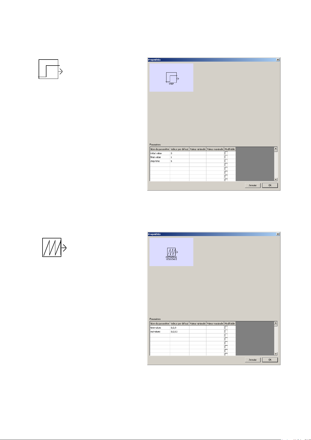
Source/Step
STEP
REPEATING
SEQUENCE
Sets a source with a change in value
that occurs at a defined time. The
time is calculated from the beginning
of the simulation. The parameters
are:
- initial value: the value that will exit
before time runs out,
- final value: the value that will exit
after the time is up,
- step time: time in seconds,
decimal values can be used.
Source/ Repetitive sequence
Sets a source generating a repetitive
sequence.
The parameters are:
- Time values in seconds,
- The output values at each time.
Intermediate values are extrapolated.
9 AUTOMLAB
Page 10

Source/Sinus
SINE WAVE
out
Sets a sinusoidal source. The
parameters are:
- Amplitute,
- Frequency,
- Bias,
- Phase.
The following formula gives the
sleep of the output:
Output=ampiltude * sinus (frequency * time + phase) + bias
Target/Target
Set a target.
The area "content" can receive a
variable name or a symbol. The
types of variables used are 16-bit
words, 32-bits words and floating.
For boolean variables, use the block
"Target / Boolean."Examples :
%mf1000
%mw400
%md200
10 AUTOMLAB
Page 11

Target/Boolean
BOOL
1/s
Set a boolean target.
Example :
%q0
%m100
Continuous/Integrator
Integrates the signal.
11 AUTOMLAB
Page 12

Continuous/Limited integrator
1/s
INTEGRATOR
LIMITED
du/dt
PID
Integrates the signal, the parameters
are:
- Min: minimum value output,
- Max: maximum output,
- Init: initial value of the output.
Continuous/Derivator
Dérivate the signal.
Continuous/PID
PID block, the parameters are:
- P proportional coefficient,
- I integral coefficient,
- D derivate coefficient,
- N filter coefficient.
12 AUTOMLAB
Page 13

The model corresponding to the PID block is as follows:
P
ID1/s
N
1/s
SATURATION
Discontinuous/Saturation
Limits the amplitude of the signal.
The parameters are:
- Min: minimum value,
- Max:. Maximum value.
13 AUTOMLAB
Page 14

Instrumentation/Display
0.00
LOOKUP
NOT
ANDORXOR
Displays the value of the signal.
Other/Lookup table
Generates an output signal by
converting the input signal from a
table. The values are interpolated. The
parameters are:
- InValue: the input values separated
by commas,
- Outvalues: the output values
separated by commas.
Logic
Boolean operations. The logic states are defined as follows:
Signal = 0: false
Signal <> 0: true
14 AUTOMLAB
Page 15

Logic/Comparison
~===<><=
>=
ADD
SUB
MUL
DIV
1
Compares the two signals. The Boolean result is 0 for false and 1 for true.
Math
Performs a calculation between two input signals.
Math/Gain
Multiplies the input by the gain
specified in the "Content".
15 AUTOMLAB
Page 16

User
user
This block allows you to create a personalized treatment. You can choose the
number of inputs and outputs of the block and the number of internal variables.
Internal variables of the block are preserved between periodic execution of the
content block. The content must be written in literal language. Keywords allow access
to the block elements:
INPUTn reference output with n number of entries <n> 0 -1
Reference
OUTPUTn the exit with 0 <n <number of outputs -1
I
NTENALn intentional reference variable n with 0 <n <number of internal variables
ETIME: time between two execution of the block in seconds
TIME: time since the launch of the execution in seconds
All these variables are of type 32 bit float.
The syntax {Parameter} reference a parameter.
Example of a "Gain" block coding.
We set the parameter {gain} in the parameter list.
OUTPUT0:=INPUT0*{gain};
16 AUTOMLAB
Page 17

When a user block has been programmed, the elements content, text, display,
settings are automatically hidden when opening properties. Press the SHIFT key
while opening the property dialog box to show the hidden elements.
The "Additional display on the block" zone allows you to make simple drawings on
the surface of the block. The coordinates used are between 0 and 1. 1 corresponding
to the width or height. The following commands are available:
M x,y : move the pen
L x,y : draw a line
T x,y,"text" draw a text
Example:
M 0,0
L 1,1
Draw a line between 2 opposite corners of a block.
The majority of predefined blocks of AUTOMLAB are built with the "user" block,
observing the properties of these objects (leaving the SHIFT key pressed) illustrates
this.
17 AUTOMLAB
Page 18

Example for SATURATION block:
18 AUTOMLAB
Page 19
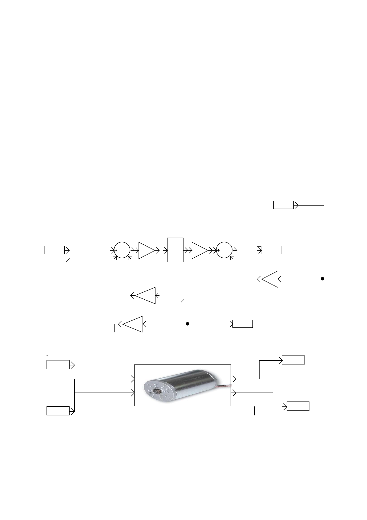
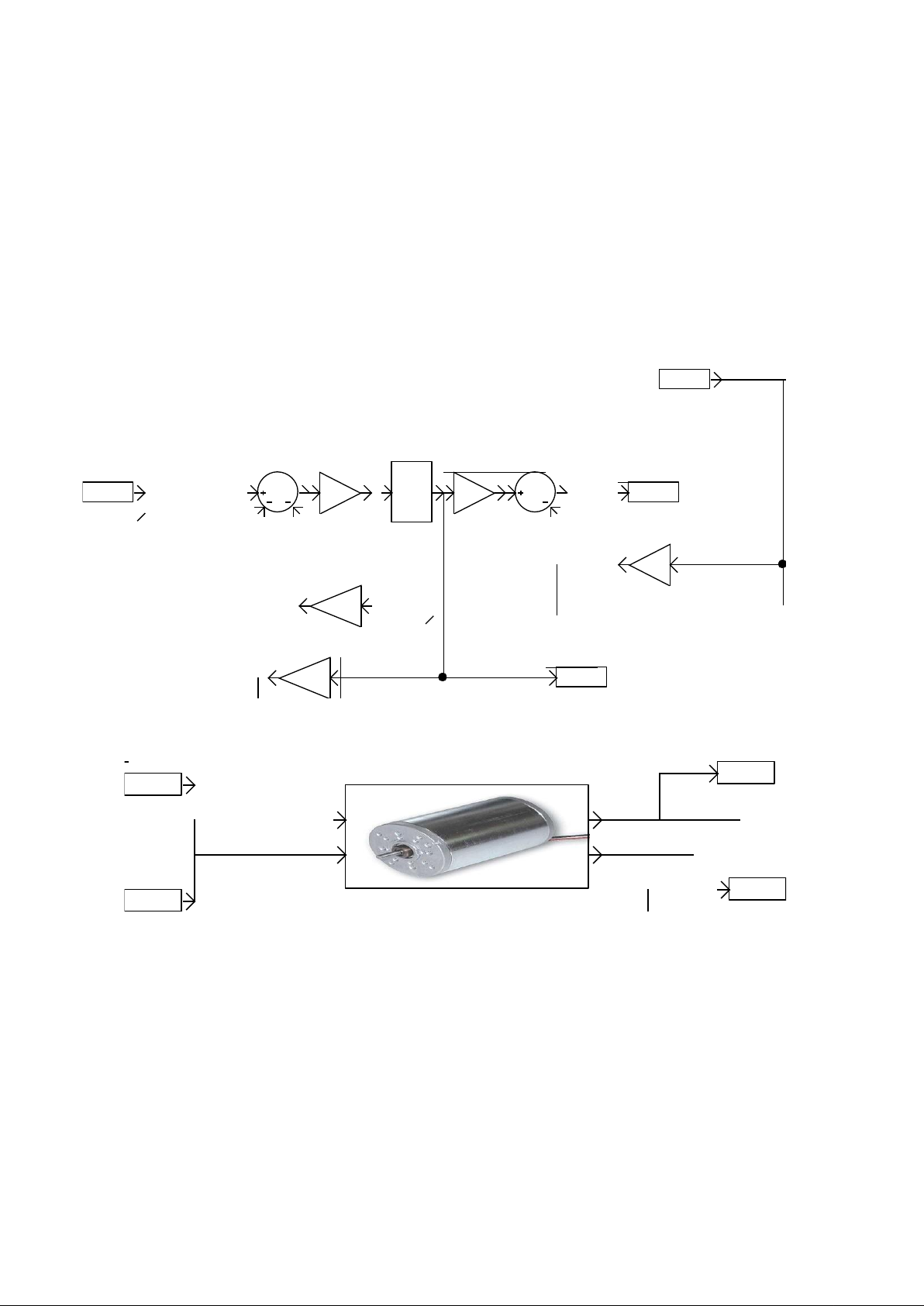
Encapsulation of blocks
1/L
1/s
V
Kphi
Kphi
R
w
b
t
i
V
w
t
i
dc motor
V
t
i
w
The principle of encapsulation of the blocks is as follows, the encapsulated diagram
is written on a AUTOMSIM folder whose name starts with the character '_'
(underscore). To change the name of a AUTOMSIM folder, click once with the left
mouse button on the name of the folder, wait a second and change the name.
This diagram may contain blocks whose source and target zone "Content" property
remains empty. These are the inputs and outputs of the block. The parameters used
in the encapsuled diagrams become block parameters if the "Editable" associated
with each parameter is checked.
The encapsulation of the block is performed using a block "Encapsulation", the
content area must be documented with the name of the folder in which the
encapsulated diagram is written (without the character '_' at begining).
Encapsulation sample:
19 AUTOMLAB
Page 20

Customizing the palette
To add a palette, select a portion of a diagram, click the right mouse button, select
"Export" and save the file in the "pal" subdirectory of the AUTOMGEN installation
directory. Restart AUTOMGEN to make the element appears. The file name is the
name of the palette displayed in AUTOMGEN.
Add a block to the library
To add a block diagram to the library (available in the wizard "Add Object"), select a
block or portion of a diagram, click the right mouse button, choose "Export" and save
the block in the subdirectory "AUTOMSIM \ lib" of the AUTOMGEN installation
directory. The subdirectory names correspond to the names of the categories.
Managing folders corresponding to an encapsulation
If a block is used as an encapsulating model in a palette or assistant, the folder
containing the encapsulation must be exported to the "AUTOMSIM \ syslib \ sub"
subdirectory. To do this, select all the elements of the encapsulated folder, and then
export them (right-click "Export") in the subdirectory name as giving the name of the
subfield specified in the properties of the encapsulating block. The PID block is an
example of using this.
Display a bitmap on a block
To display a bitmap on a block, attach an AUTOMSIM drawing object / bitmap block
and group the two objects (select the two objects, then right click and "Group").
20 AUTOMLAB
 Loading...